


MILLPWR Setup Access Code
An access code must be entered before the installation setup parameters can be accessed or changed.
IMPORTANT
The access code is 8891.
Refer to Section 7, Setup.
IMPORTANT
Supervisors may wish to remove this page from the MILLPWR Operation Manual after initially setting up the installation setup parameters. Keep it in a safe place for future use.

|
TABLE OF CONTENTS |
|||
MILLPWR® |
|
|
|
|
|
|
|
|
|
Introduction |
1-1 |
|
|
|
|
|
|
||
System Overview . . . . . . . . . . . . . . . . . . . . . . . . . . . . . |
. . . . . . . . . . . . . .1-1 |
|
|
|
Operator Console Overview . . . . . . . . . . . . . . . . . . |
. . . . . . . . . . . . . .1-2 |
|
|
|
Keypad Layout . . . . . . . . . . . . . . . . . . . . . . . . . . . |
. . . . . . . . . . . . . .1-3 |
|
|
|
Screen Layout . . . . . . . . . . . . . . . . . . . . . . . . . . . . |
. . . . . . . . . . . . . .1-4 |
|
|
|
Table Stop Button . . . . . . . . . . . . . . . . . . . . . . . . . |
. . . . . . . . . . . . . .1-5 |
|
|
|
Conventions . . . . . . . . . . . . . . . . . . . . . . . . . . . . . . . . |
. . . . . . . . . . . . . .1-5 |
|
|
|
Axis Conventions . . . . . . . . . . . . . . . . . . . . . . . . . . |
. . . . . . . . . . . . . .1-5 |
|
|
|
Count Direction . . . . . . . . . . . . . . . . . . . . . . . . |
. . . . . . . . . . . . . .1-5 |
|
|
|
Cartesian Coordinates . . . . . . . . . . . . . . . . . . . . . . . |
. . . . . . . . . . . . . .1-6 |
|
|
|
Polar Coordinates . . . . . . . . . . . . . . . . . . . . . . . . . . |
. . . . . . . . . . . . . .1-6 |
|
|
|
Absolute and Incremental Dimensions . . . . . . . . . . |
. . . . . . . . . . . . . .1-7 |
|
|
|
Saving, Backing Up, and Creating Directories . . . . |
. . . . . . . . . . . . . .1-8 |
|
|
|
DRO . . . . . . . . . . . . . . . . . . . . . . . . . . . . . . . . . . . . . . . . . . . |
. . . . . . . . . . . . . .2-1 |
|
|
|
Start Up . . . . . . . . . . . . . . . . . . . . . . . . . . . . . . . . . . . . |
. . . . . . . . . . . . . .2-1 |
|
|
|
Power Up . . . . . . . . . . . . . . . . . . . . . . . . . . . . . . . . |
. . . . . . . . . . . . . .2-1 |
|
|
|
Screen Saver . . . . . . . . . . . . . . . . . . . . . . . . . . . . . . |
. . . . . . . . . . . . . .2-1 |
|
|
|
Finding Home . . . . . . . . . . . . . . . . . . . . . . . . . . . . |
. . . . . . . . . . . . . .2-2 |
|
|
|
DRO Functions . . . . . . . . . . . . . . . . . . . . . . . . . . . . . . |
. . . . . . . . . . . . . .2-3 |
|
|
|
Move Table . . . . . . . . . . . . . . . . . . . . . . . . . . . . . . |
. . . . . . . . . . . . . .2-3 |
|
|
|
Teach Position . . . . . . . . . . . . . . . . . . . . . . . . . . . . |
. . . . . . . . . . . . . .2-4 |
|
|
|
Using an Electronic Edge Finder . . . . . . . . . . . . . . |
. . . . . . . . . . . . . .2-5 |
|
|
|
Skewing a Part . . . . . . . . . . . . . . . . . . . . . . . . . . . . |
. . . . . . . . . . . . . .2-6 |
|
|
|
Establishing Datum . . . . . . . . . . . . . . . . . . . . . . . . |
. . . . . . . . . . . . . .2-8 |
|
|
|
Hard Key Milling Functions . . . . . . . . . . . . . . . . . |
. . . . . . . . . . . . . .2-11 |
|
|
|
Programming . . . . . . . . . . . . . . . . . . . . . . . . . . . . . . . . . . . |
. . . . . . . . . . . . . .3-1 |
|
|
|
Programming Considerations . . . . . . . . . . . . . . . . . . . . |
. . . . . . . . . . . . . .3-1 |
|
|
|
"From" and "To" Points . . . . . . . . . . . . . . . . . . . . . |
. . . . . . . . . . . . . .3-1 |
|
|
|
Depth of Cut . . . . . . . . . . . . . . . . . . . . . . . . . . . . . |
. . . . . . . . . . . . . .3-1 |
|
|
|
Tool Offset . . . . . . . . . . . . . . . . . . . . . . . . . . . . . . . |
. . . . . . . . . . . . . .3-1 |
|
|
|
Datum Selection . . . . . . . . . . . . . . . . . . . . . . . . . . |
. . . . . . . . . . . . . .3-2 |
|
|
|
Absolute and Incremental Dimensions . . . . . . . . . . |
. . . . . . . . . . . . . .3-2 |
|
|
|
Continuous Milling . . . . . . . . . . . . . . . . . . . . . . . . |
. . . . . . . . . . . . . .3-3 |
|
|
|
Creating a Program . . . . . . . . . . . . . . . . . . . . . . . . . . . |
. . . . . . . . . . . . . .3-4 |
|
|
|
The View Key . . . . . . . . . . . . . . . . . . . . . . . . . . . . |
. . . . . . . . . . . . . .3-6 |
|
|
|
Follow Tool . . . . . . . . . . . . . . . . . . . . . . . . . . . . |
. . . . . . . . . . . . . .3-6 |
|
|
|
Show Tool Path . . . . . . . . . . . . . . . . . . . . . . . . . |
. . . . . . . . . . . . . .3-6 |
|
|
|
Zoom In, Zoom Out and Restore . . . . . . . . . . . . |
. . . . . . . . . . . . . .3-6 |
|
|
|
Operation Manual |
i |

TABLE OF CONTENTS
MILLPWR®
Running a Program . . . . . . . . . . . . . . . . . . . . . . . . . . . . . . . . . . . . . . . . |
.3-7 |
Skewing a Part . . . . . . . . . . . . . . . . . . . . . . . . . . . . . . . . . . . . . . . . . . |
3-7 |
Establishing Datum . . . . . . . . . . . . . . . . . . . . . . . . . . . . . . . . . . . . . . |
3-9 |
Testing Your Program . . . . . . . . . . . . . . . . . . . . . . . . . . . . . . . . . . . . |
3-12 |
Single Step . . . . . . . . . . . . . . . . . . . . . . . . . . . . . . . . . . . . . . . . . . |
3-12 |
Dry Run . . . . . . . . . . . . . . . . . . . . . . . . . . . . . . . . . . . . . . . . . . . . |
3-12 |
Graphics Only . . . . . . . . . . . . . . . . . . . . . . . . . . . . . . . . . . . . . . . . |
3-12 |
Manual Positioning . . . . . . . . . . . . . . . . . . . . . . . . . . . . . . . . . . . . |
3-13 |
Disable Look Ahead . . . . . . . . . . . . . . . . . . . . . . . . . . . . . . . . . . . |
3-13 |
Pressing the GO Key . . . . . . . . . . . . . . . . . . . . . . . . . . . . . . . . . . . . . |
3-14 |
Feed + and Feed - . . . . . . . . . . . . . . . . . . . . . . . . . . . . . . . . . . . . . . . |
3-15 |
Machining to Zero . . . . . . . . . . . . . . . . . . . . . . . . . . . . . . . . . . . . . . . |
3-16 |
Program Functions . . . . . . . . . . . . . . . . . . . . . . . . . . . . . . . . . . . . . . . . . . |
3-17 |
Accessing the Load, Save, Delete, Merge Backup and |
|
Directory Options . . . . . . . . . . . . . . . . . . . . . . . . . . . . . . . . . . . . . |
3-17 |
Directories . . . . . . . . . . . . . . . . . . . . . . . . . . . . . . . . . . . . . . . . . . . . . |
3-18 |
Creating a Subdirectory . . . . . . . . . . . . . . . . . . . . . . . . . . . . . . . . |
3-19 |
Selecting a Directory . . . . . . . . . . . . . . . . . . . . . . . . . . . . . . . . . . |
3-21 |
Deleting a Directory . . . . . . . . . . . . . . . . . . . . . . . . . . . . . . . . . . . |
3-23 |
Saving a Program . . . . . . . . . . . . . . . . . . . . . . . . . . . . . . . . . . . . . . . . |
3-24 |
Naming a Program . . . . . . . . . . . . . . . . . . . . . . . . . . . . . . . . . . . . . . . |
3-25 |
Loading a MILLPWR (MPT) Program . . . . . . . . . . . . . . . . . . . . . . . . |
3-26 |
From MILLPWR's internal memory . . . . . . . . . . . . . . . . . . . . . . . . . |
3-26 |
From a 31/2" floppy disk . . . . . . . . . . . . . . . . . . . . . . . . . . . . . . . . |
3-27 |
From your PC . . . . . . . . . . . . . . . . . . . . . . . . . . . . . . . . . . . . . . . |
3-28 |
Translating a DXF file . . . . . . . . . . . . . . . . . . . . . . . . . . . . . . . . . . . . |
3-28 |
Loading a G-code file . . . . . . . . . . . . . . . . . . . . . . . . . . . . . . . . . . . . . |
3-29 |
Running a G-code Program . . . . . . . . . . . . . . . . . . . . . . . . . . . . . . . . . |
3-31 |
MILLPWR G-code Conventions . . . . . . . . . . . . . . . . . . . . . . . . . . . . . . . . . |
3-33 |
Merging Programs . . . . . . . . . . . . . . . . . . . . . . . . . . . . . . . . . . . . . . . |
3-37 |
Backing Up a Program . . . . . . . . . . . . . . . . . . . . . . . . . . . . . . . . . . . . |
3-38 |
Deleting a Program . . . . . . . . . . . . . . . . . . . . . . . . . . . . . . . . . . . . . . |
3-39 |
Demonstration Program . . . . . . . . . . . . . . . . . . . . . . . . . . . . . . . . . . . . . . |
.4-1 |
Selecting Datum . . . . . . . . . . . . . . . . . . . . . . . . . . . . . . . . . . . . . . . . . . . |
4-1 |
Beginning the Program . . . . . . . . . . . . . . . . . . . . . . . . . . . . . . . . . . . . . . |
4-2 |
Selecting a Tool . . . . . . . . . . . . . . . . . . . . . . . . . . . . . . . . . . . . . . . . . |
4-2 |
Programming the Contour . . . . . . . . . . . . . . . . . . . . . . . . . . . . . . . . . |
4-4 |
Programming the Bolthole Pattern . . . . . . . . . . . . . . . . . . . . . . . . . . . |
4-12 |
Programming the Rectangular Pocket . . . . . . . . . . . . . . . . . . . . . . . . . |
4-15 |
Saving Your Program . . . . . . . . . . . . . . . . . . . . . . . . . . . . . . . . . . . . . . . . |
4-17 |
Testing Your Program . . . . . . . . . . . . . . . . . . . . . . . . . . . . . . . . . . . . . . . |
4-18 |
|
|
ii |
Operation Manual |

TABLE OF CONTENTS
MILLPWR®
Running the Program . . . . . . . . . . . . . . . . . . . . . . . . . . . . . . . . . . . . . . . .4-19
Tool Changes . . . . . . . . . . . . . . . . . . . . . . . . . . . . . . . . . . . . . . . . . . . . . .4-20
Clearing the Program . . . . . . . . . . . . . . . . . . . . . . . . . . . . . . . . . . . . . . . .4-20
Program Steps . . . . |
. . . . . . . . . . . . . . . . . . . . . . . . . . . . . . . . . . . . . . . . . . . |
.5-1 |
Simple Milling and Drilling . . . . . . . . . . . . . . . . . . . . . . . . . . . . . . . . . . . |
5-1 |
|
Set Tool . . . |
. . . . . . . . . . . . . . . . . . . . . . . . . . . . . . . . . . . . . . . . . . . . |
5-1 |
Programming a Tool Step w/Repeatable Tool Length Offsets . . . . . . . . . . |
5-2 |
|
Entering the First Tool . . . . . . . . . . . . . . . . . . . . . . . . . . . . . . . . . . . . |
5-2 |
|
Changing to a Tool of Unknown Length in the DRO . . . . . . . . . . . . . . |
5-4 |
|
Changing to a Tool Of Unknown Length in PGM . . . . . . . . . . . . . . . . |
5-4 |
|
Position/Drill |
. . . . . . . . . . . . . . . . . . . . . . . . . . . . . . . . . . . . . . . . . . . |
5-6 |
Center Line . . . . . . . . . . . . . . . . . . . . . . . . . . . . . . . . . . . . . . . . . . |
5-6 |
|
Line . . . . . . . . . . . . . . . . . . . . . . . . . . . . . . . . . . . . . . . . . . . . . . .5-7 |
||
Arc . . . . |
. . . . . . . . . . . . . . . . . . . . . . . . . . . . . . . . . . . . . . . . . . . .5-8 |
|
Blend . . . |
. . . . . . . . . . . . . . . . . . . . . . . . . . . . . . . . . . . . . . . . . . .5-10 |
|
Rectangular Milling Functions . . . . . . . . . . . . . . . . . . . . . . . . . . . . . . . . . |
5-12 |
|
Pocket . . . . . |
. . . . . . . . . . . . . . . . . . . . . . . . . . . . . . . . . . . . . . . . . . . . |
5-12 |
Frame . . . . . |
. . . . . . . . . . . . . . . . . . . . . . . . . . . . . . . . . . . . . . . . . . . . |
5-15 |
Face . . . . . . |
. . . . . . . . . . . . . . . . . . . . . . . . . . . . . . . . . . . . . . . . . . . . |
5-17 |
Slot . . . . . . . |
. . . . . . . . . . . . . . . . . . . . . . . . . . . . . . . . . . . . . . . . . . . . |
5-19 |
Circular Milling Functions . . . . . . . . . . . . . . . . . . . . . . . . . . . . . . . . . . . . |
5-21 |
|
Pocket . . . . . |
. . . . . . . . . . . . . . . . . . . . . . . . . . . . . . . . . . . . . . . . . . . . |
5-21 |
Frame . . . . . |
. . . . . . . . . . . . . . . . . . . . . . . . . . . . . . . . . . . . . . . . . . . . |
5-23 |
Ring . . . . . . |
. . . . . . . . . . . . . . . . . . . . . . . . . . . . . . . . . . . . . . . . . . . . |
5-25 |
Hole Patterns . . |
. . . . . . . . . . . . . . . . . . . . . . . . . . . . . . . . . . . . . . . . . . . . |
5-27 |
Row of Holes |
. . . . . . . . . . . . . . . . . . . . . . . . . . . . . . . . . . . . . . . . . . . |
5-27 |
Hole Frame and Hole Array . . . . . . . . . . . . . . . . . . . . . . . . . . . . . . . . |
5-29 |
|
Bolthole Circle Patterns . . . . . . . . . . . . . . . . . . . . . . . . . . . . . . . . . . . |
5-31 |
|
Additional Milling Functions . . . . . . . . . . . . . . . . . . . . . . . . . . . . . . . . . . |
5-33 |
|
Custom Pocket . . . . . . . . . . . . . . . . . . . . . . . . . . . . . . . . . . . . . . . . . . |
5-33 |
|
Repeat . . . . |
. . . . . . . . . . . . . . . . . . . . . . . . . . . . . . . . . . . . . . . . . . . . |
5-35 |
Rotate . . . . . |
. . . . . . . . . . . . . . . . . . . . . . . . . . . . . . . . . . . . . . . . . . . . |
5-36 |
Mirror . . . . . |
. . . . . . . . . . . . . . . . . . . . . . . . . . . . . . . . . . . . . . . . . . . . |
5-37 |
Contour . . . . |
. . . . . . . . . . . . . . . . . . . . . . . . . . . . . . . . . . . . . . . . . . . . |
5-38 |
Engrave . . . |
. . . . . . . . . . . . . . . . . . . . . . . . . . . . . . . . . . . . . . . . . . . . |
5-40 |
Engrave Line . . . . . . . . . . . . . . . . . . . . . . . . . . . . . . . . . . . . . . . . . |
5-40 |
|
Engrave Arc . . . . . . . . . . . . . . . . . . . . . . . . . . . . . . . . . . . . . . . . . |
5-43 |
|
Ellipse Frame |
. . . . . . . . . . . . . . . . . . . . . . . . . . . . . . . . . . . . . . . . . . . |
5-45 |
Chamfer . . . |
. . . . . . . . . . . . . . . . . . . . . . . . . . . . . . . . . . . . . . . . . . . . |
5-47 |
Reference Point . . . . . . . . . . . . . . . . . . . . . . . . . . . . . . . . . . . . . . . . . . |
5-49 |
|
|
|
|
Operation Manual |
|
iii |

TABLE OF CONTENTS
MILLPWR®
Island . . . . . . . . . . . . . . . . . . . . . . . . . . . . . . . . . . . . . . . . . . . . . . . . .5-50
Spiral . . . . . . . . . . . . . . . . . . . . . . . . . . . . . . . . . . . . . . . . . . . . . . . . .5-52
Comment Step . . . . . . . . . . . . . . . . . . . . . . . . . . . . . . . . . . . . . . . . . .5-54
Auxiliary Function (AMI Option) . . . . . . . . . . . . . . . . . . . . . . . . . . . .5-55
Step Functions . . . . . . . . . . . . . . . . . . . . . . . . . . . . . . . . . . . . . . . . . . . . .5-57
Explode . . . . . . . . . . . . . . . . . . . . . . . . . . . . . . . . . . . . . . . . . . . . . . .5-57
Reverse Step . . . . . . . . . . . . . . . . . . . . . . . . . . . . . . . . . . . . . . . . . . . .5-59
Reverse Path . . . . . . . . . . . . . . . . . . . . . . . . . . . . . . . . . . . . . . . . . . . .5-59
Change Steps . . . . . . . . . . . . . . . . . . . . . . . . . . . . . . . . . . . . . . . . . . .5-60
Delete Steps . . . . . . . . . . . . . . . . . . . . . . . . . . . . . . . . . . . . . . . . . . . .5-61
Copy/Move Steps . . . . . . . . . . . . . . . . . . . . . . . . . . . . . . . . . . . . . . . .5-62
Calculator . . . . . . . . . . . . . . . . . . . . . . . . . . . . . . . . . . . . . . . . . . . . . . . . . . . |
.6-1 |
Math Functions (+, -, x, ÷) . . . . . . . . . . . . . . . . . . . . . . . . . . . . . . . . . . . . |
6-2 |
Trig Functions . . . . . . . . . . . . . . . . . . . . . . . . . . . . . . . . . . . . . . . . . . . . . |
6-2 |
Geometry Functions . . . . . . . . . . . . . . . . . . . . . . . . . . . . . . . . . . . . . . . . |
6-4 |
Working with the Geometry Calculator . . . . . . . . . . . . . . . . . . . . . . . |
6-4 |
Calculator Functions . . . . . . . . . . . . . . . . . . . . . . . . . . . . . . . . . . . . . . |
6-7 |
Saving Results Calculated in GeoCalc . . . . . . . . . . . . . . . . . . . . . . |
6-7 |
Loading GeoCalc Results . . . . . . . . . . . . . . . . . . . . . . . . . . . . . . . |
6-8 |
Loading Programs into GeoCalc . . . . . . . . . . . . . . . . . . . . . . . . . . |
6-9 |
Clearing GeoCalc . . . . . . . . . . . . . . . . . . . . . . . . . . . . . . . . . . . . . |
6-9 |
Example Problem . . . . . . . . . . . . . . . . . . . . . . . . . . . . . . . . . . . . . . . . |
6-10 |
Strategy . . . . . . . . . . . . . . . . . . . . . . . . . . . . . . . . . . . . . . . . . . . . |
6-10 |
Starting the Program . . . . . . . . . . . . . . . . . . . . . . . . . . . . . . . . . . |
6-11 |
Entering the Lines . . . . . . . . . . . . . . . . . . . . . . . . . . . . . . . . . |
6-11 |
Finding the Arc . . . . . . . . . . . . . . . . . . . . . . . . . . . . . . . . . . . |
6-14 |
Finding the Points of Tangency . . . . . . . . . . . . . . . . . . . . . . . . |
6-15 |
Returning Features . . . . . . . . . . . . . . . . . . . . . . . . . . . . . . . . . |
6-16 |
RPM Functions . . . . . . . . . . . . . . . . . . . . . . . . . . . . . . . . . . . . . . . . . . . . . |
6-18 |
Setup . . . . . . . . . . . . . . . . . . . . . . . . . . . . . . . . . . . . . . . . . . . . . . . . . . . . . . . . .7-1 Overview . . . . . . . . . . . . . . . . . . . . . . . . . . . . . . . . . . . . . . . . . . . . . . . . .7-1 Job Setup . . . . . . . . . . . . . . . . . . . . . . . . . . . . . . . . . . . . . . . . . . . . . . . . .7-2 Tool Library . . . . . . . . . . . . . . . . . . . . . . . . . . . . . . . . . . . . . . . . . . . .7-2 Using the Tool Library with Repeatable Tool Length Offsets . . . . . . . . . .7-4 Entering the First Tool . . . . . . . . . . . . . . . . . . . . . . . . . . . . . . . . . .7-5 Using the Tool Library . . . . . . . . . . . . . . . . . . . . . . . . . . . . . . . . .7-7 Scale Factor . . . . . . . . . . . . . . . . . . . . . . . . . . . . . . . . . . . . . . . . . . . .7-11 Display Options . . . . . . . . . . . . . . . . . . . . . . . . . . . . . . . . . . . . . . . . .7-12
iv |
Operation Manual |

TABLE OF CONTENTS
MILLPWR®
Angles . . . . . . . . . . . . . . . . . . . . . . . . . . . . . . . . . . . . . . . . . . . . . . . .7-12
INCR Display . . . . . . . . . . . . . . . . . . . . . . . . . . . . . . . . . . . . . . . .7-12
Display Resolution . . . . . . . . . . . . . . . . . . . . . . . . . . . . . . . . . . . .7-12
Point Entry . . . . . . . . . . . . . . . . . . . . . . . . . . . . . . . . . . . . . . . . . .7-12
From Point . . . . . . . . . . . . . . . . . . . . . . . . . . . . . . . . . . . . . . . . . .7-13
Stepover Entry . . . . . . . . . . . . . . . . . . . . . . . . . . . . . . . . . . . . . . .7-13
Electronic Edge Finder . . . . . . . . . . . . . . . . . . . . . . . . . . . . . . . . . . . .7-14
Job Clock . . . . . . . . . . . . . . . . . . . . . . . . . . . . . . . . . . . . . . . . . . . . . .7-14
Feed Rate Settings . . . . . . . . . . . . . . . . . . . . . . . . . . . . . . . . . . . . . . .7-16
Step Override % . . . . . . . . . . . . . . . . . . . . . . . . . . . . . . . . . . . . . .7-16
Max % . . . . . . . . . . . . . . . . . . . . . . . . . . . . . . . . . . . . . . . . . . . . .7-16
Min % . . . . . . . . . . . . . . . . . . . . . . . . . . . . . . . . . . . . . . . . . . . . . .7-16
Dry Run Speed . . . . . . . . . . . . . . . . . . . . . . . . . . . . . . . . . . . . . . .7-16
Default Feed Rate . . . . . . . . . . . . . . . . . . . . . . . . . . . . . . . . . . . . .7-16
Unit/(Min) . . . . . . . . . . . . . . . . . . . . . . . . . . . . . . . . . . . . . . . . . . .7-16
Full Cut Feed Rate % . . . . . . . . . . . . . . . . . . . . . . . . . . . . . . . . . .7-16
Installation Setup . . . . . . . . . . . . . . . . . . . . . . . . . . . . . . . . . . . . . . . . . . .7-17
Protection . . . . . . . . . . . . . . . . . . . . . . . . . . . . . . . . . . . . . . . . . . . . .7-17
Error Compensation . . . . . . . . . . . . . . . . . . . . . . . . . . . . . . . . . . . . . .7-18
Encoder Setup . . . . . . . . . . . . . . . . . . . . . . . . . . . . . . . . . . . . . . . . . . .7-19
Travel Limits . . . . . . . . . . . . . . . . . . . . . . . . . . . . . . . . . . . . . . . . . . .7-20
Error Checking . . . . . . . . . . . . . . . . . . . . . . . . . . . . . . . . . . . . . . . . . .7-21
Serial Port . . . . . . . . . . . . . . . . . . . . . . . . . . . . . . . . . . . . . . . . . . . . .7-22
Spindle Control . . . . . . . . . . . . . . . . . . . . . . . . . . . . . . . . . . . . . . . . . .7-23
Error Log . . . . . . . . . . . . . . . . . . . . . . . . . . . . . . . . . . . . . . . . . . . . . .7-23
Servo Tuning . . . . . . . . . . . . . . . . . . . . . . . . . . . . . . . . . . . . . . . . . . .7-24
Automatically Tuning the Servo in Console Mode . . . . . . . . . . . . .7-25
AMI Outputs . . . . . . . . . . . . . . . . . . . . . . . . . . . . . . . . . . . . . . . . . . . . . .7-27
Diagnostics . . . . . . . . . . . . . . . . . . . . . . . . . . . . . . . . . . . . . . . . . . . . . . . .7-28
Motor Assembly Monitor . . . . . . . . . . . . . . . . . . . . . . . . . . . . . . . . . .7-29
Signal Test . . . . . . . . . . . . . . . . . . . . . . . . . . . . . . . . . . . . . . . . . . . . .7-30
Table Stop Test . . . . . . . . . . . . . . . . . . . . . . . . . . . . . . . . . . . . . . . . . .7-31
Circle Interpolation Test . . . . . . . . . . . . . . . . . . . . . . . . . . . . . . . . . . .7-32
Examples of Test Results . . . . . . . . . . . . . . . . . . . . . . . . . . . . . . . .7-33
Keypad Test . . . . . . . . . . . . . . . . . . . . . . . . . . . . . . . . . . . . . . . . . . . .7-34
Display Test . . . . . . . . . . . . . . . . . . . . . . . . . . . . . . . . . . . . . . . . . . . .7-35
Disk Utilization . . . . . . . . . . . . . . . . . . . . . . . . . . . . . . . . . . . . . . . . . .7-36
Set Time and Date . . . . . . . . . . . . . . . . . . . . . . . . . . . . . . . . . . . . . . . .7-37
System Statistics . . . . . . . . . . . . . . . . . . . . . . . . . . . . . . . . . . . . . . . . .7-37
Max Servo Speed . . . . . . . . . . . . . . . . . . . . . . . . . . . . . . . . . . . . . . . . . . .7-38
Operation Manual |
v |

TABLE OF CONTENTS
MILLPWR®
Remote Storage . . . . . . . . . . . . . . . . . . . . . . . . . . . . . . . . . . . . . . . . . . . . . . .8-1 Equipment . . . . . . . . . . . . . . . . . . . . . . . . . . . . . . . . . . . . . . . . . . . . . . . .8-1 Choosing a Serial Cable . . . . . . . . . . . . . . . . . . . . . . . . . . . . . . . . . . . . . .8-1 Connecting MILLPWR to Your PC . . . . . . . . . . . . . . . . . . . . . . . . . . . . . . .8-2 Installing the Remote Storage Program onto a PC . . . . . . . . . . . . . . . . . . .8-3
For Windows® 95/98 . . . . . . . . . . . . . . . . . . . . . . . . . . . . . . . . . . . . . .8-3 For MS DOS® . . . . . . . . . . . . . . . . . . . . . . . . . . . . . . . . . . . . . . . . . .8-3 Setting Up a COM Port and BAUD Rates . . . . . . . . . . . . . . . . . . . . . . . . .8-4 Activating the Remote Storage Feature in MILLPWR . . . . . . . . . . . . . . . . .8-5 Troubleshooting . . . . . . . . . . . . . . . . . . . . . . . . . . . . . . . . . . . . . . . . . . . .8-5
Troubleshooting Guide . . . . . . . . . . . . . . . . . . . . . . . . . . . . . . . . . . . . . . . .9-1
Introduction . . . . . . . . . . . . . . . . . . . . . . . . . . . . . . . . . . . . . . . . . . . . . . .9-1
Using the Table . . . . . . . . . . . . . . . . . . . . . . . . . . . . . . . . . . . . . . . . . . . . .9-1
Table . . . . . . . . . . . . . . . . . . . . . . . . . . . . . . . . . . . . . . . . . . . . . . . . . . . .9-2
2013-176 Ed. A
vi |
Operation Manual |
This symbol alerts you to important information concerning the operation of your MILLPWR system.
MILLPWR System Specifications
Characteristic |
Specification |
|
|
|
|
Operating conditions |
0° to 40° C (32° to 104° F) |
|
|
25% to 85% relative humidity (non-condensing) |
|
|
|
|
Storage conditions |
-20° to 60° C (-4° to 140° F) |
|
|
25% to 95% relative humidity (non-condensing) |
|
|
|
|
Input requirements: |
|
|
Voltage |
115V~ (±20%), single phase |
|
Frequency |
47 - 63 Hz |
|
Current |
8.5A rms nom., 18A rms peak—inrush |
|
|
|
|
Fuse |
15A/250V resettable circuit breaker |
|
|
|
|
Encoder input |
Position signals, channels A & B |
|
|
TTL square wave signal in quadrature |
|
|
(90° nominal phase relationship) |
|
|
Maximum input rate: 50 kHz |
|
|
Reference signal: TTL square wave |
|
|
|
|
Edge finder input |
® |
|
|
Compatible with ACU-RITE Electronic Edge |
|
|
Finder |
|
|
|
|
FCC compliance |
Class A |
|
|
|

INTRODUCTION
MILLPWR®
INTRODUCTION
System Overview
Operation Manual |
1-1 |

INTRODUCTION
MILLPWR®
Front View of Operator Console
Rear View of Operator Console
1-2 |
Operation Manual |

INTRODUCTION
MILLPWR®
Keypad Layout
Main Function Keys
Switch from absolute to incremental (or vice versa) in the DRO display and milling function numeric fields.
Manipulate a part graphic.
Display the digital readout.
Display the program screen.
Exit from a milling function.
Add a step to the program once you have completed an entry form.
Cursor and Motion Control
GO |
Start a program. |
STOP |
Press this key once to pause |
|
the program, twice to exit. |
FEED+ |
Increase or decrease the feed |
FEED- |
rate. |
ARROWS |
These keys enable you to posi- |
|
tion the table or move the cur- |
|
sor. |
Special Function Keys |
Milling Functions |
|
INFO |
Access information about any |
|
MILLPWR function. |
MMSwitch from inches to millimeters or vice versa.
SETUP Add to the tool library, set feed rates, change display options and define other system parameters.
CALC Perform standard (+, -, x, ÷), trigonometry, geometry and RPM calculations.
Use these keys to create a program. All but BLEND may also be used as one-time milling functions from the DRO display.
Numeric Keypad and Calculator
Enter program data and perform math calculations. Press the CLEAR key to delete information from a data field. Press the ENTER key to accept the information you have entered.
Operation Manual |
1-3 |
INTRODUCTION
MILLPWR®
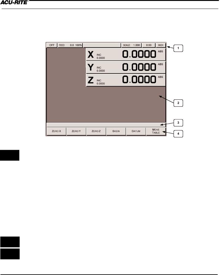
Screen Layout
The MILLPWR display screen is divided into four sections.
Status bar - displays the servo motor status (ON/OFF), feed rate, current tool, scale, job clock, and the current display setting (inches or millimeters).
 Information area - displays information about the job being performed.
•Readout (DRO) - used as a digital readout, the display will show the current position for each axis.
•Program (PGM) - when programming, a list of program steps (milling functions) and part-view graphics will be displayed.
•Calculator (CALC) - a TRIG, R.P.M., and geometry calculator are available to assist with calculating missing information. They can be used as stand-alone calculators or, while programming, the calculations can easily be returned to the program.
Message line - operator prompts and messages will appear here.
Softkeys - variable milling functions appear here; functions are selected by pressing the softkey directly below each category. When a key appears pressed, it is selected. When it appears “raised” it is not selected.
1-4 |
Operation Manual |

INTRODUCTION
MILLPWR®
Table Stop Button
The large red button located in the lower left corner on the front of the MILLPWR operator console is the TABLE STOP. In the event of a malfunction or programming error,
press the TABLE STOP button to turn off the servo motors. Turning off the servo motors will immediately stop all table movement.
WARNING
Pressing the TABLE STOP button will NOT stop the rotation of the cutting tool unless the machine has been configured to do so. In the event of an emergency, if the machine has not been wired to stop the rotation of the cutting tool, be prepared to raise the tool in addition to pressing the TABLE STOP button.
Conventions
Axis Conventions
Count Direction
When programming a part using MILLPWR, table movement and tool movement are determined by the use of positive or negative numbers. MILLPWR has been factory set with the following positive and negative count directions for the X, Y and Z-axes:
X-axis: The table will move to the left and the tool will move to the right for a positive count direction.
Y-axis: The table will move toward you while the tool moves away from you for a positive count direction.
Z-axis: The quill will move up (away from the table surface) for a positive count direction.
Operation Manual |
1-5 |
INTRODUCTION
MILLPWR®
Cartesian Coordinates
A cartesian coordinate is a position that can be measured from the X- and Y-axes.
Polar Coordinates
A polar coordinate is a position that is defined by an angle and a radius.
1-6 |
Operation Manual |
INTRODUCTION
MILLPWR®
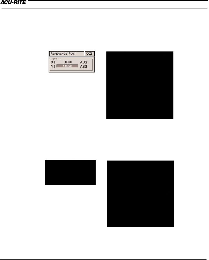
Absolute and Incremental Dimensions
Dimensions that you enter from a print are either absolute or incremental.
Absolute dimensions are measured from datum (also known as workpiece zero). Incremental dimensions are measured from one point to another.
Holes A and B are dimensioned using absolute values. Hole C is dimensioned incrementally from Hole A.
When entering these dimensions, we would say:
Hole A: Position/Drill |
002 |
X2.0000 ABS
Y1.5000 ABS
Hole B: Position/Drill |
003 |
X4.0000 ABS
Y1.5000 ABS
Hole C: Position/Drill |
004 |
|
X |
3.6250 INC |
002 - This indicates that the X position will increment |
Y |
1.5000 ABS |
from the X value in Step 2 (Hole A) above. |
Note: Both absolute and incremental dimensions may be used to define a position, as shown with Hole C.
It’s often easier to describe a location in terms of incremental dimensions rather than calculate its absolute coordinates.
Operation Manual |
1-7 |

INTRODUCTION
MILLPWR®
Saving, Backing Up, and Creating Directories for Programs
If you are creating a long program, don’t wait until the end to save your work.
Frequent saving reduces the risk of losing your work due to a power interruption.
When you create programs with MILLPWR, you can save them in any of three places—within MILLPWR's internal memory, on a 31/2" floppy disk, or on your PC. Saving your work means it will not be lost if MILLPWR is powered down or if there is a power interruption. As you save and back up your pro grams, you can neatly organize them in any of the following three main directories ("MILLPWR," "A:" and "REMTSTOR") or in personalized subdirectories that you can create.
is also equipped with a backup feature that enables you to make duplicate copies of your saved programs. We recommend that you back up your programs regularly to avoid accidental loss or other problems that may prevent you from recovering your original programs. Backing up programs takes only a few moments—and will save you valuable time if a problem does occur.
Note: Before you save or back up programs onto your PC, refer to Remote Storage and Setup for instructions.
For more details about how to save programs, back up files and create directories, refer to Programming.
1-8 |
Operation Manual |
DRO
MILLPWR®
DRO
Start Up
Power Up
Turn the power switch (located on the rear of the operator console) to “I.” The Power Indicator (located in the upper left corner of the operator console) will light up.
Screen Saver
Anytime the system is inactive for approximately 20 minutes, the LCD display will shut off, and a blank screen will appear. This screen saver function is designed to prolong the life of the operator console display. If the screen is blank, check that the Power Indicator light is illuminated. Press any key on the operator console or move the table and the display will reappear. If the Power Indicator light is not illuminated, then power to the MILLPWR system has been interrupted.
Operation Manual |
2-1 |

DRO
MILLPWR®
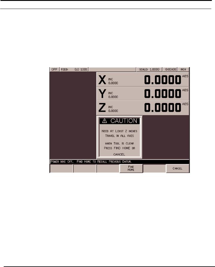
Finding Home
If you don't find home before moving the table, you will risk exceeding the table's travel limits and damaging the milling machine, MILLPWR or both.
You must find home before you run a program. To find home immediately after startup, press the FIND HOME softkey. Otherwise, press the DATUM softkey, then the FIND HOME softkey. The table will automatically move a few inches along the X- and Y-axes to find home.
Datum is a term used to describe "workpiece zero" or "absolute zero."
After you power up and find home, you
can quickly move to datum by pressing the POS key, followed by the GO key.
When finding home, MILLPWR will use ACU-RITE’s advanced Position-Trac™ technology. Position-Trac works by using a very precise distance-encrypted reference mark line pattern that's been placed onto each ACU-RITE precision glass scale included with the MILLPWR system. Proprietary software decodes the line pattern which then allows you to accurately find home and reestablish workpiece zero from any position.
With Position-Trac, there is no need to leave the system powered up when it is not being used. You will be able to easily, quickly and accurately reestablish workpiece zero immediately after you restart MILLPWR.
After home has been found, the tool’s position (relative to your most recent datum) will be displayed.
2-2 |
Operation Manual |
DRO
MILLPWR®
DRO Functions
The digital readout (DRO) display shows you the current tool position. While operating in the DRO mode, you can use several functions, such as skew and datum, to set up
a job. You can also use this as a normal DRO when you use your machine manually.
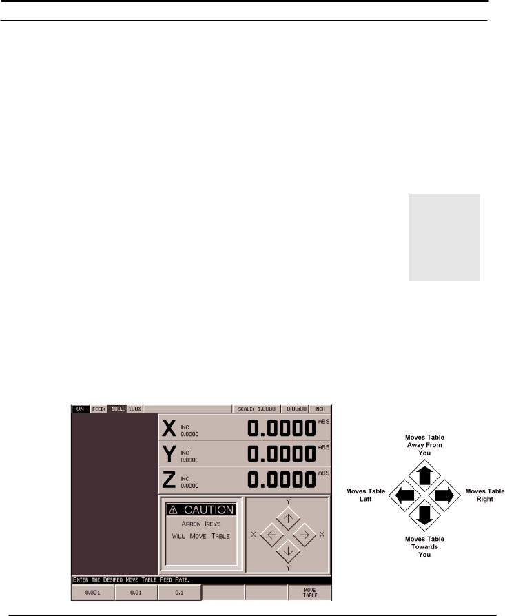
Move Table
The move table feature lets you move the table rapidly (or at an established feed rate) using the arrow keys.
•Press the MOVE TABLE softkey to turn the servo motors on. Press it again to turn them off.
•Enter the desired feed rate or skip this step to move at a rapid feed rate. Press the CLEAR key to enter a new feed rate.
It’s a good idea to fold in the handles before moving the table.
•If you want the arrow keys to move the table in increments, press
the 0.001, 0.01 or 0.1 softkey. (A different set of softkeys will appear if you are measuring in millimeters.)
•Move the table. You can move the X- and Y-axes simultaneously by pressing two arrow keys at the same time.
•Press the FEED+ and FEED- keys to adjust your feed rate.
Operation Manual |
2-3 |
DRO
MILLPWR®
Teach Position
Whenever an X, Y or Z coordinate is being entered the TEACH POSITION softkey will be available. Pressing this key will place the current absolute position in the coordinate entry field.
To “teach” MILLPWR a coordinate (while programming a milling function, such as a line):
As you are programming or using a milling function, you can switch between the DRO and PGM screens without losing the program.
•Using the arrow keys, highlight the X-, Y- or Z-axis field.
•Move the tool, indicator, or electronic edge finder to the position you want to teach.
•Press the TEACH POSITION softkey to enter that location and press ENTER. (With an electronic edge finder, the points will automatically be entered on contact—even if you over-travel.) See Using An Electronic Edge Finder.
·
·
Repeat the steps above for each axis and each location you want to
teach.
Press USE to accept the information or press CANCEL to return to the
previous screen without saving the information.
2-4 |
Operation Manual |

DRO
MILLPWR®
Using an Electronic Edge Finder
An ACU-RITE® Electronic Edge Finder can “teach” positions, find the center point of a circle, skew a part or locate datum (also known as workpiece zero) by simply “touching off” on the part. The greatest advantage of an electronic edge finder is that it instantly senses when contact is made allowing for over-travel.
MILLPWR SETUP PARAMETERS define the “Diameter” and “Unit” of measure (either inches or millimeters) for an electronic edge finder. Once this information has been entered, MILLPWR will automatically compensate for the radius of the tip of the electronic edge finder when performing any of the operations mentioned above.
To define the diameter and unit of measure:
•Press the SETUP key and highlight “Electronic Edge Finder.”
•Press the ENTER key.
•Enter a value for the edge finder’s diameter and unit of measure (inches or millimeters), then press the USE key.
•Press the USE NEW SETTINGS softkey.
To teach MILLPWR a coordinate, highlight the appropriate field then slowly move the table until the electronic edge finder touches the workpiece. When the electronic edge finder touches the part’s surface, the coordinate will appear in the data field. The electronic edge finder is active whenever an entry field is highlighted.
Operation Manual |
2-5 |
DRO
MILLPWR®
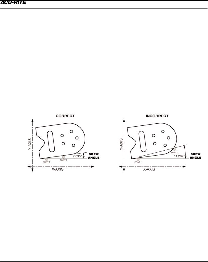
Skewing a Part
Save time setting up a job by skewing the part. The skew function automatically compensates for the angle offset of thepart. If a part is not perfectly parallel with either the X- or Y- axis, indicating it in is not necessary.
To skew a part, simply “touch off” on two or more points along one axis (either X or Y). Use an electronic edge finder to skew a part, or use a mechanical indicator and teach posi- tion—either way, it’s fast and easy.
Note: Choose a line to make parallel with the table’s X- or Y-axis—do not enter coordinates along a curve, along two different lines, or along a line that’s positioned at
a true 45 degree angle. MILLPWR will calculate the skew angle based upon a straight line between the points entered.
If you are working with a part that has a rough edge, it’s best to enter multiple points along the straightest edge so that can more accurately compensate for the skew angle.
Note: When two or more points are entered in the skew calculator MILLPWR will calculate the angle and adjust the X and Y plane. Angles that are less than 45° are adjusted
down to the X-axis, and angles greater than 45° adjust up to the Y-axis.
Note: The skew feature does not not work with G-code programs. Remove any skew angle prior to running a G-code program.
2-6 |
Operation Manual |

DRO
MILLPWR®
To skew a part or vise:
Using an electronic edge finder
•Press the SKEW softkey.
•Touch off on two or more points along any single straight edge of the part. Notice the “Points” and “Angle” change as
points are entered.
•Press the USE key to accept all of the points and return to the DRO screen. Press the CANCEL key to return to the DRO screen without accepting any points or affecting the previous skew angle.
The CLEAR ANGLE softkey will reset the number of points and the skew angle to zero.
Using teach position:
Here a workpiece was used as an example. You can also “touch off” on a vise or fixture.
•Press the SKEW softkey.
•Move the table so that a mechanical indicator rests against any straight edge on the part. Press the TEACH POSITION softkey to enter the coordinate. Notice that the “Points” change.
•Now move the table so that the mechanical indicator touches another point on the same straight edge. Press the TEACH POSITION softkey. Notice that
the “Points” and “Angle” change.
Repeat this process for any additional points.
•Press the USE key to accept all of the points and return to the DRO screen. Press the CANCEL key to return to the previous screen without affecting the previous skew angle.
The CLEAR ANGLE softkey will reset the number of points and the angle to zero.
Operation Manual |
2-7 |
DRO
MILLPWR®
Establishing Datum
Datum, also known as workpiece zero or absolute zero, is the point of reference that bases all of the part's coordinates from.
It is necessary to establish datum for every job. Datum's location may be indicated on a print; if it's not, establish a datum that enables most of the part's dimensions to be entered directly, with the least amount of calculations.
When establishing datum, you may find it easiest to locate a known point on each axis, such as the edge of the part or a location on the vise or fixture.
Refer to the procedure below as a basic guide for establishing datum. Decide to "touch off" using an electronic edge finder, a mechanical edge finder or a tool. Datum may be set at a point on the top surface or a position above or beneath the surface. X and Y datum may be set on an edge, or offset into or off of an edge, or where there's no material present (such as in the center of a circular part). There are many possibilities-- do what’s easiest for a particular job.
MILLPWR will retain datum even after the system has been powered down. (See Finding Home).
To establish datum:
Where and how datum is establish will vary from job to job. One of the most common methods of establishing datum is described below. Apply the same principles when setting datum for future jobs, making adjustments to the procedure as needed.
The following example will establish datum at the corner where the left, front and top surfaces of the part intersect. This is accomplished by "touching" each face with the tool used to cut the part.
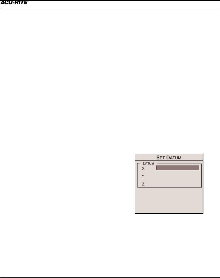
Define datum one axis at a time. Begin here with the X-axis:
•From the DRO screen, press the DATUM softkey.
•Insert the proper tool into the spindle.
2-8 |
Operation Manual |

DRO
MILLPWR®
•Position the tool so that it is near, but not touching, the left side of the part.
•Lower the tip of the tool so that it falls below the top surface of the part.
•Move the table along the X-axis slowly, while spinning the tool by hand. Pay close attention as the tool approaches the part— a subtle bump will be felt when they come into contact.
Stop the table at the moment the tool touches the part.
•Using the keypad, enter the radius of the tool (the distance from the center of the tool to the edge of the part). Be sure to specify if it’s a negative value.
Note: For this example, specify a negative value, because the tool's center is on the negative side of datum
(refer to Axis Conventions).
•Press the ENTER key.
Use the MOVE TABLE softkey to help with long table moves.
Now set datum for the Y-axis using the same procedure:
•Position the tool so that it is near, but not touching, the front face of the part. The tip of the tool should fall below the top surface of the part.
•Move the table along the Y-axis, slowly spinning the tool by hand. Pay close attention as the tool
approaches the part— A subtle bump will be felt when they make contact with each other. Stop the table at the moment the tool touches the part.
•Using the keypad, enter the radius of the tool into the"Y" field (be sure to specify if it is a negative value).
•Press the ENTER key.
Operation Manual |
2-9 |

DRO
MILLPWR®
Set datum for the Z-axis:
•Position the tool so that its tip touches the top surface of the part.
•Using the keypad, enter "0" into the "Z" field (or press the Z = 0 softkey).
•Press the ENTER key.
•Press the USE key.
Datum has now been established for X, Y, and Z
You can quickly move to Datum for X and Y by pressing the POS key. Check that your position is 0.0000 ABS
for both X and Y, then press the GO key.
It's a good idea to test the datum setting before programming. To confirm that the new datum is correct:
•Raise the tool and move the table until both the X- and Y-axes displays read "0.0000."
•Lower the tool until it touches the part.
•Check the tool's position—the lower left corner of the part should be directly beneath the center point of your tool.
•Now check the readout. If the Z-axis display says "0.0000," then the datum is accurate. If a value other than 0.0000 appears in the Z-axis display, repeat the procedure for establishing datum.
2-10 |
Operation Manual |

DRO
MILLPWR®
Hard Key Milling Functions
Most of the hard key milling functions can be used individually as one time milling routines without creating a program.
The one hard key milling function not used as
a one-time milling function is BLEND. The blend function inserts a connecting radius between two features (steps) in a program.
Hard key milling functions are ideal for jobs that only require one operation. Provide the required information once, and MILLPWR will “remember” it for each piece machined.
Example:
To drill the same bolthole pattern on several identical parts. Instead of creating a one-step program, save time by using the HOLES hard key milling function from the DRO screen.
•First, set up a tool and workpiece.
•From the DRO display, press the HOLES key, and select which hole pattern you want to drill from the available softkeys—ROW, FRAME, ARRAY, or BOLT CIRCLE.
•Enter the required information and press the GO key to machine the first part.
•Change the part. Press the HOLES key, then the pattern.
MILLPWR will automatically refer to the prior data entered for each part thereafter.
Operation Manual |
2-11 |

DRO
MILLPWR®
To change the hole pattern size, location or number of holes, press the HOLES key again. Now press the appropriate softkey, enter the new information and then press the
GO key.
This may also be applied to rectangles, circles, lines and arcs. The rectangle and circle milling functions require you to establish a tool offset. Lines and arcs only require a tool offset if the tool follows a left or right offset. It’s a good idea to set up a tool before using either of these function keys. Refer to Program Steps for a complete description of each function.
Note: The “Tool” setting on MILLPWR’s status bar (located at the top of the display) will indicate which tool has been selected. If the “Tool” status bar is blank, no tool has been selected.
2-12 |
Operation Manual |

PROGRAMMING
MILLPWR®
PROGRAMMING
Programming Considerations
"From" and "To" Points
Lines and arcs are defined by their “From” point (the point where they begin) and “To” point (the point where they end).
Depth of Cut
Since the Z-axis is not controlled by a servo motor, make changes to the depth of cut manually.
If the Z-axis depth is programmed, MILLPWR will preset the programmed value into the DRO. When it's time, MILLPWR will display the DRO screen and ask you to position the depth.
If you are not programming a depth, leave it set to 0.
Tool Offset
By using left and right offsets, dimensions can be programmed as identified on the print.
When a line, arc, frame, etc., is programmed, use the “Tool Offset” field to tell MILLPWR which side of the part the tool should be cutting on.
To determine which offset to use, picture yourself standing behind the tool as it is moving. If the tool is on the left side of the workpiece, use a "left" offset. If the tool is on the right side of the workpiece, use a "right" offset.
Operation Manual |
3-1 |
 Loading...