


 Loading...
User’s Manual
Conversational and g-code
CNC 3500i

Controls of the 3500i
Controls of the 3500i
Keys on visual display unit
Power control keys
Key |
Function |
|
NC Start key (i.e. run a program) |
|
|
|
Stop key (i.e. stop a program) |
|
|
|
Servo Reset activates servo motors |
|
|
Numerical keys |
|
|
|
Key |
Function |
|
Zero key |
|
|
|
One key |
|
|
|
Two key |
|
|
|
Three key |
|
|
|
Four key |
|
|
|
Five key |
|
|
|
Six key |
|
|
|
Seven key |
|
|
|
Eight key |
|
|
|
Nine key |
|
|
|
Decimal key |
|
|
Data Entry keys |
|
|
|
Key |
Function |
|
Plus - Minus toggle key |
|
|
|
CLEAR key clears selections, i.e. values, |
|
|
|
ENTER key activates selections, and |
|
entries |
|
|
Axis Keys |
|
|
|
Key |
Function |
|
X Axis |
|
|
|
Y Axis |
|
|
|
Z Axis |
|
|
|
U Axis |
Touch QWERTY keyboard
Key Board
Numeric Touch Pad(s)
Numeric Pad |
Calculator Pad |
ii
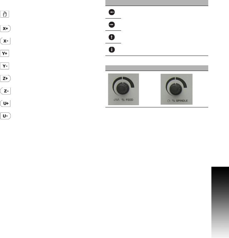
Axis Jog keys
Key |
Function |
|
JOG Cycles the CNC through manual |
|
movement modes: RAPID JOG, JOG |
|
FEED, JOG @ 100, JOG @ 10, JOG @ 1 |
|
|
|
Manually moves X+ axis in positive |
|
direction |
|
|
|
Manually moves X- axis in negative |
|
direction |
|
|
|
Manually moves Y+ axis in positive |
|
direction |
|
|
|
Manually moves Y- axis in negative |
|
direction |
|
|
|
Manually moves Z+ axis in positive |
|
direction |
|
|
|
Manually moves Z- axis in negative |
|
direction |
|
|
|
Manually moves U+ axis in positive |
|
direction |
|
|
|
Manually moves U- axis in negative |
|
direction |
|
|
Navigation keys
Key Function
ARROW over, up, down to move highlight
Potentiometer for feed rate and spindle speed override
Feed rate Spindle speed
Controls of the 3500i
ACU-RITE 3500i |
iii |

Controls of the 3500i
Keyboard Installation
The machine builder determines whether the system supports a keyboard option. If this option is supported, plug a USB keyboard into the 3500i.
There is no keyboard equivalent for the E-STOP, so emergency shutdowns cannot be performed through the keyboard.
Peripherals Supported:
USB memory devices; e.g. a memory stick.
USB pointing devices; e.g. a mouse.
USB Keyboards.
Keyboard Equivalent Key Strokes
Key |
Function |
CLEAR |
Alt + c |
|
|
ARROWS |
Arrows |
|
|
ENTER |
Enter |
|
|
X |
X |
|
|
Y |
Y |
|
|
Z |
Z |
|
|
U |
U |
|
|
START |
Alt + s |
|
|
HOLD |
Alt + h |
|
|
iv

Manual Information
Message symbols
This symbol indicates that there is one or more of the following risks when using the described function
Danger to work piece
Danger to fixtures
Danger to tool
Danger to machine
Danger to operators
Damage!
This symbol indicates that there is risk of damage, or electrical shock if instructions are not adhered to.
Different from machine to machine!
This symbol indicates that instructions may apply differently from one type of machine to another type of machine.
Refer to another Manual!
This symbol indicates that information required is located elsewhere (i.e. Machines Owner Manual).
Advice!
This symbol indicates that an Advice tip is being provided. Important, and/or additional information about the function described.
Fonts Used in this manual
3500i reference to the console KEYS
3500i reference to the touch screen Buttons
Changes (errors)
HEIDENHAIN Corporation is continuously striving to improve. Please help HEIDENHAIN Corporation by sending your request to the following e-mail address: sales@heidenhain.com
Visit www.acu-rite.com for latest version of this manual.
Manual Information
ACU-RITE 3500i |
v |

Manual Information
Model, Software and Features
This manual describes functions and features provided by 3500i as of the following NC software numbers.
CNC model |
NC software number |
ACU-RITE 3500i CNC Software |
689 871-01 |
|
|
The machine tool builder adapts the usable features of the CNC to his machine by setting machine parameters. Some of the functions described in this manual may therefore not be among the features provided by the CNC on your machine tool.
CNC functions that may not be available on your machine include:
Tool measurement with touch probes
The machine tool builder representative can assist with becoming familiar with the features of the machine.
Many machine manufacturers, as well as HEIDENHAIN Corp., offer programming courses for the CNC. We recommend these courses as an effective way of improving your programming skill and sharing information and ideas with other CNC users.
Intended place of operation
The CNC is intended for use primarily in industrially-zoned areas. Refer to the respective installation manual for additional information.
vi

New Functions of Software
689 871-01-02
CAM now includes a Save button to allow quickly saving progress. Ctrl-S can now be used as well.
CAM geometry creation dialogs now support copying and pasting between dialogs.
ARC Help Forms now support all planes. As such, X, Y, and Z parameters are all available and indicated as optional. User needs to decide which of these are actually required for the particular instance.
The Edit Preview Features menu now includes a button to access the Simulation Tool Table.
Tool and Offset Tables now support copying in both directions; from Simulation to NC, and from NC to Simulation.
The use of the Sim Tool and Sim Offset tables are now configurable See "Simulation Tool and Offset Tables" on page 71.
689 871-01-09
Added a new feature for custom OEMTEMPLATE program template files. See "To create custom program templates:" on page 99.
Manual Information
ACU-RITE 3500i |
vii |

Manual Information
Changed Functions of Software
689 871-01-01
Feed & Speed Calculator in MDI was changed; see page 55.
Feeds & Speeds Table functionality and description was expanded; see page 68.
Additional information for the Repeat blocks feature is being provided; see page 147.
689 871-01-02
Linear and Arc Engraving cycles now apply active program rotation. Mirroring and scaling are still cancelled at the start of the cycle. No rotation, mirroring, or scaling is active after these cycles have run, and would need to be reprogrammed if desired; see page 110.
Tool Table Teach and Teach Program buttons are now configurable as to their positions on the menu; see page 66.
The setting to hide or show the on-screen keyboard is now persistent across machine power cycles; see page 13.
689 871-01-03
Rotation cycles (G68 and RMS) now allow user to specify if the rotation center is a pivot point for the rotation or not; see page 239.
A circle of the format XYR with start=end now generates an error because it cannot be properly calculated; see page 134.
The M98 Help Form now includes the previously missing Loop parameter; see page 238.
689 871-01-04
The Conversational Editor now always ensures that a blank line exists at the end of programs, in order to make it easy to insert new blocks at the end of the program; see page 112.
When turning OFF Edit Preview, the active program preview run is now cancelled. Also, the Preview Features menu is now available while the program preview is running; see page 116.
689 871-01-05
Added description of estimated machining time in preview image; see page 93.
Outdated estimated machining times are now displayed on the preview image in RED colored text; see page 93.
689 871-01-08
Corrected total number of available tools (100); see page 61.
Additional information has been added for islands; see page 192.
Added examples of pockets with islands; see page 241.
689 871-01-09
Pocket cycles now allow changing the direction of the Roughing Pass, and as such the previous 'FinishDir' parameter has been superseded by a new 'Direction' parameter, which now applies to both the Roughing and Finishing passes; see page 171
viii

Contents
Introduction
Machining Fundamentals
Manual Data Input
Tool Management
Program Management
Conversational Editing
Programming: Canned Cycles, subprograms
Drawing Programs
Running a Program on the Machine
CAM: Programming
G-code Edit, Help, & Advanced Features
Software Update
1
2
3
4
5
6
7
8
9
10
11
12
ACU-RITE 3500i |
ix |

x
Table of Contents
Controls of the 3500i
Keys on visual display unit ....................................................................................... |
iv |
Numerical keys ........................................................................................................ |
iv |
Data Entry keys........................................................................................................ |
iv |
Axis Keys ................................................................................................................. |
iv |
Touch QWERTY keyboard ....................................................................................... |
iv |
Numeric Touch Pad(s).............................................................................................. |
iv |
Axis Jog keys............................................................................................................ |
v |
Navigation keys......................................................................................................... |
v |
Potentiometer for feed rate and spindle speed override .......................................... |
v |
Keyboard Installation................................................................................................ |
vi |
Keyboard Equivalent Key Strokes ............................................................................ |
vi |
Manual Information
Message symbols................................................................................................... |
vii |
Fonts Used in this manual ................................................................................. |
vii |
Model, Software and Features .............................................................................. |
viii |
Intended place of operation .............................................................................. |
viii |
New Functions of Software..................................................................................... |
ix |
689 871-01-02..................................................................................................... |
ix |
689 871-01-09..................................................................................................... |
ix |
Changed Functions of Software ............................................................................... |
x |
689 871-01-01...................................................................................................... |
x |
689 871-01-02...................................................................................................... |
x |
689 871-01-03...................................................................................................... |
x |
689 871-01-04...................................................................................................... |
x |
689 871-01-05...................................................................................................... |
x |
689 871-01-08...................................................................................................... |
x |
689 871-01-09...................................................................................................... |
x |
Introduction
1.1 The 3500i
ACU-RITE conversational, and G-code formats ....................................................... |
2 |
Powering Up the CNC Machine............................................................................... |
3 |
E-Stop, Servo Reset, and CNC Shutdown ............................................................... |
4 |
Writing Programs..................................................................................................... |
5 |
3500i |
xi |
1.2 |
Visual Display Unit |
|
|
Operating Panel with Touch Screen display ............................................................ |
6 |
|
Screen Navigation.................................................................................................... |
6 |
|
Menus, Dialogues, and Forms................................................................................. |
7 |
|
General Operating Guidelines.................................................................................. |
8 |
|
Main Operating Modes....................................................................................... |
8 |
|
Sub Modes ......................................................................................................... |
9 |
|
Upper Menu and Status Information Bar.......................................................... |
10 |
|
Machine function buttons................................................................................. |
11 |
|
Keyboard........................................................................................................... |
12 |
|
Additional Buttons ............................................................................................ |
13 |
|
Special Characters ............................................................................................ |
13 |
|
Programming Sliders ........................................................................................ |
14 |
|
Numeric touch pad ........................................................................................... |
15 |
|
Calculator .......................................................................................................... |
16 |
|
Advanced Function buttons .............................................................................. |
16 |
|
Context Sensitive Help .......................................................................................... |
17 |
|
Using Context Sensitive Help ........................................................................... |
17 |
|
Console Key Pad.................................................................................................... |
19 |
1.3 Main Operating Mode Screens |
|
|
|
Display navigation .................................................................................................. |
20 |
|
Manual Data Input ................................................................................................. |
20 |
|
Program Management Screen............................................................................... |
21 |
|
Program Run.......................................................................................................... |
22 |
1.4 |
Accessories: |
|
|
Touch probes ......................................................................................................... |
23 |
|
HR electronic hand wheels.................................................................................... |
24 |
|
Electronic Edge Finder........................................................................................... |
24 |
Machining Fundamentals |
|
|
2.1 |
Fundamentals of Positioning |
|
|
Position encoders and reference marks ................................................................ |
26 |
|
Reference system ................................................................................................. |
27 |
|
Reference system on milling machines................................................................. |
27 |
|
Designation of the axes on milling machines ........................................................ |
28 |
|
Polar coordinates ................................................................................................... |
28 |
|
Setting the pole and the angle reference axis .................................................. |
29 |
|
Absolute and incremental polar coordinates..................................................... |
29 |
|
Angle Measurements ....................................................................................... |
30 |
xii
Absolute and incremental work piece positions .................................................... |
31 |
Absolute work piece positions.......................................................................... |
31 |
Incremental work piece positions ..................................................................... |
31 |
Setting the datum .................................................................................................. |
32 |
Fixture Offsets .................................................................................................. |
32 |
2.2 Manual Machine Positioning |
|
Jog Mode Moves................................................................................................... |
34 |
Changing the Jog Mode.................................................................................... |
34 |
Incremental Moves ........................................................................................... |
34 |
Continuous Moves............................................................................................ |
34 |
Adjusting the Feedrate...................................................................................... |
35 |
Overriding the Spindle RPM .................................................................................. |
35 |
Manual Data Input |
|
3.1 Manual Data Input (MDI) |
|
Overview ............................................................................................................... |
38 |
Manual Data Input Screen ..................................................................................... |
38 |
Manual Data Input Mode Settings......................................................................... |
39 |
Manual Data Input Menu Bar................................................................................. |
40 |
MDI Menu Page two ........................................................................................ |
41 |
Manual Data Input Operations............................................................................... |
42 |
Manual Data Input Cycles...................................................................................... |
44 |
Pocket Cycle Example ...................................................................................... |
45 |
Block History.......................................................................................................... |
47 |
G-code MDI .......................................................................................................... |
48 |
MDI Touch Screen Feature Dialogues .................................................................. |
49 |
Zero Axes.......................................................................................................... |
49 |
Program Preset ................................................................................................. |
50 |
Move to Target Location................................................................................... |
51 |
Tool ................................................................................................................... |
52 |
Offset................................................................................................................ |
53 |
Basic Modals..................................................................................................... |
54 |
Feed and Speed................................................................................................ |
55 |
MDI Teach ............................................................................................................. |
57 |
3500i |
xiii |
Tool Management |
|
|
4.1 |
Tool Table |
|
|
Tool Table / Tool Management .............................................................................. |
60 |
|
Tool Compensation Required Data ........................................................................ |
60 |
|
Tool numbers / Tool names ................................................................................... |
61 |
|
Locating the Tool Table.......................................................................................... |
61 |
|
Editing the tool table.............................................................................................. |
62 |
|
Tool Table Menu Bar......................................................................................... |
62 |
|
Second Menu Bar ............................................................................................. |
63 |
|
Clearing an entire line of tool data .................................................................... |
64 |
|
Clearing the current tool table .......................................................................... |
64 |
|
Find ................................................................................................................... |
65 |
|
Finding a tool using text.................................................................................... |
65 |
|
Clear Feature .................................................................................................... |
66 |
|
Teach, and Teach Program ............................................................................... |
66 |
|
Tool Table Structure .............................................................................................. |
67 |
|
Tool table: Standard tool data ........................................................................... |
67 |
|
Feeds & Speeds Table........................................................................................... |
68 |
|
Feeds & Speeds Overview ............................................................................... |
68 |
|
Feeds & Speeds Table Structure ...................................................................... |
68 |
|
Using the Feeds & Speeds Table ..................................................................... |
70 |
|
Simulation Tool and Offset Tables......................................................................... |
71 |
4.2 |
Tool Data |
|
|
T-Codes, and Tool Activation ................................................................................. |
72 |
|
Activating Offsets via the Program........................................................................ |
72 |
|
Tool-Length Offsets............................................................................................... |
73 |
|
Entering Tool Length Offsets in the Tool Table ................................................ |
73 |
|
Diameter Offset in Tool Table................................................................................ |
74 |
|
Tool Radius Compensation .................................................................................... |
75 |
|
Contouring without radius compensation......................................................... |
75 |
|
Contouring with radius compensation .............................................................. |
76 |
|
Radius compensation: Machining corners........................................................ |
77 |
|
Ramping into a Compensation Move ............................................................... |
78 |
|
Line Tangent Entry Move ................................................................................. |
78 |
|
Line Perpendicular Entry Move......................................................................... |
78 |
|
Arc Tangent Entry Move................................................................................... |
79 |
|
Line Arc Tangent Entry Move ........................................................................... |
79 |
|
Special Code: Temporary Change of Tool Diameter......................................... |
80 |
xiv
|
Tool Compensation Path........................................................................................ |
81 |
|
Path of Tool During Tool Compensation ........................................................... |
81 |
|
Intersecting Points ............................................................................................ |
82 |
|
Compensation Around Acute Angles................................................................ |
82 |
|
General Precautions............................................................................................... |
83 |
|
Fixture Offsets - Tool menu................................................................................... |
84 |
|
Tool Life Management........................................................................................... |
84 |
|
Activate Tool Life Management........................................................................ |
84 |
|
Lock, or Unlock a Tool....................................................................................... |
85 |
|
Replacement Tool (RT)...................................................................................... |
85 |
Program Management |
|
|
5.1 |
Program Management Introduction |
|
|
Accessing Program Management ......................................................................... |
88 |
|
Program Screen Description.................................................................................. |
88 |
|
Program Manager Menu Bar ................................................................................. |
89 |
|
Utility Function Buttons ......................................................................................... |
90 |
|
Display window arrangement ................................................................................ |
91 |
5.2 |
Program Manager Functions |
|
|
Folder Filter............................................................................................................ |
92 |
|
Advanced Folder Filter ........................................................................................... |
92 |
|
Utility Button Functions ......................................................................................... |
93 |
|
Sorting Folder Contents......................................................................................... |
95 |
|
Program Properties................................................................................................ |
95 |
|
Recycle Bin ............................................................................................................ |
96 |
|
USB Access ........................................................................................................... |
96 |
5.3 Creating, Editing, & Selecting to Run |
|
|
|
Creating a New Part Program ................................................................................ |
97 |
|
Editing an Existing Part Program ........................................................................... |
97 |
|
Selecting a Program To Run .................................................................................. |
98 |
|
Program selection: ............................................................................................ |
98 |
|
Using custom program templates ......................................................................... |
99 |
|
To create custom program templates:.............................................................. |
99 |
3500i |
xv |
Conversational Editing |
|
|
6.1 |
Conversational Programming |
|
|
Getting Started .................................................................................................... |
102 |
|
Program Edit Screen............................................................................................ |
103 |
|
Program Edit buttons...................................................................................... |
104 |
|
Conversational Data Input Cycles ........................................................................ |
105 |
|
Milling Button ................................................................................................. |
105 |
|
Milling Feature Buttons .................................................................................. |
106 |
|
More Milling Button........................................................................................ |
107 |
|
Drill Features Button....................................................................................... |
108 |
|
Pocket Cycles Button ..................................................................................... |
109 |
|
Other Cycles Button ....................................................................................... |
110 |
|
Program Editing ................................................................................................... |
111 |
|
Mark a program block: .................................................................................... |
111 |
|
Unmark a block, or blocks:.............................................................................. |
111 |
|
Deleting a program block:............................................................................... |
112 |
|
Inserting a program block: .............................................................................. |
112 |
|
Copy/Paste Blocks in a program ..................................................................... |
113 |
|
Moving Blocks in a program ........................................................................... |
113 |
|
Canceling edits to a program block:................................................................ |
113 |
|
Restore edits to a program block:................................................................... |
114 |
|
Editing an existing block: ................................................................................ |
114 |
|
Inserting program blocks using keypad hotkeys:............................................ |
114 |
|
Program Text Editing ........................................................................................... |
115 |
|
Find: Specific Text or Code in a program........................................................ |
115 |
|
Program Edit Preview .......................................................................................... |
116 |
|
Preview Side Bar Menu .................................................................................. |
116 |
|
Preview Features Menu ................................................................................. |
117 |
|
Program / Display Relation................................................................................... |
118 |
Programming: Canned Cycles, sub-programs |
|
|
7.1 |
Explaining Basic Cycles |
|
|
Round/Chamfer.................................................................................................... |
120 |
|
Corner Rounding............................................................................................. |
120 |
|
Line-to-Line Corner Rounding ......................................................................... |
120 |
|
Line-to-Arc Corner Rounding .......................................................................... |
121 |
|
Arc-to-Arc Corner Rounding............................................................................ |
121 |
|
Chamfering ..................................................................................................... |
121 |
xvi
Rapid.................................................................................................................... |
122 |
Rapid Move..................................................................................................... |
122 |
Rapid Move - EndPoint: .................................................................................. |
122 |
Rapid Move - Angle and Radius: ..................................................................... |
123 |
Rapid Move - Angle and X:.............................................................................. |
123 |
Rapid Move - Angle and Y:.............................................................................. |
124 |
Rapid Move - Radius and X: ............................................................................ |
124 |
Rapid Move - Radius and Y: ............................................................................ |
125 |
Line ...................................................................................................................... |
125 |
Line Move: ...................................................................................................... |
125 |
Line Move - EndPoint:..................................................................................... |
126 |
Line Move - Angle and Radius: ....................................................................... |
127 |
Line Move - Angle and X:................................................................................ |
127 |
Line Move - Angle and Y:................................................................................ |
128 |
Line Move - Radius and X: .............................................................................. |
128 |
Line Move - Radius and Y: .............................................................................. |
129 |
Arc ....................................................................................................................... |
130 |
Arc Move: ....................................................................................................... |
130 |
Arc Move - Radius and EndPoint: ................................................................... |
131 |
Arc Move - Center and EndPoint: ................................................................... |
132 |
Arc Move - Center and Angle:......................................................................... |
133 |
Using Arc Center and EndPoint to create a circle ........................................... |
134 |
Arc Move - Center and Angle, Absolute mode: .............................................. |
134 |
Arc Move - Center and Angle, Incremental mode: ......................................... |
134 |
Dwell:................................................................................................................... |
135 |
Plane Selection .................................................................................................... |
136 |
Reference Point Return: ...................................................................................... |
137 |
Fixture Offset (Work Coordinate System Select):................................................ |
138 |
Unit (Inch/MM)..................................................................................................... |
139 |
Dimension (Abs/Inc)............................................................................................. |
139 |
Absolute Zero Set ................................................................................................ |
140 |
Block Form........................................................................................................... |
141 |
Temporary Path Tolerance................................................................................... |
142 |
System Data ........................................................................................................ |
143 |
FeedRate ............................................................................................................. |
144 |
FeedRate (4th-Axis) ............................................................................................. |
144 |
Spindle RPM ........................................................................................................ |
145 |
M - Functions....................................................................................................... |
145 |
Tool Definition and Activation .............................................................................. |
146 |
Repeat Blocks...................................................................................................... |
147 |
3500i |
xvii |
7.2 Canned Cycles |
|
Canned Cycles ..................................................................................................... |
149 |
Drilling Cycles ...................................................................................................... |
150 |
Drilling, Tapping, and Boring ........................................................................... |
150 |
Basic Drill Cycle .............................................................................................. |
150 |
Counterbore Drill Cycle................................................................................... |
151 |
Peck Drill Cycle ............................................................................................... |
151 |
Tapping Cycle ................................................................................................. |
152 |
Boring Bidirectional Cycle ............................................................................... |
153 |
Boring Unidirectional Cycle............................................................................. |
153 |
Chip Break Cycle............................................................................................. |
154 |
Flat Bottom Boring Cycle................................................................................ |
155 |
Drill Bolt Hole Cycle ........................................................................................ |
156 |
Drill Pattern Cycle ........................................................................................... |
157 |
Milling Cycles....................................................................................................... |
158 |
Mill Cycle ....................................................................................................... |
158 |
EndMill Cycle .................................................................................................. |
160 |
Face Mill Cycle................................................................................................ |
161 |
Hole Mill Cycle................................................................................................ |
163 |
Thread Mill Cycle ............................................................................................ |
164 |
Circular Profile Cycle....................................................................................... |
167 |
Rectangular Profile Cycle................................................................................ |
169 |
Pocket Cycles ...................................................................................................... |
171 |
Pocket Cycle Overview: ................................................................................. |
171 |
Draft Angle Pocket Cycle................................................................................ |
172 |
Rectangular Pocket Cycle ............................................................................... |
174 |
Circular Pocket Cycle ...................................................................................... |
176 |
Plunge Rectangular Pocket Cycle ................................................................... |
178 |
Plunge Circular Pocket Cycle .......................................................................... |
180 |
Frame Pocket Cycle........................................................................................ |
182 |
Ring Pocket Cycle........................................................................................... |
184 |
Slot Cycle........................................................................................................ |
186 |
Circular Slot Cycle........................................................................................... |
188 |
Irregular Pocket Cycle .................................................................................... |
190 |
Islands............................................................................................................. |
192 |
Bottom Finish ................................................................................................. |
193 |
Side Finish ..................................................................................................... |
194 |
Engraving Cycles ................................................................................................. |
195 |
Programming the Engrave Cycle .................................................................... |
195 |
Programming the Arc Engrave Cycle.............................................................. |
197 |
xviii
7.3 |
Probing Cycles |
|
|
Tool, and Spindle Probe cycles ............................................................................ |
199 |
|
Tool Probe Cycles ................................................................................................ |
200 |
|
Tool Probe Calibration Cycle ........................................................................... |
201 |
|
Tool Length and Diameter Offset Preset........................................................ |
203 |
|
Manual Tool-Length Offset Preset.................................................................. |
210 |
|
Manual Tool Diameter Measure for Special Tools .......................................... |
213 |
|
Tool Breakage, Length and Diameter Wear Detection .................................. |
216 |
|
Spindle Probe....................................................................................................... |
219 |
|
Spindle Probe Cycles ...................................................................................... |
219 |
|
Spindle Probe Settings.................................................................................... |
219 |
|
Spindle Probe Calibration Cycle ...................................................................... |
220 |
|
Edge Finding ................................................................................................... |
222 |
|
Outside Corner Finding .................................................................................. |
223 |
|
Inside Corner Finding ..................................................................................... |
225 |
|
Inside/Outside Boss/Hole Finding .................................................................. |
227 |
|
Inside/Outside Web Finding ........................................................................... |
229 |
|
Protected Probe Positioning .......................................................................... |
231 |
|
Skew Compensation ...................................................................................... |
232 |
|
Using the Z Work Offset Update Feature ....................................................... |
235 |
7.4 |
Sub-programs |
|
|
Sub-program information: .................................................................................... |
236 |
|
Overview......................................................................................................... |
236 |
|
Ending the Main Program ............................................................................... |
236 |
|
Defining a sub-program ....................................................................................... |
237 |
|
Ending a sub-program.......................................................................................... |
237 |
|
Calling a sub-program .......................................................................................... |
237 |
|
Looping a sub-program ........................................................................................ |
238 |
|
Rotate, Mirror, and/or Scale a sub-program......................................................... |
239 |
|
Pocket and Islands example ................................................................................ |
241 |
|
Pocket/Island example 1 ................................................................................. |
241 |
|
Pocket/Island example 2 ................................................................................. |
243 |
|
Pocket/Island example 3 ................................................................................. |
245 |
|
Pocket/Island example 4 ................................................................................. |
247 |
|
Pocket/Island example 5 ................................................................................. |
249 |
|
Pocket/Island example 6 ................................................................................. |
251 |
3500i |
xix |
Drawing Programs |
|
|
8.1 |
Draw |
|
|
Viewing Programs ............................................................................................... |
256 |
|
Starting Draw....................................................................................................... |
257 |
|
View Options Menu............................................................................................. |
258 |
|
Adjust View Menu ............................................................................................... |
259 |
|
Adjust Block Form ............................................................................................... |
260 |
|
Zoom.................................................................................................................... |
260 |
|
Rotate Drawing View........................................................................................... |
261 |
|
Pan Drawing View ............................................................................................... |
261 |
|
Line View Adjustments........................................................................................ |
262 |
|
Draw Options....................................................................................................... |
263 |
|
Sim Tools ............................................................................................................. |
264 |
Running a Program on the Machine |
|
|
9.1 |
Running a program |
|
|
Modes of Programmed Operation....................................................................... |
266 |
|
Auto mode ........................................................................................................... |
266 |
|
Starting a program .......................................................................................... |
267 |
|
Pause, or Stop a running program .................................................................. |
267 |
|
Clearing a Messages ........................................................................................... |
267 |
|
Single Step........................................................................................................... |
268 |
|
Block Search ........................................................................................................ |
269 |
|
Select a Starting Block.................................................................................... |
269 |
|
Using Draw with running programs..................................................................... |
270 |
|
Program Status Area............................................................................................ |
271 |
|
Parts Counter....................................................................................................... |
272 |
|
Program Run Timers............................................................................................ |
273 |
|
Accessing the Tool Table..................................................................................... |
273 |
|
Axis Jog keys....................................................................................................... |
274 |
|
In-Program Axis Jogging...................................................................................... |
275 |
CAM: Programming |
|
|
10.1 |
CAM Programming |
|
|
CAM Mode .......................................................................................................... |
278 |
|
Recommended CAM Programming Sequence ................................................... |
279 |
|
CAM Setup ..................................................................................................... |
279 |
|
Geometry Data .............................................................................................. |
279 |
|
Job Setup........................................................................................................ |
279 |
xx
CNC Program .................................................................................................. |
279 |
CAM Mode Mouse Operations ........................................................................... |
280 |
CAM Mode Screen .............................................................................................. |
281 |
Activating CAM Mode ......................................................................................... |
281 |
Creating a New Program ..................................................................................... |
282 |
CAM Mode buttons ........................................................................................ |
282 |
Geometry Toolbar buttons: ............................................................................. |
282 |
Point Tool buttons........................................................................................... |
283 |
Point Editing.................................................................................................... |
283 |
Line Tool buttons ............................................................................................ |
284 |
Editing a Line .................................................................................................. |
285 |
Circle Tool buttons .......................................................................................... |
286 |
Circle Editing ................................................................................................... |
286 |
Shape Tool buttons ......................................................................................... |
287 |
Tool Path Buttons ........................................................................................... |
288 |
Tool Path Data Input ............................................................................................ |
289 |
Quick Coordinate Entry........................................................................................ |
290 |
Job Setup: Basic tab ............................................................................................ |
291 |
Basic tab Data Entries .................................................................................... |
291 |
Job Setup: Advanced tab.................................................................................... |
293 |
Advanced tab Data Entries.............................................................................. |
293 |
Comment Tab ...................................................................................................... |
294 |
Block Form: Basic tab .......................................................................................... |
295 |
Basic tab Data Entries..................................................................................... |
295 |
Comment Tab ...................................................................................................... |
295 |
Drilling Cycle: ....................................................................................................... |
296 |
Drill Cycle: Basic ............................................................................................ |
296 |
Drill Cycle: Counterbore ................................................................................. |
296 |
Drill Cycle: Peck .............................................................................................. |
296 |
Drill Cycle: Tapping ......................................................................................... |
296 |
Drill Cycle: Boring Bidirectional ....................................................................... |
296 |
Drill Cycle: Boring Unidirectional..................................................................... |
297 |
Drill Cycle: Chip Break..................................................................................... |
297 |
Drill Cycle: Flat Bottom Boring........................................................................ |
297 |
Drilling dialogue: .................................................................................................. |
298 |
Basic tab ......................................................................................................... |
298 |
Setup tab:........................................................................................................ |
299 |
Bolt Hole tab: .................................................................................................. |
299 |
Pattern tab: ..................................................................................................... |
300 |
Comment tab: ................................................................................................. |
300 |
Mill Cycle ............................................................................................................. |
301 |
Basic tab: ........................................................................................................ |
301 |
Setup tab:........................................................................................................ |
302 |
3500i |
xxi |
Pocket Cycle ........................................................................................................ |
303 |
Basic tab: ........................................................................................................ |
303 |
Setup tab: ....................................................................................................... |
303 |
Pocket Finish Cycles............................................................................................ |
305 |
Bottom tab:..................................................................................................... |
305 |
Side tab:.......................................................................................................... |
305 |
Adding a Machining Side: ............................................................................... |
306 |
Engraving Cycle ................................................................................................... |
307 |
Basic tab: ........................................................................................................ |
307 |
Setup tab: ....................................................................................................... |
308 |
Comment tab:................................................................................................. |
308 |
Program Directive ................................................................................................ |
308 |
Adding a Program Directive ............................................................................ |
308 |
Modifying Toolbar ................................................................................................ |
309 |
Modifying Tools Buttons:................................................................................ |
309 |
Viewing Tools ...................................................................................................... |
310 |
Viewing Tool Buttons:..................................................................................... |
310 |
CAM Mode buttons ............................................................................................. |
311 |
CAM Tool Buttons: ......................................................................................... |
311 |
CAM Setup .......................................................................................................... |
313 |
Selection tab: .................................................................................................. |
313 |
Output tab:...................................................................................................... |
313 |
Display tab: ..................................................................................................... |
314 |
Tool Table tab: ................................................................................................ |
314 |
View Buttons: ................................................................................................. |
315 |
Geometry............................................................................................................. |
316 |
Defining Geometry: ........................................................................................ |
316 |
Completing the Geometry: ............................................................................. |
317 |
Finalizing the geometry................................................................................... |
319 |
Creating the shape.......................................................................................... |
320 |
DXF Import Feature ............................................................................................. |
321 |
DXF Entities Supported .................................................................................. |
321 |
DXF Entities Not Supported............................................................................ |
321 |
Importing a DXF File ....................................................................................... |
321 |
Modifying Tools ................................................................................................... |
322 |
Corner Radius (inserting) ................................................................................ |
322 |
Chamfer (inserting) ......................................................................................... |
322 |
Trimming Geometry........................................................................................ |
323 |
Delete button.................................................................................................. |
323 |
Properties button ............................................................................................ |
323 |
Shapes ................................................................................................................. |
324 |
Copying a Shape ............................................................................................. |
324 |
Moving a Shape .............................................................................................. |
324 |
xxii
Tool Table ............................................................................................................ |
325 |
Setting up the Tool Table................................................................................ |
327 |
Importing a Tool Table .................................................................................... |
327 |
Exporting a Tool Table..................................................................................... |
327 |
Tool Paths ............................................................................................................ |
328 |
Creating a Tool Path in CAM Mode ................................................................ |
328 |
Tool Path Verification ...................................................................................... |
328 |
Tool Path Editing............................................................................................. |
329 |
Use Existing Shape......................................................................................... |
329 |
Editing a Tool Path .......................................................................................... |
330 |
Disabling, and Enabling Tool Paths ................................................................. |
330 |
Deleting Tool Paths......................................................................................... |
330 |
Arranging Tool Paths Sequence...................................................................... |
330 |
Smart Programming........................................................................................ |
331 |
Files Created................................................................................................... |
331 |
CAM Example 1................................................................................................... |
332 |
Exercise One:.................................................................................................. |
332 |
Defining Geometry:......................................................................................... |
332 |
Connecting the Geometry:.............................................................................. |
334 |
Finalizing the geometry................................................................................... |
335 |
Creating the shape.......................................................................................... |
336 |
Creating the tool paths:................................................................................... |
337 |
CAM Example 2................................................................................................... |
341 |
Example Two: ................................................................................................. |
341 |
Create Circle Geometry: ................................................................................. |
341 |
Create Line Geometry..................................................................................... |
343 |
Finalizing the geometry................................................................................... |
344 |
Creating the shape.......................................................................................... |
345 |
Creating the tool paths:................................................................................... |
346 |
G-Code Edit, Help, & Advanced Features |
|
11.1 G-Code Program Editing |
|
Activating Edit Mode ........................................................................................... |
352 |
Program Edit Screen............................................................................................ |
353 |
Program Edit buttons ...................................................................................... |
354 |
Edit Features menu......................................................................................... |
355 |
Preview Features menu.................................................................................. |
356 |
Program Editing ................................................................................................... |
357 |
Mark a program block: .................................................................................... |
357 |
Unmark a block, or blocks:.............................................................................. |
357 |
Delete a Character: ......................................................................................... |
358 |
Deleting a program block: ............................................................................... |
358 |
Inserting a program block: .............................................................................. |
359 |
Copy/Paste Blocks in a program ..................................................................... |
359 |
Moving Blocks in a program ........................................................................... |
360 |
3500i |
xxiii |
|
Canceling edits to a program block:................................................................ |
360 |
|
Restore edits to a program block:................................................................... |
360 |
|
Program Text Editing ........................................................................................... |
361 |
|
Inserting Text:................................................................................................. |
361 |
|
Overwriting Text: ............................................................................................ |
361 |
|
Find: Specific Text or Code in a program........................................................ |
362 |
|
Replace: Specific Text, or Code in a program................................................. |
363 |
|
Preview Features................................................................................................. |
364 |
|
Edit Features Menu ........................................................................................ |
364 |
|
Program / Display Relation................................................................................... |
365 |
|
Edit Help Preview .......................................................................................... |
365 |
11.2 G-Code and M-Code Definitions |
|
|
|
G-Code................................................................................................................. |
366 |
|
M-Code Definition................................................................................................ |
370 |
|
Typing in Address Words..................................................................................... |
371 |
|
Typing in M-Codes............................................................................................... |
371 |
11.3 |
Edit Help |
|
|
Activating Edit Help ............................................................................................. |
372 |
|
Help Graphic Screens .......................................................................................... |
373 |
|
G - Functions........................................................................................................ |
374 |
|
Basic Modal Functions.................................................................................... |
375 |
|
Multi -Segment Blocks ................................................................................... |
375 |
|
Arcs................................................................................................................. |
376 |
|
Drilling Cycles ................................................................................................. |
376 |
|
Pocket Cycles ................................................................................................. |
377 |
|
Milling and Profiles ......................................................................................... |
377 |
|
Rotation, Scaling, and Mirroring...................................................................... |
378 |
|
Spindle Probing............................................................................................... |
378 |
|
Tool Probing.................................................................................................... |
379 |
|
Tool Radius Compensation ............................................................................. |
379 |
|
Other G - Functions ........................................................................................ |
380 |
|
M - Functions....................................................................................................... |
381 |
|
All M - Functions............................................................................................. |
381 |
|
Basic M - Functions ........................................................................................ |
382 |
|
Cooling, Cleaning, and Lubrication.................................................................. |
382 |
|
Spindle Functions ........................................................................................... |
383 |
|
Tool Change.................................................................................................... |
383 |
11.4 |
Advanced Programming |
|
|
SPEED ................................................................................................................. |
384 |
|
M - Functions....................................................................................................... |
384 |
|
Miscellaneous (M-Code) ................................................................................. |
384 |
|
Control M - Codes........................................................................................... |
385 |
xxiv
Order of Execution............................................................................................... |
386 |
Programming Non-modal Exact Stop: ................................................................. |
387 |
In-Position Mode (Exact Stop Check): ................................................................ |
387 |
Contouring Mode (Cutting Mode) : ..................................................................... |
387 |
Setting Stroke Limit: .......................................................................................... |
388 |
Return from Reference Point: ............................................................................. |
388 |
Move Reference from Machine Datum:.............................................................. |
388 |
Modifiers.............................................................................................................. |
389 |
Block Separators.................................................................................................. |
389 |
Tool Offset Modification ...................................................................................... |
390 |
Expressions and Functions .................................................................................. |
393 |
System Variables ................................................................................................. |
397 |
User Variables...................................................................................................... |
398 |
Variable Programming (Parametric Programming)............................................... |
399 |
Block Skip ....................................................................................................... |
399 |
Select Block Skip ............................................................................................ |
400 |
Parameters and Variable Registers ................................................................. |
401 |
Setting and Direct Transfer Variables.............................................................. |
402 |
Indirect Transfer: ............................................................................................ |
403 |
Storing Result of Computation........................................................................ |
404 |
Variable Programming Examples .................................................................... |
405 |
User Macros (G65, G66, G67)......................................................................... |
409 |
Macro Body Structure..................................................................................... |
410 |
Setting and Passing Parameters ..................................................................... |
411 |
Probe Move (G31)................................................................................................ |
422 |
Conditional Statements ....................................................................................... |
423 |
Unconditional LOOP Repeat ........................................................................... |
425 |
Short Form Addressing........................................................................................ |
426 |
Logical and Comparative Terms .......................................................................... |
427 |
File Inclusion ........................................................................................................ |
429 |
11.5 Four Axis Programming |
|
Axis Type ............................................................................................................. |
432 |
Linear: ............................................................................................................. |
432 |
Rotary:............................................................................................................. |
432 |
Conversion formula: ....................................................................................... |
432 |
Rotary Axis Programming Conventions .......................................................... |
433 |
Programming Examples.................................................................................. |
433 |
3500i |
xxv |
Software Update |
|
12.1 Updating System Software |
|
Software Update.................................................................................................. |
438 |
Procedure for updating the software................................................................... |
438 |
Off-Line Software |
|
13.1 3500i Off-Line Software |
|
Off-Line Simulator................................................................................................ |
440 |
System Requirements ......................................................................................... |
440 |
Installation............................................................................................................ |
441 |
Operation ............................................................................................................. |
441 |
Updating .............................................................................................................. |
441 |
xxvi
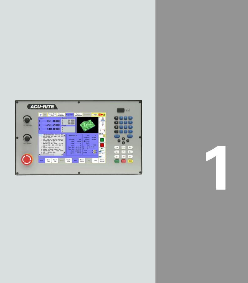
Introduction
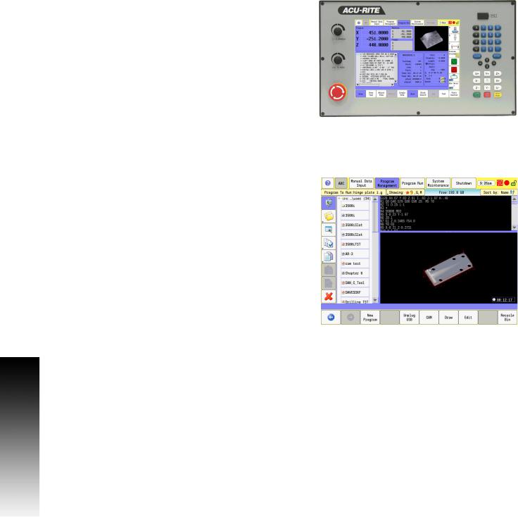
1.1 The 3500i
1.1 The 3500i
The ACU-RITE 3500i control is a touch screen workshop-oriented contouring control that enables you to program conventional machining operations right at the machine in an easy-to-use conversational programming language. The control is also capable of running, and editing g-code (ISO format) programs. It is designed for milling and drilling machine tools, as well as machining centers, with up to four axes. You can also change the angular position of the spindle under program control.
The 3500i has many powerful features that will improve your productivity. The touch screen features, and screen layout are clearly arranged in such a way that the functions are easy to access, fast and user friendly.
ACU-RITE conversational, and G-code formats
The ACU-RITE conversational programming format is a method of writing programs; g-code (ISO) programming is also supported. Preview graphics in the editors illustrate the individual machining steps for programming the contour as well as the corresponding tool path generated. If a production drawing is not dimensioned for NC programming, the CAM can be used to graphically generate a complete part program. Work piece machining can be graphically simulated either during or before actual machining.
The conversational and g-code (ISO) formats are the same as that used in previous CNC products (3000M, 5000M, 6000M and 6000i).
2 |
1 Introduction |
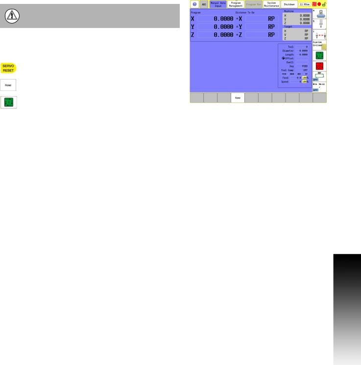
Powering Up the CNC Machine
When you power-on the CNC, ensure that the E-STOP switch is in the in position.
Turn on the CNC machine according to the builder's instructions. Turn the power switch on to the 3500i console.
The 3500i completely resets, activating the startup screen.
With the EMERGENCY STOP button out, reset the servo drive by pressing the SERVO RESET key.
Press the Home button.
Press the Start button. The 3500i default display is the Manual screen.
1.1 The 3500i
ACU-RITE 3500i |
3 |
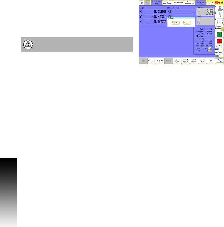
1.1 The 3500i
E-Stop, Servo Reset, and CNC Shutdown
Press E-STOP to disengage the servos and then revert to Manual Data Input Mode.
Touch Shut Down to display the Shut Down dialogue. Touch Shut Down to power down the CNC, or touch Cancel to cancel the shut down. The shutdown takes less than a minute. The 3500i will let you know when it is safe to turn power off. Or, you can touch Reboot (or press the ENTER key) to re-start the 3500i.
Follow the builder's instructions for turning off the machine.
Always shutdown the CNC before turning power off to the machine.
Emergency Stop (E-STOP)
Press E-STOP to take all axes and spindle servos offline. This ends all machine movement.
To reset E-STOP, pull out and turn the rotary switch clockwise in the direction of the arrows. The switch makes a touching sound when it resets.
Resetting E-STOP does not automatically reactivate the servos.
Activating/Resetting the Servos
For safety reasons, the CNC powers up with the servomotors disengaged. While the servos are off, the CNC cannot move the machine.
Reset the servos as follows:
If a limit switch disengaged the servos, manually reposition the machine inside its normal range of travel.
Press E-STOP to display the message External emergency stop
Rotate the E-STOP switch in the direction of the arrows to reset it.
Press SERVO RESET to reset the servos.
4 |
1 Introduction |
Loading...