


CONTENTS |
|
Unpacking Instructions............ |
2 |
Package Contents................... |
2 |
Product Registration................ |
2 |
Features & Benefits: Sensor..... |
2 |
Features & Benefits: Display.... |
3 |
Sensor Setup.......................... |
5 |
Display Setup......................... |
6 |
Setup Preferences................... |
7 |
Intelli-Time® Clock................... |
7 |
Set the Time, Date & Units....... |
7 |
Instruction Manual
Weather Station
model 02005TBDI
Placement Guidelines................. |
8 |
Using the Weather Station......... |
9 |
Troubleshooting....................... |
10 |
Care & Maintenance................ |
11 |
Replace Intelli-Time® Battery..... |
12 |
Calibration.............................. |
12 |
Specifications.......................... |
13 |
FCC Information...................... |
13 |
Customer Support.................... |
14 |
Warranty................................ |
14 |
Questions? Contact Customer Support at (877) 221-1252 or visit www.AcuRite.com.
SAVE THIS MANUAL FOR FUTURE REFERENCE.
Congratulations on your new AcuRite product. To ensure the best possible product performance, please read this manual in its entirety and retain it for future reference.
Unpacking Instructions
Remove the protective film that is applied to the LCD screen prior to using this product. Locate the tab and peel off to remove.
Package Contents
1. Display Unit
2. Outdoor Sensor
3. Instruction Manual
IMPORTANT |
TO RECEIVE WARRANTY SERVICE |
||||||||
|
|
|
|
|
|
|
|
PRODUCT MUST BE REGISTERED |
|
|
|
|
|
|
|
|
|
|
|
PRODUCT REGISTRATION |
|
|
|||||||
|
|
Register online |
|
|
|||||
|
|
to receive 1 year |
|
|
|||||
|
|
warranty protection |
|
► |
|||||
www.AcuRite.com |
|
||||||||
|
|
|
|
|
|
|
|
|
Register a Product |
Features & Benefits |
|
|
|||||||
1 |
|
|
|
|
|
|
|
OUTDOOR SENSOR |
|
|
|
|
|
|
|
|
|||
2 |
|
|
|
|
|
|
|
1. |
Integrated Hanger |
|
|
|
|
|
|
|
|
For easy placement. |
|
|
|
|
|
|
|
|
|
|
|
5 |
2. |
Wireless Signal Indicator |
|||||||
|
|
|
|
|
|
|
|
|
Flashes when data is being |
|
|
|
|
|
|
|
|
|
sent to the display unit. |
3 |
|
|
|
|
|
|
|
3. |
Battery Compartment |
|
|
|
|
|
|
|
4. |
A-B-C Switch |
|
|
|
|
|
|
|
|
|||
|
|
|
|
|
|
|
|
||
4 |
|
|
|
|
|
|
|
|
ID code that must match display’s |
|
|
|
|
|
|
|
|
A-B-C switch to ensure units |
|
|
|
|
|
|
|
|
|
|
|
|
|
|
|
|
|
|
|
|
synchronize. |
|
|
|
|
|
|
|
|
5. |
Battery Compartment Cover |
2

Features & Benefits
Display Unit Front
23 22 21 20 19 18 17 16
1 |
|
|
|
|
|
|
|
|
|
|
|
|
|
|
|
|
|
|
|
|
|
|
15 |
|
|
|
|
|
|
|
|
|
|
|
|
|
|
|
|
|
|
|
|
|
|
||
|
|
|
|
|
|
|
|
|
|
|
|
|
|
|
|
|
|
|
|
|
|||
2 |
|
|
|
|
|
|
|
|
|
|
|
|
|||||||||||
|
|
|
|
|
|
|
|
|
|
|
|
||||||||||||
|
|
||||||||||||||||||||||
3 |
|
|
|
|
|
|
|
|
|
|
|
|
|
|
|
|
|
|
|
|
|
|
|
|
|
|
|
|
|
|
|
|
|
|
|
|
|
|
|
|
|
|
|
|
|
|
|
4 |
|
|
|
|
|
|
|
|
|
|
|
|
|
|
|
|
|
|
14 |
||||
|
|
|
|
|
|
|
|
|
|
|
|
|
|
|
|
|
|
|
|
|
|
||
5 |
|
|
|
|
|
|
|
|
|
|
|
|
|
|
|
|
|
|
|
|
13 |
||
|
|
||||||||||||||||||||||
6 |
|
|
|
|
|
|
|
|
|
|
|
|
|
|
|
|
|
|
|
|
|
|
|
|
|
|
|
|
|
|
|
|
|
|
|
|
|
|
|
|
|
|
|
|
|
||
7 |
|
|
|
|
|
|
|
|
|
|
|
|
|
|
|
|
|
|
|
|
|
|
|
|
|
|
|
|
|
|
|
|
|
|
|
|
|
|
|
|
|
|
|
|
|
||
|
|
|
|
|
|
|
|
|
|
|
|
|
|
|
|
|
|
|
|
|
|
|
|
8 |
9 |
10 |
11 |
9 |
12 |
Display Unit Back
36
24
25 |
|
|
|
|
|
|
|
|
|
35 |
||
|
|
|
|
|
|
|
|
|
||||
|
|
|
|
|
|
|
|
|
|
|
34 |
|
26 |
|
|
|
|
|
|
|
|
|
|
||
|
|
|
|
|
|
|
|
|
||||
|
|
|
|
|
|
|
|
|||||
|
|
|
|
|
|
|
|
|
|
|
|
|
27 |
|
|
|
|
|
|
|
|
|
|
|
|
|
|
|
|
|
|
|
|
|
|
|
|
|
|
|
|
|
|
|
|
|
|
|
|||
28 |
|
|
|
|
|
|
|
|
|
|
|
|
|
|
|
|
|
|
|
|
|
|
|
|
|
|
|
|
|
|
|
|
|
|
|
|
|
|
|
|
|
|
|
|
|
|
|
|
|
|
|
|
|
|
|
|
|
|
|
|
|
|
|
|
29 30 31 |
32 |
33 |
|
3

DISPLAY UNIT FRONT
1.Day of the Week
2.Current Outdoor Temperature
Arrow icon indicates the direction the temperature is trending.
3.Outdoor Sensor Signal Strength
4.High/Low Outdoor Humidity Records
Highest and lowest humidity records based on record viewing mode (#9).
5.High/Low Outdoor Temperature Records
Highest and lowest temperature records based on record viewing mode (#9).
6.Forecasted High Temperature
7.Forecasted Low Temperature
8.4 Hour Weather Forecast
9.Record Viewing Mode
Indicates viewing records for today, all-time or “ “ auto-mode.
10.Outdoor Sensor Low Battery Indicator
11.4 to 8 Hour Weather Forecast
12.8 to 12 Hour Weather Forecast
13.High/Low Indoor Humidity Records
Highest and lowest humidity records based on record viewing mode (#9).
14.High/Low Indoor Temperature Records
Highest and lowest temperature records based on record viewing mode (#9).
15.Current Outdoor Humidity
Arrow icon indicates the direction the humidity is trending.
16.Date
17.Geographic Region Selection
For setup preferences.
18.Current Indoor Temperature
Arrow icon indicates the direction the temperature is trending.
19.Intelli-Time Clock®
20.Display Low Battery Icon
21.“ “ Icon
Appears while in SET mode.
22.Current Outdoor Humidity
Arrow icon indicates the direction the humidity is trending.
23.TIME ZONE & AUTO DST
DISPLAY UNIT BACK
24.”p” Button
For setup preferences.
25.“SET” Button
For setup preferences.
26.A-B-C Switch
ID code that must match sensor’s A-B-C switch to ensure units synchronize.
27.”q” Button
For setup preferences.
28.”tt” Button
Press to select record viewing mode (#9).
29.“geo” Button
Set geographical region preferences.
30.“RESET” Button
Full reset to factory defaults.
31.“zone” Button
Set time zone preferences.
32.Battery Compartment
33.Battery Compartment Cover
34.Display Kickstand
For tabletop placement.
35.Intelli-Time® Battery Compartment
36.Integrated Hang Hole
For easy wall mounting.
4
SETUP
Sensor Setup
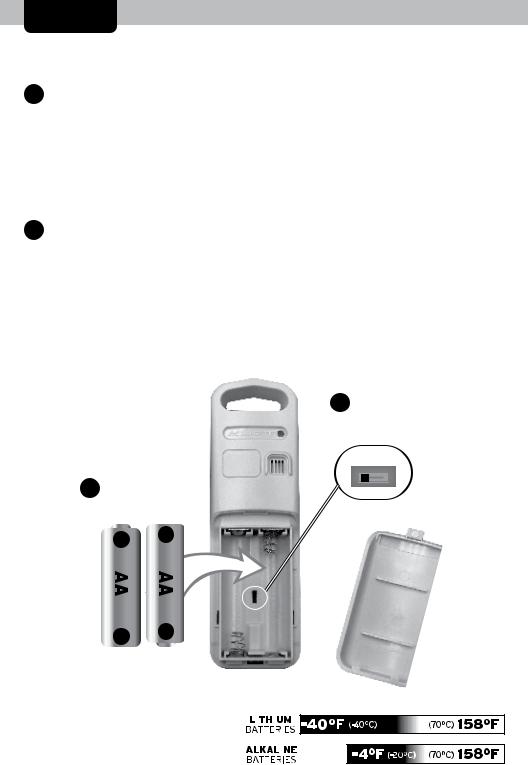
1Set the A-B-C Switch
The A-B-C switch is located inside the battery compartment. It can be set to A, B or C. However, you must select the same letter choices for both the sensor and the display unit in order for the units to synchronize.
2Install or Replace Batteries
AcuRite recommends high quality alkaline or lithium batteries in the outdoor sensor for the best
product performance. Heavy duty or rechargeable batteries are not recommended.
The sensor requires lithium
2 |
Install Batteries |
|
|
||||||||
|
2 AA batteries |
|
|
||||||||
|
|
|
|
|
|
|
|
|
|
|
|
|
|
|
|
|
|
|
|
|
|
|
|
|
|
|
|
|
|
|
|
|
|
|
|
|
|
|
|
|
|
|
|
|
|
|
|
|
|
|
|
|
|
|
|
|
|
|
|
|
|
|
|
|
|
|
|
|
|
|
|
|
|
|
|
|
|
|
|
|
|
|
|
|
|
|
|
|
|
|
|
|
|
|
|
|
|
|
|
|
|
|
|
|
|
|
|
|
|
|
|
|
|
|
|
|
|
|
|
|
|
|
|
|
|
|
|
|
|
|
|
|
|
|
|
|
|
|
|
|
|
|
|
|
|
|
|
|
|
|
|
|
|
|
|
|
|
|
|
|
|
|
|
|
|
|
|
|
|
|
|
|
|
|
|
|
|
|
|
|
|
|
|
|
|
|
|
|
|
|
|
batteries in low temperature conditions. Cold temperatures can cause alkaline batteries to function improperly. Use
lithium batteries in the sensor for temperatures below -4ºF / -20ºC.
1.Slide off the battery compartment cover. Take note of the A-B-C switch setting inside the battery compartment for display unit setup.
2.Insert 2 x AA batteries into the battery compartment, as shown. Follow the polarity (+/-) diagram in the battery compartment.
3.Replace the battery cover.
1A-B-C Switch set to match display unit
5
 Loading...