


 Loading...
Acer
Aspire M3910(G)
Service Guide
PRINTED IN TAIWAN

Revision History
Please refer to the table below for the updates made on this service guide.
Date |
Chapter |
Updates |
|
|
|
|
|
|
|
|
|
|
|
|
ii

Copyright
Copyright © 2010 by Acer Incorporated. All rights reserved. No part of this publication may be reproduced, transmitted, transcribed, stored in a retrieval system, or translated into any language or computer language, in any form or by any means, electronic, mechanical, magnetic, optical, chemical, manual or otherwise, without the prior written permission of Acer Incorporated.
iii

Disclaimer
The information in this guide is subject to change without notice.
Acer Incorporated makes no representations or warranties, either expressed or implied, with respect to the contents hereof and specifically disclaims any warranties of merchantability or fitness for any particular purpose. Any Acer Incorporated software described in this manual is sold or licensed "as is". Should the programs prove defective following their purchase, the buyer (and not Acer Incorporated, its distributor, or its dealer) assumes the entire cost of all necessary servicing, repair, and any incidental or consequential damages resulting from any defect in the software.
Acer is a registered trademark of Acer Corporation. Intel is a registered trademark of Intel Corporation.
Pentium Dual-Core, Celeron Dual-Core, Core 2 Duo, Core 2 Quad, Celeron, and combinations thereof, are trademarks of Intel Corporation.
Other brand and product names are trademarks and/or registered trademarks of their respective holders.
iv

Conventions
The following conventions are used in this manual:
SCREEN |
Denotes actual messages that appear on screen. |
MESSAGES |
|
|
|
NOTE |
Gives additional information related to the current topic. |
|
|
WARNING |
Alerts you to any physical risk or system damage that might result from doing |
|
or not doing specific actions. |
|
|
CAUTION |
Gives precautionary measures to avoid possible hardware or software |
|
problems. |
|
|
IMPORTANT |
Reminds you to do specific actions relevant to the accomplishment of |
|
procedures. |
|
|
v

Service Guide Coverage
This Service Guide provides you with all technical information relating to the BASIC CONFIGURATION decided for Acer's "global" product offering. To better fit local market requirements and enhance product competitiveness, your regional office MAY have decided to extend the functionality of a machine (e.g. add-on card, modem, or extra memory capability). These LOCALIZED FEATURES will NOT be covered in this generic service guide. In such cases, please contact your regional offices or the responsible personnel/channel to provide you with further technical details.
FRU Information
Please note WHEN ORDERING FRU PARTS, that you should check the most up-to-date information available on your regional web or channel. If, for whatever reason, a part number change is made, it will not be noted in the printed Service Guide. For ACER-AUTHORIZED SERVICE PROVIDERS, your Acer office may have a DIFFERENT part number code to those given in the FRU list of this printed Service Guide. You MUST use the list provided by your regional Acer office to order FRU parts for repair and service of customer machines.
vi

Table of Contents
System Tour |
1 |
Features |
1 |
Block Diagram |
4 |
System Components |
5 |
Front Panel |
5 |
Rear Panel |
6 |
Hardware Specifications and Configurations |
7 |
Power Management Function(ACPI support function) |
10 |
System Utilities |
11 |
CMOS Setup Utility |
11 |
Entering CMOS setup |
12 |
Navigating Through the Setup Utility |
12 |
Setup Utility Menus |
13 |
System Disassembly |
26 |
Disassembly Requirements |
26 |
Pre-disassembly Procedure |
27 |
Removing the Side Panel |
28 |
Removing the Heat Sink Fan Assembly |
29 |
Removing the Processor |
30 |
Removing the VGA Card |
31 |
Removing the TV Card |
32 |
Removing the Mode Card |
32 |
Removing the Hard Disk Drive |
33 |
Removing the Front Bezel |
35 |
Removing the Optical Drive |
36 |
Removing the Rear USB Board |
37 |
Removing the Cables |
38 |
Removing the System FAN |
39 |
Removing the Power Supply |
40 |
Removing the Memory Modules |
41 |
Removing the removable HDD bay |
42 |
Removing the Mainboard |
43 |
System Troubleshooting |
45 |
Hardware Diagnostic Procedure |
45 |
System Check Procedures |
46 |
Power System Check |
46 |
System External Inspection |
46 |
System Internal Inspection |
46 |
Beep Codes |
47 |
Checkpoints |
48 |
BIOS Recovery |
51 |
Jumper and Connector Information |
52 |
M/B Placement |
52 |
Setting Jumper |
54 |
vii

FRU (Field Replaceable Unit) List |
60 |
Aspire M3910(G) Exploded Diagram(AM350-ASSY) |
61 |
Aspire M3910(G) Exploded Diagram(AM351-ASSY) |
62 |
Aspire M3910(G) FRU List |
63 |
viii

Chapter 1
System Tour
Features
Below is a brief summary of the computer’s many feature:
NOTE: The features listed in this section is for your reference only. The exact configuration of the system depends on the model purchased.
Operating System
•Microsoft Windows 7 Home Premium 64-bits
•Microsoft Windows 7 Home Basic 64-bits
•Microsoft Windows 7 Home Premium 32-bits
•Microsoft Windows 7 Home Basic 32-bits
•Linpus X-window mode
•FreeDos
Processor
•Socket Type: Intel Socket T LGA 1156 pin
•Socket Quantity: 1
•Processor Type:
•Intel Lynnfield / Clarkdale
•FMB
•95W + 65W FMB
Chipset
•PCH: Intel H57
•Design Criteria:
•Must meet Intel Lynnfield and Clarkdale platform design guides
•Super I/O: ITE8720
•Should support Intel ASFC
•Should support Intel PECI
PCB
•uATX / 244*244mm / 4 Layers
Memory subsystem
•Socket Type: DDR III connector
•Socket Quantity: 4
•Channel A: slot 0, 1; Channel B: slot 2, 3
•Different colors for slot 0/2 and slot 1/3
•Dual channel support
•Capacity support:
•Support DDR3 1.5V 1066/1333 (1GB / 2GB / 4GB)
Chapter 1 |
1 |

•1GB to 16GB Max memory support
•Design Criteria:
•Must meet Intel Lynnfield and Clarkdale Chipset platform design guide
Hard disk
•Support up to two SATA ports
•3.5", 25.4mm
•Capacity and models are listed on AVLC
Optical disk
•Support two SATA 5.25" standard ODD
•Support DVD-ROM, DVD-SuperMulti, BD-combo, BD-rewrite
•Maximum ODD depth to 185mm with bezel
•Models are listed on AVLC
Graphics card
•No mechanical retriction to support for double slot, full length graphics cards in the single PSIe X16 slot
On-Board Graphic solution
•Intel HD Graphics (Clarkdale series CPU)
•DVMT 5.0 technology support
•Enhanced 3D and Clear Video technology support
•1 D-sub VGA port on rear
•1 HDMI port on rear
•Dual View function support
Serial ATA controller
•Slot Type: SATA connector
•Six SATA ports:
•4 for HDD
•2 for ODD
•Storage Type support:
1.HDD : Support RAID 0/1/5/10
2.CD-ROM/CD-RW/DVD-ROM/DVD-RW/DVD+RW/DVD Dual/DVD SuperMultiPlus/Blu-Ray ODD 3.AHCI mode supported for internal SATA port
Audio
•Chip : Realtek ALC662VC-0
•Connectors support:
•Rear 3 jack follow HD audio definition
•1 front panel audio header (2*5)
LAN
•MAC Controller: H57
•PHY: REALTEK RTL8111E Giga LAN(ASF suport)
2 |
Chapter 1 |
USB ports
•Ports Quantity: 12
•6 back panel ports
•On-board: 2 2*5 headers
•4 ports for front daughter board
•Connector Pin: standard Intel FPIO pin definition
•Data transfer rate support: USB 2.0/1.1
Extension slot
•Support one PCIe x 16 slot
•Support two PCIe x 1 slots
•Support one PCI slot
Total I/O ports
•1 PS/2 Keyboard port,
•1 PS/2 Mouse port
•1 D-Sub VGA port
•1 HDMI port
•1 RJ45 LAN port
•6 USB ports
•3 ports Audio jack
•One HD headphone output in front bezel
•One MIC-IN in front bezel
•4 * USB H5X2 Header (support 8 ports)
•1 * Front Audio Pannel H5X2 header
•1 * Front Panel IO H7X2 Header for Acer pin define
•1 * H1X4 CPU with SAMRT FAN controller
•1 * H1X3 System with SAMRT FAN controller
•1 * H1X4 SPDIFOUT Header for Acer pin define
•1 * H3X1 Clear CMOS Header (with jumper)
•1 * onboard Buzzer
•2 * H1X2 GPIO header
System BIOS
•16MBits / 2M Bytes
•AMI Kernel with Acer skin
Power supply
•FR 300W/nPFC 300W/PFC 250W/nPFC 250W
Chapter 1 |
3 |
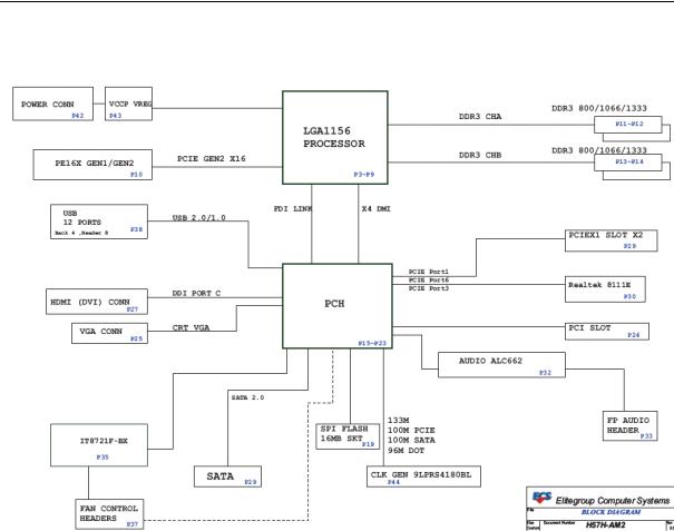
Block Diagram
|
|
|
|
|
|
|
|
4 |
Chapter 1 |
||
System Components
This section is a virtual tour of the system’s interior and exterior components.
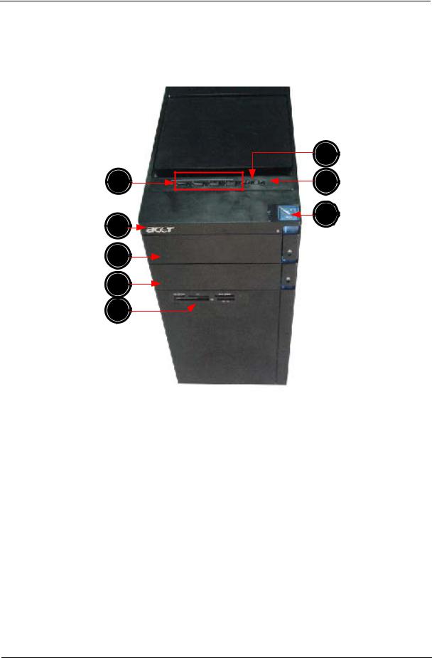
Front Panel
|
8 |
1 |
7 |
2 |
6 |
|
3
4
5
No. |
Component |
|
|
1 |
USB 2.0 ports |
2 |
Acer logo |
|
|
3 |
Optical drive button |
|
|
4 |
Optical drive button (Removable HDD bay for AM351 bezel) |
|
|
5 |
16 in 1 Card Reader |
|
|
6 |
Power button |
|
|
7 |
Headphone/Speaker-out/line-out jack |
|
|
8 |
Microphone-in jack |
|
|
Chapter 1 |
5 |

Rear Panel
1
14
2 |
13 |
|
3 |
|
|
|
12 |
|
4 |
|
|
5 |
11 |
|
10 |
||
6 |
||
9 |
||
|
||
7 |
|
|
8 |
|
No. |
Component |
|
|
1 |
Power connector |
|
|
2 |
PS2 keyboard port |
|
|
3 |
HDMI port |
|
|
4 |
VGA port |
|
|
5 |
USB 2.0 ports |
|
|
6 |
Mic-in |
|
|
7 |
Line-out |
|
|
8 |
Expansion slot (graphics card and TV tuner card and Mode card) |
|
|
9 |
Line-in |
|
|
10 |
USB 2.0 ports |
|
|
11 |
LAN connector |
|
|
12 |
System FAN |
|
|
13 |
PS2 mouse port |
|
|
14 |
Fan aperture |
|
|
6 |
Chapter 1 |

Hardware Specifications and Configurations
Processor
Item |
Specification |
|
|
Processor Type |
CPUs which complaint with Intel FSB 800/1066/1333 MHz CPUs |
|
|
Socket Type |
Intel Socket T LGA 1156 pin |
|
|
Minimum operating speed |
0 MHz (If Stop CPU Clock in Sleep State in BIOS Setup is set to Enabled.) |
|
|
BIOS
Item |
Specification |
|
|
BIOS code programer |
AMI Kernel with Acer skin |
|
|
BIOS version |
P01-A0 |
|
|
BIOS ROM type |
SPI ROM |
|
|
BIOS ROM size |
2Mb |
|
|
Support protocol |
SMBIOS(DMI)2.4/DMI2.0 |
|
|
Device Boot Support |
Support BBS spec |
|
1st priority: HDD |
|
2nd priority: CD-ROM |
|
3th priority: Removable Device |
|
4th priority: LAN |
|
|
Support to LS-120 drive |
YES |
|
|
Support to BIOS boot block feature |
YES |
|
|
IOS Hotkey List
Hotkey |
Function |
Description |
|
|
|
Del |
Enter BIOS Setup Utility |
Press while the system is booting to enter BIOS Setup Utility. |
|
|
|
Main Board Major Chips
Item |
Specification |
|
|
Chipset |
PCH: Intel H57 |
|
|
Audio controller |
Realtek ALC662VC-0 |
|
|
LAN controller |
REALTEK RTL8111E Giga LAN(ASF suport) |
|
|
HDD controller |
PCH: Intel H57 |
|
|
Chapter 1 |
7 |

Memory Combinations
Slot |
Memory |
Total Memory |
|
|
|
Slot 1 |
1GB,2GB,4G |
1G ~4GB |
|
|
|
Slot 2 |
1GB,2GB,4G |
1G ~4GB |
|
|
|
Slot 3 |
1GB,2GB,4G |
1G ~4GB |
|
|
|
Slot 4 |
1GB,2GB,4G |
1G ~4GB |
|
|
|
Maximum System Memory Supported |
1G~16GB |
|
|
|
|
System Memory
Item |
Specification |
|
|
Memory slot number |
4 slot |
|
|
Support Memory size per socket |
1GB/2GB/4GB |
|
|
Support memory type |
DDRIII |
|
|
Support memory interface |
DDRIII 1066/1333 |
|
|
Support memory voltage |
1.5V |
|
|
Support memory module package |
240-pin DDRIII |
|
|
Support to parity check feature |
Yes |
|
|
Support to error correction code (ECC) feature |
No |
|
|
Memory module combinations |
You can install memory modules in any combination as long as |
|
they match the above specifications. |
|
|
Audio Interface
Item |
Specification |
|
|
|
|
Audio controller |
PCH: Intel H57 |
|
|
|
|
Audio controller type |
Realtek ALC662VC-0 |
|
|
|
|
Audio channel |
codec 5.1 |
|
|
|
|
Audio function control |
No |
|
|
|
|
Mono or stereo |
Stereo |
|
|
|
|
Compatibility |
The ALC662VC series support host audio controller from the Intel ICH series |
|
|
chipset, and also from any other HDA compatible audio controller. With EAX/ |
|
|
Direct Sound 3D/I3DL2/A3D compatibility, and excellent software utilities like |
|
|
environment sound emulation, multiple bands of software equalizer and |
|
|
dynamic range control, optional Dolby, Digital Live, DTS CONNECT, and Dolby |
|
|
Home Theater programs, provides an excellent home entertainment package |
|
|
and game experience for PC users. |
|
|
|
|
Music synthesizer |
No |
|
|
|
|
Sampling rate |
192KHz (max) |
|
|
|
|
MPU-401 UART support |
No |
|
|
|
|
Microphone/Headphone jack |
Supported |
|
|
|
|
|
|
|
8 |
Chapter 1 |

SATA Interface
Item |
Specification |
|
|
SATA controller |
PCH: Intel H57 |
|
|
SATA controller resident bus |
PCI bus |
|
|
Number of SATA channel |
SATA X 6 |
|
|
Support bootable CD-ROM |
YES |
|
|
USB Port
Item |
Specification |
|
|
Universal HCI |
USB 2.0/1.1 |
|
|
USB Class |
Support legacy keyboard for legacy mode |
|
|
USB Connectors Quantity |
6 back real ports |
|
4 top bezel ports |
|
2 H5X2 Hedaer |
|
|
Environmental Requirements
Item |
Specification |
|
|
Temperature |
|
|
|
Operating |
+5°C ~ +35°C |
|
|
Non-operating |
-20 ~ +60°C (Storage package) |
|
|
Humidity |
|
|
|
Operating |
15% to 80% RH |
|
|
Non-operating |
10% to 90% RH |
|
|
Vibration |
|
|
|
Operating (unpacked) |
5 ~ 500 Hz: 2.20g RMS random, 10 minutes per axis in all 3 axes. |
|
5 ~500 Hz: 1.09g RMS random, 1 hour per axis in all 3 axes. |
|
|
Power Management
Devices |
S1 |
S3 |
S4 |
S5 |
|
|
|
|
|
Power Button |
V |
V |
V |
V |
|
|
|
|
|
USB Keyboard/Mouse |
V |
V |
N/A |
N/A |
|
|
|
|
|
PME |
Disabled |
Disabled |
Disabled |
Disabled |
|
|
|
|
|
RCT |
Disabled |
Disabled |
Disabled |
Disabled |
|
|
|
|
|
WOR |
Disabled |
Disabled |
Disabled |
Disabled |
|
|
|
|
|
•Devices wake up from S3 should be less than.
•Devices wake up from S5 should be less than 10 seconds.
Chapter 1 |
9 |

Power Management Function(ACPI support function)
Device Standby Mode
•Independent power management timer for hard disk drive devices(0-15 minutes,time step=1minute).
•Hard Disk drive goes into Standby mode(for ATA standard interface).
•Disable V-sync to control the VESA DPMS monitor.
•Resume method:device activated (keyboard for DOS, keyboard &mouse for Windows.
•Resume recovery time 3-5sec
Global Standby Mode
•Global power management timer(2-120minutes,time step=10minute).
•Hard disk drive goes into Standby mode(for ATA standard interface).
•Disable H-sync and V-sync signals to control the VESA DPMS monitor.
•Resume method: Resume to original state by pushing external switch Button,modem ring in,keyboard an mouse for APM mode.
•Resume recovery time :7-10sec
Suspend Mode
•Independent power management timer(2-120minutes,time step=10minute)or pushing extern switch button.
•CPU goes into SMM
•CPU asserts STPCLK# and goes into the Stop Grant State.
•LED on panel turns amber colour.
•Hard disk drive goes into SLEEP mode (for ATA standard interface).
•Disable H-sync and V-sync signals to control the VESA DPMS monitor.
•Ultra I/O and VGA chip go into power saving mode.
•Resume method: Resume to original state by pushing external switch Button,modem ring in,keyboard an mouse for APM mode
•Return to original state by pushing external switch button,modem ring in and USB keyboard for ACPI mode.
ACPI
•ACPI specification 1.0b
•S0,S1,S2 and S5 sleep state support.
•On board device power management support.
•On board device configuration support.
10 |
Chapter 1 |

Chapter 2
System Utilities
CMOS Setup Utility
CMOS setup is a hardware configuration program built into the system ROM, called the complementary metaloxide semiconductor (CMOS) Setup Utility. Since most systems are already properly configured and optimized, there is no need to run this utility. You will need to run this utility under the following conditions.
•When changing the system configuration settings
•When redefining the communication ports to prevent any conflicts
•When modifying the power management configuration
•When changing the password or making other changes to the security setup
•When a configuration error is detected by the system and you are prompted ("Run Setup" message) to make changes to the CMOS setup
NOTE: If you repeatedly receive Run Setup messages, the battery may be bad. In this case, the system cannot retain configuration values in CMOS. Ask a qualified technician for assistance.
CMOS setup loads the configuration values in a battery-backed nonvolatile memory called CMOS RAM. This memory area is not part of the system RAM which allows configuration data to be retained when power is turned off.
Before you run the CMOS Setup Utility, make sure that you have saved all open files. The system reboots immediately after you close the Setup.
NOTE: CMOS Setup Utility will be simply referred to as “BIOS”, "Setup", or "Setup utility" in this guide.
The screenshots used in this guide display default system values. These values may not be the same those found in your system.
Chapter 2 |
11 |

Entering CMOS setup
1.Turn on the server and the monitor.
If the server is already turned on, close all open applications, then restart the server.
2.During POST, press Delete.
If you fail to press Delete before POST is completed, you will need to restart the server.
The Setup Main menu will be displayed showing the Setup’s menu bar. Use the left and right arrow keys to move between selections on the menu bar.
Navigating Through the Setup Utility
Use the following keys to move around the Setup utility.
•Left and Right arrow keys – Move between selections on the menu bar.
•Up and Down arrow keys – Move the cursor to the field you want.
•PgUp and PgDn keys – Move the cursor to the previous and next page of a multiple page menu.
•Home – Move the cursor to the first page of a multiple page menu.
•End – Move the cursor to the last page of a multiple page menu.
•+ and - keys – Select a value for the currently selected field (only if it is user-configurable). Press these keys repeatedly to display each possible entry, or the Enter key to choose from a pop-up menu.
NOTE: Grayed-out fields are not user-configurable.
•Enter key – Display a submenu screen. NOTE: Availability of submenu screen is indicated by a (>).
•Esc – If you press this key:
•On one of the primary menu screens, the Exit menu displays.
•On a submenu screen, the previous screen displays.
•When you are making selections from a pop-up menu, closes the pop-up without making a selection.
•F1 – Display the General Help panel.
•F6 – Press to load optimized default system values.
•F7 – Press to load fail-safe default system values.
•F10 – Save changes made the Setup and close the utility.
12 |
Chapter 2 |
Setup Utility Menus
The Setup Main menu includes the following main setup categories.
Parameter |
Description |
|
|
Product Information |
This page shows the relevant information of the main board |
|
|
Standard CMOS Features |
This setup page includes all the items in standard compatible BIOS |
|
|
Advanced BIOS Features |
This setup page includes all the items of Award special enhanced features |
|
|
Advanced Chipset Features |
This setup page includes all advanced chipset features |
|
|
Integrated Peripherals |
This setup page includes all onboard peripherals |
|
|
Power Management Setup |
This setup page includes all the items of Green function features |
|
|
PC Health Status |
This setup page is the System auto detect Temperature, voltage, and fan speed |
|
|
Frequency/Voltage Control |
This setup page is the System Frequency setup |
|
|
BIOS Security Features |
Change, set or disable password. It allows you to limit access to the System |
|
|
Load Default Setting |
Load Default Setting indicates the value of the system parameters which the system would be |
|
in best performance configuration |
|
|
Save & Exit Setup |
Save CMOS value settings to CMOS and exit setup |
|
|
Exit Without Saving |
Abandon all CMOS value changes and exit setup |
|
|
In the descriptive table following each of the menu screenshots, settings in boldface are the default and suggested settings.
Chapter 2 |
13 |
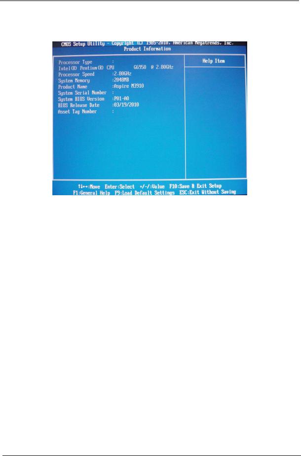
Product Information
The Product Information menu displays basic information about the system. These entries are for your reference only and are not user-configurable.
Parameter |
Description |
|
|
Processor Type |
Type of CPU installed on the system. |
|
|
Processor Speed |
Speed of the CPU installed on the system. |
|
|
System Memory |
Total size of system memory installed on the system. |
|
|
Product Name |
Product name of the system. |
|
|
System Serial Number |
Serial number of the system. |
|
|
System BIOS Version |
Version number of the BIOS setup utility. |
|
|
BIOS Release Date |
Date when the BIOS setup utility was released |
|
|
Asset Tag Number |
Asset tag number of this system. |
|
|
14 |
Chapter 2 |
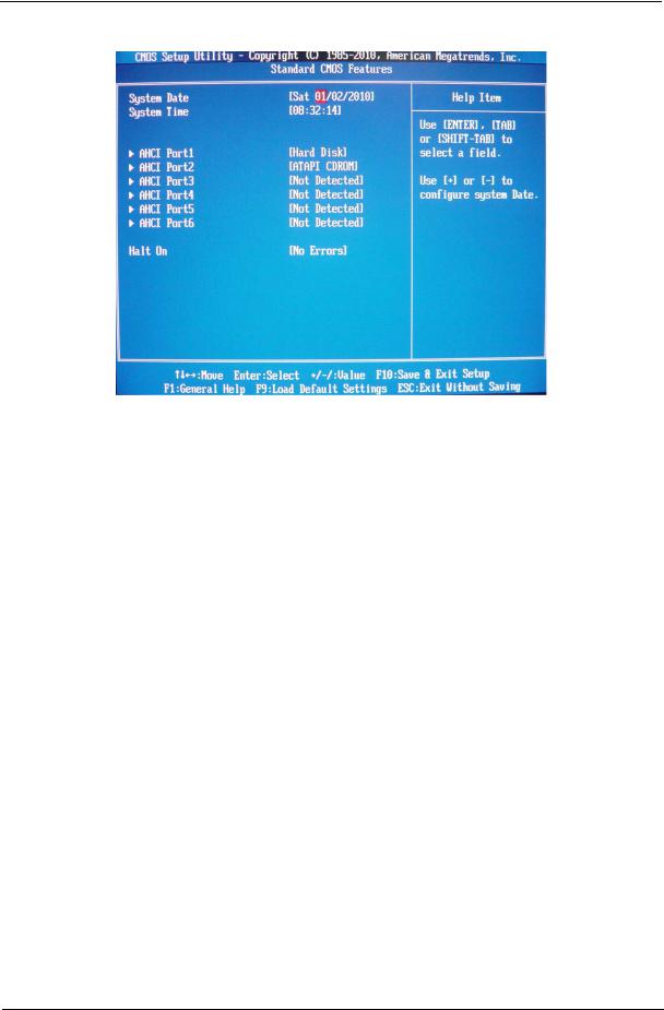
Standard CMOS Features
Parameter |
Description |
Option |
|
|
|
System Date |
Set the date following the weekday-month-day-year format. |
|
|
|
|
System Time |
Set the system time following the hour-minute-second format. |
|
|
|
|
Halt On |
Determines whether the system will stop for an error during the POST. |
All, But Keyboard |
|
|
No Errors |
|
|
All Errors |
|
|
|
Chapter 2 |
15 |
Loading...