


 Loading...
Acer
Aspire M3920
Service Guide

Revision History
Please refer to the table below for the updates made on this service guide.
Date |
Chapter |
Updates |
|
|
|
|
|
|
|
|
|
|
|
|
ii

Copyright
Copyright © 2010 by Acer Incorporated. All rights reserved. No part of this publication may be reproduced, transmitted, transcribed, stored in a retrieval system, or translated into any language or computer language, in any form or by any means, electronic, mechanical, magnetic, optical, chemical, manual or otherwise, without the prior written permission of Acer Incorporated.
iii

Disclaimer
The information in this guide is subject to change without notice.
Acer Incorporated makes no representations or warranties, either expressed or implied, with respect to the contents hereof and specifically disclaims any warranties of merchantability or fitness for any particular purpose. Any Acer Incorporated software described in this manual is sold or licensed "as is". Should the programs prove defective following their purchase, the buyer (and not Acer Incorporated, its distributor, or its dealer) assumes the entire cost of all necessary servicing, repair, and any incidental or consequential damages resulting from any defect in the software.
Acer is a registered trademark of Acer Corporation. Intel is a registered trademark of Intel Corporation.
Pentium Dual-Core, Celeron Dual-Core, Core 2 Duo, Core 2 Quad, Celeron, and combinations thereof, are trademarks of Intel Corporation.
Other brand and product names are trademarks and/or registered trademarks of their respective holders.
iv

Conventions
The following conventions are used in this manual:
SCREEN |
Denotes actual messages that appear on screen. |
MESSAGES |
|
|
|
NOTE |
Gives additional information related to the current topic. |
|
|
WARNING |
Alerts you to any physical risk or system damage that might result from doing |
|
or not doing specific actions. |
|
|
CAUTION |
Gives precautionary measures to avoid possible hardware or software |
|
problems. |
|
|
IMPORTANT |
Reminds you to do specific actions relevant to the accomplishment of |
|
procedures. |
|
|
v

Service Guide Coverage
This Service Guide provides you with all technical information relating to the BASIC CONFIGURATION decided for Acer's "global" product offering. To better fit local market requirements and enhance product competitiveness, your regional office MAY have decided to extend the functionality of a machine (e.g. add-on card, modem, or extra memory capability). These LOCALIZED FEATURES will NOT be covered in this generic service guide. In such cases, please contact your regional offices or the responsible personnel/channel to provide you with further technical details.
FRU Information
Please note WHEN ORDERING FRU PARTS, that you should check the most up-to-date information available on your regional web or channel. If, for whatever reason, a part number change is made, it will not be noted in the printed Service Guide. For ACER-AUTHORIZED SERVICE PROVIDERS, your Acer office may have a DIFFERENT part number code to those given in the FRU list of this printed Service Guide. You MUST use the list provided by your regional Acer office to order FRU parts for repair and service of customer machines.
vi

|
Table of Contents |
Features and Specifications ................................................................... |
1 |
System Features . . . . . . . . . . . . . . . . . . . . . . . . . . . . . . . . . . |
. . . . . . . . . . . . . . . . . . . .1 |
Audio . . . . . . . . . . . . . . . . . . . . . . . . . . . . . . . . . . . . . . . . . . . |
. . . . . . . . . . . . . . . . . . . .2 |
I/O Ports and LED Indicators . . . . . . . . . . . . . . . . . . . . . . . . . . |
. . . . . . . . . . . . . . . . . . . .2 |
Physical Specifications . . . . . . . . . . . . . . . . . . . . . . . . . . . . . . |
. . . . . . . . . . . . . . . . . . . .3 |
Environmental Requirements . . . . . . . . . . . . . . . . . . . . . . . . . |
. . . . . . . . . . . . . . . . . . . .3 |
Power Management Function(ACPI support function) . . . . . . |
. . . . . . . . . . . . . . . . . . . .3 |
System Tour . . . . . . . . . . . . . . . . . . . . . . . . . . . . . . . . . . . . . . |
. . . . . . . . . . . . . . . . . . . 4 |
Front View . . . . . . . . . . . . . . . . . . . . . . . . . . . . . . . . . . . |
. . . . . . . . . . . . . . . . . . . 4 |
Rear View . . . . . . . . . . . . . . . . . . . . . . . . . . . . . . . . . . . . |
. . . . . . . . . . . . . . . . . . . 5 |
System Utilities ....................................................................................... |
7 |
CMOS Setup Utility . . . . . . . . . . . . . . . . . . . . . . . . . . . . . . . |
. . . . . . . . . . . . . . . . . . . 7 |
Entering CMOS setup . . . . . . . . . . . . . . . . . . . . . . . . . . |
. . . . . . . . . . . . . . . . . . . 8 |
Navigating Through the Setup Utility . . . . . . . . . . . . . . . |
. . . . . . . . . . . . . . . . . . . .8 |
Setup Utility Menus . . . . . . . . . . . . . . . . . . . . . . . . . . . . |
. . . . . . . . . . . . . . . . . . . .9 |
System Disassembly ............................................................................. |
21 |
Disassembly Requirements . . . . . . . . . . . . . . . . . . . . . . . . . . . |
. . . . . . . . . . . . . . . . . . .21 |
Pre-disassembly Procedure . . . . . . . . . . . . . . . . . . . . . . . . . . |
. . . . . . . . . . . . . . . . . . .21 |
Removing the Side Panel . . . . . . . . . . . . . . . . . . . . . . . . . |
. . . . . . . . . . . . . . . . . . 22 |
Removing the Heatsink Fan Assembly . . . . . . . . . . . . . . . |
. . . . . . . . . . . . . . . . . . .23 |
Removing the Processor . . . . . . . . . . . . . . . . . . . . . . . . . |
. . . . . . . . . . . . . . . . . . .24 |
Removing the VGA Card . . . . . . . . . . . . . . . . . . . . . . . . |
. . . . . . . . . . . . . . . . . . .26 |
Removing the Mode Card . . . . . . . . . . . . . . . . . . . . . . . |
. . . . . . . . . . . . . . . . . . .27 |
Removing the TV Card . . . . . . . . . . . . . . . . . . . . . . . . . . |
. . . . . . . . . . . . . . . . . . .28 |
Removing the Memory Modules . . . . . . . . . . . . . . . . . . . |
. . . . . . . . . . . . . . . . . . 28 |
Removing the Hard Disk Drive . . . . . . . . . . . . . . . . . . . . . |
. . . . . . . . . . . . . . . . . . 29 |
Removing the USB Board . . . . . . . . . . . . . . . . . . . . . . . . |
. . . . . . . . . . . . . . . . . . .32 |
Removing the Front Bezel . . . . . . . . . . . . . . . . . . . . . . . . |
. . . . . . . . . . . . . . . . . . .35 |
Removing the Optical Drive . . . . . . . . . . . . . . . . . . . . . . . |
. . . . . . . . . . . . . . . . . . 37 |
Removing the Removable HDD . . . . . . . . . . . . . . . . . . . . |
. . . . . . . . . . . . . . . . . . 39 |
Removing the Card Reader . . . . . . . . . . . . . . . . . . . . . . . |
. . . . . . . . . . . . . . . . . . .43 |
Removing the Power Supply . . . . . . . . . . . . . . . . . . . . . . |
. . . . . . . . . . . . . . . . . . .46 |
Removing the Mainboard . . . . . . . . . . . . . . . . . . . . . . . |
. . . . . . . . . . . . . . . . . . .48 |
System Troubleshooting ...................................................................... |
51 |
Hardware Diagnostic Procedure . . . . . . . . . . . . . . . . . . . . . . . . . . . . . . . . . . . . . .51 System Check Procedures . . . . . . . . . . . . . . . . . . . . . . . . . . . . . . . . . . . . . . . . . . .52 Power System Check . . . . . . . . . . . . . . . . . . . . . . . . . . . . . . . . . . . . . . . . . . . . . .52 System External Inspection . . . . . . . . . . . . . . . . . . . . . . . . . . . . . . . . . . . . . . . . . 52 System Internal Inspection . . . . . . . . . . . . . . . . . . . . . . . . . . . . . . . . . . . . . . . . . .52 Beep Codes . . . . . . . . . . . . . . . . . . . . . . . . . . . . . . . . . . . . . . . . . . . . . . . . . . . . .53 Checkpoints . . . . . . . . . . . . . . . . . . . . . . . . . . . . . . . . . . . . . . . . . . . . . . . . . . . . .54 Viewing BIOS checkpoints . . . . . . . . . . . . . . . . . . . . . . . . . . . . . . . . . . . . . . . . . .54 Bootblock Initialization Code Checkpoints . . . . . . . . . . . . . . . . . . . . . . . . . . . . . .54 Bootblock Recovery Code Checkpoints . . . . . . . . . . . . . . . . . . . . . . . . . . . . . . . . .56 BIOS Recovery . . . . . . . . . . . . . . . . . . . . . . . . . . . . . . . . . . . . . . . . . . . . . . . . . . .57
System Architecture ............................................................................. |
59 |
Block Diagram . . . . . . . . . . . . . . . . . . . . . . . . . . . . . . . . . . . . . . . . . . . . . . . . . . . . . . .59
Mainboard Layout . . . . . . . . . . . . . . . . . . . . . . . . . . . . . . . . . . . . . . . . . . . . . . . .60
Jumper Setting . . . . . . . . . . . . . . . . . . . . . . . . . . . . . . . . . . . . . . . . . . . . . . . . . . .61
vii

Table of Contents
Jumper Setting . . . . . . . . . . . . . . . . . . . . . . . . . . . . . . . . . . . . . . . . . . . . . . . . . . .61
Connecting Optional Devices . . . . . . . . . . . . . . . . . . . . . . . . . . . . . . . . . . . . . . . .65
Connecting Case Components . . . . . . . . . . . . . . . . . . . . . . . . . . . . . . . . . . . . . . .67
FRU (Field Replaceable Unit) List ......................................................... |
69 |
|
Aspire M3920 |
Exploded Diagram . . . . . . . . . . . . . . . . . . . . . . . . . . . . . . . . . . . . . . . . |
.70 |
Aspire M3920 |
FRU List . . . . . . . . . . . . . . . . . . . . . . . . . . . . . . . . . . . . . . . . . . . . . . |
.71 |
viii

Chapter 1
Features and Specifications
This chapter lists the features and specifications of this computer.
NOTE The items listed in this section are for reference only. The exact configuration of your PC depends on the model purchased. Refer to the FRU list chapter on page 69 for a detailed list of models supported by each hardware component.
System Features
Component |
Description |
|
|
|
|
Operating system support |
• |
Microsoft Windows 7 Home Premium (X64/X86) |
|
• |
Microsoft Windows 7 Home Basic (X64/X86) |
|
• Microsoft Windows 7 Starter X86 |
|
|
• Linpus Linux x-Window mode |
|
|
• |
Free Dos |
|
|
|
Processor |
• |
LGA-1155 socket |
|
• Supports the following Intel processors: |
|
|
|
– Core i7 2600 3.4G 8M 1333 95W D-2 |
|
|
– Core i5 2500 6M 1333 95W D-2 3.3G |
|
|
– Core i5 2400 6M 1333 95W D-2, quad core |
|
|
– Core i5 2300 2.8G 6M 1333 95W D-2 |
|
|
– Core i3-2120 3.3GHz 2C/4T 3MB |
|
|
– Core i3-2100 3.1GHz 2C/4T 3MB |
|
|
|
Chipset |
• |
PCH: Intel H67 |
|
|
|
Graphics |
• |
Intel® HD Graphics Support (supported by CPU) |
|
|
– Dual independent display |
|
|
– Digital display (HDMI/DVI/DP/eDP) and VGA |
|
• DVMT 5.0 technology support |
|
|
• Enhanced 3D and Clear Video technology support |
|
|
|
|
Memory |
• |
Four DIMM sockets (two channels, two slots per channel) |
|
• |
Dual channel support |
|
|
– Channel A: slot 0, 1; Channel B: slot 2, 3 |
|
|
– Different colors for slot 0/2 and slot 1/3 |
|
• Supports 1GB, 2 GB and 4GB DDR III Unbuffered Non-ECC DIMM |
|
|
|
modules |
|
• Data rates supported: 800/1066/1333 MT/s |
|
|
• Maximum memory: 16 GB (using 4 GB modules) |
|
|
|
|
Expansion options |
• |
One PCIE x16 (PCIE V2.0) slot |
|
• Three PCIE x1 (PCIE V2.0) slots |
|
|
|
|
Connectivity |
• |
Wired LAN: GigaLAN |
|
• WLAN option: 802.11 b/g/n wireless network adapter |
|
|
|
|
Hard disk drive (HDD) |
• |
Supports up to three 3.5-inch 25.4 mm SATA HDDs |
|
• Capacity and models are listed in FRU list |
|
|
|
|
Optical disc drive (ODD) |
• |
Suports up to two 5.25-inch standard SATA ODDs |
|
• Supports DVD-ROM, DVD-SuperMulti, BD-combo, BD-rewrite |
|
|
• Models are listed in FRU list |
|
|
|
|
Chapter 1 |
1 |

Component |
Description |
|
|
|
|
Card reader (optional) |
• 16-in-1 card reader (optional) |
|
|
• The following memory cards are supported: |
|
|
– |
Memory Stick (MS),Memory Stick Pro, Memory Stick Micro (M2) |
|
– |
xD-Picture Card (xD) |
|
– |
Secure Digital (SD), MultiMediaCard (MMC) |
|
– |
CompactFlash, Type I/II (CF, Type I and II) |
|
– Memory Stick PRO (MS PRO) |
|
|
|
|
TV tuner (optional) |
• Avermedia H753-A TV Tuner Card PCIe Hybrid ATSC card |
|
|
• Avermedia H753-D TV Tuner Card PCIe Hybrid DVB-T card |
|
|
• Avermedia H753-C TV Tuner Card PCIe Hybrid DMB-TH card |
|
|
|
|
Power supply |
• 300 W power supply unit (non-PFC, non-power factor correction), |
|
|
100-127V/220-240V (4SATA1PATA) co-module |
|
|
• 300 W power supply unit (PFC), 100-127v/220v-240V |
|
|
(4SATA1PATA) co-module |
|
|
|
|
Antivirus software |
Norton Internet Security |
|
|
|
|
System BIOS |
• AMI Kernel with Acer skin |
|
|
• Supports ACPI revision 2.0 standard |
|
|
• Supports Plug and Play, STR(S3)/STD(S4), hardware monitor, Multi Boot, |
|
|
and DMI protocols |
|
|
|
|
Power management |
• ACPI 2.0 or 1.0b (Advanced Configuration Power Interface) standard |
|
|
• S0, S1, S2 and S5 sleep states support |
|
|
• On-board device power management support |
|
|
• On-board device configuration support |
|
|
|
|
Audio
Item |
Description |
|
|
|
|
Audio codec |
• Realtek ALC662 5.1 Channel High Definition Audio Codec |
|
|
|
|
Audio jacks |
• |
Front panel: Headphone and microphone jacks |
|
• |
Rear panel: Microphone, line-out, and line-in jacks |
|
|
|
I/O Ports and LED Indicators
Component |
Description |
||
|
|
|
|
I/O ports |
• |
Front panel |
|
|
|
– Four USB ports |
|
|
|
– One headphone jack |
|
|
|
– One microphone jack |
|
|
|
– |
16-in-1 card reader |
|
• |
Rear panel |
|
|
|
– One PS/2 keyboard |
|
|
|
– One PS/2 mouse port |
|
|
|
– |
External display (VGA) port |
|
|
– One HDMI port |
|
|
|
– |
Eight USB ports |
|
|
– |
One Ethernet jack (RJ45) |
|
|
– |
Microphone, line-out, and line-in jacks |
|
|
|
|
LED indicators |
• |
Hard drive activity |
|
|
• |
Power status |
|
|
|
|
|
2 |
Chapter 1 |
Physical Specifications
Aspect |
Description |
|
|
Chassis dimension (W × D × H) |
180 mm (W) x 401.8 mm (D) x 379 mm (H) |
|
|
System weight |
8.168 kg. |
|
|
Mainboard form factor |
MicroATX (µATX) |
|
|
Mainboard dimensions (W × H) |
244 mm x 244 mm |
|
|
Environmental Requirements
Aspect |
Description |
|
|
Operating temperature |
5 to 35 °C (41 to 95 °F) |
|
|
Operating humidity |
15% to 80% RH non-condensing |
|
|
Power Management Function(ACPI support function)
Device Standby Mode
•Independent power management timer for hard disk drive devices (0-15 minutes,time step=1minute).
•Hard Disk drive goes into Standby mode(for ATA standard interface).
•Disable V-sync to control the VESA DPMS monitor.
•Resume method:device activated (keyboard for DOS, keyboard &mouse for Windows.
•Resume recovery time 3-5sec
Global Standby Mode
•Global power management timer (2-120minutes,time step=10minute).
•Hard disk drive goes into Standby mode(for ATA standard interface).
•Disable H-sync and V-sync signals to control the VESA DPMS monitor.
•Resume method: Resume to original state by pushing external switch Button,modem ring in,keyboard an mouse for APM mode.
•Resume recovery time :7-10sec
Suspend Mode
•Independent power management timer(2-120minutes,time step=10minute)or pushing extern switch button.
•CPU goes into SMM
•CPU asserts STPCLK# and goes into the Stop Grant State.
•LED on panel turns amber colour.
•Hard disk drive goes into SLEEP mode (for ATA standard interface).
•Disable H-sync and V-sync signals to control the VESA DPMS monitor.
•Ultra I/O and VGA chip go into power saving mode.
•Resume method: Resume to original state by pushing external switch Button,modem ring in,keyboard an mouse for APM mode
•Return to original state by pushing external switch button,modem ring in and USB keyboard for ACPI mode.
Chapter 1 |
3 |
System Tour
The pictures and tables in this section illustrate the physical outlook of the computer.
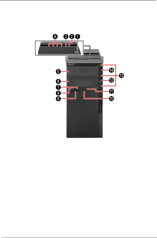
Front View
No. |
Component |
|
|
1 |
Power button |
|
|
2 |
Headphone/Speaker-out/line-out jack |
|
|
3 |
Microphone-in jack |
|
|
4 |
USB 2.0 ports |
|
|
5 |
Master optical drive bay door |
|
|
6 |
Slave bay door (optical drive bay, removable HDD bay) |
|
|
7 |
XD slot |
|
|
8 |
Memory Stick / Micro Secure Digital |
|
|
9 |
CF I/II (CompactFlash Type I/II) slot |
|
|
10 |
Memory Stick / Memory Stick Pro. |
|
|
11 |
Secure Digital / Multi media card |
|
|
12 |
Master optical drive button |
|
|
13 |
Cosmetic LED |
|
|
14 |
Slave optical drive button |
|
|
4 |
Chapter 1 |
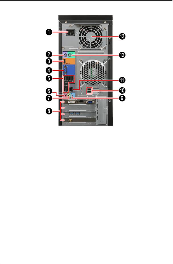
Rear View
No. |
Component |
|
|
1 |
Power connector |
2 |
PS2 keyboard port |
|
|
4 |
VGA port |
|
|
3 |
HDMI port |
|
|
5 |
USB 2.0 ports |
|
|
6 |
Microphone |
|
|
7 |
Line-out jack |
|
|
8 |
Expansion slot (graphics card and TV tuner card and Mode card) |
|
|
9 |
Line-in jack |
|
|
10 |
USB 2.0 ports |
|
|
11 |
RJ45 LAN connector |
|
|
12 |
PS2 mouse port |
|
|
13 |
System fan |
|
|
Chapter 1 |
5 |

6 |
Chapter 1 |

Chapter 2
System Utilities
CMOS Setup Utility
CMOS setup is a hardware configuration program built into the system ROM, called the complementary metaloxide semiconductor (CMOS) Setup Utility. Since most systems are already properly configured and optimized, there is no need to run this utility. You will need to run this utility under the following conditions.
•When changing the system configuration settings
•When redefining the communication ports to prevent any conflicts
•When modifying the power management configuration
•When changing the password or making other changes to the security setup
•When a configuration error is detected by the system and you are prompted ("Run Setup" message) to make changes to the CMOS setup
NOTE: If you repeatedly receive Run Setup messages, the battery may be bad. In this case, the system cannot retain configuration values in CMOS. Ask a qualified technician for assistance.
CMOS setup loads the configuration values in a battery-backed nonvolatile memory called CMOS RAM. This memory area is not part of the system RAM which allows configuration data to be retained when power is turned off.
Before you run the CMOS Setup Utility, make sure that you have saved all open files. The system reboots immediately after you close the Setup.
NOTE: CMOS Setup Utility will be simply referred to as “BIOS”, "Setup", or "Setup utility" in this guide.
The screenshots used in this guide display default system values. These values may not be the same those found in your system.
Chapter 2 |
7 |

Entering CMOS setup
1.Turn on the computer and the monitor.
If the computer is already turned on, close all open applications, then restart the computer.
2.During POST, press Delete.
If you fail to press Delete before POST is completed, you will need to restart the computer.
The Setup Main menu will be displayed showing the Setup’s menu bar. Use the left and right arrow keys to move between selections on the menu bar.
Navigating Through the Setup Utility
Use the following keys to move around the Setup utility.
•Left and Right arrow keys – Move between selections on the menu bar.
•Up and Down arrow keys – Move the cursor to the field you want.
•+ and - keys – Select a value for the currently selected field (only if it is user-configurable). Press these keys repeatedly to display each possible entry, or the Enter key to choose from a pop-up menu.
NOTE: Grayed-out fields are not user-configurable.
•Enter key – Display a submenu screen. NOTE: Availability of submenu screen is indicated by a (>).
•Esc – If you press this key:
•On one of the primary menu screens, the Exit menu displays.
•On a submenu screen, the previous screen displays.
•When you are making selections from a pop-up menu, closes the pop-up without making a selection.
•F1 – Display the General Help panel.
•F7 – Press to load user default values.
•F8 – Press to save user default values.
•F9 – Press to load optimized default system values.
•F10 – Save changes made the Setup and close the utility.
8 |
Chapter 2 |

Setup Utility Menus
The Setup Main menu includes the following main setup categories.
•Main
•Advanced
•Power
•Security
•Boot Options
•Exit
In the descriptive table following each of the menu screenshots, settings in boldface are the default and suggested settings.
Chapter 2 |
9 |
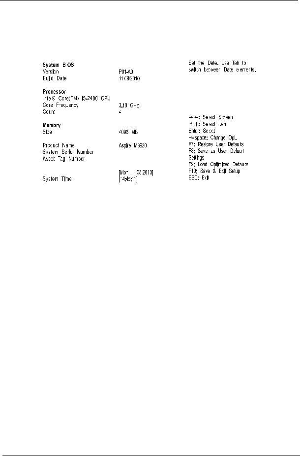
Main
The Main menu displays basic information about the system.
|
|
|
|
|
|
|
|
|
|
|
|
|
|
|
|
|
|
|
|
|
|
|
|
|
|
|
|
|
|
|
|
|
|
|
|
|
|
|
|
|
|
|
|
|
|
|
|
|
|
|
|
|
|
|
|
|
|
|
|
|
|
|
|
|
|
|
|
|
|
|
|
|
|
|
|
|
|
|
|
|
|
|
|
|
|
|
|
|
|
|
|
|
|
|
|
|
|
|
|
|
|
|
|
|
|
|
|
|
|
|
|
|
|
|
|
|
|
|
|
|
|
|
|
|
|
|
|
|
|
|
|
|
|
|
|
|
|
|
|
|
|
|
|
|
|
|
|
|
|
|
|
|
|
|
|
|
|
|
|
|
|
|
|
|
|
|
|
|
|
|
|
|
|
|
|
|
|
|
|
|
|
|
|
|
|
|
|
|
|
|
|
|
|
|
|
|
|
|
|
|
|
|
|
|
|
|
|
|
|
|
|
|
|
|
|
|
|
|
|
|
|
|
|
|
|
|
|
|
|
|
|
|
|
|
|
|
|
|
|
|
|
|
|
|
|
|
|
|
|
|
|
|
|
|
|
|
|
|
|
|
|
|
|
|
|
|
|
|
|
|
|
|
|
|
|
|
|
|
|
|
|
|
|
|
|
|
|
|
|
|
|
|
|
|
|
|
|
|
|
|
|
|
|
|
|
|
|
|
|
|
|
|
|
|
|
|
|
|
|
|
|
|
|
|
|
|
|
|
|
|
|
|
|
|
|
|
|
|
|
|
|
|
|
|
|
|
|
|
|
Parameter |
Description |
||||||||||||
|
|
|
|
|
|
|
|
|
|
|
|
|
|
System BIOS |
|
|
|
|
|
|
|
||||||
|
|
|
|
|
|
|
|
|
|
|
|
|
|
Version |
Version number of the BIOS setup utility. |
||||||||||||
|
|
|
|
|
|
|
|
|
|
|
|
|
|
Build Date |
Date when the BIOS setup utility was built. |
||||||||||||
|
|
|
|
|
|
|
|
|
|
|
|
|
|
Processor |
Type of CPU installed on the system. |
||||||||||||
|
|
|
|
|
|
|
|
|
|
|
|
|
|
Core Frequency |
Core speed of the CPU installed on the system. |
||||||||||||
|
|
|
|
|
|
|
|
|
|
|
|
|
|
Count |
Physical CPU count |
||||||||||||
|
|
|
|
|
|
|
|
|
|
|
|
|
|
Memory |
|
|
|
|
|
|
|
||||||
|
|
|
|
|
|
|
|
|
|
|
|
|
|
Size |
Total size of system memory installed on the system. |
||||||||||||
|
|
|
|
|
|
|
|
|
|
|
|
|
|
Product Name |
Product name of the system. |
||||||||||||
|
|
|
|
|
|
|
|
|
|
|
|
|
|
System Serial Number |
Serial number of the system. |
||||||||||||
|
|
|
|
|
|
|
|
|
|
|
|
|
|
Asset Tag Number |
Asset tag number of this system. |
||||||||||||
|
|
|
|
|
|
|
|
|
|
|
|
|
|
System Date |
Set the date following the weekday-month-day-year format. |
||||||||||||
|
|
|
|
|
|
|
|
|
|
|
|
|
|
System Time (hh:mm:ss) |
Set the system time following the hour-minute-second format. |
||||||||||||
|
|
|
|
|
|
|
|
|
|
|
|
|
|
10 |
Chapter 2 |
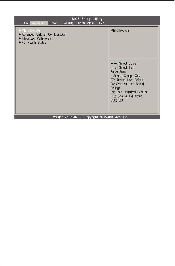
Advanced |
Parameter |
Description |
|
|
Miscellaneous |
Press Enter to access the Miscellaneous submenu |
|
|
Advanced Chipset Configuration |
Press Enter to access the Advanced Chipset Configuration submenu |
|
|
Integrated Peripherals |
Press Enter to access the Integrated Peripherals submenu |
|
|
PC Health Status |
Press Enter to access the PC Health Status submenu |
|
|
Chapter 2 |
11 |
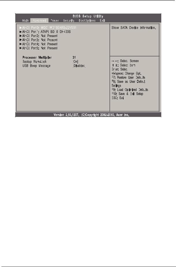
Miscellaneous |
Parameter |
Description |
Option |
|
|
|
AHCI Port0/1/2/3/4/5 |
Displays the status of auto detection of the AHCI device. |
|
|
|
|
Processor Multiplier |
This field is only visible if an engineering processor installed. It is only |
|
|
accessible when the EIST function is disabled. |
|
|
|
|
Bootup Num-lock |
Selects power on state for Num Lock. |
On |
|
|
Off |
|
|
|
USB Beep Message |
Enables or disables BIOS to display error beeps or messages during USB |
Enabled |
|
device enumeration. |
Disabled |
|
|
|
12 |
Chapter 2 |
Advanced Chipset Configuration
|
|
|
|
|
|
|
|
|
|
|
|
|
|
|
|
|
|
|
|
|
|
|
|
|
|
|
|
|
|
|
|
|
|
|
|
|
|
|
|
|
|
|
|
|
|
|
|
|
|
|
|
|
|
|
|
|
|
|
|
|
|
|
|
|
|
|
|
|
|
|
|
|
|
|
|
|
|
|
|
|
|
|
|
|
|
|
|
|
|
|
|
|
|
|
|
|
|
|
|
|
|
|
|
|
|
|
|
|
|
|
|
|
|
|
|
|
|
|
|
|
|
|
|
|
|
|
|
|
|
|
|
|
|
|
|
|
|
|
|
|
|
|
|
|
|
|
|
|
|
|
|
|
|
|
|
|
|
|
|
|
|
|
|
|
|
|
|
|
|
|
|
|
|
|
|
|
|
|
|
|
|
|
|
|
|
|
|
|
|
|
|
|
|
|
|
|
|
|
|
|
|
|
|
|
|
|
|
|
|
|
|
|
|
|
|
|
|
|
|
|
|
|
|
|
|
|
|
|
|
|
|
|
|
|
|
|
|
|
|
|
|
|
|
|
|
|
|
|
|
|
|
|
|
|
|
|
|
|
|
|
|
|
|
|
|
|
|
|
|
|
|
|
|
|
|
|
|
|
|
|
|
|
|
|
|
|
|
|
|
|
|
|
|
|
|
|
|
|
|
|
|
|
|
|
|
|
|
|
|
|
|
|
|
|
|
|
|
|
|
|
|
|
|
|
|
|
|
|
|
|
|
|
|
|
|
|
|
|
|
|
|
|
|
|
|
|
|
|
|
|
|
|
|
|
|
|
|
|
|
|
|
|
|
|
|
|
|
|
|
|
|
|
|
|
|
|
|
|
|
|
|
|
|
|
|
|
|
|
|
|
|
|
|
|
|
|
|
|
|
|
|
|
|
|
|
|
|
|
|
|
|
|
|
|
|
|
|
|
|
|
|
|
|
|
|
|
|
|
|
|
|
|
|
|
|
|
|
|
|
|
|
|
|
|
|
|
|
|
|
|
|
|
|
|
|
|
|
|
|
|
|
|
|
|
|
|
|
|
|
|
|
|
|
|
|
|
|
|
|
|
|
|
|
|
|
|
|
|
|
|
|
|
|
|
|
|
|
|
|
|
|
|
|
|
|
|
|
|
|
|
|
|
|
|
|
|
|
|
|
|
|
|
|
|
|
|
|
|
|
|
|
|
|
|
|
|
|
|
|
|
|
|
|
|
|
|
|
|
|
|
|
|
|
|
|
|
|
|
|
|
|
|
|
|
|
|
|
|
|
|
|
|
|
|
|
|
|
|
|
|
|
|
|
|
|
|
|
|
|
|
|
|
|
|
|
|
|
|
|
|
|
|
|
|
|
|
|
|
|
|
|
|
|
|
|
|
|
|
|
|
|
|
|
|
|
|
|
|
|
|
|
|
|
|
|
|
|
|
|
|
|
|
|
|
|
|
|
|
|
|
|
|
|
|
|
|
|
|
|
Parameter |
Description |
Option |
|||||||||||||||||
|
|
|
|
|
|
|
|
|
|
|
|
|
|
|
|
|
|
|
|
Intel EIST |
When enabled, this feature allows the OS to reduce power consumption. |
Enabled |
|||||||||||||||||
|
|
|
|
|
When disabled, the system operates at maximum CPU speed. |
Disabled |
|||||||||||||
|
|
|
|
|
|
|
|
|
|
|
|
|
|
|
|
|
|
|
|
Intel Turbo Boost |
Enables or disables Intel Turbo Boost Technology. |
Enabled |
|||||||||||||||||
|
|
|
|
|
|
|
|
|
|
|
|
|
|
|
|
|
Disabled |
||
|
|
|
|
|
|
|
|
|
|
|
|
|
|
|
|
|
|
|
|
Intel AES-NI |
Enables or disables Advanced Encryption Standard New Instructions |
Enabled |
|||||||||||||||||
|
|
|
|
|
(AES-NI). |
Disabled |
|||||||||||||
|
|
|
|
|
|
|
|
|
|
|
|
|
|
|
|
|
|
|
|
Intel XD Bit |
When enabled, the processor disables code execution when a worm attempts to |
Enabled |
|||||||||||||||||
|
|
|
|
|
insert a code in the buffer preventing damage and worm propagation. |
Disabled |
|||||||||||||
|
|
|
|
|
When disabled, the processor forces the Execute Disable (XD) Bit feature flag to |
|
|
|
|||||||||||
|
|
|
|
|
always return to 0. |
|
|
|
|||||||||||
|
|
|
|
|
|
|
|
|
|
|
|
|
|
|
|
|
|
|
|
Intel VT |
Enables or disables the Virtualization Technology (VT) availability. If enabled, a |
Enabled |
|||||||||||||||||
|
|
|
|
|
virtual machine manager (VMM) can utilize the additional hardware virtualization |
Disabled |
|||||||||||||
|
|
|
|
|
capabilities provided by this technology. |
|
|
|
|||||||||||
|
|
|
|
|
Note: A full reset is required to change the setting. |
|
|
|
|||||||||||
Video Memory Size |
Select the amout of system memory used by the Intel graphics device. |
32MB |
|||||||||||||||||
|
|
|
|
|
|
|
|
|
|
|
|
|
|
|
|
|
64 MB |
||
|
|
|
|
|
|
|
|
|
|
|
|
|
|
|
|
|
128 MB |
||
|
|
|
|
|
|
|
|
|
|
|
|
|
|
|
|
|
Disabled |
||
|
|
|
|
|
|
|
|
|
|
|
|
|
|
|
|
|
|
|
|
DVMT Mode |
Select a video memory mode. |
DVMT |
|||||||||||||||||
|
|
|
|
|
|
|
|
|
|
|
|
|
|
|
|
|
Fixed |
||
|
|
|
|
|
|
|
|
|
|
|
|
|
|
|
|
|
|
|
|
DVMT/Fixed Memory |
Select a video memory size. |
256MB |
|||||||||||||||||
Size |
|
|
|
|
|
|
|
|
|
|
|
|
128 MB |
||||||
|
|
|
|
|
|
|
|
|
|
|
|
|
|
|
|
|
Maximum |
||
|
|
|
|
|
|
|
|
|
|
|
|
|
|
|
|
|
|
|
|
Chapter 2 |
13 |
Integrated Peripherals
|
|
|
|
|
|
|
|
|
|
|
|
|
|
|
|
|
|
|
|
|
|
|
|
|
|
|
|
|
|
|
|
|
|
|
|
|
|
|
|
|
|
|
|
|
|
|
|
|
|
|
|
|
|
|
|
|
|
|
|
|
|
|
|
|
|
|
|
|
|
|
|
|
|
|
|
|
|
|
|
|
|
|
|
|
|
|
|
|
|
|
|
|
|
|
|
|
|
|
|
|
|
|
|
|
|
|
|
|
|
|
|
|
|
|
|
|
|
|
|
|
|
|
|
|
|
|
|
|
|
|
|
|
|
|
|
|
|
|
|
|
|
|
|
|
|
|
|
|
|
|
|
|
|
|
|
|
|
|
|
|
|
|
|
|
|
|
|
|
|
|
|
|
|
|
|
|
|
|
|
|
|
|
|
|
|
|
|
|
|
|
|
|
|
|
|
|
|
|
|
|
|
|
|
|
|
|
|
|
|
|
|
|
|
|
|
|
|
|
|
|
|
|
|
|
|
|
|
|
|
|
|
|
|
|
|
|
|
|
|
|
|
|
|
|
|
|
|
|
|
|
|
|
|
|
|
|
|
|
|
|
|
|
|
|
|
|
|
|
|
|
|
|
|
|
|
|
|
|
|
|
|
|
|
|
|
|
|
|
|
|
|
|
|
|
|
|
|
|
|
|
|
|
|
|
|
|
|
|
|
|
|
|
|
|
|
|
|
|
|
|
|
|
|
|
|
|
|
|
|
|
|
|
|
|
|
|
|
|
|
|
|
|
|
|
|
|
|
|
|
|
|
|
|
|
|
|
|
|
|
|
|
|
|
|
|
|
|
|
|
|
|
|
|
|
|
|
|
|
|
|
|
|
|
|
|
|
|
|
|
|
|
|
|
|
|
|
|
|
|
|
|
|
|
|
|
|
|
|
|
|
|
|
|
|
|
|
|
|
|
|
|
|
|
|
|
|
|
|
|
|
|
|
|
|
|
|
|
|
|
|
|
|
|
|
|
|
|
|
|
|
|
|
|
|
|
|
|
|
|
|
|
|
|
|
|
|
|
|
|
|
|
|
|
|
|
|
|
|
|
|
|
|
|
|
|
|
|
|
|
|
|
|
|
|
|
|
|
|
|
|
|
|
|
|
|
|
|
|
|
|
|
|
|
|
|
|
|
|
|
|
|
|
|
|
|
|
|
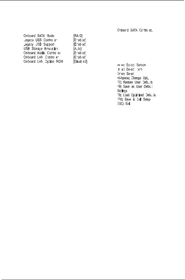
Parameter |
Description |
Option |
|||||||||||||
|
|
|
|
|
|
|
|
|
|
|
|
|
|
|
|
Onboard SATA Controller |
Enables or disables the onboard SATA controller. |
Enabled |
|||||||||||||
|
|
|
|
|
|
|
|
|
|
|
|
Disabled |
|||
|
|
|
|
|
|
|
|
|
|
|
|
|
|
|
|
Onboard SATA Mode |
Select an operating mode for the onboard SATA. |
AHCI |
|||||||||||||
|
|
|
|
|
|
|
|
|
|
|
|
Native IDE |
|||
|
|
|
|
|
|
|
|
|
|
|
|
|
|
|
|
Legacy USB Controller |
Enables or disables support for legacy USB devices |
Enabled |
|||||||||||||
|
|
|
|
|
|
|
|
|
|
|
|
Disabled |
|||
|
|
|
|
|
|
|
|
|
|
|
|
|
|
|
|
Legacy USB Support |
Enables or disables support for legacy USB devices. |
Enabled |
|||||||||||||
|
|
|
|
|
|
|
|
|
|
|
|
Disabled |
|||
|
|
|
|
|
|
|
|
|
|
|
|
|
|
|
|
USB Storage Emulation |
Select emulation type for a USB mass storage device. |
Auto |
|||||||||||||
|
|
|
|
|
|
|
|
|
|
|
|
Floppy |
|||
|
|
|
|
|
|
|
|
|
|
|
|
Hard Disk |
|||
|
|
|
|
|
|
|
|
|
|
|
|
|
|
|
|
Onboard Audio Controller |
Enables or disables the onboard audio controller. |
Enabled |
|||||||||||||
|
|
|
|
|
|
|
|
|
|
|
|
Disabled |
|||
|
|
|
|
|
|
|
|
|
|
|
|
|
|
|
|
Onboard LAN Controller |
Enables or disables the onboard LAN controller. |
Enabled |
|||||||||||||
|
|
|
|
|
|
|
|
|
|
|
|
Disabled |
|||
|
|
|
|
|
|
|
|
|
|
|
|
|
|
|
|
Onboard LAN Option ROM |
Enables or disables the load of embedded option ROM for onboard |
Enabled |
|||||||||||||
|
|
|
network controller. |
Disabled |
|||||||||||
|
|
|
|
|
|
|
|
|
|
|
|
|
|
|
|
14 |
Chapter 2 |
PC Health Status
|
|
|
|
|
|
|
|
|
|
|
|
|
|
|
|
|
|
|
|
|
|
|
|
|
|
|
|
|
|
|
|
|
|
|
|
|
|
|
|
|
|
|
|
|
|
|
|
|
|
|
|
|
|
|
|
|
|
|
|
|
|
|
|
|
|
|
|
|
|
|
|
|
|
|
|
|
|
|
|
|
|
|
|
|
|
|
|
|
|
|
|
|
|
|
|
|
|
|
|
|
|
|
|
|
|
|
|
|
|
|
|
|
|
|
|
|
|
|
|
|
|
|
|
|
|
|
|
|
|
|
|
|
|
|
|
|
|
|
|
|
|
|
|
|
|
|
|
|
|
|
|
|
|
|
|
|
|
|
|
|
|
|
|
|
|
|
|
|
|
|
|
|
|
|
|
|
|
|
|
|
|
|
|
|
|
|
|
|
|
|
|
|
|
|
|
|
|
|
|
|
|
|
|
|
|
|
|
|
|
|
|
|
|
|
|
|
|
|
|
|
|
|
|
|
|
|
|
|
|
|
|
|
|
|
|
|
|
|
|
|
|
|
|
|
|
|
|
|
|
|
|
|
|
|
|
|
|
|
|
|
|
|
|
|
|
|
|
|
|
|
|
|
|
|
|
|
|
|
|
|
|
|
|
|
|
|
|
|
|
|
|
|
|
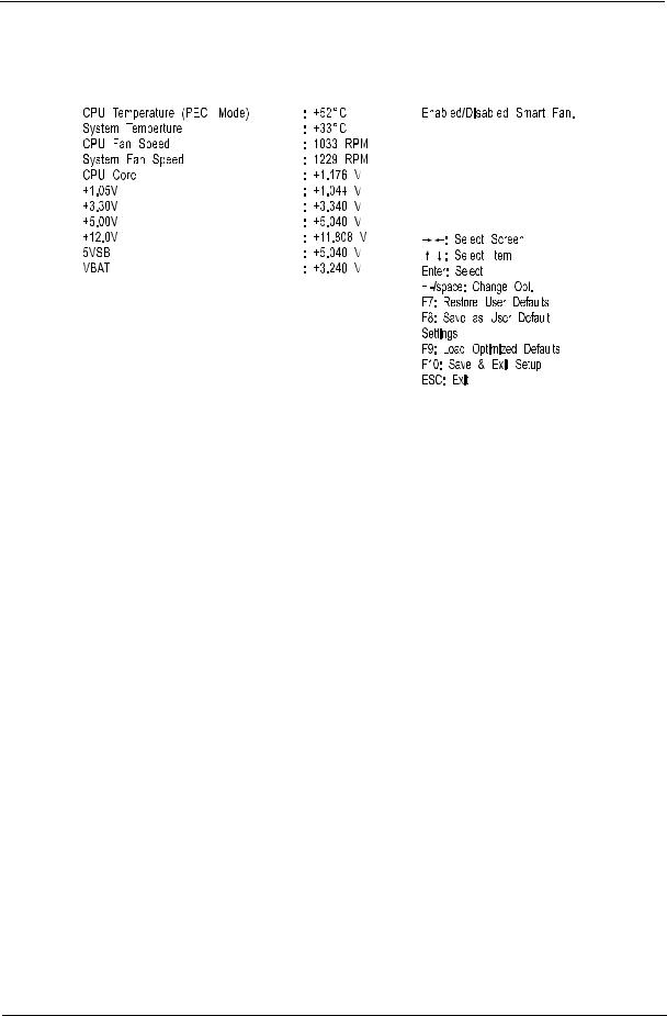
Parameter |
Description |
Option |
|||||||||||
|
|
|
|
|
|
|
|
|
|
|
|
|
|
CPU Temperature (PECI |
Set the shutdown temperature of the CPU. |
0°C |
|||||||||||
Mode) |
|
|
|
|
|
|
|
|
Disabled |
||||
|
|
|
|
|
|
|
|
|
|
|
|
|
|
System Temperature |
Set the shutdown temperature of the system. |
0°C |
|||||||||||
|
|
|
|
|
|
|
|
|
|
|
Disabled |
||
|
|
|
|
|
|
|
|
|
|
|
|
|
|
CPU Fan Speed |
These items let you monitor the parameters for critical voltages and fan |
|
|
|
|||||||||
System Fan Speed |
speeds. |
|
|
|
|||||||||
CPU Core |
|
|
|
|
|
|
|
|
|
|
|
||
+1.05V |
|
|
|
|
|
|
|
|
|
|
|
||
+3.30V |
|
|
|
|
|
|
|
|
|
|
|
||
+5.00V |
|
|
|
|
|
|
|
|
|
|
|
||
+12.0V |
|
|
|
|
|
|
|
|
|
|
|
||
5VSB |
|
|
|
|
|
|
|
|
|
|
|
||
VBAT |
|
|
|
|
|
|
|
|
|
|
|
||
|
|
|
|
|
|
|
|
|
|
|
|
|
|
Smart Fan |
Enables or disables the smart system fan control function. |
Enabled |
|||||||||||
|
|
|
|
|
|
|
|
|
|
|
Disabled |
||
|
|
|
|
|
|
|
|
|
|
|
|
|
|
Chapter 2 |
15 |
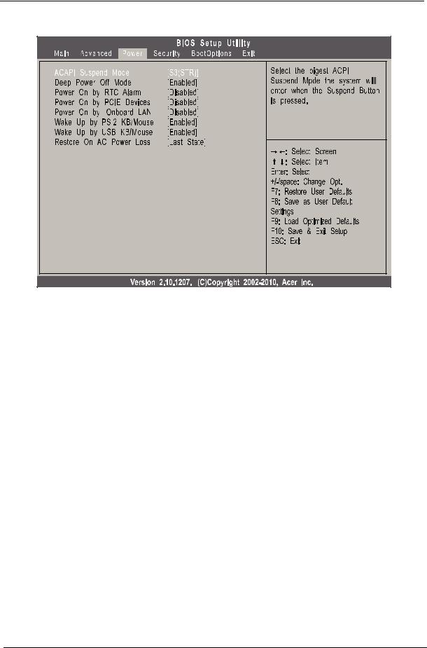
Power |
Parameter |
Description |
Option |
|
|
|
ACPI Suspend Mode |
Select an ACPI state. |
S3 (STR) |
|
|
S1 (POS) |
|
|
|
Deep Power Off Mode |
Enables or disables the deep power off mode. |
Enabled |
|
|
Disabled |
|
|
|
Power On by RTC Alarm |
Enables or disables real time clock (RTC) to generate a wake event. |
Enabled |
|
|
Disabled |
|
|
|
Power On by PCIE Devices |
Enables or disables to wake up the system from a power saving mode |
Enabled |
|
through an event on a PCI Express device. |
Disabled |
|
|
|
Power On by Onboard LAN |
Enables or disables an onboard LAN controller to generate a wake |
Enabled |
|
event. |
Disabled |
|
|
|
Wake Up by PS/2 KB/Mouse |
Enables or disables to wake up the system from a power saving mode |
Enabled |
|
using a PS2 keyboard or mouse. |
Disabled |
|
|
|
Wake Up by USB KB/Mouse |
Enables or disables to wake up the system from a power saving mode |
Enabled |
|
using a USB keyboard or mouse. |
Disabled |
|
|
|
Restore On AC Power Loss |
Enables or disables the system to reboot after a power failure or |
Power Off |
|
interrupt occurs. |
Power On |
|
|
Last State |
|
|
|
16 |
Chapter 2 |
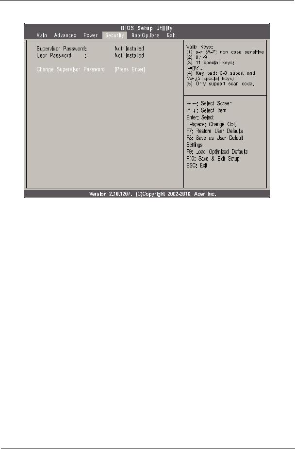
Security |
Parameter |
Description |
|
|
Supervisor Password |
Indicates the status of the supervisor password. |
|
|
User Password |
Indicates the status of the user password. |
|
|
Change Supervisor |
Supervisor password prevents unauthorized access to the BIOS Setup Utility. |
Password |
Press Enter to change the Supervisor password. |
|
|
Change User Password |
Press Enter to change the User password. |
|
|
Setting a system password
1.Use the up/down arrow keys to select a password parameter (Change Supervisor Password or Change User Password) menu then press Enter.
A password box will appear.
2.Type a password then press Enter.
The password may consist up to six alphanumeric characters (A-Z, a-z, 0-9)
3.Retype the password to verify the first entry then press Enter again.
4.Press F10.
5.Select Yes to save the new password and close the Setup Utility.
Changing the system password
1.Use the up/down arrow keys to select password parameter (Change Supervisor Password or Change User Password) menu then press Enter.
2.Type the original password then press Enter.
3.Type a new password then press Enter.
4.Retype the password to verify the first entry then press Enter again.
5.Press F10.
6.Select Yes to save the new password and close the Setup Utility.
Removing a system password
Chapter 2 |
17 |
1.Use the up/down arrow keys to select password parameter (Change Supervisor Password or Change User Password) menu then press Enter.
2.Enter the current password then press Enter.
3.Press Enter twice without entering anything in the password fields.
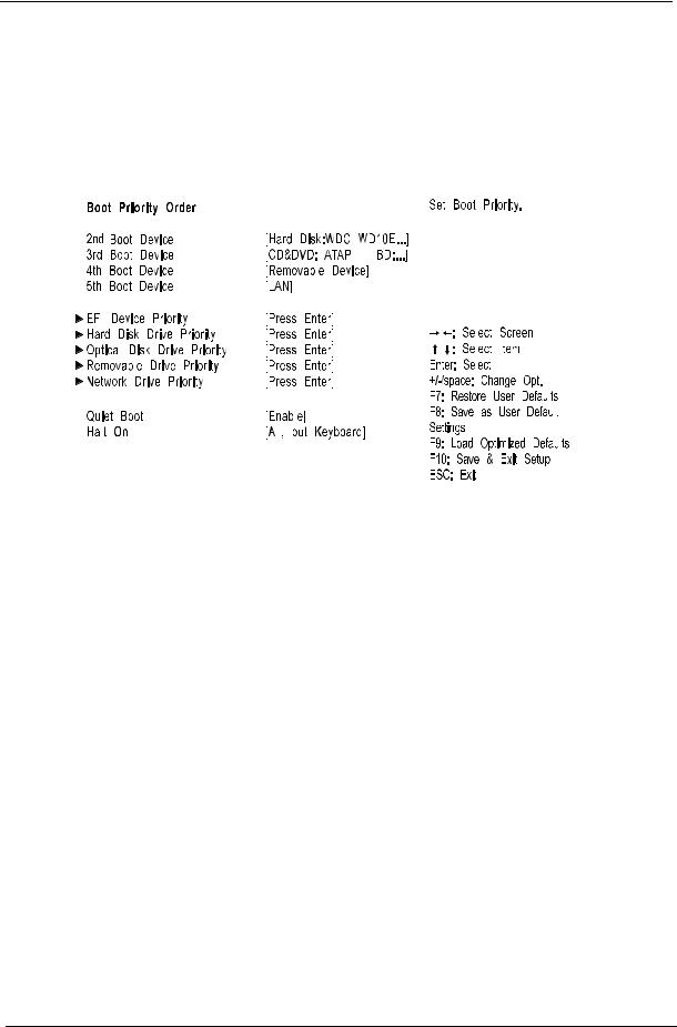
Boot Options
|
|
|
|
|
|
|
|
|
|
|
|
|
|
|
|
|
|
|
|
|
|
|
|
|
|
|
|
|
|
|
|
|
|
|
|
|
|
|
|
|
|
|
|
|
|
|
|
|
|
|
|
|
|
|
|
|
|
|
|
|
|
|
|
|
|
|
|
|
|
|
|
|
|
|
|
|
|
|
|
|
|
|
|
|
|
|
|
|
|
|
|
|
|
|
|
|
|
|
|
|
|
|
|
|
|
|
|
|
|
|
|
|
|
|
|
|
|
|
|
|
|
|
|
|
|
|
|
|
|
|
|
|
|
|
|
|
|
|
|
|
|
|
|
|
|
|
|
|
|
|
|
|
|
|
|
|
|
|
|
|
|
|
|
|
|
|
|
|
|
|
|
|
|
|
|
|
|
|
|
|
|
|
|
|
|
|
|
|
|
|
|
|
|
|
|
|
|
|
|
|
|
|
|
|
|
|
|
|
|
|
|
|
|
|
|
|
|
|
|
|
|
|
|
|
|
|
|
|
|
|
|
|
|
|
|
|
|
|
|
|
|
|
|
|
|
|
|
|
|
|
|
|
|
|
|
|
|
|
|
|
|
|
|
|
|
|
|
|
|
|
|
|
|
|
|
|
|
|
|
|
|
|
|
|
|
|
|
|
|
|
|
|
|
|
|
|
|
|
|
|
|
|
|
|
|
|
|
|
|
|
|
|
|
|
|
|
|
|
|
|
|
|
|
|
|
|
|
|
|
|
|
|
|
|
|
|
|
|
|
|
|
|
|
|
|
|
|
|
|
|
|
|
|
|
|
|
|
|
|
|
|
|
|
|
|
|
|
|
|
|
|
|
|
|
|
|
|
|
|
|
|
|
|
|
|
|
|
|
|
|
|
|
|
|
|
|
|
|
|
|
|
|
|
|
|
|
|
|
|
|
|
|
|
|
|
|
|
|
|
|
|
|
|
|
|
|
|
|
|
|
|
Parameter |
Description |
Option |
|||||||||||||||
|
|
|
|
|
|
|
|
|
|
|
|
|
|
|
|
|
|
1st/2nd/3rd/4th/5th Boot |
Specifies the boot order from the available devices. |
Hard Disk |
|||||||||||||||
Device |
|
|
|
|
|
|
|
|
|
|
CD/DVD |
||||||
|
|
|
|
|
|
|
|
|
|
|
|
|
|
|
Removable |
||
|
|
|
|
|
|
|
|
|
|
|
|
|
|
|
Device |
||
|
|
|
|
|
|
|
|
|
|
|
|
|
|
|
LAN |
||
|
|
|
|
|
|
|
|
|
|
|
|
|
|
|
|
|
|
EFI Device Priority |
Press Enter to access the EFI Device Priority submenu and specify the boot device priority |
||||||||||||||||
|
|
|
|
|
sequence from available EFI devices. |
|
|
|
|||||||||
|
|
|
|
|
|
|
|
|
|
|
|
|
|
|
|
|
|
Hard Disk Drive Priority |
Press Enter to access the Hard Disk Drive Priority submenu and specify the boot device |
||||||||||||||||
|
|
|
|
|
priority sequence from available hard drives. |
|
|
|
|||||||||
|
|
|
|
|
|
|
|
|
|
|
|
|
|
|
|
|
|
Optical Disk Drive Priority |
Press Enter to access the Optical Disk Drive Priority submenu and specify the boot device |
||||||||||||||||
|
|
|
|
|
priority sequence from available CD/DVD drives. |
|
|
|
|||||||||
|
|
|
|
|
|
|
|
|
|
|
|
|
|
|
|
|
|
Removable Device Priority |
Press Enter to access the Removable Device Priority submenu and specify the boot device |
||||||||||||||||
|
|
|
|
|
priority sequence from available removable drives. |
|
|
|
|||||||||
|
|
|
|
|
|
|
|
|
|
|
|
|
|
|
|
|
|
Network Device Priority |
Press Enter to access the Network Device Priority submenu and specify the boot sequence |
||||||||||||||||
|
|
|
|
|
from available network devices. |
|
|
|
|||||||||
|
|
|
|
|
|
|
|
|
|
|
|
|
|
|
|
|
|
Quiet Boot |
When enabled, the BIOS splash screen displays during startup. |
Enabled |
|||||||||||||||
|
|
|
|
|
When disabled, the diagnostic screen displays during startup. |
Disabled |
|||||||||||
|
|
|
|
|
|
|
|
|
|
|
|
|
|
|
|
|
|
Halt On |
Determines whether the system will stop for an error during the POST. |
All, but |
|||||||||||||||
|
|
|
|
|
|
|
|
|
|
|
|
|
|
|
keyboard |
||
|
|
|
|
|
|
|
|
|
|
|
|
|
|
|
No Errors |
||
|
|
|
|
|
|
|
|
|
|
|
|
|
|
|
All Errors |
||
|
|
|
|
|
|
|
|
|
|
|
|
|
|
|
|
|
|
18 |
Chapter 2 |
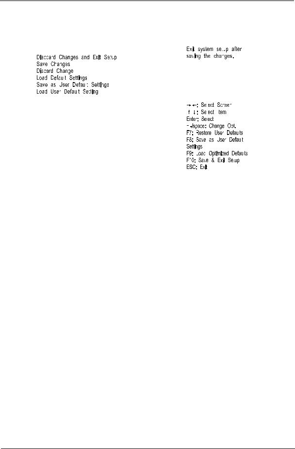
Exit
|
|
|
|
|
|
|
|
|
|
|
|
|
|
|
|
|
|
|
|
|
|
|
|
|
|
|
|
|
|
|
|
|
|
|
|
|
|
|
|
|
|
|
|
|
|
|
|
|
|
|
|
|
|
|
|
|
|
|
|
|
|
|
|
|
|
|
|
|
|
|
|
|
|
|
|
|
|
|
|
|
|
|
|
|
|
|
|
|
|
|
|
|
|
|
|
|
|
|
|
|
|
|
|
|
|
|
|
|
|
|
|
|
|
|
|
|
|
|
|
|
|
|
|
|
|
|
|
|
|
|
|
|
|
|
|
|
|
|
|
|
|
|
|
|
|
|
|
|
|
|
|
|
|
|
|
|
|
|
|
|
|
|
|
|
|
|
|
|
|
|
|
|
|
|
|
|
|
|
|
|
|
|
|
|
|
|
|
|
|
|
|
|
|
|
|
|
|
|
|
|
|
|
|
|
|
|
|
|
|
|
|
|
|
|
|
|
|
|
|
|
|
|
|
|
|
|
|
|
|
|
|
|
|
|
|
|
|
|
|
|
|
|
|
|
|
|
|
|
|
|
|
|
|
|
|
|
|
|
|
|
|
|
|
|
|
|
|
|
|
|
|
|
|
|
|
|
|
|
|
|
|
|
|
|
|
|
|
|
|
|
|
|
|
|
|
|
|
|
|
|
|
|
|
|
|
|
|
|
|
|
|
|
|
|
|
|
|
|
|
|
|
|
|
|
|
|
|
|
|
|
|
|
|
|
|
|
|
|
|
|
|
|
|
|
|
|
|
|
|
Parameter |
Description |
||||||||||||
|
|
|
|
|
|
|
|
|
|
|
|
|
|
Save & Exit Setup |
When you have completed the system configuration changes, select this option to leave the |
||||||||||||
|
|
|
BIOS Setup Utility and reboot the computer, so the new system configuration parameters can |
||||||||||
|
|
|
take effect. Select Save & Exit Setup from the Exit menu and press Enter. |
||||||||||
Discard Changes and Exit |
Select this option to quit the BIOS Setup Utility without making any permanent changes to the |
||||||||||||
Setup |
system configuration, and reboot the computer. Select Discard Changes and Exit Setup from |
||||||||||||
|
|
|
the Exit menu and press Enter. |
||||||||||
Save Changes |
Select this option and press Enter to save all the changes and return to the BIOS Setup Utility. |
||||||||||||
|
|
|
|
|
|
|
|
|
|
|
|
|
|
Discard Change |
Select this option and press Enter to discard all the changes and return to the BIOS Setup |
||||||||||||
|
|
|
Utility. |
||||||||||
|
|
|
|
|
|
|
|
|
|
|
|
|
|
Load Default Settings |
To set this feature, select Load Default Settings from the Exit menu and press Enter. Then, |
||||||||||||
|
|
|
select OK to allow the BIOS to automatically load optimal defaults to the BIOS settings. The |
||||||||||
|
|
|
Optimal settings are designed for maximum system performance, but may not work best for all |
||||||||||
|
|
|
computer applications. |
||||||||||
|
|
|
|
|
|
|
|
|
|
|
|
|
|
Save as User Default |
Select this option and press Enter to save changes that you have made as user defaults. |
||||||||||||
Settings |
|
|
|
|
|
|
|
|
|
|
|
||
|
|
|
|
|
|
|
|
|
|
|
|
|
|
Load User Default Settings |
Select this option and press Enter to restore user defaults. |
||||||||||||
|
|
|
|
|
|
|
|
|
|
|
|
|
|
Chapter 2 |
19 |

20 |
Chapter 2 |

Chapter 3
System Disassembly
This chapter contains step-by-step procedures on how to disassemble the desktop computer for maintenance and troubleshooting.
Disassembly Requirements
To disassemble the computer, you need the following tools:
•Wrist grounding strap and conductive mat for preventing electrostatic discharge
•Flat-blade screwdriver
•Philips screwdriver
•Hex screwdriver
•Plastic flat-blade screwdriver
•Plastic tweezers
NOTE: The screws for the different components vary in size. During the disassembly process, group the screws with the corresponding components to avoid mismatch when putting back the components.
Pre-disassembly Procedure
Before proceeding with the disassembly procedure, perform the steps listed below:
1.Turn off the system and all the peripherals connected to it.
2.Unplug the power cord from the power outlets.
3.Unplug the power cord from the system.
4.Unplug all peripheral cables from the system.
5.Place the system unit on a flat, stable surface.
Chapter 3 |
21 |

Removing the Side Panel
1.Remove the two screws located on the rear edge of the side panel.
2.Slide the side panel toward the back of the chassis until the tabs on the cover disengage with the slots on the chassis, then lift the side panel away from the server and put it aside for reinstallation later.
22 |
Chapter 3 |
Loading...