


 Loading...
Aspire 9800 Series
Service Guide
Service guide files and updates are available on the ACER/CSD web; for more information, please refer to http://csd.acer.com.tw
PRINTED IN TAIWAN

Revision History
Please refer to the table below for the updates made on Aspire 9800 service guide.
Date |
Chapter |
Updates |
|
|
|
|
|
|
|
|
|
|
|
|
II

Copyright
Copyright © 2006 by Acer Incorporated. All rights reserved. No part of this publication may be reproduced, transmitted, transcribed, stored in a retrieval system, or translated into any language or computer language, in any form or by any means, electronic, mechanical, magnetic, optical, chemical, manual or otherwise, without the prior written permission of Acer Incorporated.
Disclaimer
The information in this guide is subject to change without notice.
Acer Incorporated makes no representations or warranties, either expressed or implied, with respect to the contents hereof and specifically disclaims any warranties of merchantability or fitness for any particular purpose. Any Acer Incorporated software described in this manual is sold or licensed "as is". Should the programs prove defective following their purchase, the buyer (and not Acer Incorporated, its distributor, or its dealer) assumes the entire cost of all necessary servicing, repair, and any incidental or consequential damages resulting from any defect in the software.
Acer is a registered trademark of Acer Corporation. Intel is a registered trademark of Intel Corporation.
Pentium and Pentium II/III are trademarks of Intel Corporation.
Other brand and product names are trademarks and/or registered trademarks of their respective holders.
III

Conventions
The following conventions are used in this manual:
SCREEN MESSAGES |
Denotes actual messages that appear |
|
on screen. |
|
|
NOTE |
Gives bits and pieces of additional |
|
information related to the current |
|
topic. |
|
|
WARNING |
Alerts you to any damage that might |
|
result from doing or not doing specific |
|
actions. |
|
|
CAUTION |
Gives precautionary measures to |
|
avoid possible hardware or software |
|
problems. |
|
|
IMPORTANT |
Reminds you to do specific actions |
|
relevant to the accomplishment of |
|
procedures. |
|
|
IV

Preface
Before using this information and the product it supports, please read the following general information.
1.This Service Guide provides you with all technical information relating to the BASIC CONFIGURATION decided for Acer's "global" product offering. To better fit local market requirements and enhance product competitiveness, your regional office MAY have decided to extend the functionality of a machine (e.g. add-on card, modem, or extra memory capability). These LOCALIZED FEATURES will NOT be covered in this generic service guide. In such cases, please contact your regional offices or the responsible personnel/channel to provide you with further technical details.
2.Please note WHEN ORDERING FRU PARTS, that you should check the most up-to-date information available on your regional web or channel. If, for whatever reason, a part number change is made, it will not be noted in the printed Service Guide. For ACER-AUTHORIZED SERVICE PROVIDERS, your Acer office may have a DIFFERENT part number code to those given in the FRU list of this printed Service Guide. You MUST use the list provided by your regional Acer office to order FRU parts for repair and service of customer machines.
V

VI

Chapter 1
System Specifications
Features
Below is a brief summary of the computer’s many feature:
Operating system
Genuine Windowsl® VistaTM Capable
Genuine Windowsl® XP Home Edition (Service Pack 2) Genuine Windowsl® XP Media Center Edition 2005 (Rollup 2)
NOTE: Windowsl® VistaTM Capable PCs come with Windows® XP installed, and can be upgraded to
Windows® VistaTM. For more information on Windows® VistaTM and how to upgrade, go to: Microsoft.com/windowsvista.
Platform and memroy
Intel® Centrino® Duo mobile technology, featuring:
τIntel® CoreTM Duo processor T2300/T2400/T2500/T2600 (2 MB L2 cache, 1.66/1.83/2/2.16 GHz, 667 MHz FSB) or higher
τIntel® 945PM Express chipset
Integrated Intel® PRO/Wireless 3945ABG network connection (dual-band tri-mode 802.11a/b/g) Wi-Fi CERTIFIEDTM solution, supporting Acer SignalUpTM wireless technology
Core logic: Intel® 945PM+ICH7M (north bridge+ south bridge)
Up to 2GB of DDR2 677 MHz memory, upgradeable to 4GB using two soDIMM moules (dualchannel support)
Display and graphics
20.1” WSXGA+ high-brightness Acer CrystalBriteTM TFT LCD, 1680 x 1050 pixel resolution, 6 lamps
19” WXGA+ high-brightness Acer CrystalBriteTM TFT LCD, 1440 x 900 pixel resolution, 4 lamps 16 ms typical of/off and 8 ms average gray-to-gray response time
Simultaneous multi-window viewing via Acer VistaTM supported
NVIDIA® GeForce® Go 7600 with up to 512MB TurboCacheTM (256 MB of dedicated GDDR2 VRAM and up to 256 MB of shared system memory) or,
NVIDIA® GeForce® Go 7300 with up to 256MB TurboCacheTM (128 MB of dedicated GDDR2 VRAM and up to 128 MB of shared system memory)
Supporting NVIDIA® PureVideoTM technology (WMV HD, High-Definition MPEG-2 Hardware Acceleration, integrated HDTV encoder) dual-link DVI, Microsoft® DirectX® 9.0, Shader Model 3.0, OpenEXR Hight Dynamic Range (HDR) technology, NVIDIA® PowerMizerTM 6.0 and PCI Express®
Dual independent display
16.7 million colors (20.1” LCD model)
16.2 million colors (19” LCD model) MPEG-2/DVD hardware-assisted capability S-video/TV-out (NTSC/PAL) support
Chapter 1 |
1 |

DVI-D (ture digital video interface) with HDCP (High-bandwidth Digital Content Protection) support Acer ArcadeTM featuring Acer CinemaVisionTM and Acer ClearVision technologies
TV-tuner
Acer TV-tunver options:
τAnalog TV-tuner supporting hardware MPEG-2 stream encding
τDigital and analog hybrid TV-tuner supporting hardware MPEG-2 stream encoding τDigital and analog hybrid TV-tuner supporting software MPEG-2 stream encoding Analog TV-tuner supporting international analog TV standards (NTSC/PAL/SECAM)
Digital TV-tuner supporting DVB-T (Digital Video Broadcasting Terrestrial) standard (6 MHz to 8MHz)
TV-tuner I/O:
τRF jack for digital/analog TV antenna cable input
τAV-in port for composite/S-video/line-in audio/video input TV-tuner cables:
τPAL cable for digital/analog TV input, PAL/SECAM to NTSC port converter τMini DIN cable: RCA jack and S-video port for audio/video input
Acer DVB-T antenna (UHF/VHF reception) supporting Acer SignaUpTM wireless technology
Audio
Audio system with two built-in Acer 3DSonic (1.5W) stereo speakers and one Acer BasSonic Subwoofer
Dolby® Digital Live and DTS Neo: PC support Intel® High Definition audio support
S/PDIF (Sony/Philips Digital Interface) support for digital speakers (1.5W) Sound Blaster ProTM and MS Sound compatible
Two built-in stereo microphone
Storage subsystem
One or two 80/100/120 GB Serial ATA hard disk drive, supporting software RAID 0/1 Optical drive options: DVD-Super Mulit double-layer drive (slot-load)
5-in-1 card reader, supporting Secure Digital (SD), MultiMediaCard (MMC), Memory Stick® (MS), Memory Stick PROTM (MS PRO), xD-Picture CardTM (xD)
Input devices
88/89-key Acer FineTouchTM keyboard with 5-degree curve Touchpad with 4-way scroll button
Four easy-launch buttons
Two front-access switches: WLAN LED and Bluetooth® LED-switches (for selected models)
Communication
Acer Video Conference, featuring Voice and Video over Internet Protocol (VVoIP) support via Acer OrbiCamTM and optional Acer Bluetooth® VoIP phone
Acer OrbiCamTM 1.3 megapixel CMOS camera, featuring: τ30 degree ergonomic rotation
τAcer VisageOnTM technology
2 |
Chapter 1 |

τAcer PrimaLiteTM technology
Modem: 56K ITU V.92 modem with PTT approval; wake-on ring ready LAN: gigabit Ethernet; wake-on-LAN ready
WPAN: Bluetooth® 2.0+EDR (Enhanced Data Rate)
WLAN: Intel® PRO/Wireless 3945ABG network connection (dual-band tri-mode 802.11a/b/g) WiFi® CERTIFIEDTM solution, supporting Acer SignalUpTM wireless technology
I/O Ports
ExpressCardTM/54 slot PC Card slot (one Type II)
5-in-1 card reader (SD/MMC/MS/MS PRO/xD) Four USB 2.0 ports
DVI-D port with HDCP support IEEE 1394 port
Consumer infrared (CIR) port Fast infrared (FIR) port External display (VGA) port
S-video/TV-out (NTSC/PAL) port AV-in port
TV-tuner antenna-in port Headphones/speaker/line-out port with S/PDIF support Microphone-in jack
Line-in jack Parallel port Serial port
Ethernet (RJ-45) port Modem (RJ-11) port
DC-in jack for AC adaptor
NOTE: HDCP is acronym for High-bandwidth Digital Content Protection. An encryption system for enforcing digital rights management (DRM) over DVI and HDMI interfaces
Environment
Temperature:
τoperating: 5 ° C to 35 ° C
τNon-operating: -20 ° C to 65 °C
Humidity (non-condensing):
τoperating: 20%~80% τNon-operating: 20%~80%
Chapter 1 |
3 |

System Block Diagram
|
|
|
|
|
|
|
|
|
|
|
|
|
|
|
|
|
|
|
|
|
|
|
|
|
CPU |
|
|
|
|
|
|
|
|
|
|
|
|
|
|
|
|
|
|
|
|
|
|
|
|
|
|
|
|
|
|
|
|
|
|
|
|
|
|
|
|
|
|
|
|
|
|
|
|
|
|
|
|||||||||||||||||||
|
|
|
|
|
|
|
|
|
|
|
|
|
|
|
|
|
|
|
|
|
YONAH/MEROM |
|
|
|
|
|
|
|
|
|
|
|
|
|
|
|
|
|
|
|
|
|
|
|
|
|
|
|
|
|
|
|
|
|
|
|
|
|
|
|
|
|
|
|
|
|
|
|
|
|
|
|
|||||||||||||||||||||||
|
|
HDMI |
|
|
|
|
|
|
|
|
|
|
|
|
|
|
|
|
|
|
|
|
|
31W/34W |
|
|
|
|
|
|
|
|
|
|
|
|
|
|
|
|
|
|
|
|
|
|
|
|
|
|
|
|
|
|
|
|
|
|
|
|
|
|
|
|
|
|
|
|
|
|
|
|
|
|
|
||||||||||||||||||||
|
|
|
|
|
|
|
|
|
|
|
|
|
|
|
|
|
|
|
|
|
|
|
|
|
|
|
|
|
|
|
|
|
|
|
|
|
|
|
|
|
|
|
|
|
|
|
|
|
|
|
|
|
|
|
|
|
|
|
|
|
|
|
|
|
|
|
|
|
|
|
|
|
|
||||||||||||||||||||||
|
|
|
|
|
|
|
|
|
|
|
|
|
|
|
|
|
|
|
|
|
|
|
|
|
|
|
|
|
|
|
|
|
|
|
|
|
|
|
M P.14-17 |
|
|
|
|
|
|
|
|
|
|
CLK GEN |
|
|
|
|
|
|
|
|
|
|
|
THERMAL SENSOR |
|
|
|
|
|
|
|
|
|
|
|
|
|
|
|||||||||||||||||||
|
|
M P.38 |
|
|
|
|
|
|
|
|
|
|
|
|
|
|
|
|
|
|
|
|
|
|
|
|
|
|
|
|
|
|
|
|
|
|
|
|
|
|
|
|
|
|
|
|
|
|
|
|
ICS9LPR316 |
|
|
|
|
|
|
|
|
|
|
|
|
|
|
|
& FAN |
|
|
|
|
|
|
|
|
|
|
|
|
|
|
|
|
||||||||||||
|
|
|
|
|
|
|
|
|
|
|
|
|
|
|
|
|
|
|
|
|
|
|
|
|
|
|
|
|
|
|
|
|
|
|
|
|
|
|
|
|
|
|
|
|
|
|
|
|
|
|
|
|
|
|
|
|
|
|
|
|
|
M P.13 |
|
|
|
|
|
|
|
|
|
|
|
ADM1032 |
M P.18 |
|
|
|
|
|
|
|
|
|
|
|
|
|
|
||||||
|
|
LCM |
|
|
|
|
|
HDCP |
|
|
|
|
|
|
|
|
|
|
|
|
|
|
|
|
|
|
PSB |
|
|
|
|
|
|
|
|
|
|
|
|
|
|
|
|
|
|
|
|
|
|
|
|
|
|
|
|
|
|
|
|
|
|
|
|
|
|
|
|
|
|
|
|
|
|
|
|
|
|
|
|||||||||||||||||
|
|
|
|
|
|
|
ROM |
|
|
|
|
|
|
|
|
|
|
|
|
|
|
|
|
|
|
|
|
|
|
|
|
|
|
|
|
|
|
|
|
|
|
|
|
|
|
|
|
|
|
|
|
|
|
|
|
|
|
|
|
|
|
|
|
|
|
|
|
|
|
|
|
|
|
|
|
|
|||||||||||||||||||
|
|
M P.39 |
|
|
|
|
|
|
M P.30 |
|
|
|
|
|
|
|
|
|
|
|
|
|
|
|
|
|
|
|
|
|
|
|
|
|
|
|
|
|
|
|
|
|
|
DDR2 533/667 |
|
|
|
|
|
|
|
|
|
|
|
|
|
|
|
|
|
|
|
|
|
|
|
|
|
|
|
|
|
|
|
|
|
|
|
|
|
|
|
|
|
|
|
||||||||
|
|
|
|
|
|
|
|
|
|
|
|
|
|
|
|
|
|
|
|
|
|
|
|
|
|
|
|
|
|
|
|
|
|
|
|
|
|
|
|
|
|
|
|
|
|
|
|
|
|
|
|
|
|
DDR2_SODIMM0 |
|
|
|
|
|
|
|
|
|
|
|
|
|
|
|
|
|
|
|
LOM |
|
|
|
|
|||||||||||||||||
|
|
DVI |
|
|
|
|
|
VGA |
|
|
|
|
|
|
|
|
|
|
|
North Bridge |
|
|
|
|
|
|
|
|
|
|
|
|
|
|
|
|
|
|
|
M P.25 |
|
|
|
|
|
|
|
|
|
|
|
|
|
|
|
|
|
|
Controller |
|
|
|
|
||||||||||||||||||||||||||||||||
|
|
|
|
|
|
|
|
|
|
PCIE |
|
|
|
|
|
|
|
|
|
|
|
|
|
|
|
|
|
|
|
|
|
|
|
|
|
|
|
|
|
|
|
|
|
|
|
|
|
|
|
|
|
|
|
|
|
MARVELL |
|
|
|
|
|||||||||||||||||||||||||||||||||||
|
|
M P.38 |
|
|
|
|
Controller |
|
|
|
|
|
|
|
|
|
|
|
Calistoga |
|
|
|
|
|
|
|
|
|
|
|
|
|
|
|
|
|
|
|
|
|
|
|
|
|
|
|
|
|
|
|
|
|
|
|
|
|
|
|
|
|
|
88E8055 M P.49 |
|
|
|||||||||||||||||||||||||||||||
|
|
|
|
|
|
|
NVG73M/G72MV |
|
|
|
|
|
|
|
|
|
|
1466 uFCBGA |
DDR2 533/667 |
|
DDR2_SODIMM1 |
|
|
|
|
|
|
|
|
|
|
|
|
|
|
|
|
|
|
|
|
|
|
|
|
|
|
|
|
||||||||||||||||||||||||||||||||||||||||||||||
|
|
|
|
|
|
|
|
|
|
|
|
|
|
|
|
|
|
|
|
|
|
|
|
|
|
|
|
|
|
|
|
|
|
|
|
|
|
|
|
|
|
|
|
|
|
|
|
|
|
|
|
||||||||||||||||||||||||||||||||||||||||||||
|
|
CRT |
|
|
|
|
|
|
|
|
M P.28-31 |
|
|
|
|
|
|
|
|
|
|
|
|
|
|
|
|
|
|
|
|
|
|
|
|
|
|
|
M P19-24 |
|
|
|
|
|
|
|
|
|
|
|
|
|
|
|
|
|
|
|
|
|
|
|
|
|
|
|
|
RJ45 |
|
|
|
|
|||||||||||||||||||||||
|
|
|
|
|
|
|
|
|
|
|
|
|
|
|
|
|
|
|
|
|
|
|
|
|
|
|
|
|
|
|
|
|
|
|
|
|
|
|
|
|
|
|
|
|
|
|
|
|
|
|
|
|
|
|
|
|
|
M P.26 |
|
|
|
|
|
|
|
|
|
|
|
|
|
|
|
|
|
|
|
|
|
|
|
||||||||||||||
|
|
M P.37 |
|
|
|
|
|
|
|
|
|
|
|
|
|
|
|
|
|
|
|
|
|
|
|
|
|
|
|
|
|
|
|
|
|
|
|
|
|
|
|
|
|
|
|
|
|
|
|
|
|
|
|
|
|
|
|
|
|
|
|
|
|
|
|
|
|
|
|
|
|
|
|
|
|
|
|
|
|
|
|
|
|
|
|
|
CONN |
|
|
|
|
||||
|
|
|
|
|
|
|
|
|
|
VRAM |
|
|
|
|
|
|
|
|
|
|
|
|
|
|
|
|
|
|
|
|
|
|
|
|
|
|
|
|
|
|
|
|
|
|
|
|
|
|
|
|
|
|
|
|
|
|
|
|
|
|
|
|
|
|
|
|
|
|
|
|
|
|
|
|
|
|
|
|
|
|
|
|
|
|
|
|
|||||||||
|
|
|
|
|
|
|
|
|
|
* 8(4) PCS |
|
|
|
|
|
|
|
|
|
|
|
|
|
|
|
DMI |
|
|
|
|
|
|
|
|
|
|
|
|
|
|
|
|
|
|
|
|
|
|
|
|
|
|
|
|
|
|
|
|
|
|
|
|
|
|
|
|
|
|
|
|
|
|
M P.50 |
|
|
||||||||||||||||||||
|
|
|
|
|
|
|
|
|
|
|
|
|
|
|
|
|
|
|
|
|
|
|
|
|
|
|
|
|
|
|
|
|
|
|
|
|
|
|
|
|
|
|
|
|
|
|
|
|
|
|
|
|
|
|
|
|
|
|
|
|
|
|
|
|
|
|
|
|
|
|
|
|
|
|
|
|
|
||||||||||||||||||
|
|
S-Video |
|
|
|
|
|
|
|
|
M P32-36 |
|
|
|
|
|
|
|
|
|
|
|
|
|
|
|
|
|
|
|
|
|
|
|
|
|
|
|
|
|
|
|
|
|
|
|
|
|
|
|
|
|
|
|
|
|
|
|
|
|
|
|
|
|
|
|
|
|
|
|
|
|
|
|
|
|
|
||||||||||||||||||
|
|
|
|
|
|
|
|
|
|
|
|
|
|
|
|
|
|
|
|
|
|
|
|
|
|
|
|
|
|
|
|
|
|
|
|
|
|
|
|
|
|
|
|
|
|
|
|
|
|
|
|
|
|
|
|
|
|
|
|
|
|
|
|
|
|
|
|
|
|
|
|
|
|
|
|
|
|
|
|
|
|
|
|
|
|
|
|
|
|
|
|||||
|
|
|
|
|
|
|
|
|
|
|
|
|
|
|
|
|
|
|
|
|
|
|
|
|
|
|
|
|
|
|
|
|
|
|
|
|
|
|
|
|
|
|
|
|
|
|
|
|
|
|
|
|
|
|
|
|
|
|
|
|
|
|
|
|
|
|
|
|
|
|
|
|
|
|
|
|
|
|
|
|
|
|
|
|
|
|
|||||||||
|
|
M P.38 |
|
|
|
|
|
|
|
|
|
|
|
|
|
|
|
|
|
|
|
|
|
|
|
|
|
|
|
|
|
|
|
|
|
|
|
|
|
|
|
|
|
|
|
|
|
|
|
|
|
|
|
|
|
|
|
|
|
|
|
|
|
|
|
|
|
|
|
|
|
|
|
|
|
|
|
|
|
|
|
|
|
|
|
|
|
|
|
|
|
|
|
|
|
|
|
|
|
|
|
|
|
OPTION |
|
|
|
|
|
|
|
|
|
|
|
|
|
|
|
|
|
|
|
|
|
|
|
|
|
|
|
|
|
|
|
|
|
|
PCI_Express Bus |
|
|
|
|
|
|
|
|
|
|
|
|
|
|
|
|
|
|
|
|
|
|
|
|
|
|
|
|
|
|
|
|
|
|
|
|
|
|
||||||||||||||
|
|
|
|
|
|
|
|
|
|
|
|
|
|
|
|
|
|
|
|
|
|
|
|
|
|
|
|
|
|
|
|
|
|
|
|
|
|
|
|
|
|
|
|
|
|
|
|
|
|
|
|
|
|
|
|
|
|
|
|
|
|
|
|
|
|
|
|
|
|
|
|
|
|
|
|
|
|
|
|
||||||||||||||||
|
PWR Board |
|
|
|
|
|
|
|
HDD |
|
|
|
|
|
|
|
|
|
|
|
South Bridge |
|
|
|
|
|
|
|
|
|
|
|
|
|
|
|
|
|
|
|
|
|
|
|
|
|
|
|
|
|
|
|
|
|
|
|
|
|
|
|
|
|
|
|
|
|
|
|
|
|
|
|
|||||||||||||||||||||||
|
|
|
|
|
|
|
|
|
M P.53 |
SATA |
|
|
|
|
|
|
|
USB 2.0 |
|
|
USB2.0 PORT |
|
|
|
|
|
|
|
|
|
BLUETOOTH |
|
|
|
|
|
|
|
Mini Card |
|
|
|
M P.51 |
|
|
|
|
||||||||||||||||||||||||||||||||||||||||||||||||
Batt Charger |
|
|
|
|
|
|
|
|
|
|
|
|
|
|
|
|
|
|
|
|
|
ICH7-M |
|
|
|
|
|
|
DSC |
|
|
|
|
Express Card |
|
|
|
|
|
Mini Card |
|
||||||||||||||||||||||||||||||||||||||||||||||||||||||
|
|
|
|
|
|
|
|
|
|
|
|
|
|
|
|
|
|
|
|
|
|
|
|
|
|
|
|
|
|
x4 |
|
|
|
|
|
|
|
|
VER 2.0 |
|
|
|
|
|
|
|
|||||||||||||||||||||||||||||||||||||||||||||||||
|
|
|
|
|
|
|
|
|
|
|
|
|
|
|
|
|
|
|
|
|
|
|
|
|
652 BGA |
PCI Bus |
|
|
|
M P54 & I P.1 |
|
|
|
|
|
M P.39 |
|
|
|
M P.55 |
|
|
|
|
M P.46 |
|
|
|
|
M P.51 |
|
|
|
|
(No USB) |
|
|||||||||||||||||||||||||||||||||||||||
|
|
|
|
|
|
|
|
CD-ROM |
|
Ultra ATA-100 |
|
|
|
|
|
|
|
|
|
|
|
|
|
|
|
|
|
|
|
|
|
|
|
|
|
|
|
|
|
|
|
|
|
|
|
|
|||||||||||||||||||||||||||||||||||||||||||||||||
|
|
|
|
|
|
|
|
|
|
|
M P.53 |
|
|
|
|
|
|
|
|
|
|
|
|
|
|
|
|
|
|
|
|
|
|
|
|
|
|
|
M P40-44 |
|
|
|
|
|
|
|
|
|
|
|
|
|
|
|
|
|
|
|
|
|
|
|
|
|
|
|
|
|
|
|
|
|
|
|
|
|
|
|
|
|
|
|
|
|
|
|
|
|
|
|
|||||
|
|
|
|
|
|
|
|
|
|
|
|
|
|
|
|
|
|
|
|
|
|
|
|
|
|
|
|
|
|
|
|
|
|
|
|
|
|
|
|
|
|
|
|
|
|
|
CardBus |
|
|
|
|
|
|
|
|
|
|
|
|
|
|
|
RAID |
|
|
|
|
|
|
|
|
|
|
INTEL PRO |
|||||||||||||||||||||
MAIN BATT |
|
|
|
|
|
|
|
|
|
|
|
|
|
|
|
PATA |
|
|
|
|
LPC 3.3V 33MHZ |
|
|
Controller |
|
|
|
|
MINI PCI |
|
|
SIL3512E |
|
|
|
|
|
|
|
|
WIRELESS 3945ABG |
||||||||||||||||||||||||||||||||||||||||||||||||||||||
|
I/O BOARD |
|
|
|
HDD |
|
|
|
|
|
|
|
|
|
|
|
|
|
|
|
|
|
|
|
|
|
|
|
|
|
|
|
|
|
TI PCI7412 |
|
|
|
|
1.5*3A TAPE |
|
|
SUPPORT 0,1 |
|
|
|
|
|
|
|
|
|
|
|
|
|
|
|
|
|
|
|
|||||||||||||||||||||||||||||||||
8 Cell |
|
|
|
|
|
|
|
|
|
|
|
|
|
|
|
|
|
|
|
|
|
|
|
|
|
|
|
|
|
|
|
|
|
|
|
|
|
|
|
|
|
|
|
|
|
|
|
|
|
|
|
|
|
|
|
|
|
|
|
|
|
|
|
|
|
||||||||||||||||||||||||||||||
|
|
|
|
|
|
|
|
|
|
|
|
|
|
|
M P.53 |
|
|
|
|
|
|
|
|
|
|
|
|
|
|
|
|
|
|
|
|
|
|
|
|
|
|
|
|
|
|
|
|
|
|
|
M P.45 |
|
|
|
|
|
|
|
|
M P.56 |
|
|
|
|
|
|
M P.52 |
|
|
|
|
|
|
|
|
|
|
|
|
|
|
|
|
|
|||||||||||
|
|
|
|
|
|
|
|
|
|
|
|
|
|
|
|
|
|
OPTION |
|
|
|
|
|
|
|
|
|
|
|
|
|
|
|
|
|
|
|
|
|
|
|
|
|
|
|
|
|
SATA |
|
SATA |
|
|
|
|
|
|
|
|
|
|
|
|
|
|
|
|
|||||||||||||||||||||||||||||
|
|
|
I P.3 |
|
|
|
|
I P.3 |
|
|
|
|
|
|
|
|
|
|
|
|
|
|
|
|
|
|
|
|
|
|
|
|
|
|
|
|
|
|
|
|
|
|
|
|
|
|
|
|
|
|
|
|
|
|
|
|
|
|
|
|
|
|
|
|
|
|
|
|
|
|
|
|
|
|
|
|
|
|
|
|
|
|
|
|
ANT |
|
|
ANT |
|||||||
|
|
|
PRINTER |
|
SMSC |
LPC 3.3V 33MHZ |
|
|
|
|
|
|
|
|
|
|
|
|
|
|
|
|
|
|
|
|
|
|
|
|
|
|
|
|
|
|
|
|
|
|
|
M P.47 |
|
|
|
|
TV TUNER |
|
|
|
HDD |
HDD |
|
|
|
|
|
|
|
|
|
|
|
|
|
|
|
|
|
|
|
|
|||||||||||||||||||||||
|
|
|
PORT |
|
LPC47N217 |
|
|
|
|
|
|
|
|
|
|
|
|
|
|
|
|
|
|
|
|
|
|
|
|
|
|
|
|
|
|
|
|
|
|
1394 CONN X 1 |
|
|
6 IN 1 SLOT |
|
|
|
|
|
|
|
|
|
|
|
|
|
|
|
|
|
|
|
|
|
|||||||||||||||||||||||||||||||
|
|
|
|
|
|
|
|
|
|
|
|
|
|
|
|
|
|
|
|
|
|
|
|
|
|
|
|
|
|
|
|
|
|
|
|
|
|
|
|
|
|
|
|
|
|
|
MS,MS-P,SD.SD-IO,XD,MMC |
|
|
|
|
|
|
|
|
M P.53 |
|
M P.53 |
|
|
|
|
|
|
|
|
|
|
|
|
|
|
|
|
|
|
|||||||||||||||||||
|
|
|
I P.3 |
|
|
|
|
|
|
|
|
|
|
|
|
|
|
|
|
|
|
|
|
|
|
|
|
|
|
|
|
|
|
|
|
|
|
|
|
|
|
|
|
|
|
|
|
M P.48 |
|
|
|
|
|
|
|
|
|
|
|
|
|
|
|
|
|
|
|
|
|
|
|
|
|
|
|
|
|
|
|
|
|
|
|
|
|
|
|
|
|
|
|
|
|||
|
|
|
COM |
|
|
|
|
|
|
|
|
SUPER I/O & KBC |
|
|
|
|
|
|
|
|
|
|
|
|
|
|
|
|
|
|
|
|
|
|
|
|
|
|
|
|
|
|
|
|
|
|
|
|
|
|
|
|
|
|
|
|
|
|
|
|
|
|
|
|
|
|
|
|
|
|
|
|
|
||||||||||||||||||||||
|
|
|
PORT |
|
|
|
|
|
|
|
|
|
|
|
|
|
|
|
|
|
|
|
|
|
|
|
|
|
|
|
|
|
|
|
|
|
|
M P.60 |
M P.60 |
|
|
|
|
|
|
|
|
|
|
|
|
|
|
|
|
|
|
|
|
|
|
|
|
|
|
|
|||||||||||||||||||||||||||||
|
|
|
|
|
|
|
|
|
|
|
|
|
|
|
|
|
|
|
|
KBC1122 |
|
|
|
|
|
|
|
|
|
|
PCMCIA |
|
|
|
|
|
|
|
|
|
|
ANT |
AV IN |
|
|
|
|
|
|
|
|
|
|
|
|
|
|
|
|
|
|
|
|
|
|
|
|
|
|
|
|||||||||||||||||||||||||
|
|
|
|
|
|
|
|
|
|
|
|
|
|
|
|
|
|
|
|
|
|
|
|
|
|
|
|
|
|
|
|
|
|
|
|
|
|
|
|
|
|
|
|
|
|
|
|
|
|
|
|
|
|
|
|
|
|
|
|
|
|
|
|
|
|
|
|||||||||||||||||||||||||||||
|
|
|
|
|
|
|
|
|
|
|
|
|
|
|
|
|
|
|
|
|
|
|
|
|
|
|
|
|
|
TYPE II |
M P.46 |
|
|
|
|
|
|
|
|
|
|
|
|
|
|
|
|
|
|
|
|
|
|
|
|
|
|
|
|
|
|
|
|
|
|
|
|
|
|
|
|
|
|
|
|
||||||||||||||||||||
|
|
|
|
|
|
|
BIOS |
|
|
|
|
|
|
|
|
|
|
|
|
|
|
|
|
|
|
|
|
|
|
|
|
|
|
|
|
|
|
|
|
|
|
|
|
|
|
|
|
|
|
|
|
|
|
|
|
|
Azalia |
|
MDC |
|
|
|
|
|
|
|
|
|
|
|
|
|
|
|
|
|
|
|
|
|
|
|
|
|
|
||||||||||
|
|
|
|
|
|
|
|
|
|
|
|
|
|
|
|
|
|
|
|
|
|
|
|
|
M P.57 |
|
|
|
|
|
|
|
|
|
|
|
|
|
|
|
|
|
|
|
|
|
|
|
|
|
|
|
|
|
MDC 1.5 |
|
|
|
|
|
|
|
|
|
|
|
|
|
|
|
|
|
|
|
|
|
|
|
|
|
|
||||||||||||||
|
|
|
|
|
|
|
|
|
M P.57 |
|
|
|
|
|
|
|
|
|
|
|
|
|
|
|
|
|
|
|
|
|
|
|
|
|
|
|
Azalia |
|
|
|
|
|
|
|
|
|
|
|
|
|
|
|
|
|
|
|
|
|
|
|
|
I P.2 |
|
|
|
|
|
|
|
|
|
|
|
|
|
|
|
|
|
|
|
|
|
|
|
|
|
|
|||||||
|
|
|
|
|
|
|
|
|
|
|
|
|
|
|
|
|
|
|
|
|
|
|
|
|
|
|
|
|
|
|
|
|
|
|
|
|
|
|
|
|
|
|
|
|
|
|
|
|
|
|
|
|
|
|
|
|
|
|
|
|
|
|
|
|
|
|
|
|
|
|
|
|
|
|
|
|
|
|
|
|
|
|
|
|
|
|
|
|
|
||||||
|
|
|
|
|
|
|
|
|
|
|
|
|
|
|
|
|
|
|
|
|
|
|
|
|
|
|
|
|
|
|
|
|
|
|
|
|
|
|
|
|
|
|
|
|
|
|
|
|
|
|
|
|
|
|
|
|
|
|
|
|
|
|
|
|
|
|
|
|
|
|
|
|
|
|
|
|
|
|
|
|
|
|
|
|
|
|
|
|
|||||||
|
|
|
|
|
|
|
|
|
|
|
|
|
|
|
|
|
|
|
|
|
|
|
|
|
|
|
|
|
|
|
|
|
|
|
|
|
|
|
Audio Board |
|
|
|
|
|
|
Two |
|
RJ11 CNTR |
|
|
|
|
|
|
|
|
|
|
|
|
|
|
|
|
|
|
|
|
|
|
|
|
|
|
|||||||||||||||||||||
|
|
|
|
|
|
|
|
|
|
|
|
|
|
|
|
|
|
|
|
|
|
|
|
|
|
|
|
|
|
|
|
|
|
|
|
|
|
|
|
|
|
|
|
|
|
|
|
|
|
|
|
|
|
|
|
|
|
|
|
|
|
|
|
|
|
|
|
|
|
|
|
||||||||||||||||||||||||
|
|
|
|
|
|
|
CIR / FIR |
|
|
|
|
|
|
|
|
|
|
|
|
|
|
|
|
|
|
|
|
|
|
|
|
|
|
|
|
|
|
|
|
|
|
|
|
|
|
|
|
|
|
|
|
Speakers |
|
|
|
|
|
|
|
|
|
|
|
|
|
|
|
|
|
|
|
|
|
|
|
|
|
|
|
|
|
|
|
|
|
|
|||||||||
|
|
|
|
|
|
|
|
|
A P.1 |
|
|
|
|
|
|
|
|
|
|
|
|
|
|
|
|
|
|
|
|
|
|
|
|
|
|
|
|
|
|
|
|
|
|
|
|
|
|
|
|
|
|
|
|
|
|
|
|
|
|
|
|
|
|
|
|
|
|
|
|
|
|
|
|
|
|
|
|
|
|
|
|
|
|
|
|
|
|
|
|
|
|
|
|
|
|
|
|
|
|
|
|
|
|
|
|
|
|
|
|
|
|
|
|
|
|
|
|
|
|
|
|
|
|
|
|
|
|
|
|
|
|
|
|
|
|
|
|
|
|
|
|
|
|
|
|
|
|
|
|
|
MAX_9713 |
|
Sub |
|
|
|
|
|
|
|
|
|
|
|
|
|
|
|
|
|
|
|
|
|
|
|
|
|
|
|
|
|
|
|
|
||||||
|
|
|
|
|
|
|
KB / LED |
|
|
|
|
|
|
|
|
|
|
|
|
|
|
|
|
|
|
|
|
|
|
HD Codec |
|
|
|
|
|
Woofer |
|
|
|
|
|
|
|
|
|
|
|
|
|
|
|
|
|
|
|
|
|
|
|
|
|
|
|
||||||||||||||||||||||||||||||||
|
|
|
|
|
|
|
|
|
|
|
|
|
|
|
|
|
|
|
|
|
|
|
|
|
|
|
|
|
|
|
|
|
|
|
|
|
|
M P.59 |
|
|
|
|
|
|
|
|
MAX |
|
|
|
|
|
|
|
|
|
|
|
|
|
|
|
|
|
|
|
|
|
|
|
|||||||||||||||||||||||||
|
|
|
|
|
|
|
|
|
|
|
|
|
|
|
|
|
|
|
|
|
|
|
|
|
|
|
|
|
|
|
|
|
|
|
|
|
|
|
|
|
|
|
|
|
|
|
|
|
|
|
|
|
|
|
|
|
|
|
|
|
|
|
|
|
|
|
|
|
|
|
|
||||||||||||||||||||||||
|
|
|
|
|
|
|
|
M P.62 |
|
|
|
|
|
|
|
|
|
|
|
|
|
|
|
|
|
|
REAL_ALC883DD-GR M P.58 |
|
|
|
|
|
|
|
|
|
|
|
|
|
|
|
|
|
|
|
|
9722 |
|
|
|
|
|
|
|
|
|
|
|
|
|
|
|
|
|
|
|
|
|
|
|
|
|||||||||||||||||||||||
|
|
|
|
|
|
|
|
|
|
|
|
|
|
|
|
|
|
|
|
|
|
|
|
|
|
|
|
|
|
|
|
|
|
|
|
|
|
|
|
|
|
|
|
|
|
|
|
|
|
M P.59 |
|
|
|
|
|
|
|
|
|
|
|
|
|
|
|
|
|
|
|
|
|
|
|
||||||||||||||||||||||
|
|
|
|
|
|
TOUCH PAD |
|
|
|
|
|
|
|
|
|
|
|
|
|
|
|
|
|
|
|
|
|
|
|
|
|
AMP |
|
|
|
|
|
|
|
|
|
|
|
|
|
|
|
|
|
|
|
|
|
|
|
|
|
|
|
|
|
|
|
|
|
|
|
|
|
|
|
|
|
|
|
|
|
|
|
|
|
|
|
||||||||||||
|
|
|
|
|
|
2 PICK BUTTON/ |
|
|
|
|
|
|
|
|
|
|
|
|
|
|
|
|
|
|
|
|
|
|
|
|
|
|
|
|
|
|
|
|
|
LINE IN |
|
|
Internal Array |
|
|
MIC IN |
|
|
|
\SPDIF\ |
|
|
|
|
|
|
|
|
|
|
|
|
|
|
|
|
|
|
|
||||||||||||||||||||||||||
|
|
|
|
|
|
|
4 WAY |
|
|
|
|
|
|
|
|
|
|
|
|
|
|
|
|
|
|
|
|
|
MAX_MAX9714 M P.59 |
|
|
|
|
|
|
|
|
|
|
|
|
|
|
|
TITLE |
Aspire 9800 |
|
|
|
|
|||||||||||||||||||||||||||||||||||||||||||||
|
|
|
|
|
|
|
|
|
|
|
|
|
|
|
|
|
|
|
|
|
|
|
|
|
|
|
|
|
|
|
|
|
|
|
|
|
|
|
|
|
|
|
|
|
|
|
|
|
|
|
|
|
|
|
|
|
|
|
|
|
|
|
|
|
|
|
|
|
HP Jack |
|
|
|
|
|
|
|
|
|
|
|
|
|
|
|
|
|
|||||||||
|
|
|
|
|
|
|
|
|
T P.1 |
|
|
|
|
|
|
|
|
|
|
|
|
|
|
|
|
|
|
|
|
|
|
|
|
|
|
|
|
|
|
|
|
|
|
|
|
|
|
|
|
|
|
|
Jack |
|
|
|
MIC |
|
|
Jack |
|
|
|
LINE OUT |
|
|
|
|
|
|
|
|
|
|
|
|
|
|
|
|
|
|
|
||||||||||||
|
|
|
|
|
|
|
|
|
|
|
|
|
|
|
|
|
|
|
|
|
|
|
|
|
|
|
|
|
|
|
|
|
|
|
|
|
|
|
|
|
|
|
|
|
|
|
|
|
|
|
|
|
|
|
|
|
|
|
|
|
|
|
|
|
|
|
|
|
|
|
|
|
|
|
|
|
|||||||||||||||||||
|
|
|
|
|
|
|
|
|
|
|
|
|
|
|
|
|
|
|
|
|
|
|
|
|
|
|
|
|
|
|
|
|
|
|
|
|
|
|
|
|
|
|
|
|
|
|
|
|
|
|
|
|
|
|
A P.2 |
|
|
|
|
A P.2 |
|
|
|
|
|
A P.2 |
|
|
|
|
A P.2 |
|
|
|
|
|
SIZE |
CODE |
DOC. NUMBER |
|
|
REV |
|||||||||||||
|
|
|
|
|
|
|
|
|
|
|
|
|
|
|
|
|
|
|
|
|
|
|
|
|
|
|
|
|
|
|
|
|
|
|
|
|
|
|
|
|
|
|
|
|
|
|
|
|
|
|
|
|
|
|
|
|
|
|
|
|
|
|
|
|
|
|
|
|
|
|
|
|
|
|
|
|
|
|
|
|
|
|
|
|
|
||||||||||
|
|
|
|
|
|
|
|
|
|
|
|
|
|
|
|
|
|
|
|
|
|
|
|
|
|
|
|
|
|
|
|
|
|
|
|
|
|
|
|
|
|
|
|
|
|
|
|
|
|
|
|
|
|
|
|
|
|
|
|
|
|
|
|
|
|
|
|
|
|
|
|
|
|
|
|
|
|
|
|
|
|
|
|
|
|
|
|
|
|
|
|
|
|
|
|
4 |
Chapter 1 |

Board Layout
Top View
1 |
JACK1 |
AV-in Jack |
20 |
CN29 |
PATA HDD Connector |
2 |
CN1 |
TV Antenna Connector |
21 |
CN30 |
SATA HDD Connector |
3 |
CN2 |
S-Video Connector |
22 |
U23 |
North Bridge |
4 |
CN509 |
Card Bus Socket |
23 |
U33 |
RAID Controller |
5 |
CN3 |
S-Video Connector |
24 |
U37 |
Timing Controller |
6 |
CN4 |
HDMI Connector |
25 |
CN13 |
CPU Socket |
7 |
U6 |
Video Memory |
26 |
CN28 |
SATA HDD Connector |
8 |
CN5 |
I/O Board to Main Board |
27 |
CN24 |
BIOS Flash Memory |
|
|
Connector |
|
|
|
9 |
U7 |
Video Memory |
28 |
U515 |
Audio Codec |
10 |
CN8 |
DVI-D Port |
29 |
CN20 |
Mini PCI Socket |
11 |
U14 |
Graphic Controller |
30 |
CN23 |
Mini Card Connector |
12 |
U9 |
DDR2 SDRAM IC |
31 |
CN26 |
Media Board Connector |
13 |
U15 |
DDR2 SDRAM IC |
32 |
CN22 |
Wireless LAN Card Connector |
14 |
JACK2 |
Microphone Jack |
33 |
CN21 |
USB Connector |
15 |
U11 |
Ethernet Controller |
34 |
CN19 |
USB Connector |
16 |
CN15 |
DIMM Socket |
35 |
CN16 |
USB Connector |
17 |
CN14 |
DIMM Socket |
36 |
CN11 |
IEEE port |
18 |
CN18 |
Optical Disk Drive Connector |
37 |
U25 |
PCI cardbus/Media Board/1394 IC |
19 |
U39 |
South Bridge |
|
|
|
Chapter 1 |
5 |
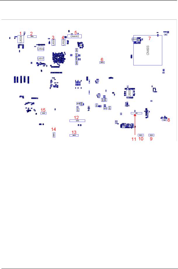
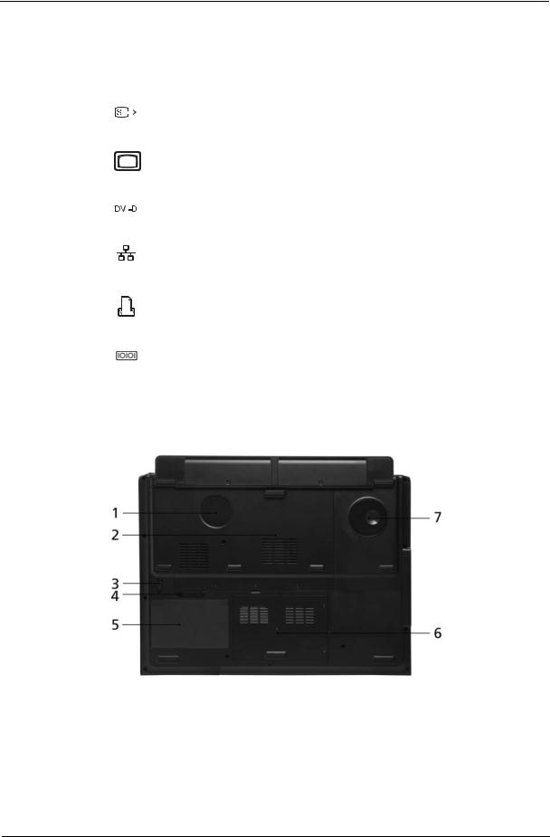
Bottom View
1 |
U504 |
LAN Transformer GSN 5009 |
9 |
CN4000 |
Touchpad Connector (Touchpad |
|
|
|
|
|
to main board) |
2 |
CN502 |
Launch Board Connector |
10 |
CN4001 6-pin Touchpad Board Connector |
|
3 |
U503 |
Video Memory |
11 |
CN504 |
Audio Board Connector |
4 |
U502 |
Video Memory |
12 |
CN506 |
DDR2 SDRAM IC |
5 |
CN4002 |
LCD Connector |
13 |
CN5001 |
Hotkey Board Connector |
6 |
CN3000 |
Hotkey Board Connector |
14 |
CN5000 Main Board to Media Board |
|
|
|
|
|
|
Connector |
7 |
CN503 |
Express Card Slot |
15 |
CN505 |
Touchpad Board Connector |
8 |
CN507 |
DDR2 SDRAM IC |
|
|
|
6 |
Chapter 1 |
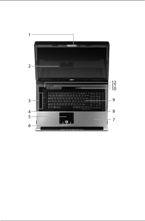
Your Acer Notebook tour
After knowing your computer features, let us show you around your new Aspire computer.
Front View
# |
Icon |
Item |
Description |
|
|
|
|
1 |
|
Built-in camera |
1.3 megapixel web camera for video |
|
|
|
communication. |
|
|
|
|
2 |
|
Display screen |
Also called Liquid-Crystal Display (LCD), |
|
|
|
displays computer output. |
|
|
|
|
3 |
|
Media/volume buttons |
For use with Acer Arcade and other mdeia |
|
|
|
playing programs. |
|
|
|
|
4/8 |
|
Microphone |
Internal microphone for sound recording. |
|
|
|
|
5 |
|
Touchpad |
Touch-sensitive pointing device which |
|
|
|
functions like a computer mouse. |
|
|
|
|
6 |
|
Click buttons (left, |
The left and right buttons function like the |
|
|
center and right) |
left and right mouse buttons; the center |
|
|
|
button serves as a 4-way scroll button. |
|
|
|
|
7 |
|
Palmrest |
Comfortable support area for your hands |
|
|
|
when you use the computer. |
|
|
|
|
9 |
|
Keyboard |
For entering data into your computer. |
|
|
|
|
Chapter 1 |
7 |
10/11 |
|
Easy-launch buttons |
Buttons for launching frequently used |
|
|
|
programs. |
|
|
|
|
12 |
|
Power button |
Turns the computer on and off. |
|
|
|
|
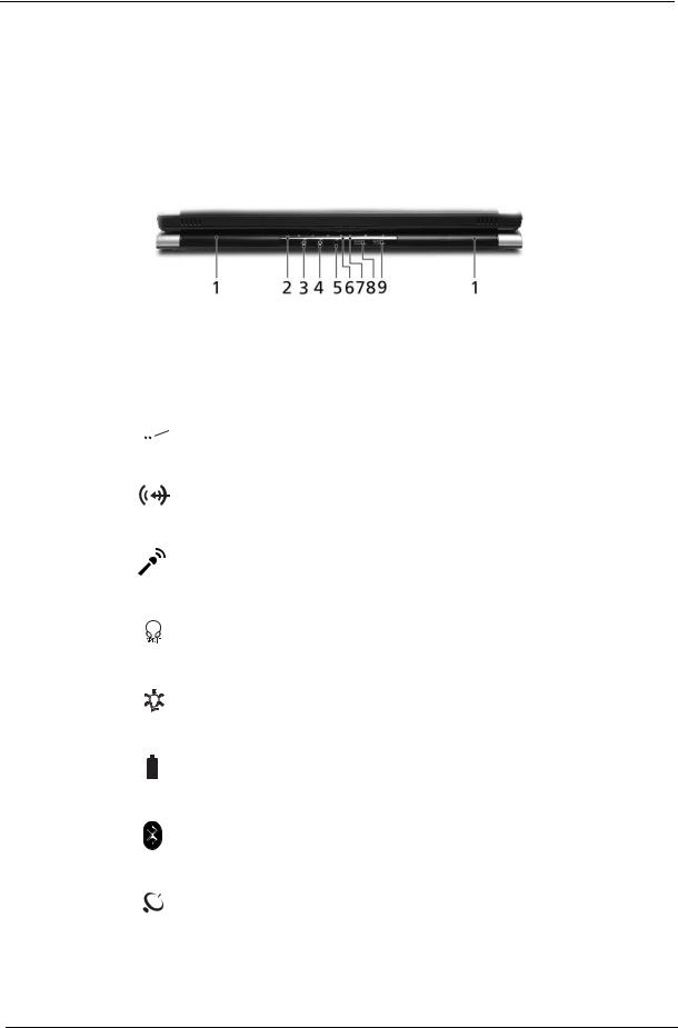
Closed Front View
# |
|
Icon |
Item |
Description |
|||||
|
|
|
|
|
|
|
|
|
|
1 |
|
|
|
|
|
|
|
Speaker |
Left and right speakers deliver stereo audio |
|
|
|
|
|
|
|
|
|
output. |
|
|
|
|
|
|
|
|
|
|
2 |
|
|
|
|
|
|
|
Infrared port/CIR |
Interfaces with infrared devices (e.g, |
|
|
|
|
|
|
|
|
receiver |
infrared printer and IR-aware computer)/ |
|
|
|
|
|
|
|
|
|
Receives signals from a remote control. |
|
|
|
|
|
|
|
|
|
|
|
|
|
|
|
|
|
|
|
|
3 |
|
|
|
|
|
|
|
Line-in jack |
Accepts audio line-in devices (e.g., audio |
|
|
|
|
|
|
|
|
|
CD player, stereo walkman). |
|
|
|
|
|
|
|
|
|
|
4 |
|
|
|
|
|
|
|
Microphone-in jack |
Accepts input from external microphones. |
|
|
|
|
|
|
|
|
|
|
5 |
|
|
|
|
|
|
|
Headphones/speaker/ |
Connects to audio line-out devices (e.g., |
|
|
|
|
|
|
|
|
line-out jack with S/ |
speakers, headphones). |
|
|
|
|
|
|
|
|
PDIF support |
|
|
|
|
|
|
|
|
|
|
|
6 |
|
|
|
|
|
|
|
Power indicator |
Indicates the computer’s power status. |
|
|
|
|
|
|
|
|
|
|
7 |
|
|
|
|
|
|
|
Battery indicator |
Indicates the computer’s battery status. |
|
|
|
|
|
|
|
|
|
|
|
|
|
|
|
|
|
|
|
|
|
|
|
|
|
|
|
|
|
|
8 |
|
|
|
|
|
|
|
Bluetooth® |
Enables/disables the Bluetooth® function. |
|
|
|
|
|
|
|
|
communication button/ |
Indicates the status of Bluetooth |
|
|
|
|
|
|
|
|
indicator |
communication. |
|
|
|
|
|
|
|
|
|
|
9 |
|
|
|
|
|
|
|
Wireless |
Enables/disables the wireless function. |
|
|
|
|
|
|
|
|
communication button/ |
Indicates the status of wireless LAN |
|
|
|
|
|
|
|
|
indicator |
communication. |
|
|
|
|
|
|
|
|
|
|
8 |
Chapter 1 |
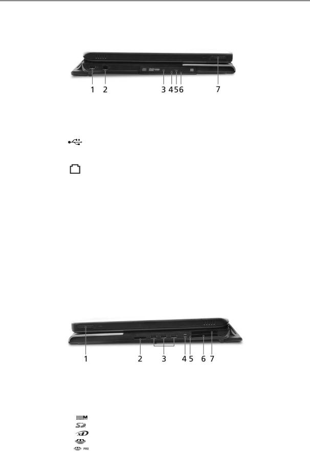
Left View
# |
Icon |
Item |
Description |
|
|
|
|
1 |
|
USB 2.0 ports |
Connects to USB 2.0 devices (e.g., USB |
|
|
|
mouse, USB camera). |
|
|
|
|
2 |
|
Modem (RJ-11) port |
Connects to a phone line. |
|
|
|
|
3 |
|
Optical drive |
Internal optical drive; accepts CDs or DVDs |
|
|
|
(slot-load or tray-load depending on |
|
|
|
model). |
|
|
|
|
4 |
|
Optical disk access |
Lights up when the optical drive is active. |
|
|
indicator |
|
|
|
|
|
5 |
|
Optical drive eject |
Ejects the optical disk from the drive. |
|
|
button |
|
|
|
|
|
6 |
|
Emergency eject hole |
Ejects the optical drive tray when the |
|
|
|
computer is turned off. |
|
|
|
|
7 |
|
Latch |
Locks and releases the lid. |
|
|
|
|
Right View
|
# |
Icon |
Item |
Description |
|
|
|
|
|
|
|
|
1 |
|
Latch |
Locks and releases the lid. |
|
|
|
|
|
|
|
|
2 |
|
5-in-1 card reader |
Accepts Secure Digital (SD), |
|
|
|
|
|
MultiMediaCard (MMC), Memory Stick |
|
|
|
|
|
(MS), Memory Stick PRO (MS PRO), xD- |
|
|
|
|
|
Picture Card (xD). |
|
|
|
|
|
|
|
|
|
|
|
|
|
Chapter 1 |
9 |
3 |
|
|
|
|
|
|
3 USB 2.0 ports |
Connect to USB 2.0 devices (e.g., USB |
|
|
|
|
|
|
|
|
mouse, USB camera). |
|
|
|
|
|
|
|
|
|
4 |
|
|
|
|
|
|
4-pin IEEE 1394 port |
Connects to IEEE 1394 devices. |
|
|
|
|
|
|
|
|
|
5 |
|
|
|
|
|
|
PC Card slot eject |
Ejects the PC Card from the slot. |
|
|
|
|
|
|
|
button |
|
|
|
|
|
|
|
|
|
|
6 |
|
|
|
|
|
|
PC Card slot |
Accepts one Type II PC Card. |
|
|
|
|
|
|
|
|
|
|
|
|
|
|
|
|
|
|
|
|
|
|
|
|
|
|
|
|
|
|
|
|
|
|
|
|
7 |
|
|
|
|
|
|
Express Card/54 slot |
Accepts and ExpressCard/34 module |
|
|
|
|
|
|
|
|
Note: ExpressCards are third generation of |
|
|
|
|
|
|
|
|
PC cards, hot-swapable and smaller than |
|
|
|
|
|
|
|
|
previous PC Cards. Designed for both |
|
|
|
|
|
|
|
|
desktop and mobile use, ExpressCards |
|
|
|
|
|
|
|
|
use either USB 2.0 or a single lane PCI |
|
|
|
|
|
|
|
|
Express technology that provides 500 |
|
|
|
|
|
|
|
|
Mbytes/sec total throughput. Formerly |
|
|
|
|
|
|
|
|
code named "NEWCARD," ExpressCards |
|
|
|
|
|
|
|
|
are 5 mm thick like Type II PC Cards, but |
|
|
|
|
|
|
|
|
do not use the same 86x54 mm footprint. |
|
|
|
|
|
|
|
|
ExpressCards come in 75x54 mm and |
|
|
|
|
|
|
|
|
75x34 mm sizes. Express Card/54 slot |
|
|
|
|
|
|
|
|
means this notebook accepts 75x54mm |
|
|
|
|
|
|
|
|
ExpressCards. |
|
|
|
|
|
|
|
|
|
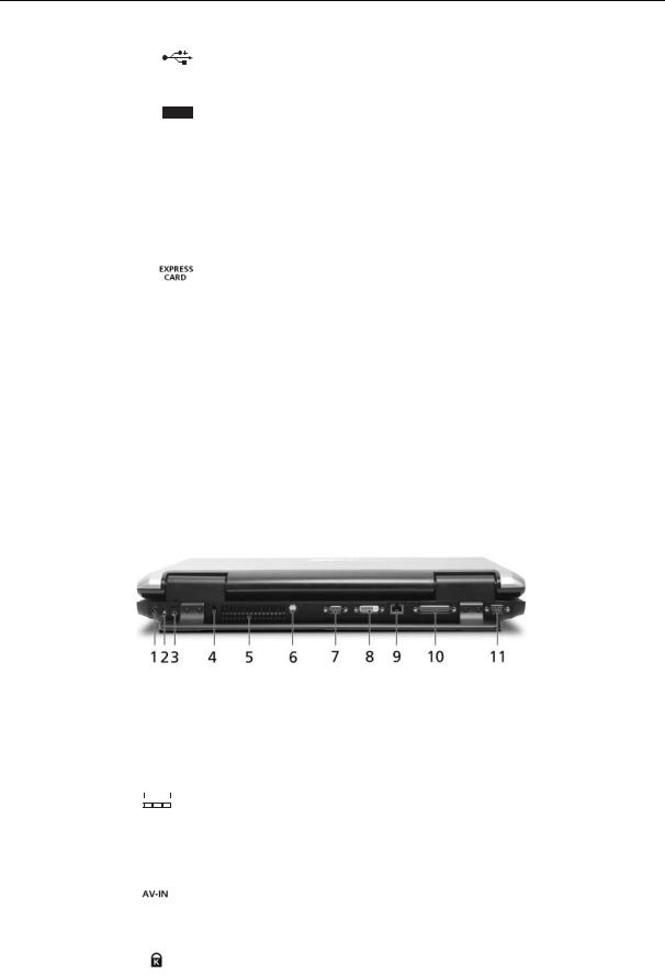
Rear view
|
# |
Icon |
Item |
Description |
|
||||||
|
|
|
|
|
|
|
|
|
|
|
|
|
1 |
|
|
|
|
|
|
|
DC-in jack |
Connects to an AC adapter. |
|
|
|
|
|
|
|
|
|
|
|
|
|
|
|
|
|
|
|
|
|
|
|
|
|
|
|
|
|
|
|
|
|
|
|
|
|
|
2 |
|
|
|
|
|
|
|
TV-in port |
Accepts input signals from analog/digital |
|
|
|
|
|
|
|
|
|
|
|
TV-tuner devices (for selected models). |
|
|
|
|
|
|
|
|
|
|
|
|
|
|
3 |
|
|
|
|
|
|
|
AV-in port |
Accepts input signals from audio/video |
|
|
|
|
|
|
|
|
|
|
|
(AV) devices (manufacturing option). |
|
|
|
|
|
|
|
|
|
|
|
|
|
|
4 |
|
|
|
|
|
|
|
Kensington lock slot |
Connects to a Kensington-compatible |
|
|
|
|
|
|
|
|
|
|
|
computer security lock. |
|
|
|
|
|
|
|
|
|
|
|
|
|
|
|
|
|
|
|
|
|
|
|
|
|
10 |
Chapter 1 |
# |
Icon |
Item |
Description |
|||||
|
|
|
|
|
|
|
|
|
5 |
|
|
|
|
|
|
Ventilation slots |
Enable the computer to stay cool, even |
|
|
|
|
|
|
|
|
after prolonged use. |
|
|
|
|
|
|
|
|
|
6 |
|
|
|
|
|
|
S-video/TV-out |
Connects to a television or display |
|
|
|
|
|
|
|
(NTSC/PAL) port |
device with S-video input. |
|
|
|
|
|
|
|
|
|
7 |
|
|
|
|
|
|
External display |
Connects to a display device (e.g., |
|
|
|
|
|
|
|
(VGA) port |
external monitor, LCD projector). |
|
|
|
|
|
|
|
|
|
8 |
|
|
|
|
|
|
DVI-D port |
Supports digital video connections. |
|
|
|
|
|
|
|
|
|
|
|
|
|
|
|
|
|
|
|
|
|
|
|
|
|
|
|
9 |
|
|
|
|
|
|
Ethernet (RJ-45) |
Connects to an Ethernet 10/100/1000- |
|
|
|
|
|
|
|
|
based network (for selected models). |
|
|
|
|
|
|
|
|
|
10 |
|
|
|
|
|
|
Parallel port |
Connects to a printer. |
|
|
|
|
|
|
|
|
|
|
|
|
|
|
|
|
|
|
|
|
|
|
|
|
|
|
|
|
|
|
|
|
|
|
|
|
|
|
|
|
|
|
|
|
|
|
|
|
|
|
|
|
|
|
|
|
|
|
|
|
|
|
|
11 |
|
|
|
|
|
|
Serial port |
Connects to a serial device. |
|
|
|
|
|
|
|
|
|
Base view
# |
Item |
Description |
|
|
|
1 |
Ventilation slots and |
Enable the computer to stay cool, even |
|
cooling fan |
after prolonged use. |
|
|
Note: Do not cover or obstruct the opening |
|
|
of the fan. |
|
|
|
Chapter 1 |
11 |
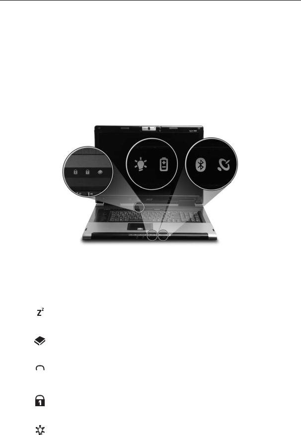
2 |
Memory compartment |
Houses the computer’s main memory. |
|
|
|
3 |
Battery lock |
Locks the battery in position. |
|
|
|
4 |
Battery release latch |
Releases the battery for removal. |
|
|
|
5 |
Battery bay |
Houses the computer’s battery pack. |
|
|
|
6 |
Hard disk bay |
Houses the computer’s hard disk (secured |
|
|
with screws) |
|
|
|
7 |
Sub woofer |
Emits low frequency sound output. |
|
|
|
Indicators
The computer has several easy-to-read status indicators.
The front panel indicators are visible even when the computer cover is closed up.
|
Icon |
Function |
Description |
|
||
|
|
|
|
|
|
|
|
|
|
|
Standby |
Indicates the computer’s standby status. |
|
|
|
|
|
|
|
|
|
|
|
|
HDD |
Indicates when the hard disc or optical |
|
|
|
|
|
|
drive is active. |
|
|
|
|
|
|
|
|
|
|
|
|
Cap lock |
Lights when Cap Lock is activated |
|
|
|
|
|
|
|
|
|
|
|
|
|
|
|
|
|
|
|
|
|
|
|
|
|
|
Num lock |
Lights when Num Lock is activated. |
|
|
|
|
|
|
|
|
|
|
|
|
Power |
Lights up when the computer is on. |
|
|
|
|
|
|
|
|
|
|
|
|
|
|
|
12 |
Chapter 1 |
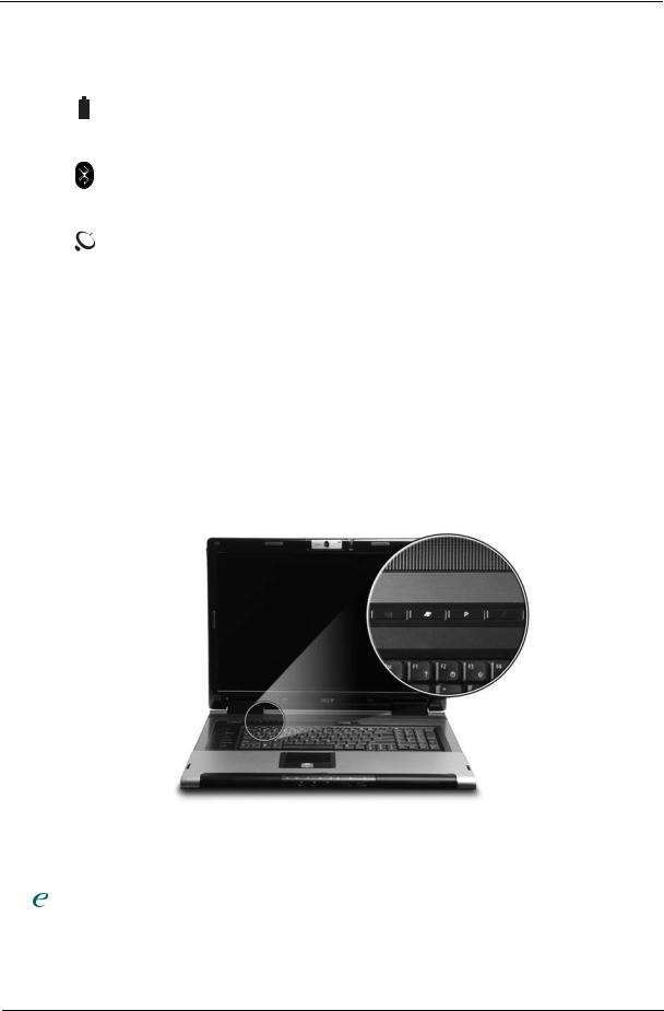
Icon |
Function |
Description |
||
|
|
|
|
|
|
|
|
Battery |
Lights up when the battery is being |
|
|
|
||
|
|
|
|
charged. |
|
|
|
|
|
|
|
|
|
|
|
|
|
Bluetooth |
Indicates the status of Bluetooth |
|
|
|
|
communication. |
|
|
|
|
|
|
|
|
Wireless LAN |
Indicates the status of wireless LAN |
|
|
|
|
communication. |
|
|
|
|
|
NOTE: 1. Charging: The light shows amber when the battery is charging. 2. Fully charged: The light shows green when in AC mode.
Easy-Launch Buttons
Located above the keyboard are four buttons. These buttons are called easy-launch buttons. They are: mail Web browser, Empowering Key “  “and one user-programmable button.
Press “  “ to run the Acer Empowering Technology. The mail and Web browser buttons are pre-set to email and Internet programs, but can be reset by users. To set the Web browser, mail and programmable buttons, run the Acer Launch Manager.
Launch key |
Default application |
|
|
|
Acer Empowering Technology (user-programmable) |
|
|
P |
User-programmable |
|
|
Web browser |
Internet browser (user-programmable) |
|
|
Email application (user-programmable) |
|
|
|
Chapter 1 |
13 |
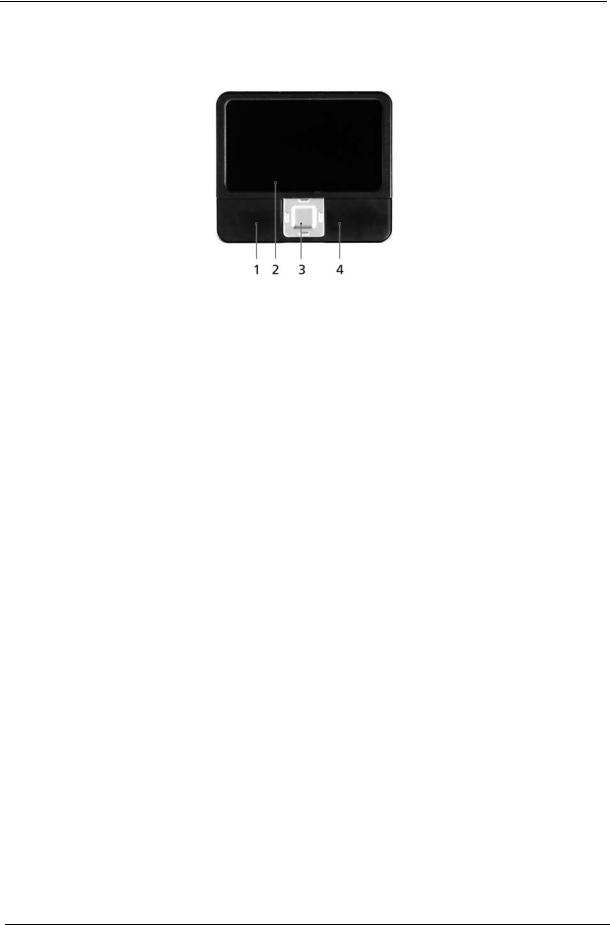
Touchpad Basics
The following teaches you how to use the touchpad:
Move your finger across the touchpad (2) to move the cursor.
Press the left (1) and right (4) buttons located beneath the touchpad to perform selection and execution functions. These two buttons are similar to the left and right buttons on a mouse. Tapping on the touchpad is the same as clicking the left button.
Use the 4-way scroll (3) button to scroll up or down and move left or right a page. This button mimics your cursor pressing on the right scroll bar of Windows applications.
Function |
Left Button (1) |
Right Button |
Main touchpad |
Center button (3) |
|
(4) |
(2) |
||||
|
|
|
|||
|
|
|
|
|
|
Execute |
Click twice |
|
Tap twice (at |
|
|
|
quickly |
|
the same speed |
|
|
|
|
|
as double- |
|
|
|
|
|
clicking the |
|
|
|
|
|
mouse button) |
|
|
|
|
|
|
|
|
Select |
Click once |
|
Tap once |
|
|
|
|
|
|
|
|
Drag |
Click and hold, |
|
Tap twice (at |
|
|
|
then use finger |
|
the same speed |
|
|
|
on the touchpad |
|
as double- |
|
|
|
to drag the |
|
clicking a |
|
|
|
cursor. |
|
mouse button); |
|
|
|
|
|
rest your finger |
|
|
|
|
|
on the touchpad |
|
|
|
|
|
on the second |
|
|
|
|
|
tap and drag |
|
|
|
|
|
the cursor. |
|
|
|
|
|
|
|
|
Access context |
|
Click once |
|
|
|
menu |
|
|
|
|
|
|
|
|
|
|
|
Scroll |
|
|
|
Click and hold to move |
|
|
|
|
|
up/down/left/right. |
|
|
|
|
|
|
NOTE: When using the touchpad, keep it - and your infers - dry and clean. The touchpad is sensitive to finger movements; hence, the lighter the touch, the better the response. Tapping too hard will not increase the touchpad’s responsiveness.
14 |
Chapter 1 |
Using the Keyboard
The keyboard has full-sized keys and an embedded keypad, separate cursor keys, two Windows keys and twelve function keys.
Lock Keys and embedded numeric keypad
The keyboard has three lock keys which you can toggle on and off.
Lock Key |
Description |
|
|
Caps Lock |
When Caps Lock is on, all alphabetic characters typed |
|
are in uppercase. |
|
|
Num lock |
When Num Lock is on, the embedded keypad is in |
<Fn>+<F11> |
numeric mode. The keys function as a calculator |
|
(complete with the arithmetic operators +, -, *, and /). |
|
Use this mode when you need to do a lot of numeric |
|
data entry. A better solution would be to connect an |
|
external keypad. |
|
|
Scroll lock |
When Scroll Lock is on, the screen moves one line up |
<Fn>+<F12> |
or down when you press the up or down arrow keys |
|
respectively. Scroll Lock does not work with some |
|
applications. |
|
|
The embedded numeric keypad functions like a desktop numeric keypad. It is indicated by small characters located on the upper right corner of the keycaps. To simplify the keyboard legend, cursor-control key symbols are not printed on the keys.
Desired Access |
Num Lock On |
Num Lock Off |
|
|
|
Number keys on embedded |
Type numbers in a normal |
|
keypad |
manner. |
|
|
|
|
Cursor-control keys on |
Hold <Shift> while using |
Hold <Fn> while using |
embedded keypad |
cursor-control keys. |
cursor-control keys. |
|
|
|
Main keyboard keys |
Hold <Fn> while typing |
Type the letters in a normal |
|
letters on embedded |
manner. |
|
keypad. |
|
|
|
|
Windows Keys
The keyboard has two keys that perform Windows-specific functions.
Chapter 1 |
15 |
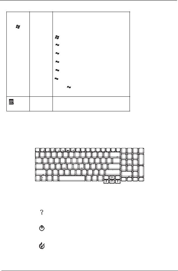
Key |
Icon |
Description |
|
|
|
Windows key |
|
Pressed alone, this key has the same effect as |
|
|
clicking on the Windows Start button; it launches the |
|
|
Start menu. It can also be used with other keys to |
|
|
provide a variety of function: |
+ <Tab> Activates next taskbar button.
 + <E> Opens the My Computer window
 + <F1> Opens Help and Support.
 + <F> Opens the Find: All Files dialog box.
 + <R> Opens the Run dialog box.
 + M Minimizes all windows.
<Shift>+  + <M> Undoes the minimize all windows action.
|
This key has the same effect as clicking the right |
|
Applicati |
mouse button; it opens the application’s context |
|
menu. |
||
on key |
||
|
Hot Keys
The computer employs hotkeys or key combinations to access most of the computer’s controls like sreen brightness, volume output and the BIOS utility.
To activate hot keys, press and hold the <Fn> key before pressing the other key in the hotkey combination.
Hot Key |
Icon |
Function |
Description |
|
|
|
|
<Fn>+<F1> |
|
Hot key help |
Displays help on hot keys. |
|
|
|
|
<Fn>+<F2> |
|
Acer eSetting |
Launches the Acer eSettings in Acer eManager. |
|
|
|
|
<Fn>+<F3> |
|
Acer |
Launches the Acer ePowerManagement in Acer |
|
|
ePowerManagement |
Empowering Technology. See “Acer Empowering |
|
|
|
Technology” on page 19. |
|
|
|
|
16 |
Chapter 1 |
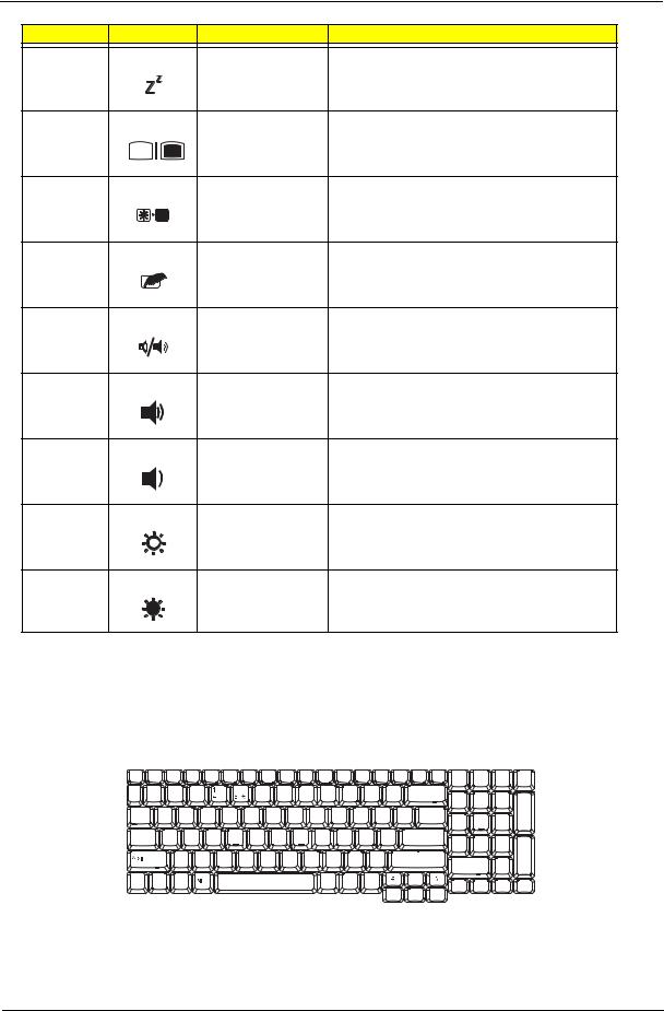
Hot Key |
Icon |
Function |
Description |
<Fn>+<F4> |
|
Sleep |
Puts the computer in Sleep mode. |
<Fn>+<F5> |
|
Display toggle |
Switches display output between the display screen, |
|
|
|
external monitor (if connected) and both. |
<Fn>+<F6> |
|
Screen blank |
Turns the display screen backlight off to save power. |
|
|
|
Press any key to return. |
<Fn>+<F7> |
|
Touchpad toggle |
Turns the internal touchpad on and off. |
<Fn>+<F8> |
|
Speaker toggle |
Turns the speakers on and off. |
<Fn>+<w> |
|
Volume up |
Increases the speaker volume. |
<Fn>+<y> |
|
Volume down |
Decreases the speaker volume. |
<Fn>+<-x> |
|
Brightness up |
Increases the screen brightness. |
<Fn>+<z> |
|
Brightness down |
Decreases the screen brightness |
Special Key
You can locate the Euro symbol and US dollar sign at the upper-center and/or bottom-right of your keyboard. To type:
The Euro symbol
1. Open a text editor or word processor.
Chapter 1 |
17 |

2.Either directly press the < > symbol at the bottom-right of the keyboard, or hold <Alt Gr> and then press the<5> symbol at the upper-center of the keyboard.
NOTE: Some fonts and software do not support the Euro symbol. Please refer to www.microsoft.com/ typography/faq/faq12.htm for more information.
The US dollar sign
1.Open a text editor or word processor.
2.Either directly press the < > key at the bottom-right of the keyboard, or hold <Shift> and then press the <4> key at the upper-center of the keyboard.
NOTE: This function varies by the operating system version.
18 |
Chapter 1 |

Acer Empowering Technology
Acer’s innovative Empowering Technology makes it easy for you to access frequently used functions and manage your new Acer notebook. It features the following handy utilities:
Acer eNet Management hooks up to location-based networks intelligently. Acer ePower Management extends battery power via versatile usage profiles.
Acer ePresentation Management connects to a projector and adjusts display settings conveniently. Acer eDataSecurity Management protects data with passwords and advanced encryption algorithms. Acer eLock Management limits access to external storage media.
Acer eRecovery Management backs up and recovers data flexibly, reliably and completely. Acer eSettings Management accesses system information and adjusts settings easily.
Acer ePerformance Management improves system performance by optimizing disk space, memory and registry settings.
For more information, press the <  > key to launch the Empowering Technology menu, then click on the appropriate utility and select the Help or Tutorial function.
Empowering Technology password
Before using Acer eLock Management and Acer eRecovery Management, you must initalize the Empowering Technology password. Right-click on the Empowering Technology toolbard and select “Password Setup” to do so. If you do not initialize the Empowering Technology password, you will be prompted to do so when running Acer eLock Management or Acer eRecovery Management for the first time.
Acer eNet Management
Acer eNet Management helps you to quickly and easily connect to both wired and wireless networks in a variety of locations. To access this utility, either click on the “Acer eNet Management” icon on your netebook, or start the program from the Start menu. You also have the option to set Acer eNet Management to start automatically when you boot up your PC.
Acer eNet Management automatically detects the best settings for a new location, while offering you the freedom to manually adjust the settings to match your needs.
Chapter 1 |
19 |
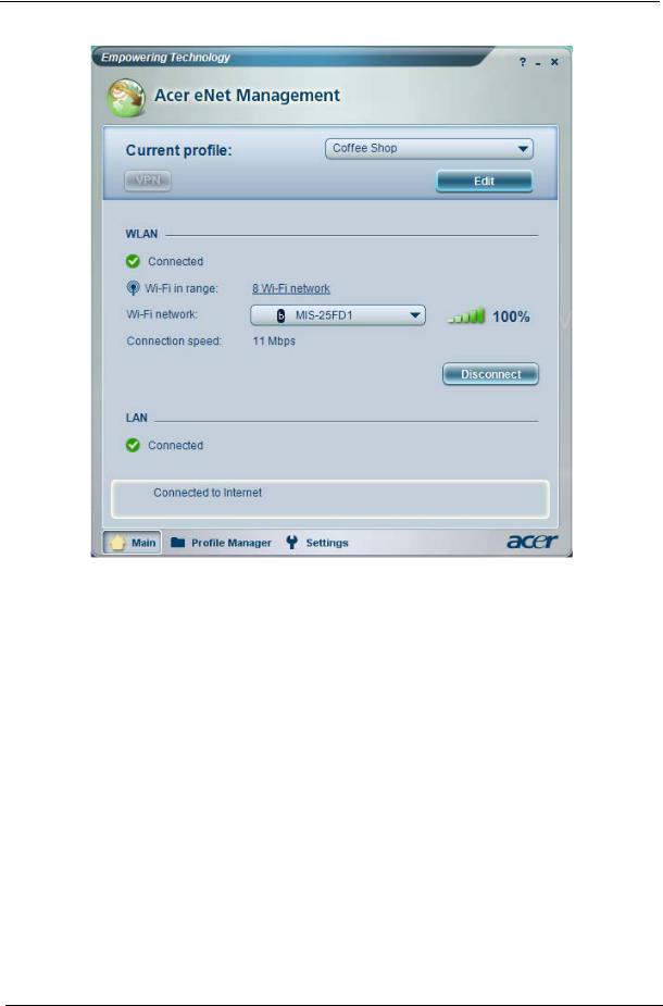
Acer eNet Management can save network settings for a location to a profile, and automatically switch to the appropriate profile when you move from one location to another. Settings stored include network connection settings (IP and DNS settings, wireless AP details, etc.), as well as default printer settings.
Security and safety concerns mean that Acer eNet Management does not store username and password information.
20 |
Chapter 1 |
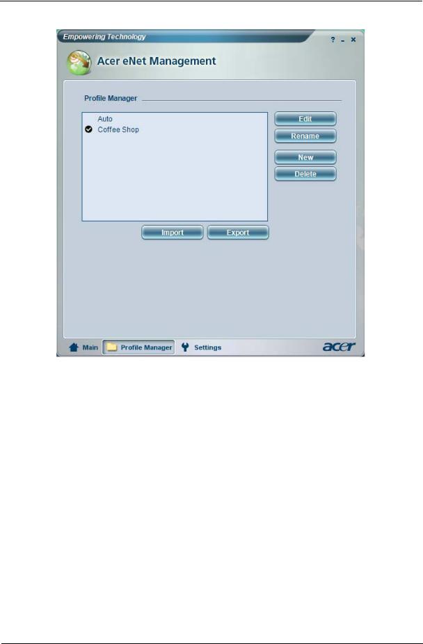
Acer ePower Management 
Acer ePower Management features a straightforward user interface. To launch it, select Acer ePower Management from the Empowering Technology interface.
AC Mode (Adapter mode)
The default setting is “Maximum Performance.” You can adjust CPU speed, LCD brightness and other settings, or click on buttons to turn the following functions on/off: Wireless LAN, Bluetooth, CardBus, FireWire (1394), Wired LAN and Optical Device if supported.
DC Mode (Battery mode)
There are four pre-defined profiles - Entertainment, Presentation, Word Processing, and Battery Life. You can also define up to three of your own.
To create new power profile
1.Change power settings as desired.
2.Click “Save as...” to save to a new power profile.
3.Name the newly created profile.
4.Select whether this profile is for Adapter or Battery mode, then click OK.
5.The new profile will appear in the profile list.
Chapter 1 |
21 |
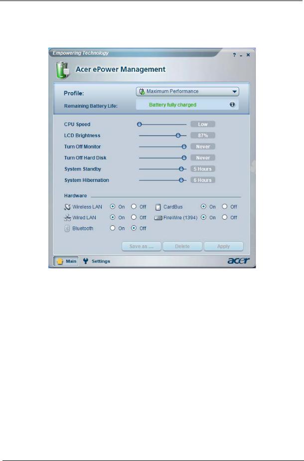
Battery status
For real-time battery life estimates based on current usage, referto the panel on the lower left-hand side of the window.
For additional options, click “Settings” to:
Set alarms.
Re-load factory defaults.
Select what actions will be taken when the cover is closed or the power button is pressed. View information about Acer ePower Management.
22 |
Chapter 1 |
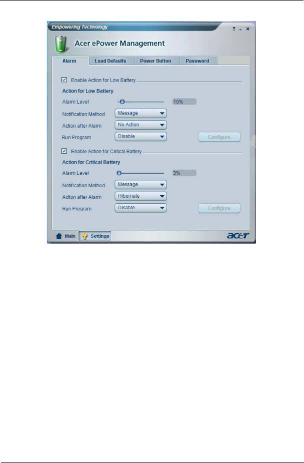
Acer ePresentation Management
Acer ePresentation Management lets you project your computer’s display to an external device or project using the hot key: Fn + F5. If auto-detection hardware is implemented in the system, your system display will be automatically switched out when an external display is connected to the system.
Chapter 1 |
23 |
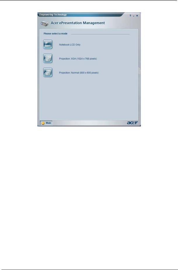
Acer eDataSecurity Management 
Acer eDataSecurity Management is handy file encryption utility that protexts your files from being accessed by unauthorized persons. It is conveniently integrated with Windows explorer as a shell extension for quick and easy data encryption/decryption and also supports on-the-fly file encryption for MSN Messager and Microsoft Outlook.
The Acer eDataSecurity Management setup wizard will prompt you for a suvervisor password and default encryption. This encryption will be used to encrypt files by default, or you can choose to enter your won filespecific password when encrypting a file.
NOTE: The password used encrypt a file is the unique key that the system needs to decrypt it. If you lose the password, the supervisor password is the only other key capable of decrypting the file. If you lose both passwords, there will be no way to decrypt your encryped file! Be sure to safeguard all related passwords!
24 |
Chapter 1 |
Loading...