


Acer ASPIRE ONE D255 User Manual

Aspire One D255 Series
Service Guide
Service guide files and updates are available
on the ACER/CSD web; for more information,
please refer to http://csd.acer.com.tw
PRINTED IN TAIWAN

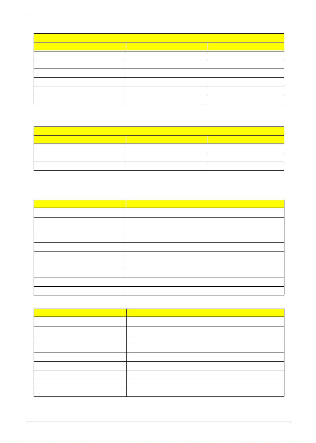
Revision History
Please refer to the table below for the updates made to this service guide.
Date Chapter Updates
II

Copyright
Copyright © 2010 by Acer Incorporated. All rights reserved. No part of this publication may be reproduced,
transmitted, transcribed, stored in a retrieval system, or translated into any language or computer language, in
any form or by any means, electronic, mechanical, magnetic, optical, chemical, manual or otherwise, without
the prior written permission of Acer Incorporated.
Disclaimer
The information in this guide is subject to change without notice.
Acer Incorporated makes no representations or warranties, either expressed or implied, with respect to the
contents hereof and specifically disclaims any warranties of merchantability or fitness for any particular
purpose. Any Acer Incorporated software described in this manual is sold or licensed "as is". Should the
programs prove defective following their purchase, the buyer (and not Acer Incorporated, its distributor, or its
dealer) assumes the entire cost of all necessary servicing, repair, and any incidental or consequential
damages resulting from any defect in the software.
Acer is a registered trademark of Acer Corporation.
Intel is a registered trademark of Intel Corporation.
Other brand and product names are trademarks and/or registered trademarks of their respective holders.
III
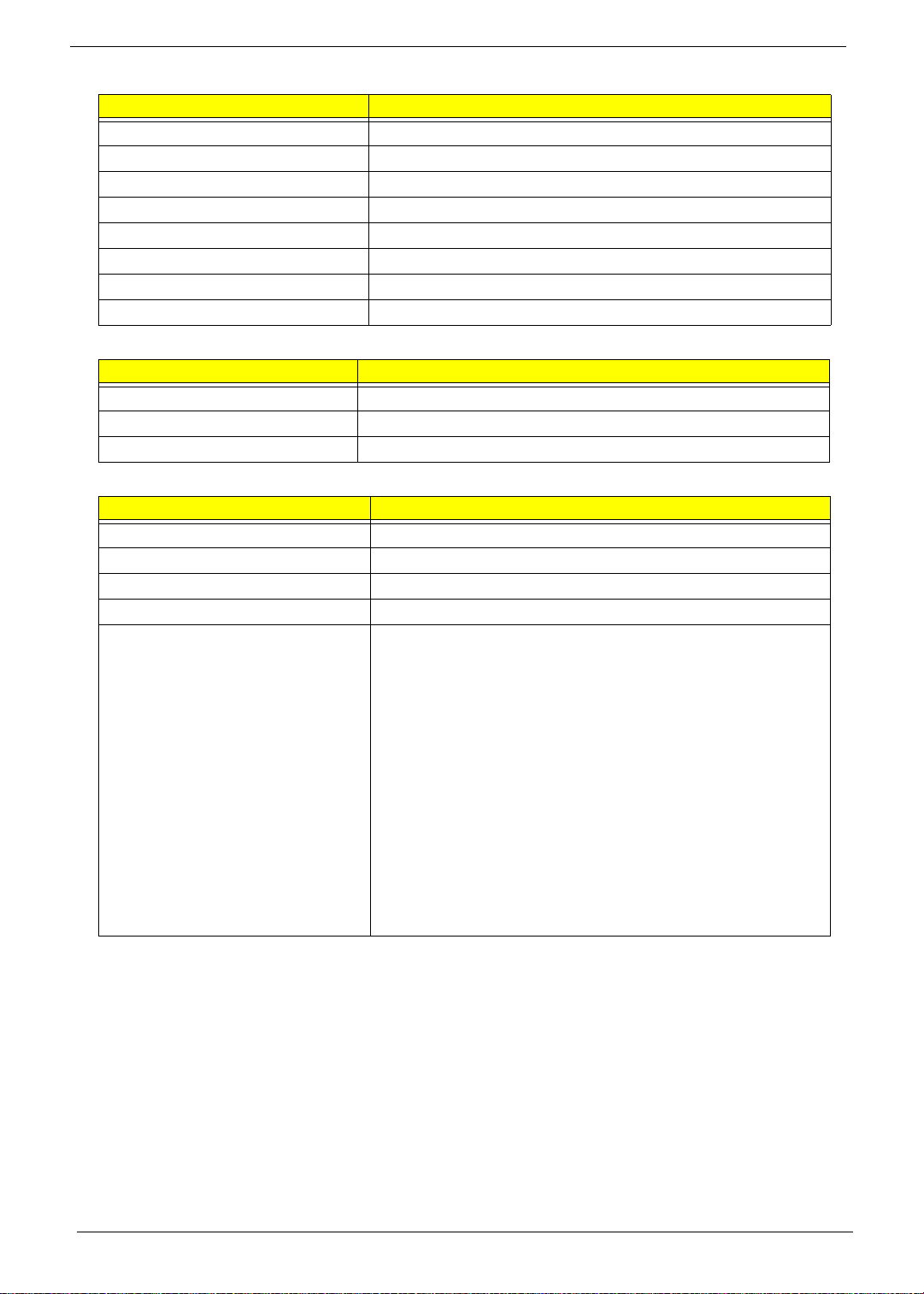
Conventions
The following conventions are used in this manual:
SCREEN MESSAGES Denotes actual messages that appear
on screen.
NOTE Gives bits and pieces of additional
information related to the current
topic.
WARNING Alerts you to any damage that might
result from doing or not doing specific
actions.
CAUTION Gives precautionary measures to
avoid possible hardware or software
problems.
IMPORTANT Reminds you to do specific actions
relevant to the accomplishment of
procedures.
NOTE: This symbol where placed in the Service Guide designates a component that should be
recycled according to the local regulations.
IV

Preface
Before using this information and the product it supports, please read the following general information.
1. This Service Guide provides you with all technical information relating to the BASIC CONFIGURATION
decided for Acer's "global" product offering. To better fit local market requirements and enhance product
competitiveness, your regional office MAY have decided to extend the functionality of a machine (e.g.
add-on card, modem, or extra memory capability). These LOCALIZED FEATURES will NOT be covered
in this generic service guide. In such cases, please contact your regional offices or the responsible
personnel/channel to provide you with further technical details.
2. Please note WHEN ORDERING FRU PARTS, that you should check the most up-to-date information
available on your regional web or channel. If, for whatever reason, a part number change is made, it will
not be noted in the printed Service Guide. For ACER-AUTHORIZED SERVICE PROVIDERS, your Acer
office may have a DIFFERENT part number code to those given in the FRU list of this printed Service
Guide. You MUST use the list provided by your regional Acer office to order FRU parts for repair and
service of customer machines.
V

VI

Table of Contents
System Specifications 1
Features . . . . . . . . . . . . . . . . . . . . . . . . . . . . . . . . . . . . . . . . . . . . . . . . . . . . . . . . . . . .1
System Block Diagram . . . . . . . . . . . . . . . . . . . . . . . . . . . . . . . . . . . . . . . . . . . . . . . .5
DDR2 . . . . . . . . . . . . . . . . . . . . . . . . . . . . . . . . . . . . . . . . . . . . . . . . . . . . . . . . . .5
DDR3 . . . . . . . . . . . . . . . . . . . . . . . . . . . . . . . . . . . . . . . . . . . . . . . . . . . . . . . . . .6
Your Notebook Tour . . . . . . . . . . . . . . . . . . . . . . . . . . . . . . . . . . . . . . . . . . . . . . . . . . .7
Top View . . . . . . . . . . . . . . . . . . . . . . . . . . . . . . . . . . . . . . . . . . . . . . . . . . . . . . . .7
Closed Front View . . . . . . . . . . . . . . . . . . . . . . . . . . . . . . . . . . . . . . . . . . . . . . . . .8
Rear View . . . . . . . . . . . . . . . . . . . . . . . . . . . . . . . . . . . . . . . . . . . . . . . . . . . . . . .8
Left View . . . . . . . . . . . . . . . . . . . . . . . . . . . . . . . . . . . . . . . . . . . . . . . . . . . . . . . .8
Right View . . . . . . . . . . . . . . . . . . . . . . . . . . . . . . . . . . . . . . . . . . . . . . . . . . . . . . .9
Bottom View . . . . . . . . . . . . . . . . . . . . . . . . . . . . . . . . . . . . . . . . . . . . . . . . . . . .10
Touchpad Basics . . . . . . . . . . . . . . . . . . . . . . . . . . . . . . . . . . . . . . . . . . . . . . . .11
Using the Keyboard . . . . . . . . . . . . . . . . . . . . . . . . . . . . . . . . . . . . . . . . . . . . . . . . . .12
Lock Keys and Embedded Numeric Keypad . . . . . . . . . . . . . . . . . . . . . . . . . . .12
Windows Keys . . . . . . . . . . . . . . . . . . . . . . . . . . . . . . . . . . . . . . . . . . . . . . . . . .13
Hot Keys . . . . . . . . . . . . . . . . . . . . . . . . . . . . . . . . . . . . . . . . . . . . . . . . . . . . . . .14
Using the communication key . . . . . . . . . . . . . . . . . . . . . . . . . . . . . . . . . . . . . . .15
Special Key . . . . . . . . . . . . . . . . . . . . . . . . . . . . . . . . . . . . . . . . . . . . . . . . . . . . .15
Hardware Specifications and Configurations . . . . . . . . . . . . . . . . . . . . . . . . . . . . . . .16
System Utilities 27
BIOS Setup Utility . . . . . . . . . . . . . . . . . . . . . . . . . . . . . . . . . . . . . . . . . . . . . . . . . . . .27
Navigating the BIOS Utility . . . . . . . . . . . . . . . . . . . . . . . . . . . . . . . . . . . . . . . . .27
Information . . . . . . . . . . . . . . . . . . . . . . . . . . . . . . . . . . . . . . . . . . . . . . . . . . . . .28
Main . . . . . . . . . . . . . . . . . . . . . . . . . . . . . . . . . . . . . . . . . . . . . . . . . . . . . . . . . .29
Security . . . . . . . . . . . . . . . . . . . . . . . . . . . . . . . . . . . . . . . . . . . . . . . . . . . . . . . .30
Boot . . . . . . . . . . . . . . . . . . . . . . . . . . . . . . . . . . . . . . . . . . . . . . . . . . . . . . . . . . .33
Exit . . . . . . . . . . . . . . . . . . . . . . . . . . . . . . . . . . . . . . . . . . . . . . . . . . . . . . . . . . .34
BIOS Flash Utility . . . . . . . . . . . . . . . . . . . . . . . . . . . . . . . . . . . . . . . . . . . . . . . . . . . .35
DOS Flash Utility . . . . . . . . . . . . . . . . . . . . . . . . . . . . . . . . . . . . . . . . . . . . . . . . .36
WinFlash Utility . . . . . . . . . . . . . . . . . . . . . . . . . . . . . . . . . . . . . . . . . . . . . . . . . .38
Remove HDD/BIOS Password Utilities . . . . . . . . . . . . . . . . . . . . . . . . . . . . . . . . . . . .39
Miscellaneous Utilities . . . . . . . . . . . . . . . . . . . . . . . . . . . . . . . . . . . . . . . . . . . . .41
Machine Disassembly and Replacement 45
Disassembly Requirements . . . . . . . . . . . . . . . . . . . . . . . . . . . . . . . . . . . . . . . . . . . .45
General Information . . . . . . . . . . . . . . . . . . . . . . . . . . . . . . . . . . . . . . . . . . . . . . . . . .46
Pre-disassembly Instructions . . . . . . . . . . . . . . . . . . . . . . . . . . . . . . . . . . . . . . .46
Disassembly Process . . . . . . . . . . . . . . . . . . . . . . . . . . . . . . . . . . . . . . . . . . . . .46
External Module Disassembly Process . . . . . . . . . . . . . . . . . . . . . . . . . . . . . . . . . . .47
External Modules Disassembly Flowchart . . . . . . . . . . . . . . . . . . . . . . . . . . . . .47
Removing the Battery Pack . . . . . . . . . . . . . . . . . . . . . . . . . . . . . . . . . . . . . . . .48
Removing the SD Dummy Card . . . . . . . . . . . . . . . . . . . . . . . . . . . . . . . . . . . . .49
Removing the 3G Card . . . . . . . . . . . . . . . . . . . . . . . . . . . . . . . . . . . . . . . . . . . .50
Removing the Keyboard . . . . . . . . . . . . . . . . . . . . . . . . . . . . . . . . . . . . . . . . . . .51
Removing the Lower Door . . . . . . . . . . . . . . . . . . . . . . . . . . . . . . . . . . . . . . . . .53
Removing the DIMM Module . . . . . . . . . . . . . . . . . . . . . . . . . . . . . . . . . . . . . . .54
Removing the HDD Module . . . . . . . . . . . . . . . . . . . . . . . . . . . . . . . . . . . . . . . .55
Removing the 3G Module . . . . . . . . . . . . . . . . . . . . . . . . . . . . . . . . . . . . . . . . . .57
Removing the WLAN Module . . . . . . . . . . . . . . . . . . . . . . . . . . . . . . . . . . . . . . .58
Main Unit Disassembly Process . . . . . . . . . . . . . . . . . . . . . . . . . . . . . . . . . . . . . . . . .60
Main Unit Disassembly Flowchart . . . . . . . . . . . . . . . . . . . . . . . . . . . . . . . . . . . .60
Removing the Upper Cover . . . . . . . . . . . . . . . . . . . . . . . . . . . . . . . . . . . . . . . .61
VII

Table of Contents
Removing the Button Board . . . . . . . . . . . . . . . . . . . . . . . . . . . . . . . . . . . . . . . .65
Removing the LED Board . . . . . . . . . . . . . . . . . . . . . . . . . . . . . . . . . . . . . . . . . .67
Removing the Bluetooth Module . . . . . . . . . . . . . . . . . . . . . . . . . . . . . . . . . . . . .68
Removing the RTC Battery . . . . . . . . . . . . . . . . . . . . . . . . . . . . . . . . . . . . . . . . .69
Removing the Speaker Module . . . . . . . . . . . . . . . . . . . . . . . . . . . . . . . . . . . . . .70
Removing the Mainboard . . . . . . . . . . . . . . . . . . . . . . . . . . . . . . . . . . . . . . . . . .72
Removing the Thermal Module . . . . . . . . . . . . . . . . . . . . . . . . . . . . . . . . . . . . . .76
Removing the LCD Module . . . . . . . . . . . . . . . . . . . . . . . . . . . . . . . . . . . . . . . . .78
LCD Module Disassembly Process . . . . . . . . . . . . . . . . . . . . . . . . . . . . . . . . . . . . . .81
LCD Module Disassembly Flowchart . . . . . . . . . . . . . . . . . . . . . . . . . . . . . . . . .81
Removing the LCD Bezel . . . . . . . . . . . . . . . . . . . . . . . . . . . . . . . . . . . . . . . . . .82
Removing the Camera Module . . . . . . . . . . . . . . . . . . . . . . . . . . . . . . . . . . . . . .83
Removing the LCD Panel . . . . . . . . . . . . . . . . . . . . . . . . . . . . . . . . . . . . . . . . . .84
Removing the Microphone Module . . . . . . . . . . . . . . . . . . . . . . . . . . . . . . . . . . .87
Removing the LCD Brackets . . . . . . . . . . . . . . . . . . . . . . . . . . . . . . . . . . . . . . . .88
Removing the 3G and WLAN Antennas . . . . . . . . . . . . . . . . . . . . . . . . . . . . . .89
LCD Module Reassembly Procedure . . . . . . . . . . . . . . . . . . . . . . . . . . . . . . . . . . . . .91
Replacing the 3G and WLAN Antennas . . . . . . . . . . . . . . . . . . . . . . . . . . . . . . .91
Replacing the LCD Brackets . . . . . . . . . . . . . . . . . . . . . . . . . . . . . . . . . . . . . . . .93
Replacing Microphone Module . . . . . . . . . . . . . . . . . . . . . . . . . . . . . . . . . . . . . .94
Replacing the LVDS Cable . . . . . . . . . . . . . . . . . . . . . . . . . . . . . . . . . . . . . . . . .95
Replacing the CCD Module . . . . . . . . . . . . . . . . . . . . . . . . . . . . . . . . . . . . . . . .97
Replacing the LCD Bezel . . . . . . . . . . . . . . . . . . . . . . . . . . . . . . . . . . . . . . . . . .97
Main Module Reassembly Procedure . . . . . . . . . . . . . . . . . . . . . . . . . . . . . . . . . . . . .99
Replacing the LCD Module . . . . . . . . . . . . . . . . . . . . . . . . . . . . . . . . . . . . . . . . .99
Replacing the Thermal Module . . . . . . . . . . . . . . . . . . . . . . . . . . . . . . . . . . . . .102
Replacing the Mainboard . . . . . . . . . . . . . . . . . . . . . . . . . . . . . . . . . . . . . . . . .103
Replacing the Speakers . . . . . . . . . . . . . . . . . . . . . . . . . . . . . . . . . . . . . . . . . .107
Replacing the RTC Battery . . . . . . . . . . . . . . . . . . . . . . . . . . . . . . . . . . . . . . . .108
Replacing the Bluetooth Module . . . . . . . . . . . . . . . . . . . . . . . . . . . . . . . . . . . .108
Replacing the LED Board . . . . . . . . . . . . . . . . . . . . . . . . . . . . . . . . . . . . . . . . .109
Replacing the Button Board . . . . . . . . . . . . . . . . . . . . . . . . . . . . . . . . . . . . . . .110
Replacing the Upper Cover . . . . . . . . . . . . . . . . . . . . . . . . . . . . . . . . . . . . . . . .112
Replacing the WLAN Module . . . . . . . . . . . . . . . . . . . . . . . . . . . . . . . . . . . . . .115
Replacing the 3G Module . . . . . . . . . . . . . . . . . . . . . . . . . . . . . . . . . . . . . . . . .116
Replacing the HDD Module . . . . . . . . . . . . . . . . . . . . . . . . . . . . . . . . . . . . . . .117
Replacing the DIMM Module . . . . . . . . . . . . . . . . . . . . . . . . . . . . . . . . . . . . . . .119
Replacing the Lower Cover . . . . . . . . . . . . . . . . . . . . . . . . . . . . . . . . . . . . . . . .119
Replacing the Keyboard . . . . . . . . . . . . . . . . . . . . . . . . . . . . . . . . . . . . . . . . . .120
Replacing the 3G Card . . . . . . . . . . . . . . . . . . . . . . . . . . . . . . . . . . . . . . . . . . .121
Replacing the SD Dummy Card . . . . . . . . . . . . . . . . . . . . . . . . . . . . . . . . . . . .122
Replacing the Battery . . . . . . . . . . . . . . . . . . . . . . . . . . . . . . . . . . . . . . . . . . . .122
Troubleshooting 125
Common Problems . . . . . . . . . . . . . . . . . . . . . . . . . . . . . . . . . . . . . . . . . . . . . . . . . .125
Power On Issue . . . . . . . . . . . . . . . . . . . . . . . . . . . . . . . . . . . . . . . . . . . . . . . .126
No Display Issue . . . . . . . . . . . . . . . . . . . . . . . . . . . . . . . . . . . . . . . . . . . . . . . .127
Random Loss of BIOS Settings . . . . . . . . . . . . . . . . . . . . . . . . . . . . . . . . . . . .128
LCD Failure . . . . . . . . . . . . . . . . . . . . . . . . . . . . . . . . . . . . . . . . . . . . . . . . . . . .129
Built-In Keyboard Failure . . . . . . . . . . . . . . . . . . . . . . . . . . . . . . . . . . . . . . . . .129
Touch Pad Failure . . . . . . . . . . . . . . . . . . . . . . . . . . . . . . . . . . . . . . . . . . . . . . .130
Internal Speaker Failure . . . . . . . . . . . . . . . . . . . . . . . . . . . . . . . . . . . . . . . . . .130
Internal Microphone Failure . . . . . . . . . . . . . . . . . . . . . . . . . . . . . . . . . . . . . . .132
HDD Not Operating Correctly . . . . . . . . . . . . . . . . . . . . . . . . . . . . . . . . . . . . . .133
USB Failure . . . . . . . . . . . . . . . . . . . . . . . . . . . . . . . . . . . . . . . . . . . . . . . . . . . .134
VIII

Table of Contents
Wireless Function Failure . . . . . . . . . . . . . . . . . . . . . . . . . . . . . . . . . . . . . . . . .134
3G Function Failure . . . . . . . . . . . . . . . . . . . . . . . . . . . . . . . . . . . . . . . . . . . . .135
Cosmetic Failure . . . . . . . . . . . . . . . . . . . . . . . . . . . . . . . . . . . . . . . . . . . . . . . .136
Thermal Unit Failure . . . . . . . . . . . . . . . . . . . . . . . . . . . . . . . . . . . . . . . . . . . . .137
External Mouse Failure . . . . . . . . . . . . . . . . . . . . . . . . . . . . . . . . . . . . . . . . . . .137
Other Failures . . . . . . . . . . . . . . . . . . . . . . . . . . . . . . . . . . . . . . . . . . . . . . . . . .138
Intermittent Problems . . . . . . . . . . . . . . . . . . . . . . . . . . . . . . . . . . . . . . . . . . . . . . . .139
Undetermined Problems . . . . . . . . . . . . . . . . . . . . . . . . . . . . . . . . . . . . . . . . . . . . . .139
Post Codes . . . . . . . . . . . . . . . . . . . . . . . . . . . . . . . . . . . . . . . . . . . . . . . . . . . . . . . .140
Sec: . . . . . . . . . . . . . . . . . . . . . . . . . . . . . . . . . . . . . . . . . . . . . . . . . . . . . . . . . .140
Memory: . . . . . . . . . . . . . . . . . . . . . . . . . . . . . . . . . . . . . . . . . . . . . . . . . . . . . .140
BDS & Specific action: . . . . . . . . . . . . . . . . . . . . . . . . . . . . . . . . . . . . . . . . . . .141
Each PEIM entry point used in 80_PORT . . . . . . . . . . . . . . . . . . . . . . . . . . . . .142
Each Driver entry point used in 80_PORT . . . . . . . . . . . . . . . . . . . . . . . . . . . .142
Each SmmDriver entry point used in 80_PORT . . . . . . . . . . . . . . . . . . . . . . . .145
Jumper and Connector Locations 147
Mainboard Bottom View (DDR3 Model) . . . . . . . . . . . . . . . . . . . . . . . . . . . . . .148
Clearing Password Check and BIOS Recovery . . . . . . . . . . . . . . . . . . . . . . . . . . . .149
Clearing Password Check . . . . . . . . . . . . . . . . . . . . . . . . . . . . . . . . . . . . . . . . .149
BIOS Recovery by Crisis Disk . . . . . . . . . . . . . . . . . . . . . . . . . . . . . . . . . . . . .150
FRU (Field Replaceable Unit) List 151
Exploded Diagrams . . . . . . . . . . . . . . . . . . . . . . . . . . . . . . . . . . . . . . . . . . . . . . . . .152
Main Assembly . . . . . . . . . . . . . . . . . . . . . . . . . . . . . . . . . . . . . . . . . . . . . . . . .152
Logic Lower Assembly . . . . . . . . . . . . . . . . . . . . . . . . . . . . . . . . . . . . . . . . . . .153
Logic Upper Assembly . . . . . . . . . . . . . . . . . . . . . . . . . . . . . . . . . . . . . . . . . . .154
LCD Assembly . . . . . . . . . . . . . . . . . . . . . . . . . . . . . . . . . . . . . . . . . . . . . . . . .155
Aspire D255 FRU List . . . . . . . . . . . . . . . . . . . . . . . . . . . . . . . . . . . . . . . . . . . .156
Screw List . . . . . . . . . . . . . . . . . . . . . . . . . . . . . . . . . . . . . . . . . . . . . . . . . . . . .176
Model Definition and Configuration 177
Aspire D255 . . . . . . . . . . . . . . . . . . . . . . . . . . . . . . . . . . . . . . . . . . . . . . . . . . .177
Test Compatible Components 255
Online Support Information 259
Index 261
IX

Table of Contents
X

System Specifications
Features
Below is a brief summary of the computer’s many features:
Operating system
• Genuine Windows® 7 Home Basic 32-bit (China only)
• Genuine Windows® 7 Starter 32-bit
• Genuine Windows® XP Home (Service Pack 3)
CPU and chipset
• Intel® Atom™ processor N550 (1 MB L2 cache, 1.50 GHz, DDR3 667 MHz, 8.5 W) (for model with
DDR3 support only)
• Intel® Atom™ processor N450 (512 KB L2 cache, 1.66 GHz, DDR2 667 MHz, 5.5 W) (for model
with DDR2 support only)
• Mobile Intel® NM10 Express Chipset
Chapter 1
Memory
• Single-channel DDR3 SDRAM support with one soDIMM module (fo r model with Intel® Atom™
• Single-channel DDR2 SDRAM support with one soDIMM module (fo r model with Intel® Atom™
Graphics
• Intel® Graphics Media Accelerator 3150 (Intel® GMA 3150), with 64 MB of dedicated system
• Dual independent display support
• 16.7 million colors
• External resolution / refresh rate:
• MPEG-2/DVD decoding
processor 550 only)
• Up to 1 GB of DDR3 system memory (for Windows® 7 Starter for small notebook PCs)
• Up to 2 GB of DDR3 system memory (for other operating systems)
processor N450 only)
• Up to 1 GB of DDR2 system memory (for Windows® 7 Starter for small notebook PCs)
• Up to 2 GB of DDR2 system memory (for other operating systems)
memory, supporting Microsoft® DirectX® 9
• VGA port up to 1600 x 900: 60 Hz
Chapter 1 1

Color options
• Aquamarine, Diamond Black, Ruby Red, Sandstone Brown, Seashell White
Display
• 10.1" SD 1024 x 600 (WSVGA) pixel resolution, high-brightness (200-nit) LED-backlit TFT LCD
• Mercury free, environment friendly
• Glare/anti-glare option
Storage subsystem
• Hard disk drive
• 2.5" (9.5 mm) 160/250 GB
• Multi-in-1 card reader, supporting:
• Secure Digital™ (SD) Card, MultiMediaCard™ (MMC)
• Storage cards with adapter: miniSD™, microSD™
Webcam
Acer Video Conference, featuring:
• Acer Crystal Eye webcam with 1280 x 1024 resolution
• Acer Video Conference Manager software, featuring Video Quality Enhancement (VQE)
technology, supporting 640 x 480 resolution online video calls
Wireless and networking
•WLAN:
• Acer InviLink™ Nplify™ 802.11b/g/n Wi-Fi CERTIFIED™
• Acer InviLink™ 802.11b/g Wi-Fi CERTIFIED™ (available only in Russia, Pakistan, Ukraine)
• Supporting Acer SignalUp™ wireless technology
•WPAN:
• Bluetooth® 3.0+HS (for Windows® 7 only)
• Bluetooth® 2.0+EDR
•WWAN:
• UMTS/HSPA at 850/900/1900/2100 MHz and quad-band GSM/GPRS/EDGE at 850/900/
1800/1900 MHz, upgradable to 7.2 Mb/s HSDPA and 5.7 Mb/s HSUPA (for 3G model)
• LAN: Fast Ethernet
Audio
• High-definition audio support
• Two built-in stereo speakers
• MS-Sound compatible
• Built-in digital microphone
2 Chapter 1

Dimensions and weight
• Dimensions
• 258.5 (W) x 185 (D) x 24 (H) mm (10.17 x 7.28 x 0.95 inches)
• Weight
• 1.25 kg (2.76 lbs.) with 6-cell battery pack
Privacy control
• BIOS user, supervisor, HDD passwords
• Kensington lock slot
Power adapter and battery
• Product Safety Electric Appliance and Materials (PSE) certified for battery pack
• Power adapter
• 2-pin 40 W Acer MiniGo AC adapter:
• 93.2 (W) x 32.2 (D) x 42.5 (H) mm (3.66 x 1.26 x 1.67 inches)
• 180 g (0.39 lbs.)2 with 250 cm DC cable
• Battery
• 24.4 W 4400 mAh 3-cell Li-ion battery pack Battery life: 4 hours
• 48 W 4400 mAh 6-cell Li-ion battery pack Battery life: 8 hours
Input and control
• Keyboard
• 84-/85-/88-key Acer FineTip keyboard, 93% of full-size keyboard, with international language
support
•Touchpad
• Multi-gesture touchpad, supporting two-finger scroll, pinch, rotate, flip
Chapter 1 3

Software
• Productivity
• Security
• InstantOn
•Gaming
• Communication and ISP
• Web links and utilities
• Acer ePower Management
• Acer eRecovery Management
• Adobe® Flash® Player
• Adobe® Reader® 9.1
• eSobi™
• Google Toolbar™
• Microsoft® Office 2010 preloaded (purchase a product key to activate)
• Microsoft® Office Starter 2010
• Norton™ Online Backup
• McAfee® Internet Security Suite Trial
• MyWinLocker® (except China, Hong Kong)
• Android™ InstantOn
• Oberon GameZone (except US, Canada, China, Hong Kong, Korea)
• WildTangent® (US, Canada only)
• Acer Crystal Eye
• Acer Video Conference Manager
• Microsoft® Silverlight™
• Skype™
• Windows Live™ Essentials - Wave 3.2 (Mail, Photo Gallery, Live™ Messenger, Movie Maker,
Writer)
• Acer Accessory Store1 (Belgium, France, Germany, Italy, Netherlands, Spain, Sweden, UK
only)
• Acer Assist
• Acer Identity Card
• Acer Registration
• Acer Updater
• Customized Internet Explorer® 8
• eBay® shortcut 2009 (Canada, France, Germany, Italy, Mexico, Spain, UK, US only)
Eco compliance
• ENERGY STAR®
• WEEE
•RoHS
• Mercury free
4 Chapter 1
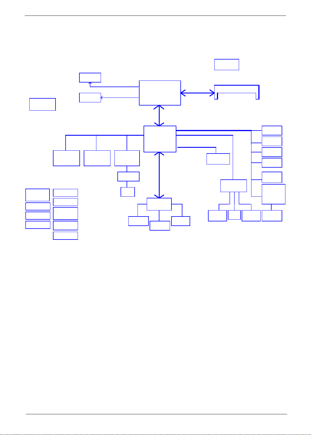
System Block Diagram
DDR2
CRT Conn
RGB
Thermal Sensor
EMC1402
LCD Conn.
LVDS
DMI
X2 mode
GEN1
Pineview
FCBGA 559
22x22mm
Memory BUS(DDRII)
1.8V DDRII 667
Clock Generator
CK505
DDRII-SO-DIMM
Power ON/OFF
DC IN
BATT IN
CHARGER
MINI Card x1
3G
DC/DC Interface
3VALW/5VALW
0.89VP/1.5VP
0.9VSP/2.5VSP
1.8V/VCCP
CPU_CORE
MINI Card x1
WLAN
PCI-Express
10/100 Ethernet
AR8152L
Transfermer
RJ45
Int.KBD
Tigerpoint
PCBGA360
17x17mm
LPC BUS
ENE KBC
KB926
Touch Pad
SPI
SPI ROM
SATA
USB
HDA
HDD
AMP & INT
Speaker
Aralia Codec
ALC272
INT MIC HeadPhone &
I/O Board
MIC Jack
USB Port X3
BlueTooth
CMOS CAM
3G
WLAN
Card Reader
ENE6252
SD/MMC/MS
CONN
Chapter 1 5
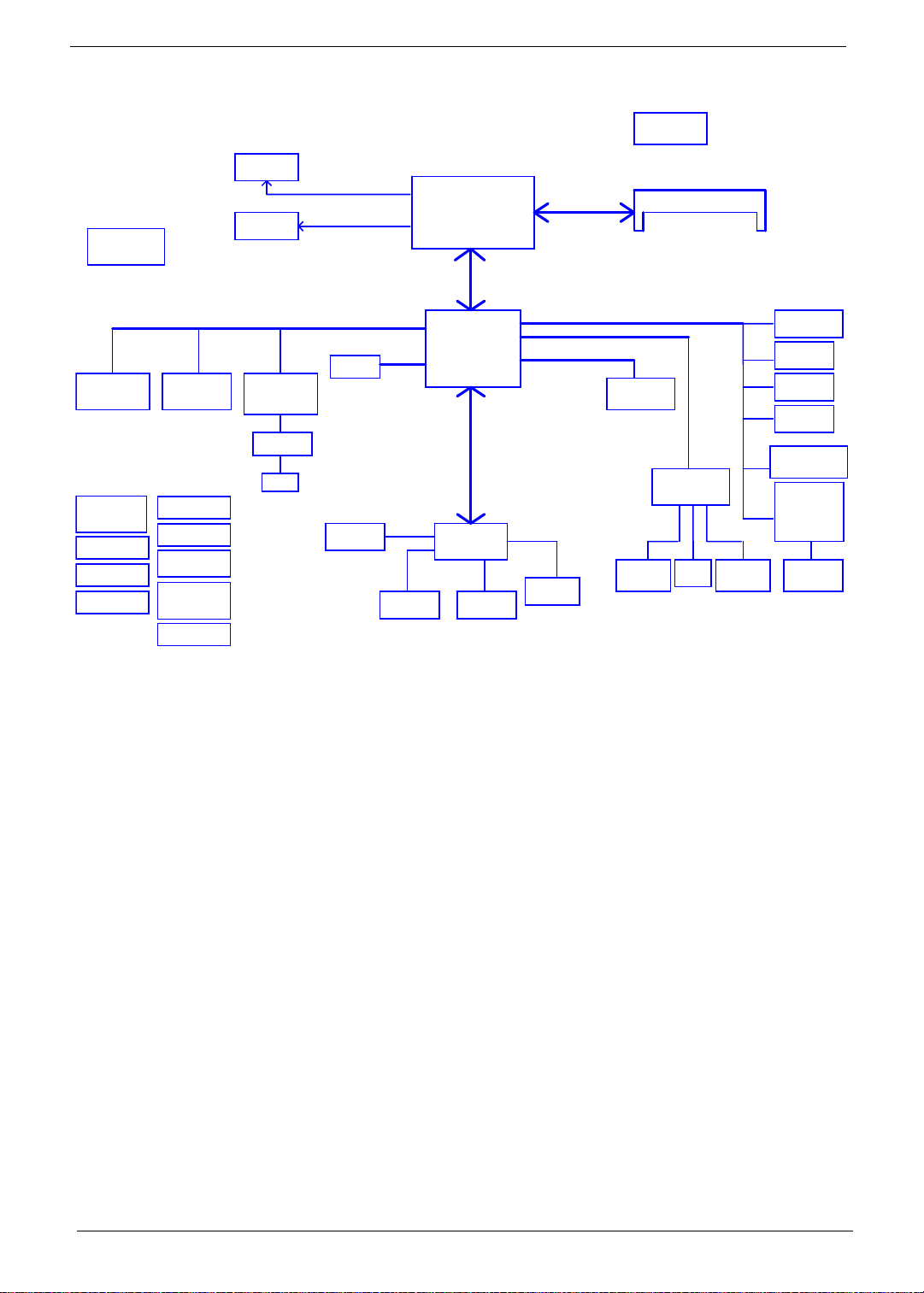
DDR3
Thermal Sensor
EMC1402
CRT Conn
LCD Conn.
RGB
LVDS
DMI
X2 mode
GEN1
Pineview
FCBGA 559
22x22mm
Memory BUS(DDRIII)
1.5V DDRIII 667
Clock Generator
CK505
DDRIII-SO-DIMM
MINI Card x1
3G
Power ON/OFF
DC IN
BATT IN
CHARGER
WLAN
DC/DC Interface
3VALW/5VALW
1.5VP/VCCP
0.89VP/1.8VP
0.75VS
CPU_CORE
PCI-Express
10/100 Ethernet
AR8152
Transfermer
RJ45
TPM
Int.KBD
LPC BUS
Light Sensor
Tigerpoint
PCBGA360
17x17mm
LPC BUS
ENE KBC
KB926
Touch Pad
USB
HDA
SATA
HDD
Aralia Codec
ALC272
SPI
INT MIC HeadPhone &
MIC Jack
SPI ROM
AMP & INT
Speaker
USB Port x2(L)
BlueTooth
CMOS CAM
3G
USB Port x1(R)
Card Reader
ENE6252
SD/MMC/MS
CONN
6 Chapter 1
Your Notebook Tour
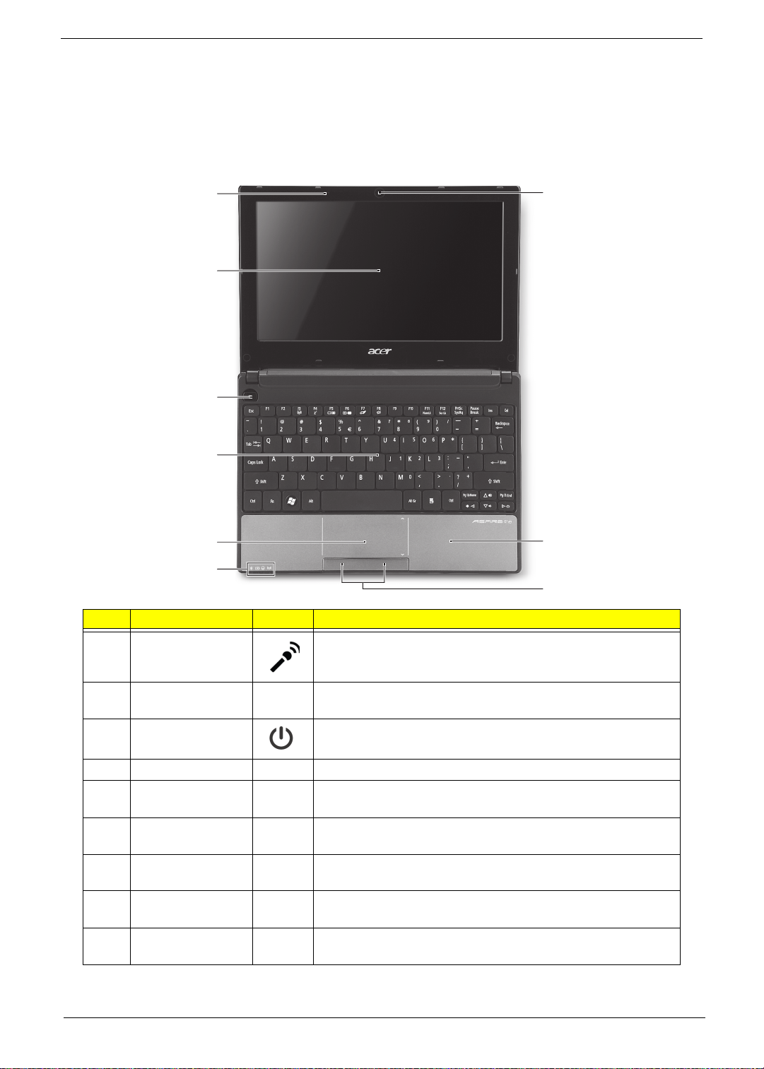
Top View
Top view
1
9
2
3
4
5
8
6
7
No. Component Icon Description
1 Microphone
2 Display screen Also called Liquid-Crystal Display (LCD), displays computer
3 Power button Turns the computer on an d off.
4 Keyboard For entering data into your computer.
5 Touchpad Touch-sensitive pointing device which functions like a
6 Status indicators Light-Emitting Diodes (LED) that light up to show the status of
7 Click buttons (left,
and right)
8 Palmrest Comfortable support area for your hands when you use the
9 Acer Crystal Eye
webcam
NOTE: The front panel indicators are visible even when the computer cover is closed.
Internal microphone for sound recording.
output (configuration may vary by model).
computer mouse.
the computer's functions and components.
The left and right buttons function like the left and right mouse
buttons.
computer.
Web camera for video communication.
Chapter 1 7
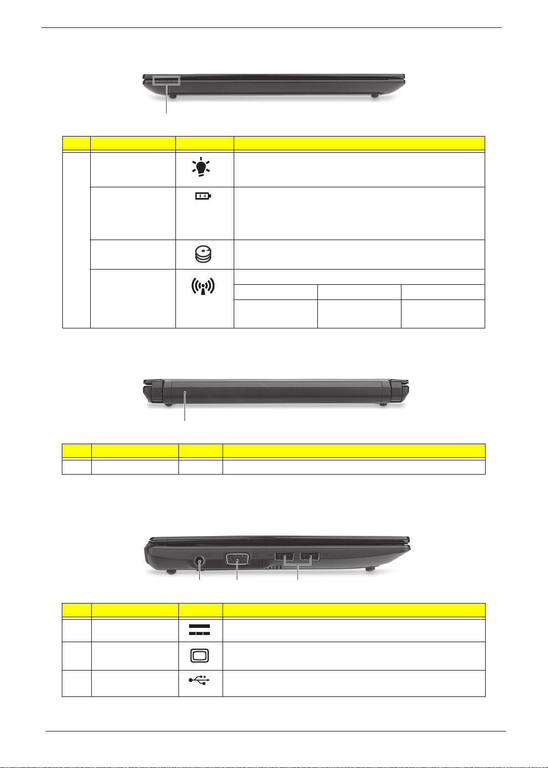
Closed Front View
1
# Component Icon Description
1 Power indicator Indicates the computer's power status.
Battery indicator Indicates the computer's battery status.
1. Charging: The light shows amber when the battery is
charging.
2. Fully charged: The light shows blue when in AC mode.
HDD indicator Indicates when the hard disk drive is active.
Communication
indicator
Indicates the status of 3G/Wireless LAN communication.
Blue light on Orange light on Not lit
3G on / Wi-Fi on
3G on / Wi-Fi off
3G off / Wi-Fi on 3G off / Wi-Fi off
Rear View
1
# Component Icon Description
1 Battery bay Houses the computer’s battery pack.
NOTE: Your computer may be equipped with a different battery to the one in the pi cture.
Left View
213
# Component Icon Description
1 DC-in jack Connects to an AC adapter.
2 External display
(VGA) port
3 USB 2.0 port Connects to USB 2.0 devices (e.g., USB mouse, USB
8 Chapter 1
Connects to a display device (e.g., external monitor, LCD
projector).
camera, etc.).
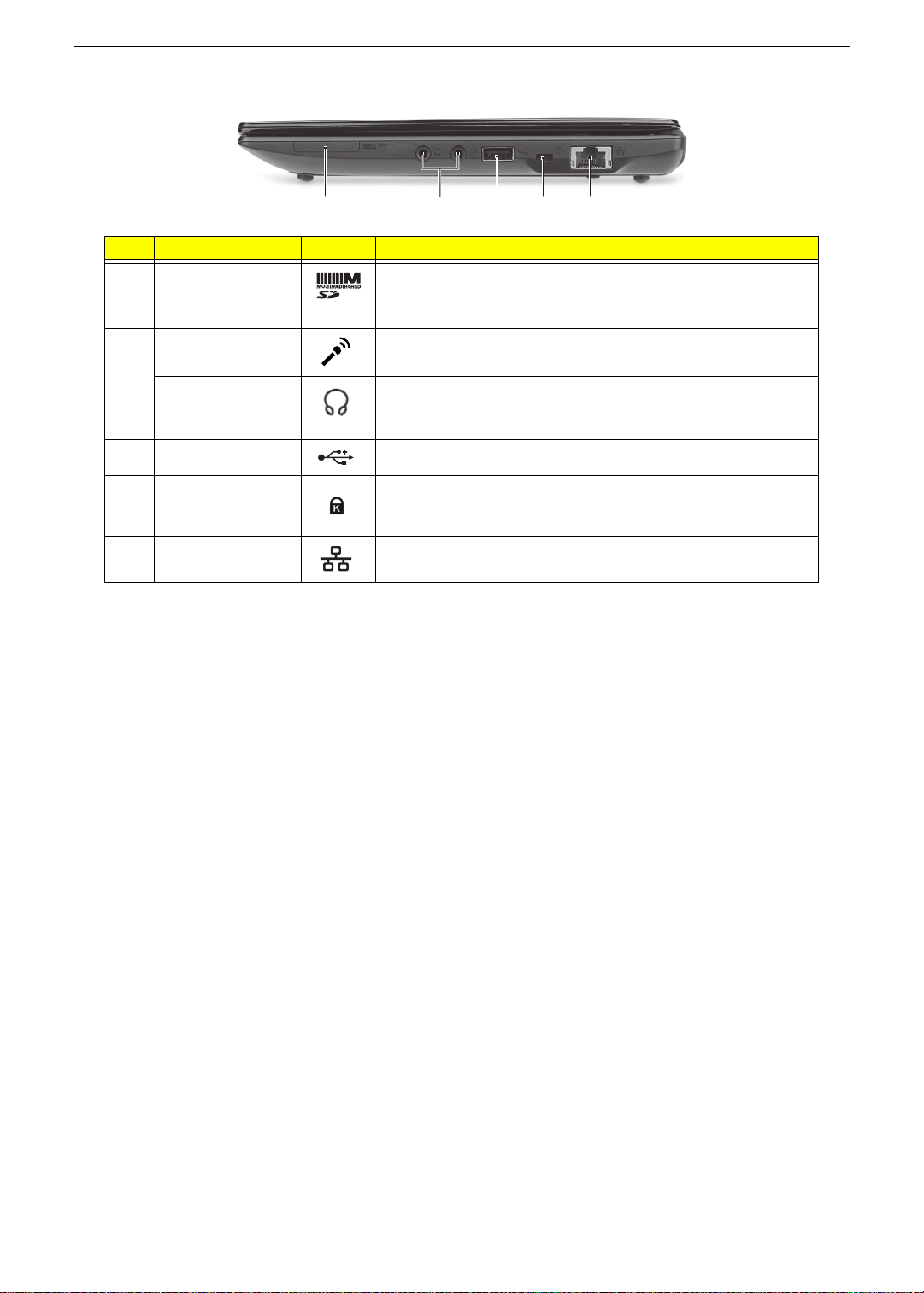
Right View
21345
# Component Icon Description
1 2-in-1 card reader Accepts Secure Digital (SD), MultiMediaCard (MMC).
Note: Push to remove/install the card. Only one card can
operate at any given time.
2 Microphone-in
jack
Accepts input from external microphones.
Headphone/
speaker/line-out
jack
3 USB 2.0 port Connects to USB 2.0 devices (e.g., USB mouse).
4 Kensington lock
slot
5 Ethernet (RJ-45)
port
Connects to line-out audio devices (e.g., speakers,
headphones).
Connects to a Kensington-compatible computer security lock.
Connects to an Ethernet 10/100-based network.
Chapter 1 9
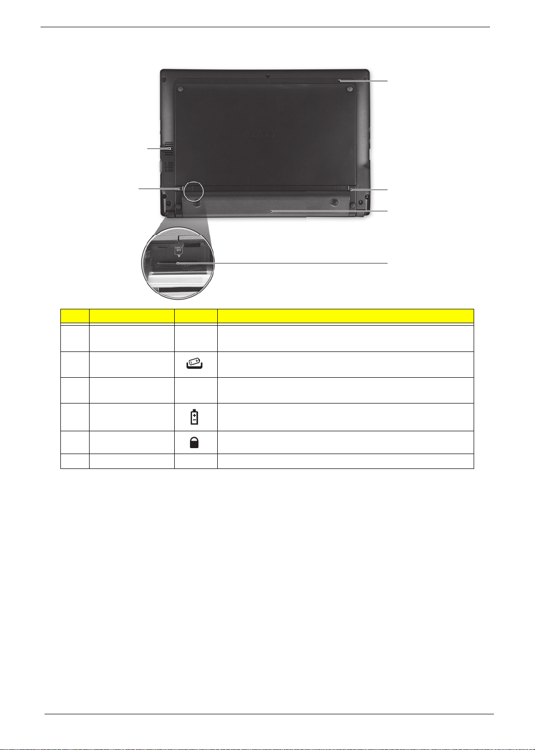
Bottom View
6
1
2
5
4
3
# Component Icon Description
1 Ventilation slots
and/or cooling fan
2 Battery release
latch
3 3G SIM card slot Accepts a 3G SIM card for 3G connectivity (only for certain
4 Battery bay Houses the computer's battery pack.
5 Battery lock Locks the battery in position.
6 Speaker Emits audio from your computer.
Enables the computer to stay cool, even after prolonged use.
Note: Do not cover or obstruct the opening of the fan.
Releases the battery for removal.
models).
10 Chapter 1
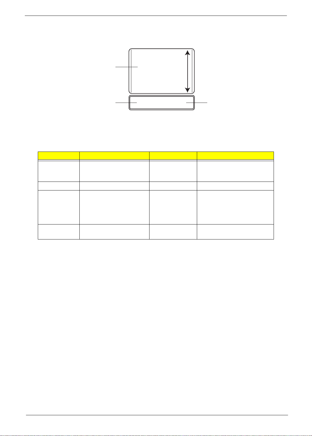
Touchpad Basics
The following items show you how to use the Touchpad:
1
2
• Move your finger across the TouchPad (1) to move the cursor.
• Press the left (2) and right (3) buttons located beneath the TouchPad to perform selection and
execution functions. These two buttons are similar to the left and right buttons on a mouse.
Tapping on the TouchPad is the same as clicking the left button.
Function Left Button (2) Right Button (3) Main TouchPad (1)
Execute Quickly click twice. Tap twice (at the same speed
Select Click once. Tap once.
Drag Click and hold, then use
finger on the TouchPad to
drag the cursor.
Access
context menu
NOTE: When using the T ouchPad, keep it - and your fingers - dry and clean. The TouchPad is sensitive to
finger movement; hence, the lighter the touch, the better the response. Tapping too hard will not
increase the TouchPad’s responsiveness.
Click once.
3
as double-clicking a mouse
button).
Tap twice (at the same speed
as double-clicking a mouse
button); rest your finger on
the TouchPad on the second
tap and drag the cursor.
Chapter 1 11
Using the Keyboard
The Acer Aspire D255 has a close-to-full-sized keyboard and an embedded numeric keypad, separate cursor,
lock, function and special keys.
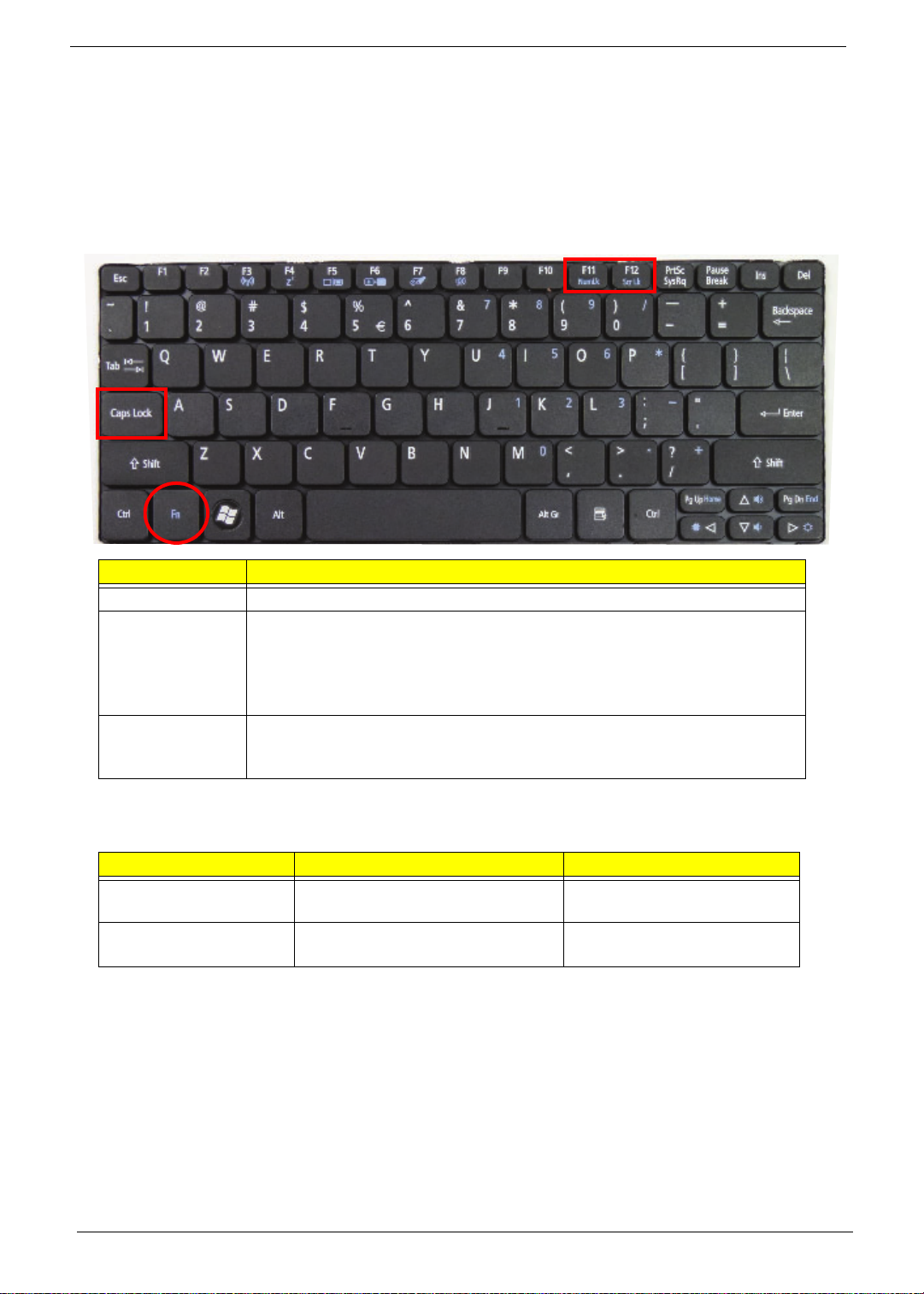
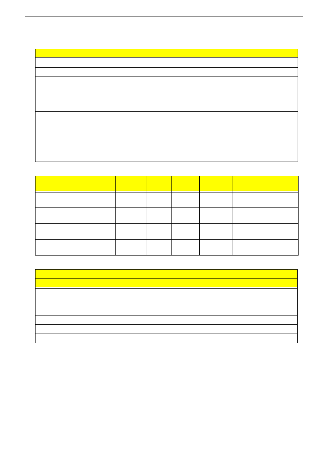
Lock Keys and Embedded Numeric Keypad
The keyboard has three lock keys which you can toggle on and off.
Lock key Description
Caps Lock When Caps Lock is on, all alphabetic characters typed are in uppercase.
Num Lock
<Fn> + <F11>
Scroll Lock <Fn> +
<F12>
When Num Lock is on, the embedded keypad is in numeric mode. The keys
function as a calculator (complete with the arithmetic operators +, -, *, and /). Use
this mode when you need to do a lot of numeric data entry. A better solution
would be to connect an external keypad.
<Fn> + <F11> only for certain models.
When Scroll Lock is on, the screen moves one line up or down when you press
the up or down arrow keys respectively. Scroll Lock does not work with some
applications.
The embedded numeric keypad functions like a desktop numeric keypad. It is indicated by small characters
located on the upper right corner of the keycaps. To simplify the keyboard legend, cursor-control key symbols
are not printed on the keys.
Desired access Num Lock on Num Lock off
Number keys on
embedded keypad
Main keyboard keys Hold <Fn> while typing letters on
12 Chapter 1
Type numbers in a normal manner.
embedded keypad.
Type the letters in a normal
manner.
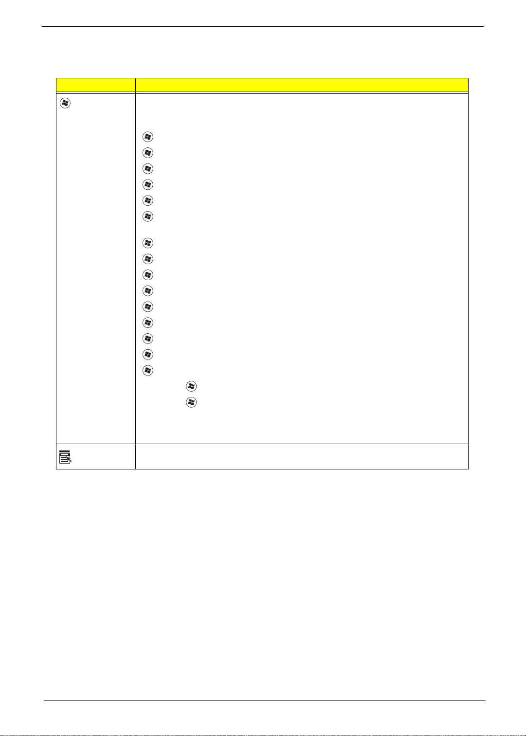
Windows Keys
The keyboard has two keys that perform Windows-specific functions.
Key Description
Windows key Pressed alone, this key has the same effect as clicking on the Windows Start button;
it launches the Start menu. It can also be used with other keys to provide a variety of
functions:
<>: Open or close the S tart menu
<> + <D>: Display the desktop
<> + <E>: Open Windows Explore
<> + <F>: Search for a file or folder
<> + <G>: Cycle through Sidebar gadgets
<> + <L>: Lock your computer (if you are connected to a network domain), or
switch users (if you're not connected to a network domain)
<> + <M>: Minimizes all windows
<> + <R>: Open the Run dialog box
<> + <T>: Cycle through programs on the taskbar
<> + <U>: Open Ease of Access Center
<> + <X>: Open Windows Mobility Center
<> + <BREAK>: Display the System Properties dialog box
<> + <SHIFT+M>: Restore minimized windows to the desktop
<> + <TAB>: Cycle through programs on the taskbar by using Windows Flip 3-D
<> + <SPACEBAR>: Bring all gadgets to the front and select Windows Sidebar
Application
key
<CTRL> +
<CTRL> + <> + <TAB>: Use the arrow keys to cycle through programs on the
Note: Depending on your edition of Windows 7, some shortcuts may not function as
This key has the same effect as clicking the right mouse button; it opens the
application's context menu.
<> + <F>: Search for computers (if you are on a network)
taskbar by using Windows Flip 3-D
described.
Chapter 1 13
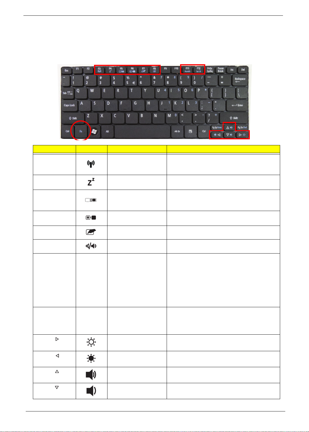
Hot Keys
The computer employs hotkeys or key combinations to access most of the computer's controls like screen
brightness and volume output.
To activate hotkeys, press and hold the <Fn> key before pressing the other key in the hotkey combination.
Hotkey Icon Function Description
<Fn> + <F3> Communication key Enables/disables the computer’s
communication devices. (Communication
devices may vary by configuration.)
<Fn> + <F4> Sleep Puts the computer in Sleep mode.
<Fn> + <F5> Display toggle Switches display output between the display
screen, external monitor (if connected) and
both.
<Fn> + <F6> Screen blank Turns the display screen backlight off to save
power. Press any key to return.
<Fn> + <F7> TouchPad toggle Turns the internal TouchPad on and off.
<Fn> + <F8> Speaker toggle Turns the speakers on and off.
<Fn> + <F11> Num Lock When Num Lock is on, the embedded keypad is
in numeric mode. The keys function as a
calculator (complete with the arithmetic
operators +, -, *, and /). Use this mode when
you need to do a lot of numeric data entry. A
better solution would be to connect an external
keypad.
<Fn> + <F11> only for certain models.
<Fn> + <F12> Scroll Lock When Scroll Lock is on, the screen moves one
line up or down when you press the up or down
arrow keys respectively . Scroll Lock does not
work with some applications.
<Fn> + < > Brightness up Increases the screen brightness.
<Fn> + < > Brightness down Decreases the screen brightness.
<Fn> + < >
<Fn> + < >
Volume up Increases the sound volume.
Volume down Decreases the sound volume.
14 Chapter 1

Using the communication key
Here you can enable and disable the various wireless connectivity devices on your computer.
Press <Fn> + <F3> to bring up the Launch Manager window panel.
A red toggle indicates the device is off. Click On to enable wireless/3G/Bluetooth connection. Click Off to
disable connection.
NOTE: Communication devices may vary by model.
Special Key
Locate the Euro symbol and the US dollar sign at the upper-center and/or bottom-right of your keyboard.
The Euro symbol
1. Open a text editor or word processor.
2. Hold <Alt Gr> and then press the <5> key at the upper-center of the keyboard.
NOTE: Some fonts and software do not support the Euro symbol.
The US dollar sign
1. Open a text editor or word processor.
2. Hold <Shift> and then press the <4> key at the upper-center of the keyboard.
NOTE: This function varies according to the language settings.
Chapter 1 15
Hardware Specifications and Configurations
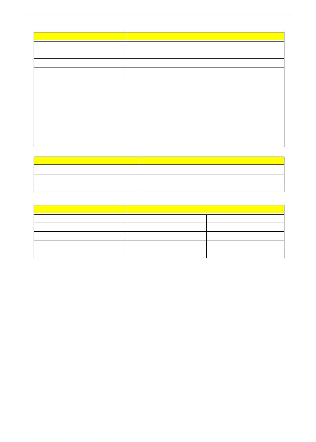
Processor
Item Specification
CPU type Intel® Atom (N455, N475,N550) Processor
CPU package Micro-FCBGA8 packaging technologies
Core Logic • Intel NM10 Express chipset
• Tiger Point(NM10 Express chipset)
• On die 512-kB, 8-way L2 cache
• On die 2*512-kB, 8-way L2 cache(N550)
Chipset • Tiger Point Chipset (NM10)
• ENE KB926 for Keyboard Controller, Battery management
Unit, and RTC
• Realtek ALC272X-GR for High Definition Audio Codec.
• Atheros AR8152 for 10/100 LAN
• ENE UB6252 card reader support SD,MMC
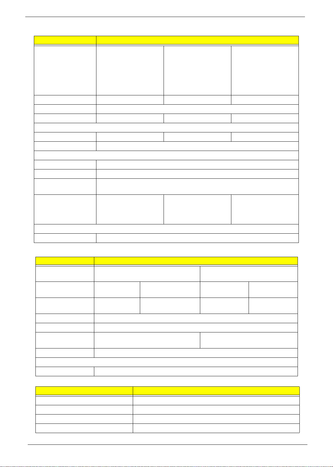
Processor Specifications
Item
N450 1.66
N455 1.66
N475 1.83
N550 1.5 GHz 2 667
CPU
Speed
GHz
GHz
GHz
Cores
1667
1667
1667
Bus
Speed
MHz
MHz
MHz
MHz
Mfg
Tech
45 nm 512 KB Micro-
45 nm 512 KB Micro-
45 nm 512 KB Micro-
45 nm 2*512 KBMicro-
Cache
Size
Package
FCBGA8
FCBGA8
FCBGA8
FCBGA8
Core
Voltage
0.9V-
1.100V
0.8V-
1.175V
0.8V-
1.175V
0.8V-
1.175V
Acer P/N
KC.ANB0
1.450
KC.ANB0
1.455
KC.ANB0
1.475
KC.ANB0
1.550
CPU Fan True Value Table
For N45x N47x OS mode
CPU Temperature Fan Speed (RPM) SPL Spec (dBA)
50 4700 26
54 5200 29
57 5500 31
35 5200 29
53 5200 29
60 5500 31
• Throttling 50%: On=95°C ; OFF=80°C
• OS shut down at100°C ; H/W shut down at 90°C
16 Chapter 1
For N550 OS mode
CPU Temperature Fan Speed (RPM) SPL Spec (dBA)
50 4600 26
54 5400 29
57 5800 31
35 5400 29
53 5400 29
60 5800 31
• Throttling 50%: On=95°C ; OFF=80°C
• OS shut down at100°C ; H/W shut down at 90°C
For N45x N47x w/MCP_Quartic OS mode
CPU Temperature Fan Speed (RPM) SPL Spec (dBA)
35 4600 26
40 5400 29
45 5800 31
• Throttling 50%: On=95°C ; OFF=80°C
• OS shut down at100°C ; H/W shut down at 90°C
System Memory (DDR2)
Item Specification
Memory controller Support s DIMM Speed
Memory size 1GB/2GB DDR2 RAM (Note: 2GB DDR2 not available for all
operating systems)
DIMM socket number 1
Supports memory size per socket 2 GB
Supports maximum memory size 2 GB
Supports DIMM type DDR II 667Mhz SDRAM memory interface design
Supports DIMM Speed 667Mhz SDRAM
Support DIMM voltage 1.8V
Supports DIMM package One socket 200-pin
System Memory (DDR3)
Item Specification
Memory controller Built in
Memory size 1GB/2GB DDR3 RAM (if 2Gb die support is available)
DIMM socket number 1
Supports memory size per socket 2 GB
Supports maximum memory size 2 GB
Supports DIMM type DDR III 667Mhz SDRAM memory interface design
Supports DIMM Speed 667Mhz SDRAM
Support DIMM voltage 1.5V
Supports DIMM package One socket 204-pin
Chapter 1 17
Video Interface
Item Specification
Chipset Built-in Intel® GMA 3150
Package FCBGA559
Interface LVDS / CRT
Supports ZV (Zoomed Video) port TBD
Compatibility TBD
Sampling rate 60Hz
Internal microphone Yes
Internal speaker / quantity Yes / 2
VRAM
Item Specification
Chipset Built-in Intel® GMA 3150
Memory size 64 MB dedicated memory
Interface DDRIII
BIOS
Item Specification
BIOS vendor InsydeH20
BIOS Version V1.00 for DDR2 SKU; V3.00 for DDR3 SKU
BIOS ROM type Flash
BIOS ROM size 2 MB
Support protocol Support ISIPP
Support Acer UI
Support multi-boot
Suspend to RAM (S3)/Disk (S4)
Various hot-keys for system control
Support SMBUS 2.0, PCI2.3
ACPI 3.0 compliance with Intel Speed Step Support C1, C2, C3,
C4 and S3, S4 for mobile CPU
DMI utility for BIOS serial number configurable/asset tag
Support PXE
Support Y2K solution
Support Win Flash Wake on LAN from S3
Wake on LAN from S4 in AC mode
System information
18 Chapter 1
LAN Interface
Item Specification
LAN Chipset AR8152L
Support LAN protocol TBD
LAN connector type RJ45
LAN connector location Right side
Features • Integrated 10/100 BASE-T transceiver
• PCI Bus Interface
• Supports PCI Rev v2.3 at 33MHz
• 2 available PCI REQ/GNT pairs. Support for 64-bit
addressing on PCI using DAC protocol.
• Power Management Logic
• Supports ACPI 3.0
• ACPI-defined power states (C1, S1, S3-S5 for Netbook)
• Wake on LAN support compliant with ACPI 3.0
Wireless Module 802.11b/g/Draft-N
Item Specification
Manufacturer Atheros, Broadcom, RTL
Model HB93/HB95, 4313, 8191
Supported Standards 802.11 b+g, Draft-N
Battery
Item Specification
Vendor & model name SANYO AL10A SANYO AL10B
Battery Type Li-ion Li-ion
Pack capacity 2200 mAh 4400 mAh
Number of battery cell 3 6
Package configuration 3S1P 3S2P
Chapter 1 19
Hard Disk Drive Interface
Item Specification
Vendor & Model
Name
Western Digital
WD1600BEVT22A23T0,
Hitachi
HTS545016B9A300,
Toshiba MK1665GSX,
Seagate ST9160314AS
Western Digital
WD2500BEVT22A23T0,
Hitachi
HTS545025B9A300,
Toshiba MK2565GSX,
Seagate ST9250315AS
Western Digital
WD3200BEVT22A23T0,
Hitachi
HTS545032B9A300,
Toshiba MK3265GSX,
Seagate ST9320315AS
Capacity (GB) 1600GB 250GB 320GB
Bytes per sector 512
Data heads 1, 2, 1, 2 2, 2, 2, 2 2, 3, 2, 3
Drive Format
Disks 1 1 1, 2, 1, 2
Spindle speed (RPM) 5400
Performance Specifications
Buffer size 8MB
Interface SATA
Fast data transfer
3.0Gbits/s
rate
Media data transfer
rate
106Mbytes/s,
845Mbits/s,
1175Mbits/s,
1273.3Mbits/s
106Mbytes/s,
845Mbits/s,
1 175Mbit/s,
1031.7Mbits/s
106Mbytes/sm,
845Mbits/s,
1175Mbits/s,
1273.3Mbits/s
DC Power Requirements
Voltage tolerance 5V
Super-Multi Drive Module (Not available with this module)
Item Specification
Vendor & model
name
Performance
Specification
Transfer rate (MB/
sec)
Buffer Memory
Interface
Applicable disc
formats
Loading mechanism
Power Requirement
Input Voltage
Bluetooth Interface
Item Specification
Chipset Atheros AR3011/ Broadcom BCM2070/ Broadcom BCM2046
Protocol 3.0+HS
Interface USB 2.0
Connector type JST SM08B - SURS - TF
20 Chapter 1
 Loading...