


Aspire M5640
Aspire M3640
Aspire M1640
Service Guide
Service guide files and updates are available on the AIPG/CSD web; for more information please refer to http://csd.acer.com.tw
PRINTED IN TAIWAN

Revision History
Please refer to the table below for the updates made on Aspire M5640/Aspire M3640/ Aspire M1640 service guide.
Date |
Chapter |
Updates |
|
|
|
|
|
|
|
|
|
II

Copyright
Copyright © 2007 by Acer Incorporated. All rights reserved. No part of this publication may be reproduced, transmitted, transcribed, stored in a retrieval system, or translated into any language or computer language, in any form or by any means, electronic, mechanical, magnetic, optical, chemical, manual or otherwise, without the prior written permission of Acer Incorporated.
Disclaimer
The information in this guide is subject to change without notice.
Acer Incorporated makes no representations or warranties, either expressed or implied, with respect to the contents hereof and specifically disclaims any warranties of merchantability or fitness for any particular purpose. Any Acer Incorporated software described in this manual is sold or licensed "as is". Should the programs prove defective following their purchase, the buyer (and not Acer Incorporated, its distributor, or its dealer) assumes the entire cost of all necessary servicing, repair, and any incidental or consequential damages resulting from any defect in the software.
Acer is a registered trademark of Acer Corporation. Intel is a registered trademark of Intel Corporation.
Pentium 4 and Celeron are trademarks of Intel Corporation.
Other brand and product names are trademarks and/or registered trademarks of their respective holders.
III
Conventions
The following conventions are used in this manual:
SCREEN Denotes actual messages that appear on screen.
MESSAGES
NOTE Gives bits and pieces of additional information related to the current topic.
WARNING Alerts you to any damage that might result from doing or not doing specific actions.
CAUTION Gives precautionary measures to avoid possible hardware or software problems.
IMPORTANT Remind you to do specific actions relevant to the accomplishment of procedures.
IV

Preface
Before using this information and the product it supports, please read the following general information.
1.This Service Guide provides you with all technical information relating to the BASIC CONFIGURATION decided for Acer's "global" product offering. To better fit local market requirements and enhance product competitiveness, your regional office MAY have decided to extend the functionality of a machine (e.g. add-on card, modem, or extra memory capability). These LOCALIZED FEATURES will NOT be covered in this generic service guide. In such cases, please contact your regional offices or the responsible personnel/channel to provide you with further technical details.
2.Please note WHEN ORDERING FRU PARTS, that you should check the most up-to-date information available on your regional web or channel. If, for whatever reason, a part number change is made, it will not be noted in the printed Service Guide. For ACER-AUTHORIZED SERVICE PROVIDERS, your Acer office may have a DIFFERENT part number code to those given in the FRU list of this printed Service Guide. You MUST use the list provided by your regional Acer office to order FRU parts for repair and service of customer machines.
V
Chapter 1 System Specifications 1
Features……………………………………………………………………………………………... 1 Main board Placement…………………………………………………….……..……………..7 Block Diagram…………………………………………………………..………………...………..8 Aspire M5640 Front Panel………………………………………..…….………..…..……....9 Aspire M5640 Rear Panel…………………..…………………………….……………………10 Aspire M3640 Front Panel……………………………………………………………………..11 Aspire M3640 Rear Panel……………………….…………………………………..……….12 Aspire M1640 Front Panel……………………………………………………………………..13 Aspire M1640 Rear Panel……………………….…………………………………..……….14 Hardware Specifications and Configurations………………….…….……..15 Power Management Function (ACPI support function)…………………………..…...19
Chapter 2 System Utilities 20
Entering Setup…………………………………………………………………………..21 P r o d u c t I n f o r m a t i o n … … … … … … … … … … … … … … … … … … … … … . . 2 3 Standard CMOS Features……………………………….……………………………………24 Advanced BIOS Features………………………………………..……………………27 Integrated Peripherals…………………………...…………………………………………..31 P o w e r M a n a g e m e n t … … … … … … … … … … … … … … … … … … … … … … 3 8 P n P / P C I C o n f i g u r a t i o n … … … … … … … … … … … … … … … … … … … … . 4 1 P C H e a l t h S t a t u s … … … … … … … … … … … … … … … … … … … … … … … . . . 4 3 F r e q u e n c y/ V o l t a g e C o n t r o l … … … … … . . … … … … … … … … … … . … … . 4 4 Load Default Se ttings ………………………………………………..……. 46 S e t S u p e r v i s o r / U s e r P a s s w o r d … … … … … … … … … … … … . … … … … 4 7 S a v e & E x i t S e t u p … … … … … … … … … … … … … … … … … … … . … … … … 4 9 E x i t W i t h o u t S a v i n g … … … … … … … … … … … … … … … … … … … . … … . . 5 0
Chapter 3 Machine Disassembly and Replacement 51
G e n e r a l I n f o r m a t i o n … … … … … … … … … … … … … … … … … … … … … . 5 2 D i s a s s e m b l y P r o c e d u r e … … … … … … … … … … … … … … … … … … … … 5 3 Aspire M5640/3640/1640 Disassembly Procedure…………….…..……54
Chapter 4 Troubleshooting 70
Chapter 5 Jumper and Connector Information 71
Jumper Setting …………………………………………………..……………….. 71
Chapter 6 FRU (Field Replaceable Unit) List 80
E x p l o d e d D i a g r a m … … … … … … … … … … … … … … … … … … … … … … . 8 1

System Specifications
Features
Operating System
Microsoft Windows Vista (Home Basic, Home Premium, Business)
Processor
Socket Type: Intel® Socket T LGA 775 pin
Processor Type:
Intel Celeron / Celeron D / Pentium D /Pentium Dual Core/ Core 2 Duo / Core2 Quad / Yorkfield / Wolfdale CPUs FSB 533/800/1066/1333 MHz CPUs
Chipset
NV MCP73PV/S & NV MCP73VE
PCB
Form Factor: Micro ATX
Dimension/Layer: 244mm x244mm
Memory
Memory Type: DDR2 533/667/800
Support single channel 64 bit mode with maximum memory size up to 4GB Support un-buffered DIMM (MCP73S)
DIMM Slot: 2
Memory Max: 512MB to 4GB DDR2 memory technologies
Capacity: Up to 2GB per DIMM with maximum memory size up to 4GB
PCI
PCI Express Slot Type: x16
PCI Express x16 Slot Quantity: 1
PCI Express Slot Type: x1
PCI Express x1 Slot Quantity: 1
1

PCI Slot Type: PCI 2.3 5V slots
PCI Slot Quantity: 2
FDD
Slot Quantity: 1
Design Criteria:
Should support 1.44MB/3 mode 3.5” Devices
IDE
Slot Type: 40pin PATA IDE slot
Slot Quantity: 1
Transfer rate support:
PIO Mode: 0/1/2/3/4
ATA mode: 33/66/100/133
Storage Type support:
HDD/CD-ROM/CD-RW/DVD-ROM/DVD-RW/DVD+
RW/DVD Dual/DVD SuperMultiPlus/HD
DVD/BlueRay DVD
SATA
Slot Type: SATA slot
Slot Quantity: 4
Storage Type support:
HDD/CD-ROM/CD-RW/DVD-ROM/DVD-RW/DVD+RW/DVD
Dual/DVD SuperMultiPlus/Blu-Ray ODD
Audio
Audio Type: HD audio codec
Audio Channel: 7.1 channel
Audio Controller /Codec: ALC888S HD codec 7.1
Connectors support:
2

Rear 6 jack follow HD audio definition, example as below Audio jacks color coding: should meet Microsoft Windows Logo
Program Device Requirements: Audio-0002
1 S/PDIF-out header (1*4)
1 AUX-In header (1*4)
1 front panel audio header (2*5)
Add HD de-pop CKT (the attachment is the reference, please propose your solution)
S/N ratio: 90 dB at rear output jack
LAN
MAC Controller: NV MCP73PV/S
Intel 82566DC (10M/100M/1000M LAN)
PHY: Realtek 8211BL Gigabit Ethernet Phy.
USB
Controller Type: NV MCP73PV/S
Ports Quantity: 10
4 back panel ports On-board: 3 2*5 headers
4 ports for front daughter board
4 ports for rear I/O
2 ports for internal card reader.
Connector Pin: standard Intel FPIO pin definition
Data transfer rate support:
USB 2.0/1.1
1394
Controller: VIA VT6308P 1394a controller
Connector Quantity: 2
3

1 rear 6pin IEEE1394 port
1 2x5pin onboard jumper
BIOS
BIOS Type: Phoenix Award or AMI Kernel with Acer skin
Size: 4Mb
Note:
Boot ROM should be included (PXE function should be built in with default and RPL function is optional by service BIOS)
BIOS shall auto detect FDD to avoid checksum error when boot
I/O Connector
Controller: Super I/O ITE 8718FX (F stepping or after; must full support Intel platform)
Rear I/O Connector
1 PS/2 Keyboard port,
1 PS/2 Mouse port,
1 COM port
1 DVI port (Aspire M1000 series only)
1 HDMI port (Aspire M3000/5000 series only),
1 D-Sub port,
1 RJ45 LAN port,
1 IEEE 1394 port (6 pin) (Aspire sku only)
4 USB ports
7.1 channel phone jack (6 audio jacks)
On-board connectors
1 CPU socket
2 DDR-2 memory sockets
1 PCI Express x16 slot
4
1 PCI Express x 1 slot
2 PCI slots
1 FDD slot
1 PATA connector
4 SATA connectors
3 2*5 pin Intel FPIO specification USB pin connectors (follow Intel FPIO standard Specification)
1 2*5 pin IEEE1394 jumper (reserve header on all SKU)
1 2*5 pin Intel FPIO spec. Microphone In/ Headphone Out pin connectors 1 serial port 2*5 pin connector (reserve header on all SKU)
1 AUX-In 4pin connector
1 1*4 S/PDIF out header (reserve header on all sku) 1 4 pin CPU Fan connector
1 3 pin System FAN connector with linear circuit
1 24pin + 4pin ATX interface PS3/PS2 SPS connector
1 2*7 pin front panel IO header
1 Jumper for clear CMOS
1 on board buzzer
Color management for on board connecter (pls provide proposal)
Power Supply
Power Supply Mounting Features
Chassis accepts ATX-style power supply
Chasses accepts PS2, PS3 style power supply
Features for internal mounting tab
Location of 4 external mounting holes
Power Supply Electrical Design Feature
300W/250W in stable mode (Acer Assign System Power Unit)
5

Design for Intel Broadwater/ICH8 series chipset compatible system Voltage design should be covered +5V, +3.3V, +12V, +5VSB, -12V
(attention to 12V output capability)
Demand for both PFC/Non-PFC solutions (two different quotations are needed)
Minimum 2 Serial ATA power connector solution should be included (by default)
Minimum 3 big 4-pin power connector included
Minimum 1 small 4-pin power connector included
PFC version will not provide switch selector for 115/230V AC input but it should be universal for Europe and China
Non-PFC version should provide switch selector for 115/230V AC input and universal for worldwide
PS2 style
6

Main board Placement
7

Block Diagram
8
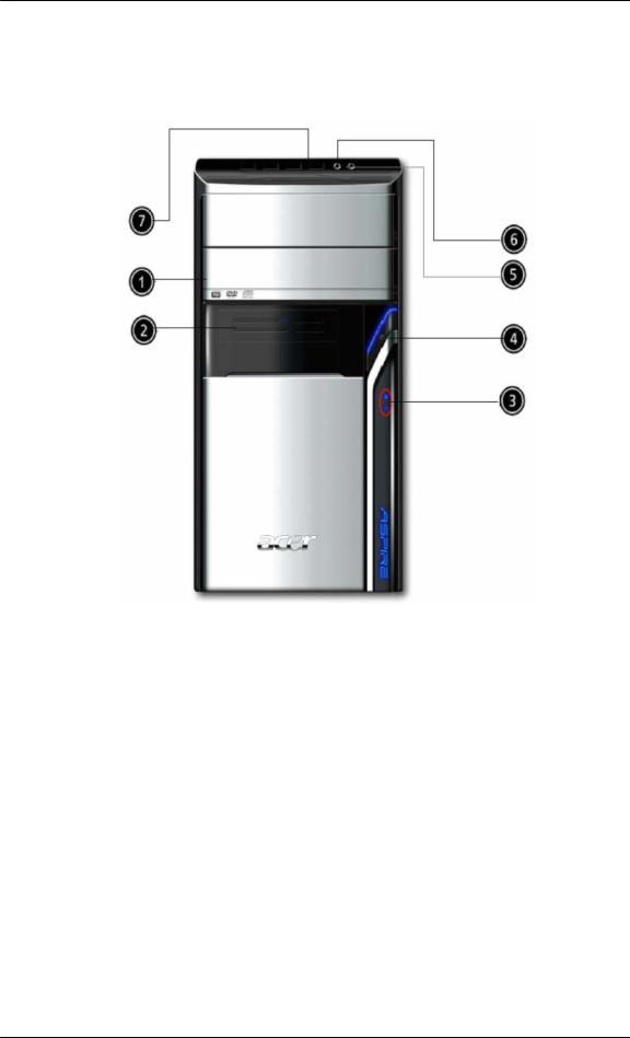
Aspire M5640 Front Panel
The computer’s front panel consists of the following:
Label |
Description |
1 |
Optical drive |
|
|
2 |
Card reader |
|
|
3 |
Power and HDD LED |
|
|
4 |
Power button |
|
|
5 |
Speaker or headphone |
|
|
6 |
Microphone jack |
|
|
7 |
USB ports |
|
|
9
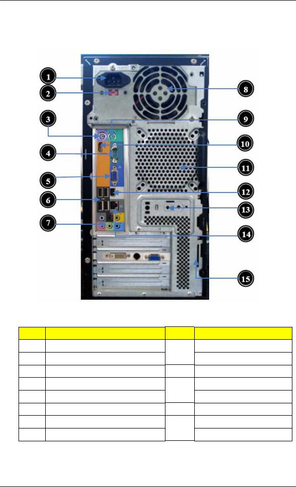
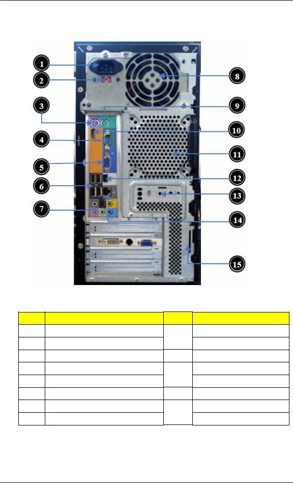
Aspire M5640 Rear Panel
Label Description
1Power card socket
2Voltage selector switch 3 PS/2 keyboard connector
4COM port
5Monitor connector
6USB 2.0 ports
7Audio port
8Fan aperture
Label Description
9PS/2 mouse connector
10HDMI port
11System Fan connector
12IEEE 1394 port
13SPDIF port
14LAN port
15Lock Handle
10
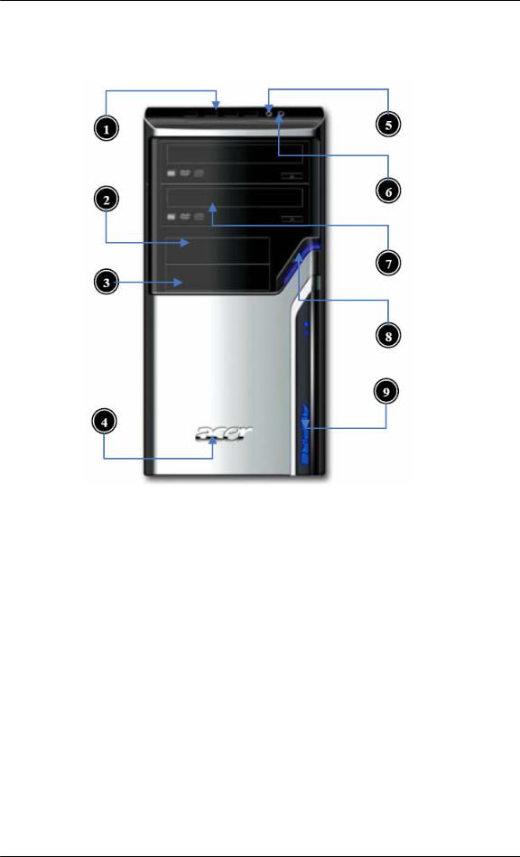
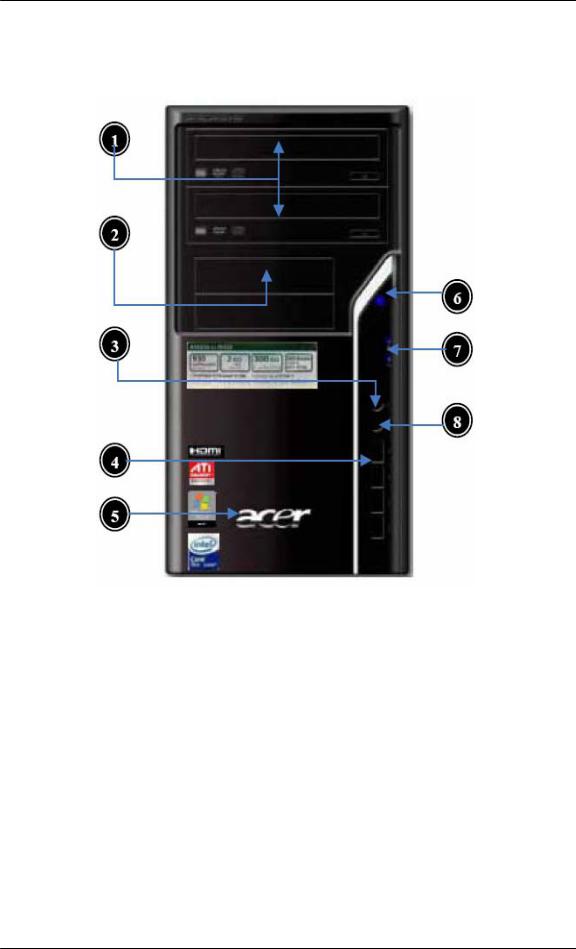
Aspire M3640 Front Panel
Label |
Description |
1 |
USB ports |
|
|
2 |
Floppy disk drive |
|
|
3 |
Card reader cover |
|
|
4 |
Acer Logo |
|
|
5 |
Microphone jack |
|
|
6 |
Speaker or headphone |
|
|
7 |
Optical drive |
|
|
8 |
Power button |
|
|
9 |
LED module |
|
|
11
Aspire M3640 Rear Panel
Label Description
1Power card socket
2Voltage selector switch 3 PS/2 keyboard connector
4COM port
5Monitor connector
6USB 2.0 ports
7Audio port
8Fan aperture
Label Description
9PS/2 mouse connector
10HDMI port
11System Fan connector
12IEEE 1394 port
13SPDIF port
14LAN port
15Lock Handle
12
Aspire M1640 Front Panel
Label |
Description |
1 |
Optical drive |
|
|
2 |
Floppy disk drive |
|
|
3 |
Speaker or headphone |
|
|
4 |
USB Ports |
|
|
5 |
Acer Logo |
|
|
6 |
Power button |
|
|
7 |
LED Module |
|
|
8 |
Microphone jack |
|
|
13
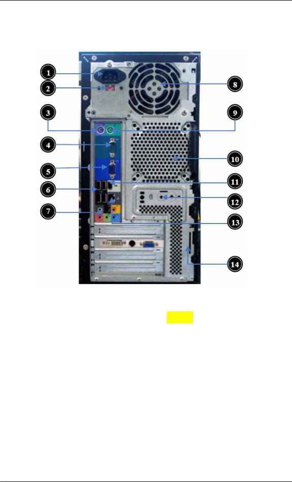
Aspire M1640 Rear Panel
Label |
Description |
Label |
Description |
1 |
Power card socket |
8 |
Fan aperture |
|
|
|
|
2 |
Voltage selector switch |
9 |
PS/2 mouse connector |
|
|
|
|
3 |
PS/2 keyboard connector |
10 |
System Fan connector |
|
|
|
|
4 |
COM port |
11 |
IEEE1394 port |
|
|
|
|
5 |
Monitor connector |
12 |
SPDIF port |
|
|
|
|
6 |
USB 2.0 ports |
13 |
LAN port |
|
|
|
|
7 |
Audio port |
14 |
Lock Handle |
|
|
|
|
14
Hardware Specifications and Configurations
Processor
Item |
Specification |
Type |
Processor Type: Intel Celeron / Celeron D / |
|
Pentium D /Pentium Dual Core / Core 2 Duo / |
|
Core2 Quad / Yorkfield / Wolfdale CPUs |
|
|
Socket |
LGA 775 pin |
|
|
FSB |
533/800/1066/1333 MHz CPUs |
|
|
Minimum operating speed |
0 MHz (If Stop CPU Clock in Sleep State in BIOS |
|
Setup is set to Enabled.) |
|
|
BIOS
|
Item |
|
Specification |
|
BIOS code programmer |
Phoenix Award or AMI Kernel with Acer |
|
|
|
skin |
|
|
|
|
|
|
BIOS version |
V6.0 |
|
|
|
|
|
|
BIOS ROM type |
SPI Flash |
|
|
|
|
|
|
BIOS ROM size |
4Mb |
|
|
|
|
|
|
Support protocol |
SMBIOS (DMI) 2.4/DMI 2.0 (log file) |
|
|
|
|
|
|
Device Boot Support |
- 1st priority: SATA HDD |
|
|
|
- 2nd priority: CD-ROM |
|
|
|
- |
3rd priority: FDD |
|
|
- |
4th priority: LAN |
|
|
- 5th priority: USB device |
|
|
Support to LS-120 drive |
YES |
|
|
|
|
|
|
Support to BIOS boot block |
YES |
|
|
feature |
|
|
|
|
|
|
BIOS Hotkey List |
|
|
|
|
Hotkey |
Function |
Description |
|
|
Del |
Enter BIOS Setup Utility |
Press while the system is booting to |
|
|
|
|
enter BIOS Setup Utility. |
|
|
|
|
|
|
|
|
|
|
|
|
|
|
15 |
|

Main Board Major Chips
Item |
Specification |
North Bridge |
NV MCP73PV/S & NV MCP73VE |
|
|
South Bridge |
NV MCP73PV/S & NV MCP73VE |
|
|
APG controller |
NV MCP73PV/S & NV MCP73VE |
|
|
Super I/O controller |
ITE 8718FX |
|
|
Audio controller |
Realtek HD audio codec ALC888S HD codec 7.1 |
|
(co-lay with ALC888) |
|
|
LAN controller |
Realtek 8211BL Gigabit Ethernet Phy. |
|
|
HDD controller |
NV MCP73PV/S &NV MCP73VE |
|
|
Keyboard controller |
ITE 8718FX |
|
|
Memory Combinations
Slot |
Memory |
Total Memory |
|
|
|
Slot 1 |
512MB, 1GB, 2GB |
512MB~2GB |
|
|
|
Slot 2 |
512MB, 1GB, 2GB |
512MB~2GB |
|
|
|
Maximum System Memory Supported |
512MB~4GB |
|
|
|
|
System Memory
|
Item |
Specification |
|
|
Memory slot number |
2 slot |
|
|
|
|
|
|
Support Memory size per socket |
512MB/1GB/2GB |
|
|
|
|
|
|
Support memory type |
DDR2 |
|
|
|
|
|
|
Support memory interface |
DDR2 800MHz |
|
|
|
|
|
|
Support memory voltage |
1.8V |
|
|
|
|
|
|
Support memory module package |
240-pin DDR2 |
|
|
|
|
|
|
Support to parity check feature |
Yes |
|
|
|
|
|
|
Support to error correction code |
No |
|
|
(ECC) feature |
|
|
|
|
|
|
|
Memory module combinations |
You can install memory modules in any |
|
|
|
combination as long as they match the |
|
|
|
above specifications. |
|
|
|
|
|
|
|
|
|
|
|
16 |
|

Audio Interface
Item |
Specification |
Audio controller |
NV MCP73PV/S & NV MCP73VE |
|
|
Audio controller type |
ALC888S |
|
|
Audio channel |
codec 7.1 |
|
|
Audio function control |
Enable/disable by BIOS Setup |
|
|
Mono or stereo |
Stereo |
|
|
Compatibility |
Sound Blaster Pro/16 compatible |
|
Mixed digital and analog high |
|
performance chip Enhanced stereo |
|
full duplex operation High |
|
performance audio accelerator and |
|
AC’97 support Full native DOS |
|
games compatibility Virtual FM |
|
enhances audio experience through |
|
real-time FM-to-Wavetable |
|
conversionMPU-401 (UART mode) |
|
interface for Wavetable synthesizers |
|
and MIDI devices Integrated dual |
|
game port Meets AC’97and WHQL |
|
specifications |
|
|
Music synthesizer |
Yes, internal FM synthesizer |
|
|
Sampling rate |
48 KHz (max.) |
|
|
MPU-401 UART support |
Yes |
|
|
Microphone jack |
Supported |
|
|
Headphone jack |
Supported |
|
|
SATA Interface |
|
Item |
Specification |
SATA controller |
NV MCP73PV/S & NV MCP73VE |
|
|
SATA controller resident bus |
PCI bus |
|
|
Number of SATA channel |
SATA X 4 |
|
|
Support bootable CD-ROM |
YES |
|
|
17

Floppy disk drive Interface
Item |
Specification |
Floppy disk drive controller |
ITE 8718FX |
|
|
Floppy disk drive controller resident bus |
ISA bus |
|
|
Support FDD format |
360KB, 720KB, 1.2MB, 1.44MB, |
|
2.88MB |
|
|
Parallel Port |
|
Item |
Specification |
Parallel port controller |
ITE 8718FX |
|
|
Parallel port controller resident bus |
ISA bus |
|
|
Number of parallel parts |
1 |
|
|
Support ECP/EPP |
SPP / Bi-directional / ECP / EPP |
|
|
Connector type |
25-pin D-type female connector |
|
|
Parallel port function control |
Enable/disable by BIOS Setup |
|
|
Optional EV+CP DMA channel (in |
DMA channel 1 |
BIOS setup) |
DMA channel 3 |
|
|
Optional parallel port I/O address |
378h |
(via BIOS setup) |
278h |
|
|
Optional parallel port IRQ (via |
IRQ5 |
BIOS setup) |
IRQ7 |
|
|
USB Port |
|
|
Item |
Specification |
|
|
Universal HCI |
USB 2.0/1.1 |
|
|
|
|
|
|
USB Class |
Support legacy keyboard for legacy |
|
|
|
mode |
|
|
|
|
|
|
USB Connectors Quantity |
4 ports for front daughter board |
|
|
|
4 ports for rear I/O |
|
|
|
2 ports for internal card reader. |
|
|
|
|
|
|
|
|
|
|
|
18 |
|

Environmental Requirements
Item |
Specification |
Temperature |
|
|
|
Operating |
+5°C ~ +35°C |
|
|
Non-operating |
-20 ~ +60°C (Storage package) |
|
|
Humidity |
|
|
|
Operating |
15% to 80% RH |
|
|
Non-operating |
10% to 90% RH |
|
|
Vibration |
|
|
|
Operating (unpacked) |
5 ~ 500 Hz: 2.20g RMS random, 10 minutes per axis |
|
in all 3 axes |
|
5 ~500 Hz: 1.09g RMS random, 1 hour per axis in all 3 |
|
axes |
|
|
Power Management
Devices |
S1 |
S3 |
S4 |
S5 |
|
|
|
|
|
Power Button |
V |
V |
V |
V |
|
|
|
|
|
USB Keyboard/Mouse |
V |
V |
N/A |
N/A |
|
|
|
|
|
PME |
Disabled |
Disabled |
Disabled |
Disabled |
|
|
|
|
|
RCT |
Disabled |
Disabled |
Disabled |
Disabled |
|
|
|
|
|
WOR |
Disabled |
Disabled |
Disabled |
Disabled |
|
|
|
|
|
Devices wake up from S3 should be less than
Devices wake up from S5 should be less than 10 seconds
19

System Utilities
The manufacturer or the dealer already configures most systems. There is no need to run Setup when starting the computer unless you get a Run Setup message.
The Setup program loads configuration values into the battery-backed nonvolatile memory called CMOS RAM.
This memory area is not part of the system RAM.
NOTE: If you repeatedly receive Run Setup messages, the battery may be bad/flat. In this case, the system cannot retain configuration values in CMOS.
Before you run Setup, make sure that you have saved all open files. The system reboots immediately after you exit Setup.
20
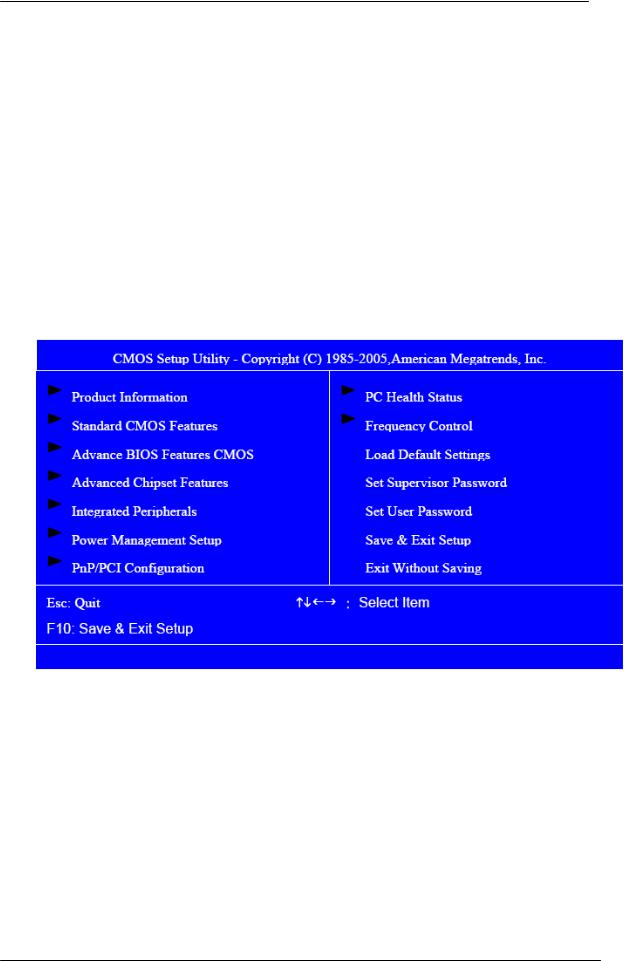
Entering Setup
Power on the computer and the system will start POST (Power On Self Test) process. When the message of “Press DEL to enter SETUP” appears on the screen, press the key of [Delete] to enter the setup menu.
NOTE: If the message disappears before you respond and you still wish to enter Setup, restart the system by turning it OFF and On. You may also restart the system by simultaneously pressing [Ctrl+ Alt+ Delete].
The Setup Utility main menu then appears:
21
 Loading...