


 Loading...
Acer
Aspire M5810
Service Guide
Service guide files and updates are available on the ACER/CSD web; for more information, please refer to http://csd.acer.com.tw
PRINTED IN TAIWAN

Revision History
Please refer to the table below for the updates made on this service guide.
Date |
Chapter |
Updates |
|
|
|
|
|
|
|
|
|
|
|
|
ii

Copyright
Copyright © 2009 by Acer Incorporated. All rights reserved. No part of this publication may be reproduced, transmitted, transcribed, stored in a retrieval system, or translated into any language or computer language, in any form or by any means, electronic, mechanical, magnetic, optical, chemical, manual or otherwise, without the prior written permission of Acer Incorporated.
iii

Disclaimer
The information in this guide is subject to change without notice.
Acer Incorporated makes no representations or warranties, either expressed or implied, with respect to the contents hereof and specifically disclaims any warranties of merchantability or fitness for any particular purpose. Any Acer Incorporated software described in this manual is sold or licensed "as is". Should the programs prove defective following their purchase, the buyer (and not Acer Incorporated, its distributor, or its dealer) assumes the entire cost of all necessary servicing, repair, and any incidental or consequential damages resulting from any defect in the software.
Acer is a registered trademark of Acer Corporation. Intel is a registered trademark of Intel Corporation.
Pentium Dual-Core, Celeron Dual-Core, Core 2 Duo, Core 2 Quad, Celeron, and combinations thereof, are trademarks of Intel Corporation.
Other brand and product names are trademarks and/or registered trademarks of their respective holders.
iv

Conventions
The following conventions are used in this manual:
SCREEN |
Denotes actual messages that appear on screen. |
MESSAGES |
|
|
|
NOTE |
Gives additional information related to the current topic. |
|
|
WARNING |
Alerts you to any physical risk or system damage that might result from doing |
|
or not doing specific actions. |
|
|
CAUTION |
Gives precautionary measures to avoid possible hardware or software |
|
problems. |
|
|
IMPORTANT |
Reminds you to do specific actions relevant to the accomplishment of |
|
procedures. |
|
|
v

Service Guide Coverage
This Service Guide provides you with all technical information relating to the BASIC CONFIGURATION decided for Acer's "global" product offering. To better fit local market requirements and enhance product competitiveness, your regional office MAY have decided to extend the functionality of a machine (e.g. add-on card, modem, or extra memory capability). These LOCALIZED FEATURES will NOT be covered in this generic service guide. In such cases, please contact your regional offices or the responsible personnel/channel to provide you with further technical details.
FRU Information
Please note WHEN ORDERING FRU PARTS, that you should check the most up-to-date information available on your regional web or channel. If, for whatever reason, a part number change is made, it will not be noted in the printed Service Guide. For ACER-AUTHORIZED SERVICE PROVIDERS, your Acer office may have a DIFFERENT part number code to those given in the FRU list of this printed Service Guide. You MUST use the list provided by your regional Acer office to order FRU parts for repair and service of customer machines.
vi

Table of Contents
System Tour |
1 |
Features |
1 |
System Components |
1 |
M/B Placement |
4 |
Block Diagram |
5 |
Front Panel |
6 |
Rear Panel |
7 |
Power Management Function(ACPI support function) |
8 |
System Utilities |
9 |
CMOS Setup Utility |
9 |
Entering CMOS setup |
10 |
Navigating Through the Setup Utility |
10 |
Setup Utility Menus |
11 |
System Disassembly |
24 |
Disassembly Requirements |
24 |
Pre-disassembly Procedure |
25 |
Removing the Side Panel |
26 |
Removing the Front Bezel |
27 |
Removing the Heat Sink Fan Assembly |
28 |
Removing the Processor |
29 |
Removing the VGA Card |
30 |
Removing the TV Tuner Card |
31 |
Removing the Hard Disk Drive |
32 |
Removing the Optical Drive |
34 |
Removing the Power Supply |
35 |
Remove Cables |
36 |
Remove System FAN |
37 |
Removing the Memory Modules |
38 |
Removing the Mainboard |
39 |
System Troubleshooting |
40 |
Power-On Self-Test (POST) |
41 |
POST Error Messages List |
46 |
Error Symptoms List |
53 |
Undetermined Problems |
58 |
Jumper and Connector Information |
59 |
Jumper Setting |
59 |
FRU (Field Replaceable Unit) List |
65 |
Aspire M5810 Exploded Diagram |
66 |
Aspire M5810 FRU List |
68 |
Intel RAID SOP |
76 |
vii

Chapter 1
System Tour
Features
Below is a brief summary of the computer’s many feature:
NOTE: The features listed in this section is for your reference only. The exact configuration of the system depends on the model purchased.
Operating System
•Microsoft Windows 7 Home Premium 64bit
•Microsoft Windows Vista Home Premium SP1 64bit
•Others upon request
Processor
•Socket Type: Intel Socket H2 ,LGA 1156 pin
•Socket Quantity: 1
•Processor Type:
•Inte Lynnfield/Clarkdale with 45nm family mainstream processorsl Celeron 450 processor
•2009B Mainstream (95W) FMB
Chipset
•Intel P55 +H57 (Ibex Peak)
PCB
•4 Layer uATX form factor 9.6in X 9.6in (24.38cm X 24.38cm)
Memory subsystem
•Socket Type: DDR III Un-buffered DIMM connector
•Socket Quantity: 4
•2 channels, 2 DIMMs per channel.
•Different colors for DIMM 0 and DIMM 1
•Max memory of 8 GB supported (using 2Gb tech)
•DDR3 1.5V 1066/1333 (1GB / 2GB / 4GB)
•Design Criteria:
•Must meet Intel Lynnfield and Clarkdale Chipset platform design guide
•Support 1.5V DIMM
•Dual channel should be enabled always when plug-in 2 same memory size DDRIII. memory module
Hard disk
•Support up to two SATA ports
•3.5", 25.4mm
•Capacity and models are listed on AVLC
Chapter 1 |
1 |

Optical disk
•Support one SATA 5.25" standard ODD
•Support DVD-ROM, DVD-SuperMulti, BD-combo, BD-rewrite
•Maximum ODD depth to 185mm with bezel
•Models are listed on AVLC
Graphics card support
•No mechanical retriction to support for double slot, full length graphics cards in the single PSIe X16 slot
Serial ATA controller
•Slot Type: SATA connector
•Six SATA ports:
•4 for HDD
•2 for ODD
•Storage Type support:
1.HDD : Support RAID 0/1/5/10 2.Blue Ray ODD
3.AHCI mode supported for internal SATA port
•Slot Type :e-SATA connector :
•Controller: JMB362-QGEZ0A
•2x e-SATA with red color connector at rear IO
Audio
•Chip : Realtek ALC888S HD Audio Codec 7.1 with Dolby HT
•Connectors support:
•Rear 6 jack follow HD audio definition including optical S/PDIF output
•Audio jacks color coding: should meet Microsoft Windows Logo Program Device Requirements: Audio-0002
•1 S/PDIF internal port
•1 front panel audio header (2*5)
LAN
•Controller: Intel PCI-E Gbt LAN controller/PHY
•RJ-45 Back panel port with Link/Activity LEDs
USB ports
•Supports 14 USB ports. All USB ports must be boot-capable includes USB-ODD, USB-HDD, USB-FDD, and etc…
•All USB ports must be 2.0 certified.
•All USB ports must provide the over current protection.
•6 USB port located on rear panel and the others located on front bezel and top bezel.
Extension slot
•Support one PCIe x 16 slot
•Support two PCIe x 1 slots
•Support one PCIe x 4 slot
2 |
Chapter 1 |

Total I/O ports
•One RGB output (Clarkdale CPU only in Q1'10)
•One HDMI output (Clarkdale CPU only in Q1'10)
•One RJ45header
•10 USB ports (6 on the back, 2 on top and 2 on the front
•Two e-SATA.
•Five HD audio in/out put plus optical SPDIF.
•One HD headphone output in front bezel
•One MIC-IN in front bezel
•Multi-in-1 card reader (SD , MMC , Mini-SD , Micro-SD (T-flash) , RS-MMC, Mobile -MMC ,MMC-micro, MS , MS-PRO , MS Duo , MS-PRO Due , Micro-MS(M2), xD type M and Type H card, CF type I and II, Microdrive)
System BIOS
•Size: 4 ~ 8Mb
•Phoenix Award or AMI Kernel with Acer skin
Power supply
•Up to 500watt power rating
•Active PFC 220V for EMEA and China
•Non-PFC 110V and 220V with select switch.
•Active PFC 220V with Energy Star 5.0
Chapter 1 |
3 |

M/B Placement
|
No |
Label |
Description |
No |
Label |
Description |
|
|
|
|
|
|
|
|
|
|
1 |
CPU Socket |
CPU Socket,0.914mm,15u",Black,SMD- |
13 |
F_1394_HEADER |
Front 1394 header |
|
|
|
|
1,156 |
|
|
|
|
|
|
|
|
|
|
|
|
|
2 |
DIMM |
CONN,DIMM,DDR |
14 |
F_USB |
Front panel USB header |
|
|
|
|
III,1.5V,VT,Blu,15u,G,DIP-240 |
|
|
|
|
|
|
|
|
|
|
|
|
|
3 |
CPU_FAN |
CPU fan power header |
15 |
SATA |
SATA data transfe connector |
|
|
|
|
|
|
|
|
|
|
4 |
PWR2 |
CPU Power connector |
16 |
CLR_CMOS |
Clear CMOS jumper |
|
|
|
|
|
|
|
|
|
|
5 |
REAR_FAN |
Rear Fan Header |
17 |
FRONT_PANEL1 |
Front panel header |
|
|
|
|
|
|
|
|
|
|
6 |
PCIE_16x |
PCIE_x16socket |
18 |
DEBUG_HEADER |
Debug header |
|
|
|
|
|
|
|
|
|
|
7 |
PCIE_1x |
PCIE_1x socket |
19 |
INTR |
Chassis intrusion alarm header |
|
|
|
|
|
|
|
|
|
|
8 |
PCIE_4x |
PCIE_4x socket |
20 |
FRONT_FAN |
Front fan header |
|
|
|
|
|
|
|
|
|
|
9 |
AUX_IN |
Audio Aux input connector |
21 |
AUXILLIARY_FAN1 |
Auxilliary fan header |
|
|
|
|
|
|
|
|
|
|
10 |
F_AUDIO |
Front panel audio header |
22 |
BIOS_FLASH |
Bios flash header |
|
|
|
|
|
|
|
|
|
|
11 |
SPEAKER |
Internal speaker header |
23 |
PWR1 |
M/B main power connector |
|
|
|
|
|
|
|
|
|
|
12 |
SPDIF1 |
SPDIF header |
|
|
|
|
|
|
|
|
|
|
|
|
|
|
|
|
|
|
|
|
4 |
Chapter 1 |

Block Diagram
POWER |
|
VREG |
|
|
SUPPLY |
|
VRD11.1 |
|
|
|
|
|||
|
|
|
|
|
XDP
PCIE(GEN2) x16
PCIE (GEN2) X16
INTEL PROCESSOR LYNNFIELD/HAVENDALE LGA1156
CHANNEL A DDR3 SDRAM(800/1066/1333) |
DDR3 SDRAM CONN 0 |
DDR3 SDRAM CONN 1
CHANNEL BDDR3 SDRAM(800/1066/1333)
DDR3 SDRAM CONN 2 DDR3 SDRAM CONN 3
|
|
|
|
|
|
|
|
|
|
|
|
|
|
|
|
|
|
|
|
|
|
|
|
|
|
|
|
|
|
|
|
|
|
|
|
|
|
|
|
|
|
XDP |
|
|
|
|
|
|
CK505 CLOCK |
|
|
|
|
|
|
|
|
||||||||
|
|
|
PCI EXPRESS |
|
|
|
|
|
|
|
|
|
|
|
|
|
|
|
|
|
|
|
|
|
|
|
|
|
||||
|
|
|
|
|
|
|
|
|
|
|
|
|
|
|
|
|
|
|
|
|
|
|
|
|
|
|
|
|
|
|||
|
PCIE X1 |
|
|
|
|
|
|
|
|
|
|
|
|
|
|
|
|
|
|
|
PCIEXPRESS |
|
|
|
|
|||||||
|
PCIE X1 |
|
PCI EXPRESS |
|
|
|
|
|
|
|
|
|
|
|
|
|
|
|
|
|
|
|
|
|
LAN |
|
|
|
||||
|
|
|
|
|
|
|
|
|
|
|
|
|
|
|
|
|
|
|
|
|
|
|
|
|
|
|
|
|
|
|||
|
|
|
|
|
|
|
|
|
|
|
|
|
|
|
|
|
|
|
|
|
|
|
|
|
|
|
|
|
|
|||
|
|
|
|
|
PCI EXPRESS |
|
|
|
|
INTEL |
|
|
PCI |
|
|
|
|
rear 1394 port |
||||||||||||||
|
|
|
|
|
|
|
|
|
|
|
|
|
||||||||||||||||||||
|
PCIE X4 |
|
|
|
|
|
|
|
|
|
|
|
VT6308 |
|
|
|
||||||||||||||||
|
|
|
|
|
|
|
|
|
|
|
|
|
|
|
||||||||||||||||||
|
|
|
|
|
|
|
|
|
|
|
|
PCH |
|
|
|
|
|
|
|
|
|
|
|
|
|
|
||||||
|
JMB362 |
|
PCI EXPRESS |
|
|
|
|
|
|
|
|
|
|
|
|
|
|
|
|
|
|
Front 1394 header |
||||||||||
|
|
|
|
|
|
|
|
|
|
|
|
|
|
|
|
|
|
|
|
|
|
|
|
|
|
|
|
|
||||
|
|
|
|
|
|
|
|
|
|
|
|
|
|
|
|
|
|
|
|
|
|
|
|
|
|
|
|
|
|
|
|
|
|
|
|
|
|
|
|
|
|
|
|
|
|
|
|
|
|
|
|
|
|
|
|
|
|
|
|
|
|
USB |
|
|
|
|
|
|
|
|
|
|
|
|
|
|
|
|
|
|
|
|
|
|
|
|
|
|
|
|
|
|
|
|
BP*6 / FP*8 |
|
|
|
|
|
|
|
|
|
|
|
|
|
|
|
|
|
|
|
|
|
|
|
|
|
|
|
|
|
|
|
|
||||
|
|
|
|
|
HDMI |
|
|
|
|
|
|
|
|
|
|
|
|
|
|
|
|
|
|
|
|
|
|
|
|
|
|
|
|
eSATA X2 |
|
|
|
|
|
|
|
|
|
|
|
|
|
|
|
|
|
|
|
|
|
|
|
|
|
|
|
|
|
|
|
|
|
|
|
|
|
|
|
|
|
|
|
|
|
|
|
|
|
|
|
|
|
|
|
|
|
|
|
|
|
|
|
|
|
|
|
|
|
|
|
|
|
|
|
|
|
|
|
|
|
|
|
|
|
|
|
|
|
|
|
|
|
|
|
|
|
|
|
|
|
|
VGA |
|
|
|
|
|
|
|
|
|
|
|
|
|
|
|
|
|
|
|
|
|
|
AUDIO CODEC |
|
|
|
|
|
|
|
|
|
|
|
|
|
|
|
|
|
|
|
|
|
|
|
|
|
|
|
|
|
|
|
|
|
|
|||
|
|
|
|
|
|
|
|
|
|
|
|
|
|
|
|
|
|
|
|
|
|
|
|
|
|
|
|
|
|
|
|
|
|
|
|
|
|
|
|
|
|
|
|
|
|
|
|
|
|
|
|
|
|
|
|
|
|
|
|
|
|
|
|
|
|
|
|
|
|
|
|
|
|
|
|
|
|
|
|
|
|
SPI |
|
|
|
LPC |
|
|
|
|
|
|
|
|||||
|
|
|
|
|
|
|
|
|
|
|
|
|
|
|
|
|
|
|
|
|
|
|
|
|
|
|
|
|||||
|
|
|
|
|
|
|
|
SATA 2.0 (6 PORTS) |
|
SPI |
|
|
SIO |
|
|
|
|
|
|
|
|
|
|
|
||||||||
|
|
|
|
|
|
|
|
|
|
|
|
|
|
|
|
|
|
|
|
|
|
|
|
|
|
PS2 |
|
|
|
|
|
|
|
|
|
|
|
|
|
|
|
|
|
|
|
|
|
|
|
|
|
|
|
|
|
|
|
|
|
|
|
|
|
|
|
Chapter 1 |
5 |
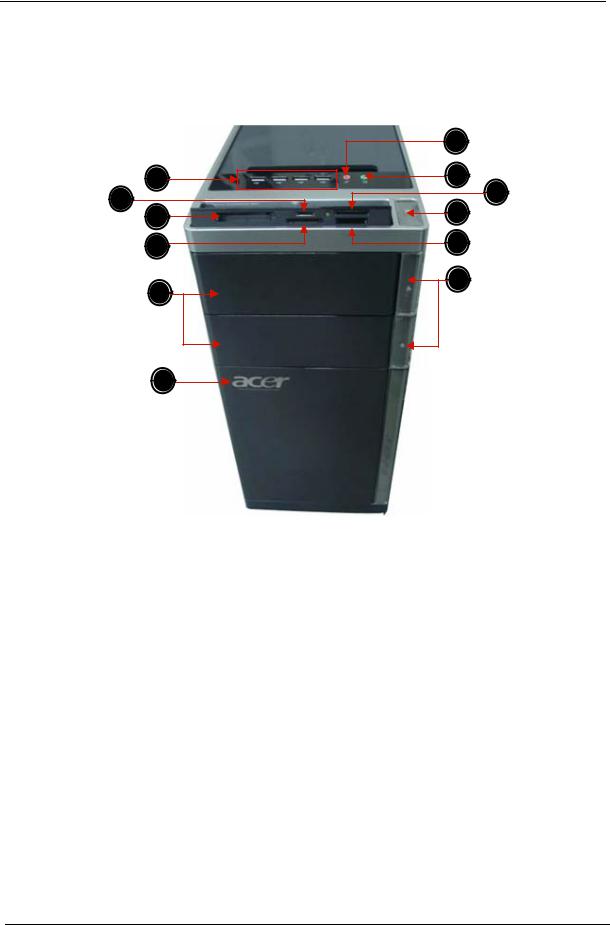
System Components
This section is a virtual tour of the system’s interior and exterior components.
Front Panel
|
12 |
|
1 |
11 |
|
2 |
10 |
|
9 |
||
3 |
||
4 |
8 |
|
5 |
7 |
|
|
6
No. |
Component |
|
|
1 |
USB 2.0 ports |
|
|
2 |
Micro SD/M2 slot |
|
|
3 |
CF I/II (CompactFlash Type I/II) slot |
|
|
4 |
XD(XD-PICTURE) slot |
|
|
5 |
Optical drive |
|
|
6 |
Acer logo |
|
|
7 |
Optical drive button |
|
|
8 |
SD(Secure Digital) solt |
|
|
9 |
Power button |
|
|
10 |
Memory stick PRO slot |
|
|
11 |
Headphone/Speaker-out/line-out jack |
|
|
12 |
Microphone-in jack |
|
|
6 |
Chapter 1 |
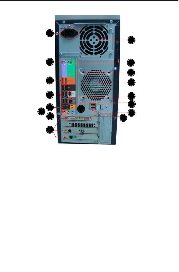
Rear Panel
1
17
2 |
16 |
|
|
15 |
|
3 |
14 |
|
|
||
4 |
13 |
|
5 |
12 |
|
9 |
||
6 |
||
11 |
||
7 |
10 |
|
|
||
8 |
|
No. |
Component |
|
|
1 |
Power connector |
|
|
2 |
PS2 mouse port Line-out jack |
|
|
3 |
eSATA port |
|
|
4 |
USB 2.0 ports |
|
|
5 |
S/PDIF port |
|
|
6 |
Microphone/speaker-out/line-in jack |
|
|
7 |
Line-out jack |
|
|
8 |
Expansion slot (graphics card and TV tuner card and Mode card) |
|
|
9 |
Surround rear L/R |
|
|
10 |
Line-in jack |
|
|
11 |
USB 2.0 ports |
|
|
12 |
Center speaker/subwoofer jack |
|
|
13 |
LAN connector |
|
|
14 |
System FAN |
|
|
15 |
1394 port |
|
|
16 |
PS2 keyboard port |
|
|
17 |
Fan aperture |
|
|
Chapter 1 |
7 |

Power Management Function(ACPI support function)
Device Standby Mode
•Independent power management timer for hard disk drive devices(0-15 minutes,time step=1minute).
•Hard Disk drive goes into Standby mode(for ATA standard interface).
•Disable V-sync to control the VESA DPMS monitor.
•Resume method:device activated (keyboard for DOS, keyboard &mouse for Windows.
•Resume recovery time 3-5sec
Global Standby Mode
•Global power management timer(2-120minutes,time step=10minute).
•Hard disk drive goes into Standby mode(for ATA standard interface).
•Disable H-sync and V-sync signals to control the VESA DPMS monitor.
•Resume method: Resume to original state by pushing external switch Button,modem ring in,keyboard an mouse for APM mode.
•Resume recovery time :7-10sec
Suspend Mode
•Independent power management timer(2-120minutes,time step=10minute)or pushing extern switch button.
•CPU goes into SMM
•CPU asserts STPCLK# and goes into the Stop Grant State.
•LED on panel turns amber colour.
•Hard disk drive goes into SLEEP mode (for ATA standard interface).
•Disable H-sync and V-sync signals to control the VESA DPMS monitor.
•Ultra I/O and VGA chip go into power saving mode.
•Resume method: Resume to original state by pushing external switch Button,modem ring in,keyboard an mouse for APM mode
•Return to original state by pushing external switch button,modem ring in and USB keyboard for ACPI mode.
ACPI
•ACPI specification 1.0b
•S0,S1,S2 and S5 sleep state support.
•On board device power management support.
•On board device configuration support.
8 |
Chapter 1 |

Chapter 2
System Utilities
CMOS Setup Utility
CMOS setup is a hardware configuration program built into the system ROM, called the complementary metaloxide semiconductor (CMOS) Setup Utility. Since most systems are already properly configured and optimized, there is no need to run this utility. You will need to run this utility under the following conditions.
q When changing the system configuration settings
q When redefining the communication ports to prevent any conflicts q When modifying the power management configuration
q When changing the password or making other changes to the security setup
qWhen a configuration error is detected by the system and you are prompted ("Run Setup" message) to make changes to the CMOS setup
NOTE: If you repeatedly receive Run Setup messages, the battery may be bad. In this case, the system cannot retain configuration values in CMOS. Ask a qualified technician for assistance.
CMOS setup loads the configuration values in a battery-backed nonvolatile memory called CMOS RAM. This memory area is not part of the system RAM which allows configuration data to be retained when power is turned off.
Before you run the CMOS Setup Utility, make sure that you have saved all open files. The system reboots immediately after you close the Setup.
NOTE: CMOS Setup Utility will be simply referred to as “BIOS”, "Setup", or "Setup utility" in this guide.
The screenshots used in this guide display default system values. These values may not be the same those found in your system.
Chapter 2 |
9 |

Entering CMOS setup
1.Turn on the server and the monitor.
If the server is already turned on, close all open applications, then restart the server.
2.During POST, press Delete.
If you fail to press Delete before POST is completed, you will need to restart the server.
The Setup Main menu will be displayed showing the Setup’s menu bar. Use the left and right arrow keys to move between selections on the menu bar.
Navigating Through the Setup Utility
Use the following keys to move around the Setup utility.
q Left and Right arrow keys – Move between selections on the menu bar. q Up and Down arrow keys – Move the cursor to the field you want.
q PgUp and PgDn keys – Move the cursor to the previous and next page of a multiple page menu. q Home – Move the cursor to the first page of a multiple page menu.
q End – Move the cursor to the last page of a multiple page menu.
q+ and - keys – Select a value for the currently selected field (only if it is user-configurable). Press these keys repeatedly to display each possible entry, or the Enter key to choose from a pop-up menu.
NOTE: Grayed-out fields are not user-configurable.
q Enter key – Display a submenu screen. NOTE: Availability of submenu screen is indicated by a (>).
qEsc – If you press this key:
q On one of the primary menu screens, the Exit menu displays. q On a submenu screen, the previous screen displays.
qWhen you are making selections from a pop-up menu, closes the pop-up without making a selection.
q F1 – Display the General Help panel.
q F6 – Press to load optimized default system values. q F7 – Press to load fail-safe default system values.
q F10 – Save changes made the Setup and close the utility.
10 |
Chapter 2 |
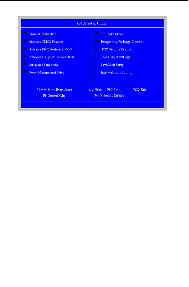
Setup Utility Menus
The Setup Main menu includes the following main setup categories.
Parameter |
Description |
|
|
Product Information |
This page shows the relevant information of the main board |
|
|
Standard CMOS Features |
This setup page includes all the items in standard compatible BIOS |
|
|
Advanced Chipset Features |
This setup page includes all the items of Award special enhanced features |
|
|
Advanced Chipset Features |
This setup page includes all advanced chipset features |
|
|
Integrated Peripherals |
This setup page includes all onboard peripherals |
|
|
Power Management Setup |
This setup page includes all the items of Green function features |
|
|
PC Health Status |
This setup page is the System auto detect Temperature, voltage, and fan speed |
|
|
Frequency/Voltage Control |
This setup page is the System Frequency setup |
|
|
BIOS Security Features |
Change, set or disable password. It allows you to limit access to the System |
|
|
Load Default Setting |
Load Default Setting indicates the value of the system parameters which the system would be |
|
in best performance configuration |
|
|
Save & Exit Setup |
Save CMOS value settings to CMOS and exit setup |
|
|
Exit Without Saving |
Abandon all CMOS value changes and exit setup |
|
|
In the descriptive table following each of the menu screenshots, settings in boldface are the default and suggested settings.
Chapter 2 |
11 |
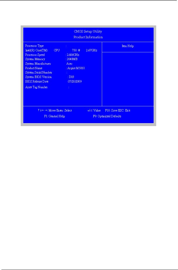
Product Information
The Product Information menu displays basic information about the system. These entries are for your reference only and are not user-configurable.
Parameter |
Description |
|
|
Processor Type |
Type of CPU installed on the system. |
|
|
Processor Speed |
Speed of the CPU installed on the system. |
|
|
System Memory |
Total size of system memory installed on the system. |
|
|
System Manufacturer |
Name of the manufacturer of this system. |
|
|
Product Name |
Product name of the system. |
|
|
System Serial Number |
Serial number of the system. |
|
|
System BIOS Version |
Version number of the BIOS setup utility. |
|
|
BIOS Release Date |
Date when the BIOS setup utility was released |
|
|
Asset Tag Number |
Asset tag number of this system. |
|
|
12 |
Chapter 2 |

Standard CMOS Features
Parameter |
Description |
Option |
|
|
|
System Date |
Set the date following the weekday-month-day-year format. |
|
|
|
|
System Time |
Set the system time following the hour-minute-second format. |
|
|
|
|
AHCI Port 1/2/3/5/6 |
Press Enter to view detailed device information. |
|
|
|
|
Halt On |
Determines whether the system will stop for an error during the POST. |
All, But Keyboard |
|
|
No Errors |
|
|
All Errors |
|
|
|
Chapter 2 |
13 |
Advanced BIOS Feature
Parameter |
Description |
Option |
|
|
|
Quick Boot |
Allows you to decrease the time it takes to boot the computer by shortening |
Enabled |
|
or skipping certain standard booting process. |
Disabled |
|
|
|
Quiet Boot |
When enabled, the BIOS splash screen displays during startup. |
Enabled |
|
When disabled, the diagnostic screen displays during startup. |
Disabled |
|
|
|
1st/2nd/3rd/4th Boot Device |
Specifies the boot order from the available devices. |
Hard Disk |
|
|
CD^DVD |
|
|
Removable |
|
|
Device |
|
|
LAN |
|
|
|
Hard Disk Drive |
Press Enter to access the Hard Disk Drive Priority submenu and specify the boot device |
|
|
priority sequence from available hard drives. |
|
|
|
|
Removable Device |
Press Enter to access the Removable Device Priority submenu and specify the boot device |
|
|
priority sequence from available removable drives. |
|
|
|
|
CD/DVD Drives |
Press Enter to access the Optical Disk Drive Priority submenu and specify the boot device |
|
|
priority sequence from available CD/DVD drives. |
|
|
|
|
Bootup Num-Lock |
Selects power on state for Num Lock. |
On |
|
|
Off |
|
|
|
USB Beep Message |
Enables or disables BIOS to display error beeps or messages during USB |
Disabled |
|
device enumeration. |
Enabled |
|
|
|
14 |
Chapter 2 |
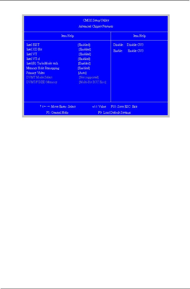
Advanced Chipset Features
Parameter |
Description |
Option |
|
|
|
Intel EIST |
When enabled, this feature allows the OS to reduce power consumption. |
Enabled |
|
When disabled, the system operates at maximum CPU speed. |
Disabled |
|
|
|
Intel XD Bit |
When enabled, the processor disables code execution when a worm |
Enabled |
|
attempts to insert a code in the buffer preventing damage and worm |
Disabled |
|
propagation. |
|
|
When disabled, the processor forces the Execute Disable (XD) Bit feature |
|
|
flag to always return to 0. |
|
|
|
|
Intel VT |
Enables or disables the Virtualization Technology (VT) availability. If |
Enabled |
|
enabled, a virtual machine manager (VMM) can utilize the additional |
Disabled |
|
hardware virtualization capabilities provided by this technology. |
|
|
Note: A full reset is required to change the setting. |
|
|
|
|
Intel VT-d |
For Intel platform |
Enabled |
|
|
Disabled |
|
|
|
Memory Hole Remapping |
Enables or disables remapping of overlapped PCI memory above the total |
Enabled |
|
physical memory. |
Disabled |
|
|
|
Primary Video |
Select a graphic controller as a primary boot device. |
Auto |
|
|
PCIE |
|
|
Onboard VGA |
|
|
|
DVMT Mode Select |
You can choose the Fixed Mode or DVMT Mode. |
Not supported |
|
|
|
DVMT/Fixed Memory |
The setting is only available for WinXp. |
|
|
|
|
Chapter 2 |
15 |

Integrated Peripherals
Parameter |
Description |
Option |
|
|
|
Onboard ESATA Controller |
Enables or disables the onboard ESATA controller. |
Enabled |
|
|
Disabled |
|
|
|
Onboard SATA Controller |
Enables or disables the onboard SATA controller. |
Enabled |
|
|
Disabled |
|
|
|
Onboard SATA Mode |
Select an operating mode for the onboard SATA. |
RAID |
|
|
Native IDE |
|
|
|
Onboard USB Controller |
Enables or disables the onboard USB controller. |
Enabled |
|
|
Disabled |
|
|
|
Legacy USB Support |
Enables or disables support for legacy USB devices. |
Enabled |
|
|
Disabled |
|
|
|
Onboard Audio Controller |
Enables or disables the onboard audio controller. |
Enabled |
|
|
Disabled |
|
|
|
Onboard LAN Controller |
Enables or disables the onboard LAN controller. |
Enabled |
|
|
Disabled |
|
|
|
Onboard LAN Option ROM |
Enables or disables the load of embedded option ROM for onboard |
Enabled |
|
network controller. |
Disabled |
|
|
|
16 |
Chapter 2 |
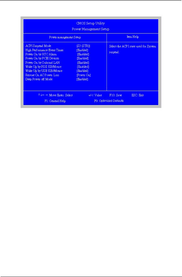
Power Management Setup
Parameter |
Description |
Option |
|
|
|
ACPI Suspend Mode |
Select an ACPI state. |
S3 (STR) |
|
|
S1 (POS) |
|
|
|
High Performance Event |
Enables or disables High Performance Event Timer |
Enabled |
Timer |
|
Disabled |
|
|
|
Power On by RTC Alarm |
Enables or Disables to wake up the system by RTC Alarm Function |
Enabled |
|
|
Disabled |
|
|
|
Power On by PCIE Devices |
Enables or disables to wake up the system from a power saving mode |
Enabled |
|
through an event on PCI Express device. |
Disabled |
|
|
|
Power On by Onboard Lan |
Enables or Disables to wake up the system by Onboard Lan function |
Enabled |
|
|
Disabled |
|
|
|
Wake Up by PS/2 KB/ |
Enables or disables to wake up the system from a power saving mode |
Enabled |
Mouse |
using a PS2 keyboard or mouse. |
Disabled |
|
|
|
Wake Up by USB KB/ |
If enabled, press any key or click the mouse will wake system from S1/ |
Enabled |
Mouse |
S3 state. |
Disabled |
|
|
|
Restore On AC Power Loss |
Enables or disables the system to reboot after a power failure or |
Power Off |
|
interrupt occurs. |
Power On |
|
|
Last State |
|
|
|
Deep power off mode |
Select the Deep power off Mode |
Enabled |
|
|
Disabled |
|
|
|
Chapter 2 |
17 |
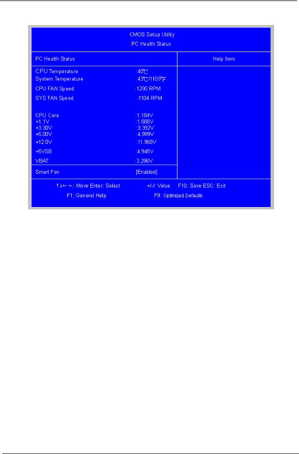
PC Health Status
Parameter |
Description |
Option |
|
|
|
Smart FAN |
Enables or disables the smart system fan control function. |
Enabled |
|
|
Disabled |
|
|
|
18 |
Chapter 2 |
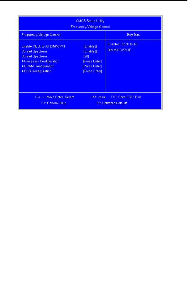
Frequency/Voltage Control
Parameter |
Description |
Option |
|
|
|
Spread Spectrum |
Enables or disables the reduction of the mainboard’s EMI. |
Enabled |
|
Note: Remember to disable the Spread Spectrum feature if you are |
Disabled |
|
overclocking. A slight jitter can introduce a temporary boost in clock |
|
|
speed causing the overclocked processor to lock up. |
|
|
|
|
Chapter 2 |
19 |
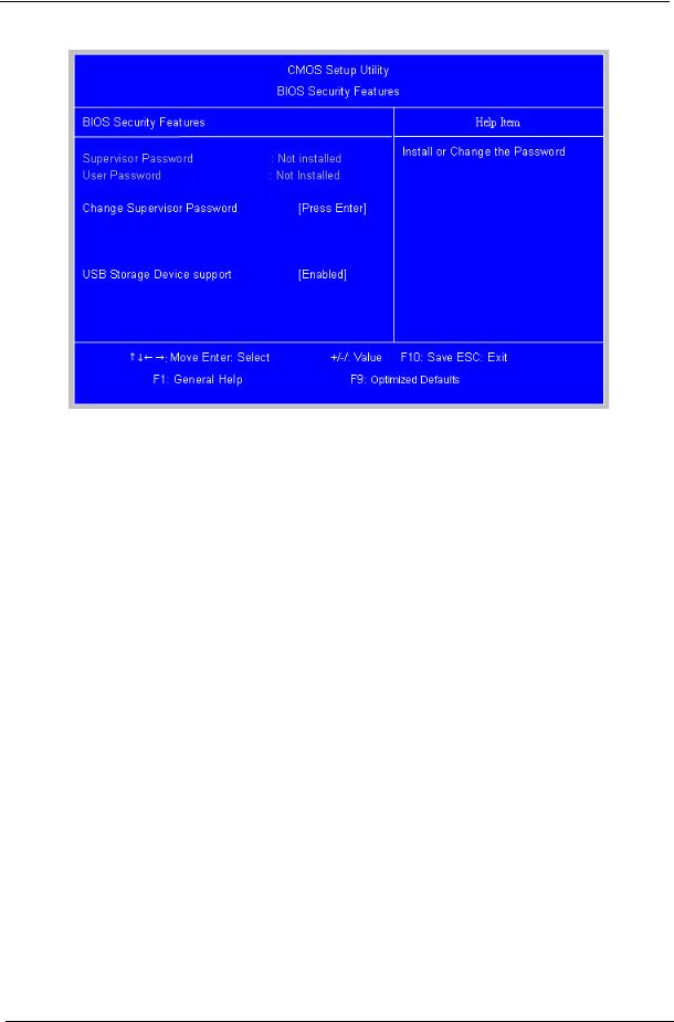
BIOS Security Features
Parameter |
Description |
|
|
Supervisor Password |
Indicates the status of the supervisor password. |
|
|
User Password |
Indicates the status of the user password. |
|
|
Change Supervisor |
Supervisor password prevents unauthorized access to the BIOS Setup Utility. |
Password |
Press Enter to change the Supervisor password. |
|
|
Setting a supervisor password
1.Use the up/down arrow keys to select Change Supervisor Password menu then press Enter. A password box will appear.
2.Type a password then press Enter.
The password may consist up to six alphanumeric characters (A-Z, a-z, 0-9)
3.Retype the password to verify the first entry then press Enter again.
4.Press F10.
5.Select Yes to save the new password and close the Setup Utility.
Changing the supervisor password
1.Use the up/down arrow keys to select Change Supervisor Password menu then press Enter.
2.Type the original password then press Enter.
3.Type a new password then press Enter.
4.Retype the password to verify the first entry then press Enter again.
5.Press F10.
6.Select Yes to save the new password and close the Setup Utility.
Removing a supervisor password
1.Use the up/down arrow keys to select Change Supervisor Password menu then press Enter.
2.Enter the current password then press Enter.
3.Press Enter twice without entering anything in the password fields.
20 |
Chapter 2 |
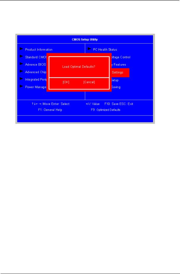
Load Default Settings
The Load Default Settings menu allows you to load the default settings for all BIOS setup parameters. Setup defaults are quite demanding in terms of resources consumption. If you are using low-speed memory chips or other kinds of low-performance components and you choose to load these settings, the system might not function properly.
Chapter 2 |
21 |
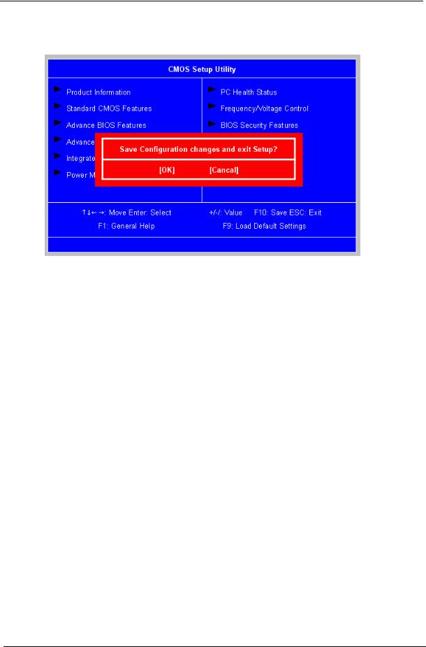
Save & Exit Setup
The Save & Exit Setup menu allows you to save changes made and close the Setup Utility.
22 |
Chapter 2 |
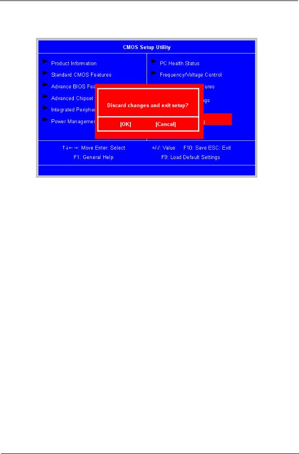
Exit Without Saving
The Exit Without Saving menu allows you to discard changes made and close the Setup Utility.
Chapter 2 |
23 |
Loading...