


 Loading...
3M Personal Safety Division
3MTM SoundPro SE/DL Series Sound Level Meters
SoundPro User Manual
3MTM SoundPro Sound Level Meter
Dangers, Warnings, Cautions & Battery
Danger!
Failure to observe the following procedures may result in serious personal injury
•Not for use in explosive or hazardous locations. This product is not intrinsically safe.
Warning!
Failure to observe the following procedures could damage the instrument
•Read the manual before operation.
•Do not store in temperatures exceeding 60°C (140°F).
•Do not immerse in liquids.
•Condensation may damage your instrument.
•Substitution of components may impair the accuracy of the instrument. Repair should be performed by authorized service personnel only.
Caution!
General
•The battery in this instrument has limited shelf-life, even if never used.
•A non-condensing environment is required for proper measurements.
Intended Use:
The SoundPro is intended to measure sound pressure levels in air. Consult your company’s safety professional for local standards, or call 3M at 1-800-243-4630.
Models SE and DL

ii Table of Contents |
|
TABLE OF CONTENTS |
|
Introduction .............................................................................................................. |
1 |
Models and options.................................................................................................. |
1 |
Frequency resolution............................................................................................... |
2 |
Octave bands.......................................................................................................................... |
2 |
Third -octave bands ................................................................................................................ |
3 |
Naming bands......................................................................................................................... |
3 |
Analysis type........................................................................................................................... |
5 |
Logging explained.................................................................................................... |
5 |
Physical Characteristics.......................................................................................... |
5 |
The Display ............................................................................................................................. |
5 |
Hardware interfaces................................................................................................................ |
6 |
Memory card slot ............................................................................................................... |
6 |
USB port ............................................................................................................................ |
6 |
AC/DC port ........................................................................................................................ |
7 |
Power jack ......................................................................................................................... |
7 |
Auxiliary port...................................................................................................................... |
7 |
Information screen................................................................................................... |
8 |
Screen contents ...................................................................................................................... |
8 |
Detection Management Software DMS ................................................................... |
9 |
DMS Start Page ...................................................................................................................... |
9 |
Getting Started ....................................................................................................... |
11 |
Checking the equipment........................................................................................ |
11 |
Installing the preamp............................................................................................................. |
12 |
Microphone and accessories ................................................................................ |
12 |
Class/Type 1 and Class/Type 2 instrument .......................................................................... |
13 |
Windscreen...................................................................................................................... |
13 |
Providing power ..................................................................................................... |
14 |
Installing Batteries................................................................................................................. |
14 |
Battery power explained ....................................................................................................... |
15 |
|
Models SE and DL |

iii |
Table of Contents |
|
Checking or changing type .................................................................................................. |
15 |
|
Using power supply or auto adapter ..................................................................................... |
17 |
|
Turning on .............................................................................................................. |
18 |
|
Start screen and the keypad................................................................................................. |
18 |
|
SoundPro functionality.......................................................................................... |
19 |
|
The keypad explained........................................................................................................... |
19 |
|
Indicators explained .............................................................................................................. |
20 |
|
Navigating ............................................................................................................................. |
21 |
|
Turning off .............................................................................................................. |
21 |
|
Basic setups........................................................................................................... |
23 |
|
Changing microphone settings ............................................................................................. |
24 |
|
Time and date ....................................................................................................................... |
25 |
|
Measurement type (SLM, 1/1, 1/3, STI-PA, RT60)............................................................... |
26 |
|
Meter 1/Meter 2 Parameters (i.e. response time, weighting)................................................ |
27 |
|
Measurement setup (for community noise) .......................................................................... |
28 |
|
|
C-A measurement settings.............................................................................................. |
30 |
Logging................................................................................................................... |
31 |
|
Logging options..................................................................................................................... |
31 |
|
Exceedance level.................................................................................................................. |
31 |
|
Filters .................................................................................................................................... |
31 |
|
Logging interval..................................................................................................................... |
31 |
|
Setting logging options.......................................................................................................... |
32 |
|
Setting up display options..................................................................................... |
33 |
|
Language .............................................................................................................................. |
34 |
|
Backlight................................................................................................................................ |
35 |
|
Contrast................................................................................................................................. |
36 |
|
Advanced setups ................................................................................................... |
37 |
|
Auto-Run................................................................................................................. |
38 |
|
Models SE and DL

iv |
Table of Contents |
|
Setting up auto-run ................................................................................................ |
38 |
|
Date setting........................................................................................................................... |
38 |
|
Days of week setting............................................................................................................. |
40 |
|
Auto-run shutdown screen .................................................................................................... |
42 |
|
|
Auto-run shutdown screen explained.............................................................................. |
42 |
Timed run setting .................................................................................................................. |
43 |
|
Level-triggered auto-on setting ............................................................................................. |
44 |
|
Locking setup or run mode ................................................................................... |
46 |
|
Setting secure run or secure setup (locking) ........................................................................ |
46 |
|
|
About Secure Run ........................................................................................................... |
46 |
|
About Secure Setup ........................................................................................................ |
46 |
Disabling secure run or secure setup (unlocking)................................................................. |
49 |
|
|
Secure code backup number .......................................................................................... |
49 |
Digital outputs/Triggering...................................................................................... |
50 |
|
Tracking runs ........................................................................................................................ |
50 |
|
Digital outputs and SPL ........................................................................................................ |
51 |
|
Communications .................................................................................................... |
51 |
|
QSP/Serial ............................................................................................................................ |
52 |
|
Mass Storage........................................................................................................................ |
52 |
|
Viewing real-time measurements remotely........................................................................... |
53 |
|
GPS....................................................................................................................................... |
54 |
|
|
GPS display..................................................................................................................... |
54 |
|
GPS explained................................................................................................................. |
54 |
Preparing to measure & running........................................................................... |
57 |
|
Virtual meters ......................................................................................................... |
57 |
|
Meter 1/Meter 2 explained .................................................................................................... |
57 |
|
Measurement notation (IEC/ISO)........................................................................... |
57 |
|
Overview of running a session/study ................................................................... |
58 |
|
Preparing to measure ............................................................................................ |
59 |
|
Sessions and Studies ........................................................................................................... |
59 |
|
|
|
Models SE and DL |

v |
Table of Contents |
|
Measurement range.............................................................................................................. |
60 |
|
Calibrate.................................................................................................................. |
61 |
|
Calibration screen ................................................................................................................. |
61 |
|
|
Pre-Calibration................................................................................................................. |
61 |
|
Post-Calibration ............................................................................................................... |
61 |
Performing a calibration ........................................................................................................ |
62 |
|
Running a session/study....................................................................................... |
64 |
|
Measurement navigation ....................................................................................... |
65 |
|
Using softkeys in measurement screens .............................................................................. |
65 |
|
|
Changing displayed measurement.................................................................................. |
66 |
|
Analysis type, time response and weighting ................................................................... |
66 |
Measurement screen icons ................................................................................... |
67 |
|
Descriptor types .................................................................................................................... |
67 |
|
Measurement screens............................................................................................ |
68 |
|
Bar Chart and Filtered Bar Chart .......................................................................................... |
68 |
|
Community Noise screen...................................................................................................... |
69 |
|
Dosimetry screen .................................................................................................................. |
70 |
|
|
Dosimetry measurements ............................................................................................... |
70 |
Tabulation screens................................................................................................................ |
71 |
|
|
1/1 and 1/3 octave analysis measurement results .................................................................... |
71 |
Time History/Back-erase screen ........................................................................... |
72 |
|
Back-erasing........................................................................................................... |
72 |
|
Results of back-erasing ........................................................................................................ |
73 |
|
Stopping a session................................................................................................................ |
75 |
|
|
Stopping and pausing...................................................................................................... |
75 |
RT60, Curves, and STI-PA ..................................................................................... |
77 |
|
Additional options.................................................................................................. |
77 |
|
Reverberation........................................................................................................................ |
77 |
|
Reverberation time (RT60) ................................................................................................... |
78 |
|
Reverberation (RT60) methods ............................................................................................ |
78 |
|
|
Interrupted noise.............................................................................................................. |
79 |
|
|
Models SE and DL |

vi |
Table of Contents |
|
|
Impulse noise .................................................................................................................. |
79 |
Reverberation options........................................................................................................... |
80 |
|
Setting up reverberation........................................................................................................ |
81 |
|
Running reverberation test.................................................................................................... |
82 |
|
Reverberation results............................................................................................................ |
83 |
|
|
RT60 summary screen .................................................................................................... |
84 |
|
Viewing RT60 values of each band................................................................................. |
84 |
|
Deleting RT60 value in a filtered band ............................................................................ |
84 |
|
Decay curve screen......................................................................................................... |
85 |
|
Tabular RT60 screen....................................................................................................... |
86 |
Curves..................................................................................................................... |
87 |
|
Captured curves..................................................................................................... |
87 |
|
Captured curve applications ................................................................................................. |
87 |
|
Setting up captured curves ................................................................................................... |
88 |
|
Running captured curves ...................................................................................................... |
90 |
|
Criterion curve families ......................................................................................... |
91 |
|
Types of Criterion Curves ..................................................................................................... |
91 |
|
Setting up criterion curves .................................................................................................... |
92 |
|
Audiometric background curves........................................................................... |
94 |
|
Setting up audiometric background curves........................................................................... |
94 |
|
Running and viewing curves................................................................................. |
96 |
|
Curve measurements and results......................................................................................... |
96 |
|
Speech Intelligibility............................................................................................... |
98 |
|
STI-PA testing....................................................................................................................... |
98 |
|
Zones .................................................................................................................................... |
98 |
|
Selecting STI scale or CIS scale .......................................................................................... |
98 |
|
|
STI scale.......................................................................................................................... |
99 |
|
Common Intelligibility Scale (CIS) ................................................................................... |
99 |
|
When to take STI-PA readings?...................................................................................... |
99 |
Conducting a STI-PA test (overview of steps) .................................................................... |
100 |
|
STI-PA setup....................................................................................................................... |
100 |
|
|
|
Models SE and DL |

vii |
Table of Contents |
|
Conducting a level setup (for STI-PA) ................................................................................ |
103 |
|
Running a speech intelligibility study .................................................................................. |
103 |
|
STI-PA results screens ....................................................................................................... |
104 |
|
|
STI-PA measurement and scale results screen............................................................ |
104 |
|
STI-PA modulation screen ............................................................................................ |
105 |
|
STI-PA modulation envelope screen............................................................................. |
106 |
Applying captured curves for STI-PA testing ...................................................................... |
108 |
|
Viewing Past Measurements ............................................................................... |
111 |
|
Files |
....................................................................................................................... |
111 |
File directories...................................................................................................... |
111 |
|
File directory screen explained ........................................................................................... |
112 |
|
Viewing past sessions/studies (review mode) .................................................................... |
112 |
|
Loading and deleting files ................................................................................................... |
115 |
|
Session directory ................................................................................................................ |
116 |
|
|
Navigating in a session/config. directory....................................................................... |
117 |
|
Naming and renaming files............................................................................................ |
117 |
Configuration directory ....................................................................................... |
118 |
|
Saving (& naming) setup file (config. file) ........................................................................... |
118 |
|
Viewing, loading, deleting setup files (config.).................................................................... |
119 |
|
Memory card......................................................................................................... |
120 |
|
Compatibility........................................................................................................................ |
120 |
|
Formatting a card with the SoundPro ................................................................................. |
120 |
|
Communicating.................................................................................................... |
121 |
|
Communicating with a PC ................................................................................... |
121 |
|
Using Detection Management Software DMS .................................................................... |
121 |
|
|
Using an external card reader ....................................................................................... |
121 |
Working with measurement data in DMS ........................................................................... |
121 |
|
DMS and working with SoundPro data ............................................................................... |
122 |
|
AC/DC output........................................................................................................ |
123 |
|
AC output ............................................................................................................................ |
123 |
|
|
|
Models SE and DL |

viii |
Table of Contents |
|
DC output ............................................................................................................................ |
123 |
|
Specifications....................................................................................................... |
125 |
|
Conformance to standards.................................................................................. |
125 |
|
|
Acoustics ....................................................................................................................... |
125 |
|
EMC emissions and immunity ....................................................................................... |
125 |
Mechanical characteristics.................................................................................. |
125 |
|
Electrical characteristics ..................................................................................... |
126 |
|
|
Power sources............................................................................................................... |
126 |
|
Internal power ......................................................................................................................... |
126 |
|
External power ........................................................................................................................ |
127 |
|
Preamplifier (removable) ............................................................................................... |
127 |
|
Meters............................................................................................................................ |
127 |
|
Bandwidth...................................................................................................................... |
127 |
|
Octave filters (optional) ................................................................................................. |
128 |
|
Third-octave filters (optional)......................................................................................... |
128 |
|
Instrument noise ............................................................................................................ |
128 |
Environmental effects.......................................................................................... |
128 |
|
|
Temperature .................................................................................................................. |
128 |
|
Humidity......................................................................................................................... |
129 |
User interface ....................................................................................................... |
129 |
|
|
Display........................................................................................................................... |
129 |
|
Keypad .......................................................................................................................... |
129 |
|
Languages..................................................................................................................... |
129 |
Input/output .......................................................................................................... |
129 |
|
|
Microphones .................................................................................................................. |
129 |
|
AC/DC outputs............................................................................................................... |
130 |
|
Communications ports................................................................................................... |
131 |
Measurements...................................................................................................... |
131 |
|
|
Types............................................................................................................................. |
131 |
|
Ranges .......................................................................................................................... |
131 |
|
Measurement parameters ............................................................................................. |
131 |
|
Other.............................................................................................................................. |
132 |
Calibration ............................................................................................................ |
132 |
|
Studies and sessions........................................................................................... |
132 |
|
Special features.................................................................................................... |
132 |
|
|
Security.......................................................................................................................... |
132 |
|
Back-erase .................................................................................................................... |
133 |
|
|
Models SE and DL |

ix |
Table of Contents |
|
|
Logging (optional)................................................................................................ |
133 |
||
Part numbers........................................................................................................ |
133 |
||
|
Replacement parts ........................................................................................................ |
133 |
|
|
Optional parts ................................................................................................................ |
134 |
|
Port pinouts.......................................................................................................... |
135 |
||
AC/DC jack |
.......................................................................................................................... |
135 |
|
Auxiliary connector.............................................................................................................. |
135 |
||
Block Diagram ..............................................................................for SoundPro |
136 |
||
Glossary of ................................................................................................Terms |
137 |
||
Customer service ................................................................................................. |
149 |
||
Contacting 3M ...................................................................................................... |
149 |
||
Warranty ............................................................................................................... |
|
150 |
|
FIGURES |
|
|
|
Figure 1-1: ........................................... |
SoundPro Models SE and DL and Option 1 and Option 2 |
1 |
|
Figure 1-2: .................................................................................................................. |
Octave bands |
2 |
|
Figure 1-3: ........................................................................................................ |
Third Octave bands |
3 |
|
Figure 1-4: ............................................................................................... |
Hardware Interface Panel |
6 |
|
Figure 1-5: .......................................................................................... |
The Unit Information screen |
8 |
|
Figure 2-1: ...................................................................................... |
Identify SoundPro equipment |
11 |
|
Figure 2-2: ..................................................................................................... |
SoundPro & Preamp |
12 |
|
Figure 2-3: ............................................................. |
SoundPro with microphone and windscreen |
13 |
|
Figure 2-4: ........................................................................................................ |
Installing batteries |
14 |
|
Figure 2-5: ................................................................................................... |
Battery check screen |
15 |
|
Figure 2-6: ............................................................................ |
Selecting Setup in the Start Screen |
16 |
|
Figure 2-7: .......................................................... |
Selecting battery type in battery check screen |
16 |
|
Figure 2-8: ................................................ |
Attaching the charger adapter with the plug adapter |
17 |
|
Figure 2-9: .................................................................................... |
Base (or bottom) of SoundPro |
17 |
|
Figure 2-10: ................................................................. |
SoundPro SE/DL start screen and keypad |
18 |
|
Figure 3-1: ................................................................ |
Microphone Settings (Signal Input screen) |
24 |
|
Figure 3-2: ................................................................................................ |
Time and Date Settings |
25 |
|
Figure 3-3: ........................................................................... |
Measurement type and start screen |
26 |
|
Figure 3-4: .................................................................................. |
Meter 1 and Meter 2 parameters |
27 |
|
Figure 3-5: ........................................................ |
Measures screen for community noise settings |
28 |
|
Figure 3-6: .................................................. |
C - A measurement settings for Meter 1 and Meter 2 |
30 |
|
Figure 3-7: ........................................................................................ |
Logged Data Chart example |
31 |
|
Figure 3-8: ........................................................................................... |
Logging screen explained |
32 |
|
Figure 3-9: .................................................................................................... |
Display setup screen |
33 |
|
Figure 3-10: .......................................................................................................... |
Language screen |
34 |
|
Figure 3-11: ........................................................................................................... |
Backlight setting |
35 |
|
Figure 4-1: ....................................................................................... |
Auto - Run with Date selected |
38 |
|
|
|
|
Models SE and DL |
x |
Table of Contents |
|
|
Figure 4-2: |
Setting Date parameters for Auto-Run #1 .................................................................. |
39 |
|
Figure 4-3: |
Example of setting up Auto-Run (QSP-II)................................................................... |
40 |
|
Figure 4-4: |
Day of the Week (DOW) setup ..................................................................................... |
41 |
|
Figure 4-5: |
Auto-Run Shutdown screen ........................................................................................ |
42 |
|
Figure 4-6: |
Timed Run setup screen.............................................................................................. |
43 |
|
Figure 4-7: |
Level-Triggered screen ................................................................................................ |
44 |
|
Figure 4-8: |
Secure/Lock option ...................................................................................................... |
47 |
|
Figure 4-9: |
Secure/Lock screen...................................................................................................... |
47 |
|
Figure 4-10: |
Adding code for secure/lock screen........................................................................... |
48 |
|
Figure 4-11: |
Secure/lock run prompt ............................................................................................... |
48 |
|
Figure 4-12: |
Secure/lock setup prompt............................................................................................ |
49 |
|
Figure 4-13: |
Digital-Out screen......................................................................................................... |
50 |
|
Figure 4-14: |
QSP/Serial ..................................................................................................................... |
52 |
|
Figure 4-15: |
Mass Storage ................................................................................................................ |
52 |
|
Figure 4-16: |
Log to Port .................................................................................................................... |
53 |
|
Figure 4-17: |
Comm-Set screen for GPS data .................................................................................. |
54 |
|
Figure 4-18: |
Viewing GPS coordinates in COMM-Set screen ........................................................ |
55 |
|
Figure 5-1: |
Bar chart screen (A) and Filtered Bar Chart (B)......................................................... |
60 |
|
Figure 5-2: |
Attaching calibrator to SoundPro ............................................................................... |
62 |
|
Figure 5-3: |
Setting pre-cal screen .................................................................................................. |
63 |
|
Figure 5-4: |
Calibration history screen ........................................................................................... |
63 |
|
Figure 5-5: |
Post-Calibrate history screen...................................................................................... |
64 |
|
Figure 5-6: |
Bar Chart screen in run mode ..................................................................................... |
64 |
|
Figure 5-7: |
Selecting measurements with Lookup softkey.......................................................... |
66 |
|
Figure 5-8: |
Example measurement icons & descriptors .............................................................. |
67 |
|
Figure 5-9: |
Bar Chart screen and Filtered Bar Chart screen........................................................ |
68 |
|
Figure 5-10: |
Community Noise screen............................................................................................. |
69 |
|
Figure 5-11: |
Dosimetry screen ......................................................................................................... |
70 |
|
Figure 5-12: |
Tabulation screen for octave filtering......................................................................... |
71 |
|
Figure 5-13: |
Back-erasing................................................................................................................. |
72 |
|
Figure 5-14: |
Time Log screen........................................................................................................... |
74 |
|
Figure 5-15: |
Stopping and pausing.................................................................................................. |
75 |
|
Figure 6-1: |
Reverb Time.................................................................................................................. |
78 |
|
Figure 6-2: |
Interrupted noise example........................................................................................... |
79 |
|
Figure 6-3: |
Reverb Time Setup screen........................................................................................... |
81 |
|
Figure 6-4: |
Reverb Time Setup screen........................................................................................... |
83 |
|
Figure 6-5: |
RT60 bar chart screen.................................................................................................. |
84 |
|
Figure 6-6: |
Decay curve screen...................................................................................................... |
85 |
|
Figure 6-7: |
Tabular octave filtering RT screen.............................................................................. |
86 |
|
Figure 6-8: |
Selecting measurement type for curves..................................................................... |
88 |
|
Figure 6-9: |
Captured Curves and Survey mode............................................................................ |
89 |
|
Figure 6-10: |
Selecting 1/1 or 1/3 for measurement type................................................................. |
90 |
|
Figure 6-11: |
Capturing a curve (CAP-1)........................................................................................... |
91 |
|
Figure 6-12: |
Selecting measurement type for curves..................................................................... |
92 |
|
Figure 6-13: |
Curves setup screen example..................................................................................... |
93 |
|
Figure 6-14: |
1/1 or 1/3 octave measurement type for audiometric testing ................................... |
94 |
|
Figure 6-15: |
Selecting measurement type for curves..................................................................... |
95 |
|
Figure 6-16: |
Audiometric booth setup in the curves screen.......................................................... |
95 |
|
|
|
|
Models SE and DL |

xi |
Table of Contents |
|
|
Figure 6-17: |
Curve results................................................................................................................. |
97 |
|
Figure 6-18: |
Measurement type selection (STIPA)........................................................................ |
101 |
|
Figure 6-19: |
STI-PA setup screen................................................................................................... |
102 |
|
Figure 6-20: |
Level set-up and average decibel level .................................................................... |
103 |
|
Figure 6-21: |
STI-PA measurement (scale results) screen............................................................ |
104 |
|
Figure 6-23: |
STI-PA Modulation envelope screen......................................................................... |
106 |
|
Figure 6-26: |
Captured curves/background noise ......................................................................... |
108 |
|
Figure 6-27: |
Post CAP-1 applied during STI-PA test .................................................................... |
108 |
|
Figure 7-1: |
File Screen .................................................................................................................. |
112 |
|
Figure 7-2: |
Start menu screen ...................................................................................................... |
113 |
|
Figure 7-3: |
File menu screen ........................................................................................................ |
113 |
|
Figure 7-4: |
Data File screen.......................................................................................................... |
114 |
|
Figure 7-5: |
Selecting past study data (review mode) ................................................................. |
114 |
|
Figure 7-6: |
Viewing past data example........................................................................................ |
115 |
|
Figure 7-7: |
Loading and deleting files ......................................................................................... |
116 |
|
Figure 7-8: |
Examples of directory screens.................................................................................. |
116 |
|
Figure 7-9: |
Naming a file in the Data File screen ........................................................................ |
117 |
|
Figure 7-10: |
Saving/Creating setup file (config. file) .................................................................... |
118 |
|
Figure 7-11: |
Viewing, loading, deleting setup files....................................................................... |
119 |
|
Figure A-1: |
Pinout for the AC/DC output jack.............................................................................. |
135 |
|
Figure A-2L |
Auxiliary connector .................................................................................................... |
135 |
|
TABLES |
|
||
Table 1-1: Acoustical range bands ........................................................................................................... |
4 |
||
Table 2-1: Keypad explained.................................................................................................................. |
19 |
||
Table 2-2: Screen Indicators................................................................................................................... |
20 |
||
Table 3-1: Required microphone settings............................................................................................... |
23 |
||
Table 3-2: Measures screen explained................................................................................................... |
29 |
||
Table 4-1: Level triggered auto-on settings explained............................................................................ |
45 |
||
Table 5-1: Measurement notations......................................................................................................... |
57 |
||
Table 5-2: Sessions and studies explained ............................................................................................ |
59 |
||
Table 5-3: Measurement screens explained........................................................................................... |
65 |
||
Table 5-4: Measurement icons and screen descriptors explained.......................................................... |
67 |
||
Table 6-1: Reverb time set-up options.................................................................................................... |
80 |
||
Table 6-2: Tabular RT60 field explanation.............................................................................................. |
86 |
||
Table 6-3: Measures setup screen parameters explained ................................................................... |
101 |
||
Table 8-1: AC output ............................................................................................................................ |
123 |
||
Models SE and DL

xii Table of Contents
This page left blank intentionally
Models SE and DL

|
|
|
CHAPTER |
1 |
|
Models and options |
1 |
|
|
||
|
|
Octave bands |
|
|
|
|
Introduction
The SoundPro SE and DL series of sound level meters (SLM) from 3M are advanced instruments with highly adaptable characteristics. This manual explains the features and functions of all models in the series and points out distinctions between the models.
Models and options
There are twelve models in the SoundPro SE and DL series. The differences between models are accounted for by three primary characteristics: accuracy of measurement, frequency resolution, and the types of data stored. The table in Figure 1-1 summarizes the characteristics of all twelve models and includes add-on features for Reverberation, Speech Intelligibility and Acoustic Spectral Curves.
|
Part # |
|
Model |
|
|
Class/Type 2 |
Class/Type 1 |
|
Summary and Statistical Data |
Time History Data |
|
1/1 Octave RTA |
1/3 Octave RTA |
|||||
|
|
|
|
|
|
|
|
|
|
|
|
|
|
|||||
|
SP-SE-2 |
|
SoundPro SE SLM |
|
|
X |
|
|
X |
|
|
|
|
|
|
|||
|
SP-SE-2-1/1 |
|
|
SoundPro SE 1/1 Octave RTA |
|
|
X |
|
|
X |
|
|
X |
|
|
|
||
|
SP-SE-2-1/3 |
|
|
SoundPro SE 1/1 & 1/3 Octave RTA |
|
|
|
|
X |
|
|
|
|
|
|
|||
|
SP-SE-1 |
|
|
SoundPro SE Sound Level Meter |
|
|
|
X |
|
X |
|
|
|
|
|
|
||
|
SP-SE-1- 1/1 |
|
SoundPro SE 1/1 Octave RTA |
|
|
|
X |
|
X |
|
|
X |
|
|
|
|||
|
|
|
|
|
|
|
|
|
|
|
|
|
|
|
|
|
|
|
|
SP-SE-1-1/3 |
|
SoundPro SE 1/1 & 1/3 Octave RTA |
|
|
|
X |
|
X |
|
|
X |
|
X |
||||
|
SP-DL-2 |
|
|
SoundPro DL Datalogging SLM |
|
|
X |
|
|
X |
X |
|
|
|
|
|
||
|
SP-DL-2 – 1/1 |
|
|
SoundPro DL 1/1 Octave Datalogging RTA |
|
|
|
|
X |
|
|
|
|
|
|
|||
|
SP-DL-2 – 1/3 |
|
|
SoundPro DL 1/1 & 1/3 Octave Datalogging RTA |
|
X |
|
|
X |
X |
|
X |
|
X |
||||
|
SP-DL-1 |
|
SoundPro DL Datalogging SLM |
|
|
|
X |
|
X |
X |
|
|
|
|
|
|||
|
|
|
|
|
|
|
|
|
|
|
|
|
|
|
|
|
|
|
|
SP-DL-1 – 1/1 |
|
SoundPro DL 1/1 Datalogging RTA |
|
|
|
X |
|
X |
X |
|
X |
|
|
|
|||
|
SP-DL-1 – 1/3 |
|
SoundPro DL 1/1 & 1/3 Octave Datalogging RTA |
|
|
X |
|
X |
X |
|
X |
|
X |
|||||
|
|
|
|
|
|
|
|
|
|
|
|
|
|
|
|
|
|
|
|
|
|
|
|
|
|
|
|
|
|||||||||
|
Part # |
|
Description |
|
Compatible with the following models: |
|
|
|
||||||||||
|
|
|
Speech Intelligibility (STI-PA) and |
|
SP-SE-2-1/1 |
SP-SE-2-1/3 |
SP-SE-1-1/1 |
SP-SE-1-1/3 |
|
|
||||||||
|
Option-1 |
|
Acoustic Spectral Curves |
|
SP-DL-2-1/1 |
SP-DL-2-1/3 |
SP-DL-1-1/1 |
SP-DL-1-1/3 |
|
|
||||||||
|
|
|
Speech Intelligibility (STI-PA) with |
|
|
|
|
|
|
|
|
|
|
|
|
|
|
|
|
|
|
accessories and Acoustic Spectral |
|
|
SP-SE-2-1/1 |
SP-SE-2-1/3 |
SP-SE-1-1/1 |
SP-SE-1-1/3 |
|
|
|||||||
|
Option – 2 |
|
Curves |
|
|
SP-DL-2-1/1 |
SP-DL-2-1/3 |
SP-DL-1-1/1 |
SP-DL-1-1/3 |
|
|
|||||||
|
|
|
Reverberation measurement and RT60 |
|
|
(SoundPro SE and DL models with 1/1 and/ or 1/3 only) includes: |
|
|||||||||||
|
|
|
|
|
|
|||||||||||||
|
|
|
analysis (part number: 053-768) |
|
|
●SP-SE-2-1/1 |
SP-SE-2-1/3 |
SP-SE-1-1/1 |
SP-SE-1-1/3 |
|
|
|||||||
|
Reverberation |
|
|
|
|
|
SP-DL-2-1/1 |
SP-DL-2-1/3 |
SP-DL-1-1/1 |
SP-DL-1-1/3 |
|
|
||||||
Figure 1-1: SoundPro Models SE and DL and Option 1 and Option 2
Models SE and DL
2 Frequency resolution
Octave bands
Frequency resolution
The sounds we hear are rarely pure tones at a single frequency but rather a mixture of frequencies of varying amplitudes. Some sounds, such as a whistle or a horn, have frequencies concentrated in relatively narrow regions of the audio spectrum, which ranges from approximately 20 Hz to 20,000 Hz. Other sounds, more generally thought of as noise, include components from many regions of the entire spectrum.
When analyzing sound as noise, we usually are concerned with the total impact of the sound signal. In other words, we are usually satisfied with a broadband measurement of sound in the environment. When we are seeking to isolate a sound from other sounds, for instance to detect the source of a sound or to measure how much particular sounds contribute to the overall sound level, we may want to look at the frequency components of the sound.
Octave bands
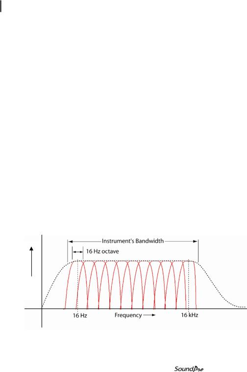
The ability of an instrument to separate a signal into its frequency components is known as a spectral analysis. In sound pressure measurement, the audio spectrum is divided into adjacent frequency bands called octaves, where the center frequency of each octave band is twice the center frequency of the octave band directly below it. There are eleven octave bands in the audio spectrum.
Figure 1-2 illustrates the relationship between the bandwidth of a typical sound measuring instrument and the octave bands that span the audio spectrum. Note that the highest and lowest octaves at 16 Hz and 16 kHz lie entirely within the bandwidth of the instrument.
Level
Figure 1-2: Octave bands
Models SE and DL
3 Frequency resolution
Third -octave bands
Third -octave bands
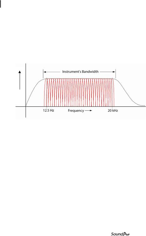
Each octave band can be divided into three adjacent bands called thirdoctave band. Because of the logarithmic relationship between adjacent bands, the center frequencies of third-octave bands differ from each other by 26%. For example, the center frequency of the next third-octave band above the 1000 Hz third-octave band is at 1260 Hz. Figure 1-3 is similar to Figure 1- 2 but shows the thirty-three third-octave bands in relation to the instrument’s bandwidth.
Level
Figure 1-3: Third Octave bands
Naming bands
Bands are conventionally named for their center frequencies in accordance with acoustical industry standards. Table 1-1 identifies the SoundPro SE or DL models that have octave and third-octave bands option with their exact center frequencies and their corresponding standardized names.
Models SE and DL

4 |
Frequency resolution |
|
|
|
|
Naming bands |
|
|
|
|
|
|
||
|
|
|
|
|
|
|
Exact Center |
Names of Octave |
Names of Third-octave |
|
|
Frequency (Hz) |
Bands (Hz) |
Bands (Hz) |
|
|
12.589 |
|
12.5 |
|
|
15.849 |
16 |
16 |
|
|
19.953 |
|
20 |
|
|
25.119 |
|
25 |
|
|
31.623 |
31.5 |
31.5 |
|
|
39.811 |
|
40 |
|
|
50.119 |
|
50 |
|
|
63.096 |
63 |
63 |
|
|
79.433 |
|
80 |
|
|
100.00 |
|
100 |
|
|
125.89 |
125 |
125 |
|
|
158.49 |
|
160 |
|
|
199.53 |
|
200 |
|
|
251.19 |
250 |
250 |
|
|
316.23 |
|
315 |
|
|
398.11 |
|
400 |
|
|
501.19 |
500 |
500 |
|
|
630.96 |
|
630 |
|
|
794.33 |
|
800 |
|
|
1000.0 |
1000 |
1000 |
|
|
1258.9 |
|
1250 |
|
|
1584.9 |
|
1600 |
|
|
1995.3 |
2000 |
2000 |
|
|
2511.9 |
|
2500 |
|
|
3162.3 |
|
3150 |
|
|
3981.1 |
4000 |
4000 |
|
|
5011.9 |
|
5000 |
|
|
6309.6 |
|
6300 |
|
|
7943.3 |
8000 |
8000 |
|
|
10000 |
|
10000 |
|
|
12589 |
|
12500 |
|
|
15849 |
16000 |
16000 |
|
19953 |
|
20000 |
|
Table 1-1: Acoustical range bands
Models SE and DL

5 Logging explained
Analysis type
Analysis type
All SoundPro SE/DL instruments are capable of analyzing sound signals over the full bandwidth of the instrument also referred to as “broadband measurement”. If your instrument comes equipped with a filter, it can perform an octave or a third-octave analysis, or both, depending upon the type of filter installed. You can vary the analysis type between sessions, and the analysis type selection remains constant throughout the session.
Analysis types are identified in SoundPro SE/DL by the following names:
•SLM - Broadband measurements
•1/1 - Octave filtering
•1/3 - Third-octave filtering
•STI-PA -Speech Intelligibility
Logging explained
Although you can view the current sound pressure level at any time that the instrument is operating (See “Bar Chart and Filtered Bar Chart” on page 67), most measurements are reported for data obtained over the entire course of a study or session. In some circumstances, however, you may want to save intermediate measurement results. The SoundPro DL logging option provides you with that capability.
With logging enabled, you can save selected measurements at fixed intervals during a session. You can set logging to occur as often as once per second or as seldom as once per hour. Once the logging characteristics are determined, the setup remains the same for the duration of the session.
Logged data is automatically saved to the instrument’s memory card and can be viewed in QSP II (“Information screen” on page 8).
NOTE: You must use a compatible SD card. For information about replacing the SD card, see “Compatibility” on page 117.
Physical Characteristics
The Display
The transflective LCD display contains an area on the top of the screen for indicators including run, pause, stop icons and a run time clock. The middle of the screen contains a fine resolution of pixels in which data is displayed
Models SE and DL
6 Physical Characteristics
Hardware interfaces
both numerically and graphically. This is explained in further detail in Chapter 2, “The Display and keypad”).
Hardware interfaces
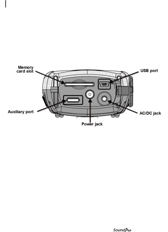
The Hardware Interface Panel, shown in Figure 1- 4, is located under a hinged cover in the base of the instrument. The cover can be lifted by a tab at one side, and snapped shut again by closing and pressing firmly at the center.
Figure 1-4: Hardware Interface Panel
Memory card slot
A Secure Digital (SD) removable memory card is shipped with each SoundPro SE/DL instrument. The card should always be in place when you are operating the instrument. More information about operating with the memory card is given under “Memory card” on page 106.
NOTE: You must use a compatible SD card. For information about replacing the SD card, see “Compatibility” on page 117.
USB port
A USB cable is shipped with each SoundPro SE/DL instrument. One end fits the mini B port in the instrument. The other end fits a standard USB connector on a personal computer. A USB connection to a personal computer allows files to be transferred, settings to be downloaded to the instrument, and postsession analysis to be performed in the computer using data files created in the instrument.
Models SE and DL

7 Physical Characteristics
Hardware interfaces
AC/DC port
Connect a cable with a standard 3.5 mm stereo plug to this jack to obtain AC and DC output signals. Users are responsible for providing their own cable.
Power jack
DC power can be delivered to the instrument through the Power jack. Power will be taken from the external source rather than the instrument’s batteries when the external source provides 8 to 16 volts DC (300ma minimum). Two optional sources for this power are available: a switching power supply connected to an AC source and DC power provided through the accessory jack of most automobiles. For the technical specifications, see “Power sources” in Appendix A. Part numbers are given under “Optional parts” in Appendix A.
Auxiliary port
Use this port to connect the SoundPro SE/DL instrument to other devices. The two types of functions, described below, are available through the terminals of this port. A pinout of the port is provided under “Auxiliary connector” on page 139.
•Digital I/O - A group of contacts within the port provides one, logiclevel input and three, logic-level outputs. See “Digital Outputs/Triggering” on page 50 are information about configuring and using the triggers.
•RS-232 - A group of contacts within the port supports the RS-232 protocol for communication between the instrument and other devices, such as a Global Positioning Satellite (GPS) receiver. See “GPS” on page 54 for information about configuring the port for this purpose.
Models SE and DL
8 Information screen
Screen contents
Information screen
Every SoundPro SE/DL instrument describes its unique characteristics in its Information screen. In the Start screen, press to select Unit Info, then press . The Unit Info screen appears (Figure 1-5).
1 |
|
|
|
|
\UNIT INFO |
|
|
|
|
|
SoundPro DL-1-1/3 |
||
|
|
|
|
|||
2 |
|
|
|
|
Serial # |
BIF120010 |
|
|
|||||
3 |
|
|
|
|
Revision |
B 12M |
|
|
|
|
Installed Features: |
||
|
|
|
||||
|
|
|
|
|
CURVES |
|
|
|
|
|
|
STI-PA |
|
|
|
|
|
|
|
|
Figure 1-5: The Unit Information screen
Screen contents
The lines indicated in Figure 1-7 will contain the following information.
Line 1 - Model number showing, in order, the 3M designation (SE or DL), the Class/Type (1 or 2) and the filter, if installed (1/1, 1/3 or blank).
Line 2 - Unique serial number assigned when the instrument was manufactured.
Line 3 – The installed feature’s field lists any extra options (note: these may be additionally purchased features as displayed above for Curves and STIPA.)
NOTE: It’s a good idea to record Information screen data in the event that you need assistance and the instrument refuses to power up. For 3M assistance, see “Contacting 3M” on page 149.
Models SE and DL
9 Detection Management Software DMS
DMS Start Page
Detection Management Software DMS
3M™ Detection Management Software DMS is used to record, report, chart and analyze data collected for assessment of select occupational health hazards in the workplace. Designed for dosimetry, sound level measurements, heat stress assessments and environmental monitoring, the software helps safety and occupational professionals:
•Retrieve, download, share and save instrument data
•Generate insightful charts and reports
•Export and share recorded data
•Perform “What If” analysis and recalculate data based on selected time intervals
•Set up instruments and check for firmware updates
Some data can only be displayed in DMS. One example is logging data obtained when logging is enabled in an instrument equipped with that option (“Logging” on page 33). Another example is with the GPS function. When enabled the data is viewable in DMS.
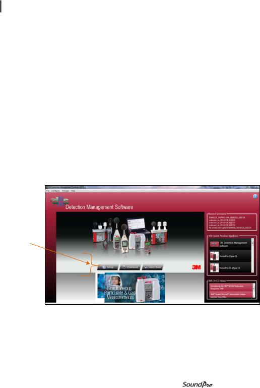
DMS Start Page
Navigational buttons
(1)Setup
(2)Download
(3)Data Finder (look at your session data or use Quick Report feature)
Models SE and DL

10 Detection Management Software DMS
DMS Start Page
This page left intentionally blank
Models SE and DL
|
|
|
CHAPTER |
11 |
|
Checking the equipment |
2 |
|
|
||
|
|
|
|
Getting Started
This chapter provides the basic information you need to “get up and go” essentially right out of the box, including getting your first glimpses of SPL.
Checking the equipment
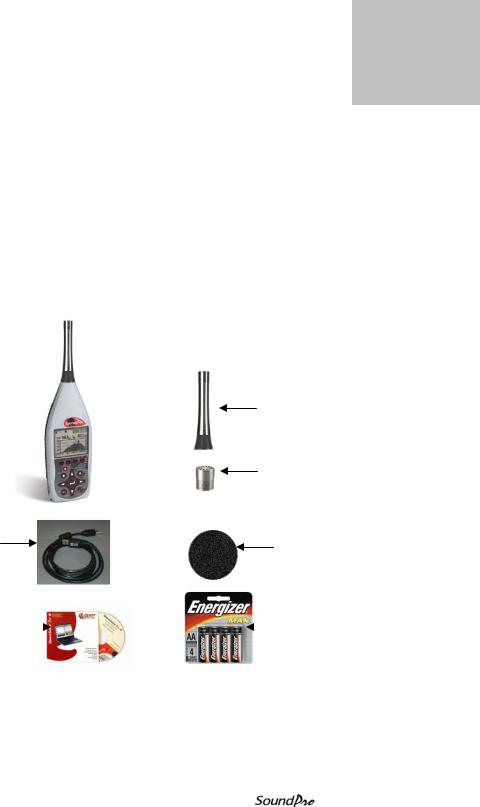
If your instrument was sent to you in a storage case, you will want to remove all the packaging and acquaint yourself with the equipment, so you can quickly get started. The items below are included in a “standard” SoundPro SE or DL kit.
Preamp
SoundPro 
Microphone
• Optional 1”, ½”, and ¼” microphones available
USB cable |
Windscreen |
|
QSPII software |
|
|
|
4-AA alkaline batteries |
• Optional feature |
|
|
|
|
|
|
|
|
|
Figure 2-1: Identify SoundPro equipment
Models SE and DL
12 Microphone and accessories
Installing the preamp
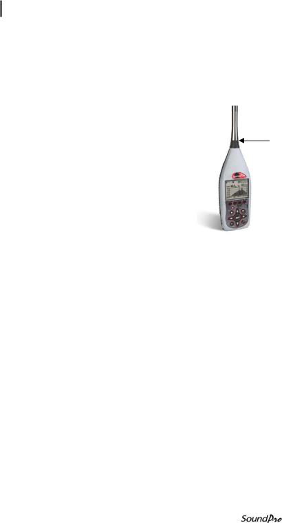
Installing the preamp
The preamplifier is detachable for storage purposes or if you wish to connect an extension cable for distance monitoring.
Connecting to the instrument
Place the preamp connector over the mating connector at the top of the instrument. Gently press down while rotating the preamp until the preamp connector drops slightly in place.
Twist preamp locking ring onto SoundPro
Figure 2-2: SoundPro & Preamp
1.While pressing the connector together to engage the threads, rotate the black knob clockwise to secure the preamp to the instrument. It will fit snuggly.
Connecting an extension cable
Extension cables are available from 3M as options and are typically used to distance the instrument body from the microphone to reduce distorting reflections from the instrument’s case.
1.Attach the cable to the base as if it were the preamp and then follow the steps above “Connecting to the instrument”. Attach the preamp to the other end of the cable.
Microphone and accessories
The instrument is ordered either for Class/Type 1 or Class/Type 2 use. See “Distinctions between models” on page 1 for information about this classification. The microphones are treated differently for the two classes of instruments.
Models SE and DL
13 Microphone and accessories
Class/Type 1 and Class/Type 2 instrument
Class/Type 1 and Class/Type 2 instrument
The SoundPro is shipped with the Type 1 in a protective case with a serial number labeled on the side of the microphone. Similarly, the SoundPro with the Class/Type 2 microphone is also shipped in a protective case. To attach and remove the microphone, please follow one of the types below:
•BK4936 microphone - Remove the microphone from its case and thread it on the SoundPro SE/DL preamp in accordance with the instructions provided in the microphone case. Note that the BK4936 microphone is provided with a Random Incidence Corrector (RIC). Use the same microphone instructions for information about using and installing that device.
•All other Class/Type 1 microphones - Remove the microphone from its protective case and thread it on the preamp. Before using, be sure to remove the plastic cap and save it in the case for future use.
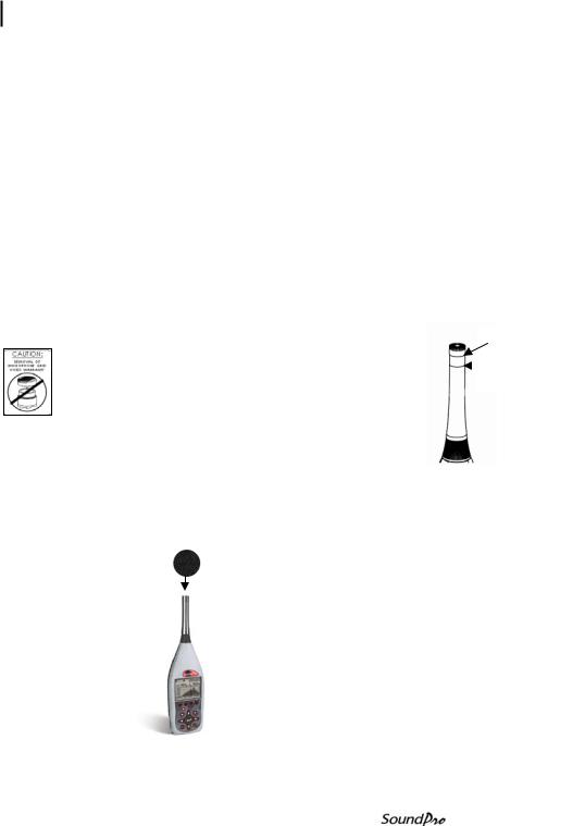
•Class/Type 2 microphones – Remove the
microphone from its protective case and thread it on |
|
No |
the preamp. Before using, be sure to remove plastic |
|
Yes |
cap and save it in the case for future use. |
|
|
|
NOTE: to properly remove the microphone, please adhere to the caution sticker located on the backside of the instrument and the drawing to the right.
Windscreen
Use a windscreen that fits the tip of the microphone to reduce sound disturbances caused by physical contact and wind turbulence. 3M provides the WS-7 windscreen that fits a ½-inch microphone with every instrument kit. If you didn’t order a ½-inch microphone, or if you have one of different size, you may wish to order a windscreen for the other size.
Figure 2-3: SoundPro with microphone and windscreen
Models SE and DL
14 Providing power
Installing Batteries
Providing power
You can power the instrument with internal batteries or from an external power source. There are two optional sources which include a universal power supply 9V/.66A 2.1 mm and an auto DC jack cable 12V. (See Optional Parts, in Appendix A for more details.)
Installing Batteries
The instrument requires four AA-sized batteries. Disposable alkaline batteries are satisfactory, but you may also use rechargeable Nickel Metal Hydride (NiMH) batteries.
•Rechargeable batteries ~ The instrument does not contain a recharging circuit. Recharge batteries externally using the recharging device available from 3M or a compatible device available elsewhere.
•Selecting batteries ~ Do not mix battery types or batteries with significantly different charge levels.
NOTE: To avoid possible battery leakage, remove the batteries when the meter is not in use for prolonged periods.
To install batteries
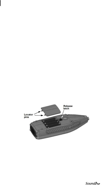
1.With the back of the instrument facing up, push the release latch to pop open the battery lid (Figure 2-1).
Figure 2-4: Installing batteries
2.Lift off the lid and set aside. Wedge out the four batteries.
3.Replace the batteries with fresh batteries, taking care that you orient all batteries with the positive ends toward the base, as shown in the drawing.
4.Re-insert the lid by fitting its locator pins into slots in the base end of the battery compartment. The lid should fit snugly when correctly inserted.
Models SE and DL
15 Providing power
Battery power explained
5.Press the top edge of the lid to snap it into the latch.
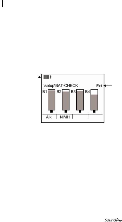
6.Verify or set the type in the Battery Check screen. (See the next section “Checking battery power”.)
Battery power explained
The battery check screen is used to determine the battery/power status of the instrument. When operating on batteries, the grey area in each cell graphic indicates the charge on each cell (Figure 2-5).
When operating on an external power source (see next section, “external power sources”), the external power will take precedence over batteries if installed.
Battery indicator
If all bars appear up to starting line, this indicates full battery power
Externally powered
If using an external power source, EXT will appear and all batteries will be fully shaded indicating full power capacity.
Figure 2-5: Battery check screen
Checking or changing type
The battery type selection in this display affects the accuracy of the Battery Indicator that appears in many SoundPro SE/DL displays.
NOTE: It is recommended to match the battery type to the type of batteries installed in the instrument, or you may experience an unexpected shutdown.
Models SE and DL
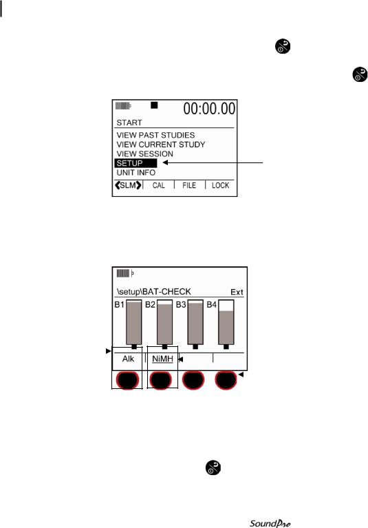
16 Providing power
Checking or changing type
|
Battery Check screen |
|
1. |
Turn on the SoundPro SE/DL by pressing On/Off/ESC |
. You will be at |
the start screen.
• If turned on, ensure you are at the start screen by pressing On/Off/Esc repeatedly until the start screen appears.
Setup
Figure 2-6: Selecting Setup in the Start Screen
2.Press Up/Down arrows to highlight Setup and then press Enter
  .
.
3.In the Setup screen, select Battery, then press Enter  . The Battery Check screen appears.
A: Press softkey |
|
|
|
|
B : Press softkey |
|
|
|
|
|
|
||||
to select Alkaline |
|
|
|
to select NiMH |
|
||
|
|
|
|
||||
|
|
|
|
|
|
Softkey buttons |
|
|
|
|
|
|
|
|
|
|
|
|
|
|
|
|
|
|
|
|
|
|
|
||
|
|
|
|
|
|
|
|
Figure 2-7: Selecting battery type in battery check screen
4.Press the softkey that corresponds with the installed battery type (See “A” or “B” in Figure 2-7 for selection). The label above the softkey is underlined to indicate the current selection.
5. When completed, press On/Off/Esc |
once to return to the Setup screen |
and twice to return to the start screen. |
|
|
Models SE and DL |
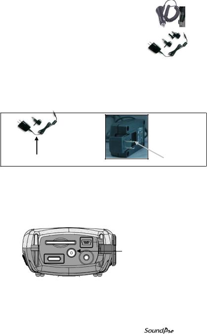
17 |
Providing power |
|
Using power supply or auto adapter |
|
Using power supply or auto adapter
If you obtained the optional Universal power supply |
|
|
|
9V cable or the Auto DC Jack 12 VDC adapter from |
|
|
Auto |
3M, plug them into their respective power sources |
|
|
adapter |
and the other end into the Power jack of the |
|
|
|
|
|
|
|
instrument. If the external power source provides |
|
|
|
|
|
|
|
the correct voltage (8-16 VDC) and sufficient |
|
|
Universal |
|
|||
current (300 mA minimum), it will be used in |
|
|
power |
place of the batteries if they’re installed in the |
|
|
supply |
instrument. |
|
|
|
Figure 2-8 illustrates the assembly of the Universal power supply and the plug adapter. It slides into place by guiding it down the back cavity (opening) of the power supply.
- NOTE: the example is a typical adapter which may be different than the one you are using. Mechanically, it will function similarly.
A. Universal power supply 9V |
B. Slide plug adapter into the crevices of base |
|
Figure 2-8: Attaching the charger adapter with the plug adapter
Connecting power supply source
1.Ensure the power supply is assembled (for universal power supply only).
2.Plug the power cord into the power jack by opening the base cover. Attach the opposite end into the power supply (i.e., outlet/automobile jack) (as discussed in “Hardware interfaces”, page 6.)
Power Jack
Figure 2-9: Base (or bottom) of SoundPro
3. Plug the opposite end into the power supply.
Models SE and DL
Loading...