


3M-Matic™
Instructions and Parts List
800af-s Type 10500
Stainless Steel
Adjustable
Case Sealer
with
AccuGlide™ SST
Taping Heads
Serial No.
For reference, record machine serial number here.
3M Industrial Adhesives and Tapes
3M Center, Building 220-5E-06
St. Paul, MN 55144-1000
Important Safety
Information
BEFORE INSTALLING OR OPERATING THIS EQUIPMENT
Read, understand, and follow all safety and operating instructions.
Spare Parts
It is recommended you immediately order the spare parts listed in the "Spare Parts/Service Information" section. These parts are expected to wear through normal use, and should be kept on hand to minimize production delays.
3M-Matic, AccuGlide, and Scotch are Trademarks of 3M, St. Paul, MN 55144-1000
PrintedinU.S.A.
©3M 2005 44-0009-2040-3 (A)

Replacement Parts and Service Information
To Our Customers:
This is the 3M-Matic™/AccuGlide™/Scotch® equipment you ordered. It has been set up and tested in the factory with Scotch® tapes. If technical assistance or replacement parts are needed, call or fax the appropriate number listed below.
Included with each machine is an Instructions and Parts List manual.
Technical Assistance:
3M-Matic™ Helpline – 1-800/328 1390. Please provide the customer support coordinatorwiththemachinenumber,machinetype/modelandserialnumber. If youhaveatechnicalquestionthatdoesnotrequireanimmediateresponse,you mayFaxit to 651-736-7282.
Replacement Parts and Additional Manuals
Order parts by part number, part description and quantity required. Also, when orderingpartsand/oradditionalmanuals,includemachinename,numberand type. A parts order form is provided at the back of this manual.
3M/Tape Dispenser Parts |
|
241 Venture Drive |
1-800/3449883 |
Amery,WI 54001-1325 |
FAX#715/2688153 |
Minimum billing on parts orders will be $25.00. Replacement part prices available on request. $10.00 restocking charge per invoice on returned parts.
Note: Outside the U.S., contact the local 3M subsidiary for parts ordering information.
3M Industrial Adhesives and Tapes
3M Center, Building 220-5E-06
St. Paul, MN 55144-1000
3M-Matic™,AccuGlide™ andScotch™ areTrademarksof3M, St. Paul, MN 55144-1000
PrintedinU.S.A.
©3M2005 44-0009-1851-4(F)

Replacement Parts And Service Information
To Our Customers:
This is the 3M-Matic™/AccuGlide™/Scotch® equipment you ordered. It has been set up and tested in the factory with Scotch® tapes. If any problems occur when operating this equipment and you desire a service call or phone consultation, call, write or fax the appropriate number listed below.
Included with each machine is an Instructions and Parts List manual.
SERVICE,REPLACEMENTPARTSANDADDITIONALMANUALS
AVAILABLE DIRECT FROM:
Order parts by part number, part description and quantity required. Also, when orderingpartsand/oradditionalmanuals,includemachinename,numberandtype.
3M Industrial Adhesives and Tapes
3M Center, Building 220-5E-06
St. Paul, MN 55144-1000
3M-Matic™,AccuGlide™ andScotch™ areTrademarksof3M, St. Paul, MN 55144-1000
PrintedinU.S.A.
©3M2005 44-0009-1852-2(E)

Instruction Manual
800af-s Stainless Steel Adjustable Case Sealer
Type 10500
This instruction manual is divided into two sections as follows:
Section I Includes all information related to installation, operation and parts for the case sealer. Section II Includes specific information regarding the AccuGlide™ SST 2 Inch Taping Heads.
Table of Contents |
Page |
Intended Use ................................................................................................................................... |
1 |
Equipment Warranty and Limited Remedy ..................................................................................... |
2 |
Contents – 800af-s Stainless Steel Adjustable Case Sealer ......................................................... |
2 |
Important Safeguards ..................................................................................................................... |
3 - 6 |
Specifications .................................................................................................................................. |
7 - 11 |
Set-Up Procedure ........................................................................................................................... |
12 - 15 |
ReceivingandHandling ....................................................................................... |
12 |
Machine Set-Up .................................................................................................. |
12 - 15 |
Initial Start-Up of Case Sealer ............................................................................. |
15 |
Operation ......................................................................................................................................... |
16 - 25 |
Case Sealer Components ................................................................................... |
16 - 18 |
Operation "Warnings" ......................................................................................... |
19 |
TapeLoading/Threading ...................................................................................... |
19 |
Box Size Set-Up ................................................................................................. |
20 - 24 |
Box Sealing ........................................................................................................ |
24 |
Box Jams ............................................................................................................ |
25 |
Maintenance .................................................................................................................................... |
26 - 29 |
Cleaning .............................................................................................................. |
26 |
Lubrication .......................................................................................................... |
26 |
Drive Belt Replacement/Tension Adjustment ...................................................... |
27 - 28 |
Air Line Filter ...................................................................................................... |
29 |
Circuit Breaker .................................................................................................... |
29 |
Knife Replacement, Taping Heads ...................................................................... |
29 |
Adjustments .................................................................................................................................... |
30 - 32 |
Gate Operation ................................................................................................... |
30 |
Drive Belt Tension ............................................................................................... |
30 |
Taping Head Adjustments ................................................................................... |
30 |
UpperTapingHeadLeveling ................................................................................ |
31 |
Gate Pressure Regulator ..................................................................................... |
32 |
Gate Stroke Setting ............................................................................................ |
32 |
(Table of Contents continued on next page) |
|
i

Table of Contents (Continued) |
|
Page |
Special Set-Up Procedure ................................................................................................................ |
|
34 - 37 |
Changing Drive Belt Height ................................................................................. |
|
34 |
Changing the Tape Leg Length............................................................................ |
|
35 |
Outer Column Re-Positioning .............................................................................. |
|
36 - 37 |
Troubleshooting ............................................................................................................................... |
|
38 - 39 |
TroubleshootingGuide ........................................................................................ |
|
38 - 39 |
Pneumatic Diagram ......................................................................................................................... |
|
40 |
Electrical Diagram ........................................................................................................................... |
|
41 - 42 |
Spare and Miscellaneous Parts ....................................................................................................... |
|
44 |
Spare Parts ........................................................................................................ |
|
44 |
Label Kit ............................................................................................................. |
|
44 |
Tool and Parts Kit ............................................................................................... |
|
44 |
Replacement Parts Ordering Information and Service.......................................... |
|
44 |
Options/Accessories ....................................................................................................................... |
|
45 |
Replacement Parts Illustrations and Parts Lists ..................................................... |
(Yellow Section) |
46 - 90 |
Section I – AccuGlide™ SST 2 Inch Taping Heads
(See Section II for Table of Contents)
i
Intended Use
The intended use of the 3M-Matic™ 800af-s Stainless Steel Adjustable Case Sealer with AccuGlide™ SST Taping Heads is to automatically seal the top and bottom center seams of regular slotted containers without the need for an operator. It will accept filled regular slotted containers from an existing conveyor, fold the top flaps and apply a "C" clip of Scotch® pressure-sensitive film box sealing tape to the top and bottom center seams of the box. An integral gate provides the proper spacing of incoming boxes. Infeed conveyor speed must not exceed 0.3 m/s [60 F.P.M.] maximum. The machine has been designed and tested for use with Scotch® pressure-sensitive film box sealing tape.
3M-Matic™ 800af-s Stainless Steel Adjustable Case Sealer, Type 10500
1

Equipment Warranty and Limited Remedy: THE FOLLOWING WARRANTY IS MADE IN LIEU OF ALL OTHER WARRANTIES, EXPRESS OR IMPLIED, INCLUDING, BUT NOT LIMITED TO, THE IMPLIED WARRANTY OF MERCHANTABILITY, THE IMPLIED WARRANTY OF FITNESS FOR A PARTICULAR PURPOSE AND ANY IMPLIED WARRANTY ARISING OUT OF A COURSE OF DEALING, A CUSTOM OR USAGE OF TRADE:
3M sells its 3M-Matic™ 800af-s Type 10500 with the following warranties:
1.The drive belts and the taping head knives, springs and rollers will be free from all defects for ninety (90) days after delivery.
2.All other taping head parts will be free from all defects for three (3) years after delivery.
3.All other parts will be free from all defects for two (2) years after delivery.
If any part is proved to be defective within its warranty period, then the exclusive remedy and 3M’s and seller’s sole obligation shall be, at 3M’s option, to repair or replace the part, provided the defective part is returned immediately to 3M’s factory or an authorized service station designated by 3M. A part will be presumed to have become defective after its warranty period unless the part is received or 3M is notified of the problem no later than five (5) calendar days after the warranty period. If 3M is unable to repair or replace the part within a reasonable time, then 3M at its option, will replace the equipment or refund the purchase price. 3M shall have no obligation to provide or pay for the labor required to install the repaired or replacement part. 3M shall have no obligation to repair or replace (1) those parts failing due to operator misuse, carelessness, or due to any accidental cause other than equipment failure, or (2) parts failing due to non-lubrication, inadequate cleaning, improper operating environment, improper utilities or operator error.
Limitation of Liability: 3M and seller shall not be liable for direct, indirect, special, incidental or consequential damages based upon breach of warranty, breach of contract, negligence, strict liability or any other legal theory.
The foregoing Equipment Warranty and Limited Remedy and Limitation of Liability may be changed only by a written agreement signed by authorized officers of 3M and seller.
Contents – 800af-s Stainless Steel Adjustable Case Sealer
(1)800af-s Stainless Steel Adjustable Case Sealer, Type 10500
(1)Tool/Spare Parts Kit
(1)Instruction and Parts Manual
ScotchT® , AccuGlideTM, and 3M-MaticTM are Trademarks of 3M, St. Paul, Minnesota 55144-1000
2
Important Safeguards
This safety alert symbol identifies important messages in this manual.
READ AND UNDERSTAND THEM BEFORE INSTALLING OR OPERATING THIS EQUIPMENT.
Explanation of Signal Word Consequences
WARNING: Indicates a potentially hazardous situation, which, if not avoided, could result in death or serious injury and/or property damage.
CAUTION: Indicates a potentially hazardous situation, which, if not avoided, may result in minor or moderate injury and/or property damage.
 WARNING
•To reduce the risk associated with mechanical and electrical hazards:
−Read, understand and follow all safety and operating instructions before operating or servicing the case sealer
−Allow only properly trained and qualified personnel to operate and/or service this equipment
−Turn electrical and air supply off and disconnect before performing any adjustments, maintenance or servicing the machine or taping heads
•To reduce the risk associated with pinch, entanglement and impact hazards:
−Do not leave the machine running while unattended
−Turn the machine off while not in use
−Never attempt to work on any part of the machine, load tape, or remove jammed boxes from the machine while the machine is running
−Keep away from moving belts and pneumatically controlled kicker
•To reduce the risk associated with hazadous voltage:
−Position electrical cord away from foot and/or vehicletraffic
3
 WARNING(continued)
•To reduce the risk associated with impact hazards:
−Always use appropriate supporting means when working under the upper drive assembly
−Turn air supply off and be sure flap kicker is downbeforeservicing
−Never operate this equipment with safety interlocks or guarding removed
•To reduce the risk associated with sharp blade hazards:
−Keep hands and fingers away from tape cutoff blades under orange blade guards. The blades are extremely sharp
•To reduce the risk associated with fire and explosion hazards:
−Do not operate this equipment in potentially flammable/explosiveenvironments
•To reduce the risk associated with muscle strain:
−Use the appropriate rigging and material handling equipment when lifting or repositioning this equipment
−Use proper body mechanics when removing or installing taping heads that are moderately heavy or may be considered awkward to lift
−Use proper body mechanics when removing or clearing jammed boxes from the machine
 CAUTION
•To reduce the risk associated with pinch and entanglement hazards:
−Keep hands clear of the upper head support assembly as boxes are transported through the machine
−Always feed boxes into the machine by pushing only from the end of the box
−Keep hands, hair, loose clothing, and jewelry away from moving belts and taping heads
•To reduce the risk associated with pinch hazards:
−Keep away from the pneumatically controlled upper drive assembly and box centering guides when air and electric supplies are on
Important Safeguards (Continued)
This safety alert symbol identifies important messages in this manual.
READANDUNDERSTANDTHEMBEFORE INSTALLING OR OPERATING THIS EQUIPMENT.
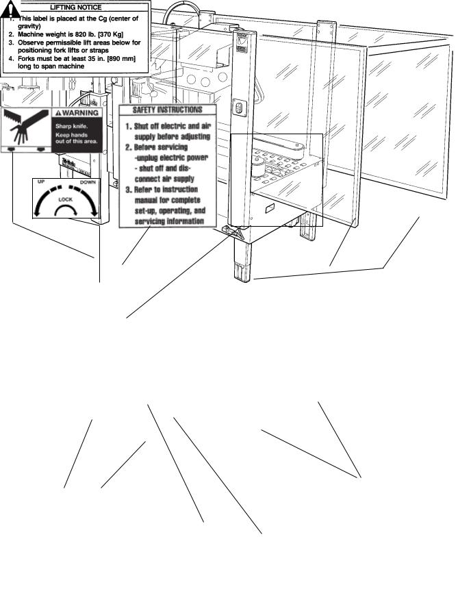
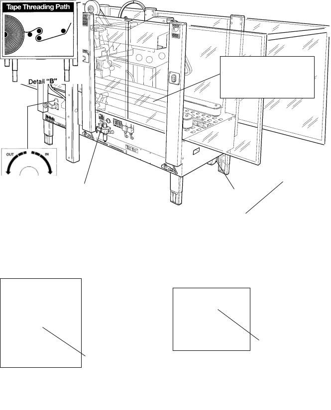
Important – In the event the following safety labels are damaged or destroyed, they must be replaced to ensure operator safety. Replacement part numbers for individual labels are shown in Figures 1-1, or a label kit, part number 78-8133-9619-5, is available that includes all labels used on the machine.
Figure 1-1 – Replacement Labels/3M Part Numbers
4
5

Important Safeguards (Continued)
 WARNING
• To reduce the risk associated with mechanical and electrical hazards:
−Allow only properly trained and qualified personnel to operate and/or service this equipment
Operator Skill Level Descriptions
Skill 1 - Machine Operator
This operator is trained to use the machine with the machine controls, to feed cases into the machine, make adjustments for different case sizes, to change the tape and to start, stop and restart production.
Important – the factory manager must ensure that the operator has been properly trained on all the machine functions before starting work.
Skill 2 - Mechanical Maintenance Technician
This operator is trained to use the machine as the MACHINE OPERATOR and in addition is trained to work with the safety protection disconnected, to check and adjust mechanical parts, to carry out maintenance operations and repair the machine. He is not qualified to work on live electrical components.
Skill 2a - Electrical Maintenance Technician
This operator is trained to use the machine as the MACHINE OPERATOR and in addition is trained to work with the safety protection disconnected, to make adjustments, to carry out maintenance operations and repair the electrical components of the machine. He is qualified to work on live electrical panels, connector blocks, control equipment, etc.
Skill 3 - Specialist From the Manufacturer
Skilled operator sent by the manufacturer or its agent to perform complex repairs or modifications, when agreed with the customer.
Operator's Skill Levels Required to Perform the Main Operations on Machine
Operation |
|
State of the Machine |
Operator's |
Number of |
|
|
Skill |
Operators |
|||
|
|
|
|
||
|
|
|
|
|
|
Installation and set up of the machine. |
|
Running with safety protections |
2 and 2a |
2 |
|
|
disabled. |
||||
|
|
|
|
||
|
|
|
|
|
|
Adjustment of the box size. |
|
Stopped by pressing the |
1 |
1 |
|
|
EMERGENCY |
STOP button. |
|||
|
|
|
|
||
|
|
|
|
|
|
Tape replacement. |
|
Stopped by pressing the |
1 |
1 |
|
|
EMERGENCY |
STOP button. |
|||
|
|
|
|
||
|
|
|
|
|
|
Replacement of blades. |
|
Electric power disconnected. |
2 |
1 |
|
|
|
|
|
|
|
Replacement of drive belts. |
|
Electric power disconnected. |
2 |
1 |
|
|
|
|
|
|
|
Ordinary maintenance. |
|
Electric power disconnected. |
2 |
1 |
|
|
|
|
|
|
|
Extraordinary maintenance |
|
Running with safety protections |
3 |
1 |
|
(mechanical). |
|
disabled. |
|||
|
|
|
|||
|
|
|
|
|
|
Extraordinary maintenance (electrical). |
|
Running with safety protections |
2a |
1 |
|
|
disabled. |
||||
|
|
|
|
||
|
|
|
|
|
|
6

Specifications
1.Power Requirements:
Electrical – 115 VAC, 60 Hz, 3.8 Amp (440 watts)
Pneumatic – 6.5 bar gauge pressure [95 PSIG], 2.5 SCFM
75 liter/minute @ 21° C., 1.01 bar maximum at maximum cycle rate. A pressure regulator/filter is included.
The machine is equipped with two 1/6 HP gearmotors and comes with an 2.4 m [8 foot] standard neoprene covered power cord and a grounded plug. Contact your 3M Representative for power requirements not listed above.
2.Operating Rate:
Note - Machine is shipped with both cams (A and B) installed. To obtain production rate shown with dotted line (cam A only), cam B must be removed. See "Adjustments – Gate Operation".
(continued)
7

Specifications (Continued)
3.Operating Conditions:
Use in a relatively clean environments at 5o to 40o C [40o to 105o F] with clean, dry boxes.
Important – Machine should not be washed down .
 WARNING
• To reduce the risk associated with fire and explosion hazards:
−Do not operate this equipment in potentially flammable/explosiveenvironments
4.Tape:
Scotch® pressure-sensitive film box sealing tapes.
5.Tape Width:
36 mm [1-1/2 inch] minimum to 48 mm [2 inch] maximum
6.Tape Roll Diameter:
Up to 405 mm [16 inch] maximum on a 76.2 mm [3 inch] diameter core. (Accommodates all system roll lengths of Scotch® film tapes.)
7.Tape Application Leg Length – Standard:
70 mm ±6 mm [2-3/4 inch ±1/4 inch]
8.Box Board:
Style – regular slotted containers – RSC
125 to 275 P.S.I. bursting test, single wall B or C flute.
(continued)
8
Specifications (Continued)
9.Box Weight and Size Capacities:
A.Box Weight, filled – contents must support flaps.
Minimum – weight must be sufficient to hold carton on the conveyor bed with bottom flaps fully closed or 1.4 kg [3 lb.] minimum.
Maximum – 40 kg [85 lb.]
B.Box Size:
Minimum: |
Length – 150 mm [6 inches] |
Maximum: |
Length – 760 mm [30 inches] |
|
Width – 120 mm [4-3/4 inches] |
|
Width – 545 mm [21-1/2 inches] |
|
Height – 120 mm [4-3/4 inches]* |
|
Height – 620 mm [24-1/2 inches]** |
*Boxes lower than 165 mm [6-1/2 inches] and wider than 320 mm [12-1/2 inches] require removal of compression rollers.
**With columns adjusted to upper position, maximum box height increase to 725 mm [28-1/2 inches] and minimum box height increases to 225 mm [8-3/4 inches]. See "Special Set-Up Procedure – Outer Column Re-Positioning".
Note – The case sealer is designed to accommodate most boxes complying with the 1976 FBA and PMMI*** voluntary standard "Tolerances for Top Opening" regular slotted containers (RSC).
Two of the requirements of the standard are the following:
1.The box length is not more than twice the box width.
2.The box length is not more than four times the box depth.
In addition, the box score lines must be sufficient to facilitate automatic flap folding. Certain environmental conditions, such as high humidity, can be detrimental to automatic flap folding.
***Fibre Box Association, Packaging Machinery Manufacturer's Association
DETERMINE THE BOX LIMITATIONS BY COMPLETING THIS FORMULA:
BOX LENGTH IN DIRECTION OF SEAL |
MUST BE GREATER THAN .6 |
BOX HEIGHT |
|
If any of the above criteria are not met boxes should be test run to assure proper machine performance.
(continued)
9

Specifications (Continued)
Dimensions are listed on the following page.
10
10. Machine Dimensions: |
|
|
|
|
|
|
|
|
W |
L1 |
L2 |
|
H |
B |
F |
Minimum |
985 |
1920 |
3445 |
1575 |
- 2185 |
610 - 890 |
825 |
mm |
|||||||
[inches] |
[38.75] |
[75.63] |
[135.63] |
[62 - 86] |
[24 - 35] |
[32.5] |
|
Maximum |
985 |
1920 |
3445 |
1575 |
- 2185 |
610 - 890 |
825 |
mm |
|||||||
[inches] |
[38.75] |
[75.63] |
[135.63] |
[62 |
- 86] |
[24 - 35] |
[32.5] |
|
L3 |
L4 |
C |
Minimum |
725 |
800 |
135(optional) |
mm |
|||
[inches] |
[28.5 |
[31.5] |
[5.25] |
Maximum |
725 |
800 |
135(optional) |
mm |
|||
[inches] |
[28.5] |
[31.5] |
[5.25] |
Weight – 410 kg [900 lbs.] crated (approximate) 370 kg [820 lbs.] uncrated (approximate)
11.Set-Up Recommendations:
•Machine must be level.
•Customer supplied infeed and exit conveyors (if used) should provide straight and level box entry and exit.
•Exit conveyors (powered or gravity) must convey sealed boxes away from machine.
11

Installation and Set-Up
Receiving And Handling
After the machine has been uncrated, examine the case sealer for damage that might have occurred during transit. If damage is evident, file a damage claim immediately with the transportation company and also notify your 3M Representative.
Machine Set-Up
It is recommended that the case sealer be set-up and operated with product before placing it in the production line. This approach will allow your thorough review and familiarization with the 800af-s before subjecting it and operating personnel to a production situation where time for set-up, adjustments, and operator training usually becomes limited.
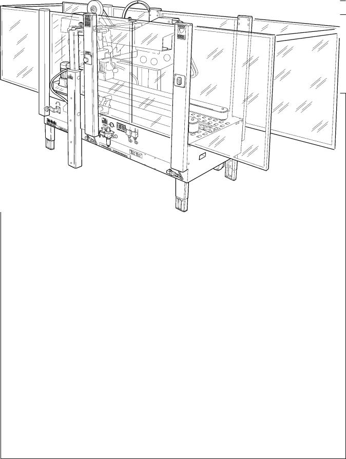
The following instructions are presented in the order recommended for setting up and installing the case sealer. Following them step by step will result in an installation in your production line that best utilizes the many features built into the case sealer. Refer to Figure 3-1 and 3-2 to identify the various components and controls of the machine.
For future reference, record machine serial number on front cover of this instruction manual in the space provided.
IMPORTANT – Read "Warnings" before attempting to set up the case sealer for operation.
1.Follow "Unpacking Instructions" label attached to corrugated packing cover.
2.Use appropriate material handling equipment to remove the machine from the pallet and move it into position.
Whenever the machine is lifted with a fork truck, insure that the forks span completely across the machine frame and do not contact any wiring or mechanism under the machine frame. In some cases the lower taping head may need to be removed to avoid damage.
 WARNING
•To reduce the risk associated with muscle strain:
−Use the appropriate rigging and material handling equipment when lifting or repositioning this equipment
2.Remove and discard cable ties on upper head assembly.
3.Install the crank handle on the top of the left column, as shown in Figure 2-1A.
4.Install upper tape drum bracket on the top cross bar, as shown in Figure 2-1B.
5.Install the two infeed end guards. Attach the guards to the infeed end vertical masts, as shown in Figure2-1C.
6.Raise upper head assembly (turn crank handle counterclockwise). Install the machine stops (from parts bag). Mount these stops as shown in Figure 2-1D using lowest hole position on brackets.
7.The lower tape drum bracket assembly is mounted on the lower head in the standard position. Ensure that the bracket assembly is mounted straight down, as shown in Figure 2-2A. The tape drum bracket assembly can be pivoted to provide clearance or for retrofit in certain cases.
Lower outboard tape roll mounting (alternate position) –
a.Remove lower taping head from machine.
b.Remove existing tape drum bracket from taping head and replace with bracket/roller assembly (shipped loose), Figure 2-2B. Replace taping head in machine.
c.Install tape drum bracket (removed from taping head) on exit end of machine lower frame as shown in Figure 2-2B.
12
Installation and Set-Up (Continued)
Figure 2-1 – Installation and Set-Up
Figure 2-2 – Lower Tape Drum Bracket Position
13
Installation and Set-Up (Continued)
8.Install case sealer in production line. When installing the case sealer, be sure to observe the following guidelines.
a.Case sealer must be installed level – it is not designed to convey boxes uphill.
b.Infeed conveyor must convey boxes to case sealer at a speed not to exceed 0.30 m/s [60 f/m].
c.Precautions must be taken to prevent excessive box pressure against the case sealer infeed gate. This will help to prevent damage to the boxes and ensure proper performance.
d.Infeed and exit conveyors must provide straight entrance and exit of boxes to/from case sealer and exit conveyor must positively convey boxes away from machine.
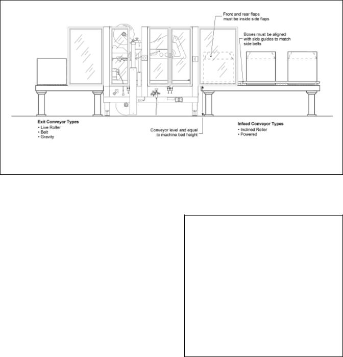
e.Refer to Figure 2-3 for suggested conveyor types that can be used with the case sealer.
Figure 2-3 – Conveyor Systems
9.Adjust case sealer bed height. The adjustable legs provide different machine bed heights from 610 mm [24 inches] minimum to 890 mm
[35 inches] maximum.
Refer to Figure 2-4 and set the machine bed height as follows:
a.Block up the machine frame to allow adequate leg adjustment.
b.Loosen, but do not remove, two M8 x 1.25 mm socket head screws in one leg (use M6 hex key wrench). Adjust the leg length for the desired machine bed height. Retighten the two screws to secure the leg. Adjust all four legs equally.
10.Tape width – the taping heads have been preset to accommodate 72 mm [3 inch] wide tape
rolls. To apply narrower width tapes, refer to |
Figure 2-4 – Conveyor Bed Height Adjustment |
Section II, "Adjustments – Tape Web |
|
Alignment". |
|
14

Installation and Set-Up (Continued)
11.Box size capacity (height) – at its factory setting, the case sealer handles box sizes up to 620 mm [24-1/2 inches] maximum height. If larger capacity is needed, the machine can be adjusted to accommodate up to 725 mm [28-1/2 inches] high boxes. Refer to "Special Set-Up Procedure – Outer Column
Re-Positioning", for set-up information.
12.Drive Belt Height – drive belt assemblies can be raised 50 mm [2 inches] to provide better conveying of tall boxes. Refer to "Special SetUp Procedure – Changing Drive Belt Height".
13.Pneumatic connection.
depressed and that all packaging materials and tools are removed from the machine. Do not plug electrical cord into outlet until ready to run machine.
Note – Machines outside the U.S. may be equipped with 220/240 Volt, 50 Hz systems, or other electrical requirements compatible with local practice.
 WARNING
•To reduce the risk associated with mechanical and electrical hazards:
−Turn electrical and air supply off and disconnect before performing any adjustments, maintenance or servicing the machine or taping heads
The case sealer requires a 6.5 bar gauge pressure [95 PSIG] 75 liter/min @21°C, 1.01 bar [2.5 SCFM] compressed air supply. As shown in Figure 2-5 an on/off valve, pressure regulator, and filter are provided to service the air supply.
The main air supply line should be connected to the on/off valve by means of the barbed fitting and hose clamp provided on the outer side of the on/off valve as shown in Figure 2-5. The customer supplied air hose (5/16 inch [8 mm] ID) should be slipped over the barbed fitting and clamped tightly in place.
If another type of connector is desired, the fitting can be removed and replaced with the desired 1/4-18 NPT threaded connector.
Always turn the valve "Off" when air supply line is being connected or disconnected.
14.Electrical connection and controls – the electrical control box shown in Figure 3-1, contains the "On/Off" switch with pre-set breaker and can be located on either side of the machine frame for operator convenience. A standard three conductor power cord with plug is provided at the back of the electrical control box for 115 Volt, 60 Hz, 3.8 Amp electrical service. The receptacle providing this service shall be properly grounded. Before the power cord is plugged into 115 Volt, 60 Hz outlet, make sure red "Off" button is
Initial Start-Up of Case Sealer
After completing the "Set-Up" procedure, continue through ""Operation", to be sure case sealer is properly adjusted to run product.
Figure 2-5 – Pneumatic Connection
15
Operation
 WARNING
•To reduce the risk associated with mechanical and electrical hazards:
ŠRead, understand and follow all safety and operating instructions before operating or servicing the case sealer
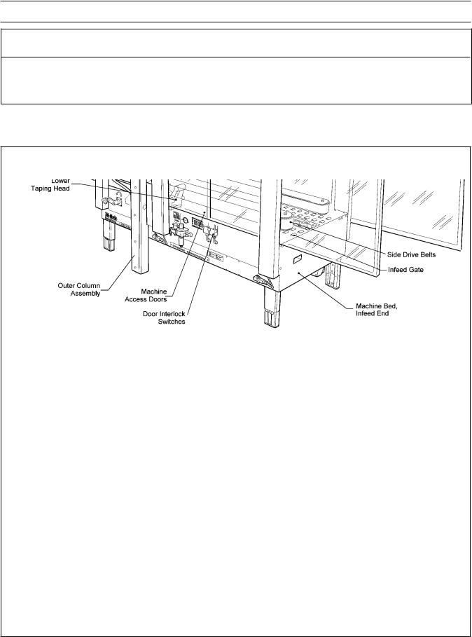
Refer to Figure 3-1 and 3-2 to acquaint yourself with the various components and controls of the 800af case sealer. Also see Figures 3-1 and 3-2 in Section II for taping head components.
Figure 3-1 – Case Sealer Components
16
Operation (Continued)
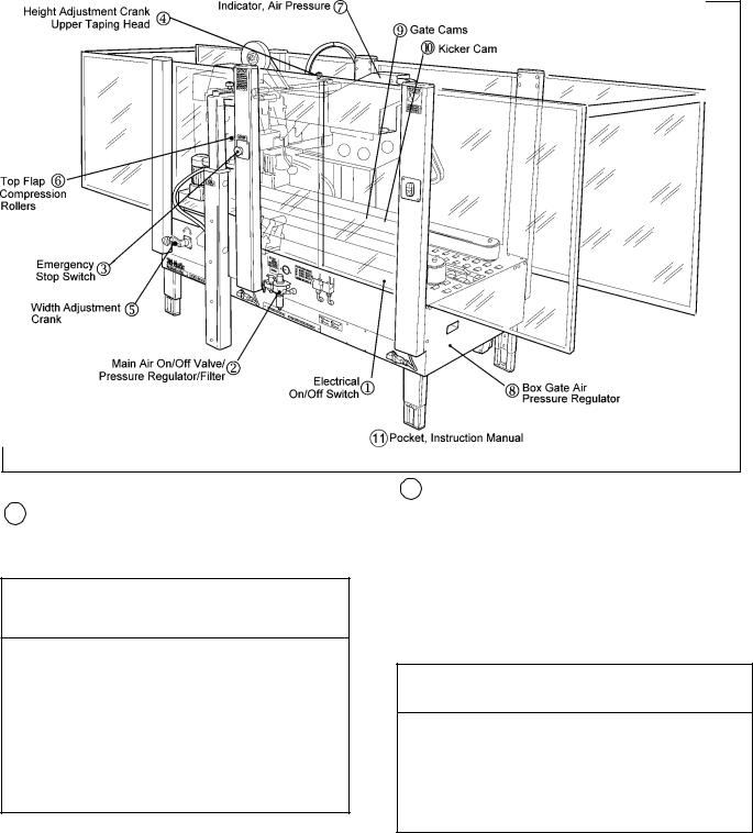
Figure 3-2 – Controls, Valves and Switches
1Electrical "On/Off" Switch
The box drive belts are turned on and off (off button is red) with the electrical switch on the side of the machine guard at the infeed end.
 WARNING
•To reduce the risk associated with mechanical and electrical hazards:
−Allow only properly trained and qualified personnel to operate and/or service this equipment
−Turn electrical and air supply off and disconnect before performing any adjustments, maintenance or servicing the machine or taping heads
Note – The case sealer has a circuit breaker located in the electrical enclosure on the lower right side of the machine frame. If circuit becomes overloaded and circuit breaker trips, unplug the machine electrical cord and determine cause of overload. After two minutes, remove the electrical control box cover and reset the circuit breaker by pressing the "Reset" button and then the "Start" button on the circuit breaker. Replace the control box cover, plug machine electrical cord into outlet and restart machine by pressing green "On" button.
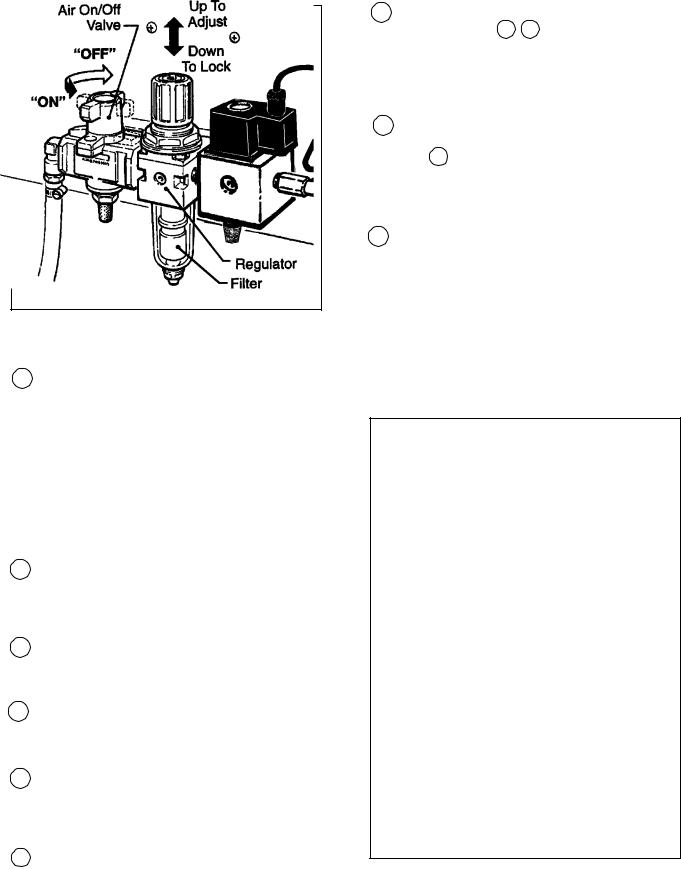
2Main Air "On/Off" Valve/Pressure Regulator/Filter – Figure 3-3
This set of pneumatic components controls, regulates and filters plant air supply to the two separate control circuits of the case sealer.
"On/Off" Valve – "On" turn to "SUP" – "Off" turn to "EXH".
Note – Turning air supply "Off" automatically bleeds air pressure from the case sealer air circuits.
 WARNING
•To reduce the risk associated with mechanical and electrical hazards:
−Turn electrical and air supply off and disconnect before performing any adjustments, maintenance or servicing the machine or taping heads
Note – The air valve has provisions for lockout/tagout according to plant regulations.
Pressure Regulator regulates main air pressure to the machine to adjust pressure, pull knob up and turn – push down to lock setting.
Filter removes dirt and moisture from plant air before it enters the case sealer pneumatic circuits. If water collects in bottom of bowl, lift up on the valve on the
bottom of bowl to drain.
17
Operation (Continued)
Figure 3-3 – "On/Off" Valve/Regulator/Filter
3Emergency "Stop" Switch
The two emergency "Stop" switches are mounted for operator convenience, on both sides of the case sealer. Pushing either of these switches will stop the drive motors/belts and exhaust air from the flap kicker.
To restart machine, rotate emergency stop switch (release switch latch) and then restart machine by pressing green (On) button on side guard.
4Height Adjustment Crank, Upper Taping Head
Raises and lowers upper taping head/flap folders to accommodate box height.
5Width Adjustment Crank
Adjusts distance between side drive belts to accommodate box width.
6Top Flap Compression Rollers
Rollers adjust to properly maintain box width/ top flap center seam for tape seal.
7Indicator, Air Pressure
The optical warning indicator, located on the upper flap folder frame, indicates "Red" when compressed air circuit is on.
8Box Gate Air Pressure Regulator
Adjusts lifting force of the box gate depending on the weight of boxes being sealed.
9 Gate Cams Figure 3-4
The gate cams A B control the rate of box entry into the case sealer. Depending on box size, gate cams can be adjusted to increase production rate. See "Adjustments – Gate Operation".
10Kicker Cam Figure 3-4
The minor flap folder, controlled by the kicker cam C , closes the trailing minor flap on the box. The kicker cam must be adjusted according to the length of the box being sealed. See "Operation" Figure 3-8.
11Pocket, Instruction Manual
A pocket is provided inside the right door for storage of the machine instruction manual. Keep the manual in this pocket for the convenience of machine operators.
Figure 3-4 – Gate/Kicker Cams
18

Operation (Continued)
 WARNING
•To reduce the risk associated with mechanical and electrical hazards:
−Turn electrical and air supply off and disconnect before performing any adjustments, maintenance or servicing the machine or taping heads
•To reduce the risk associated with impact hazards:
−Turn air supply off and be sure flap kicker is down before servicing
−Never operate this equipment with safety interlocks or guarding removed
•To reduce the risk associated with sharp blade hazards:
−Keep hands and fingers away from tape cutoff blades under orange blade guards. The blades are extremely sharp
•To reduce the risk associated with pinch and entanglement hazards:
−Do not leave the machine running while unattended
−Never attempt to work on any part of the machine, load tape, or remove jammed boxes from the machine while the machine is running
−Keep hands, hair, loose clothing, and jewelry away from moving belts, taping heads, and flap kicker
Tape Loading/Threading – Upper Taping Head
See Section II
Tape Loading/Threading – Lower Taping Head With Tape Drum On Taping Head
See Section II
Tape Loading/Threading – Lower Taping Head With Alternate Outboard Tape Drum
 WARNING
•To reduce the risk associated with muscle strain:
−Use proper body mechanics when removing or installing taping heads that are moderately heavy or may be considered awkward to lift
1.Raise upper taping head high enough to allow clearance for removing lower taping head.
2.Remove lower taping head from machine bed and install threading needle as explained in Section II.
3.Replace taping head back into machine.
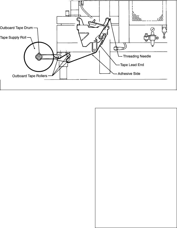
4.Place tape roll on outboard tape drum with adhesive side down on lead end of tape. (Seat tape roll fully against back flange of tape drum.) Thread tape through outboard tape rollers as shown in Figure 3-5 and adhere tape lead end to lower end of threading needle.
5.Complete tape threading as explained in Section II.
19
Operation (Continued)
Figure 3-5 – Tape Threading With Alternate Outboard Tape Drum
Box Size Set-Up
Figure 3-6
Open the side drive belts and raise the upper head assembly to accommodate the desired box width and height.
Move the compression rolls as wide as possible.
Figure 3-6 – Box Size Set-Up
20

Operation (Continued)
 WARNING
•To reduce the risk associated with mechanical and electrical hazards:
−Turn electrical and air supply off and disconnect before performing any adjustments, maintenance or servicing the machine or taping heads
Figure 3-7
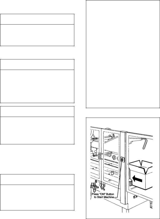
Place a product filled box 55 to 65 mm [2-1/4 to 2-1/2 inches] into the exit end of the machine with the top flaps folded as shown.
Crank the upper head down until is just contacts the top of the box.
Crank the side drive belts in until the belts firmly grip the box.
Figure 3-8
Set Kicker cam relative to length of box being sealed. Measure the distance "X" as shown and set the cam to the same dimension measured on the box. (This dimension provides a good starting point for setting the kicker cam.)
Note: 5 mm hex key wrench is supplied with machine and should be kept in wrench holder on side of upper frame. See Figure 3-1.
Figure 3-7 – Box Size Set-Up
Figure 3-8 – Box Size Set-Up
21
Operation (Continued)
Figure 3-9
 WARNING
•To reduce the risk associated with pinch, entanglement, and impact hazards:
−Keep away from moving belts and pneumatically controlled kicker
Place box at infeed end of machine and push into machine until it is taken away by drive belts.
 CAUTION
•To reduce the risk associated with pinch, entanglement, and impact hazards:
−Keep hands clear of the upper head support assembly as boxes are transported through the machine
−Keep hands, hair, loose clothing, and jewelry away from moving belts and taping heads
 WARNING
•To reduce the risk associated with mechanical and electrical hazards:
−Turn electrical and air supply off and disconnect before performing any adjustments, maintenance or servicing the machine or taping heads
Figure 3-10
Adjust compression rollers. Run box through machine and stop when adjacent to compression rollers. Move compression rollers in to press box top flaps firmly together. Restart machine to exit box.
 CAUTION
•To reduce the risk associated with pinch hazards:
−Keep hands, hair, loose clothing, and jewelry away from box compression rollers when box is passing through machine
Figure 3-9 – Box Size Set-Up
Figure 3-10 – Box Size Set-Up
22
 Loading...