


3M Occupational Health and Environmental Safety Division
3M Center, Building 0235-02-W-70 St. Paul, MN 55144-1000
Printed in USA
© 3M 2011. All rights reserved.
3M and Speedglas are trademarks of 3M Company, used under license in Canada Kevlar is a trademark of E.I. du Pont de Nemours and Company.
3M Occupational Health
and Environmental Safety Division 3M Canada Company
P.O. Box 5757 London, Ontario N6A 4T1 Printed in USA
© 3M 2011. All rights reserved.
3M and Speedglas are trademarks of 3M Company, used under license in Canada Kevlar is a trademark of E.I. du Pont de Nemours and Company.
Division des produits d’hygiène industrielle et de sécurité environnementale de 3M Compagnie 3M Canada
C.P. 5757
London (Ontario) N6A 4T1 ImprimŽ au Canada.
© 3M, 2011. Tous droits rŽservŽs.
3M et Speedglas sont des marques de commerce de 3M, utilisŽes sous licence au Canada. Kevlar est une marque dŽposŽe dÕE.I. duPont de Nemours and Company.
3M México S.A. de C.V.
Av. Santa Fe No. 190
Col. Santa Fe, Del. çlvaro Obreg—n MŽxico D.F. 01210
Impreso en EUA.
© 3M 2011. Todos los derechos reservados.
3M y Speedglas son marcas comerciales de 3M Company, usadas bajo licencia en Canad‡. Kevlar es una marca comercial de E.I. du Pont de Nemours and Company.
98-0060-0194-9/1
34-8706-8887-5
9100 FX
Welding Helmet User Instructions
Directives d’utilisation pour le masque pour soudeurs Instrucciones de la Careta para soldadura
IMPORTANT: Before use, the wearer must read and understand these User Instructions. Keep these User Instructions for reference.
IMPORTANT : Avant de se servir du produit, lÕutilisateur doit lire et comprendre les prŽsentes directives d’utilisation. Conserver ces directives d’utilisation ˆ titre de rŽfŽrence.
IMPORTANTE: Antes de usar el producto, el usuario debe leer y entender estas Instrucciones. Conserve estas Instrucciones para referencia futura.

Table of Contents |
|
System Description ............................................................................................................................... |
1 |
Warnings and Cautions ......................................................................................................................... |
1 |
Limitations of Use ................................................................................................................................. |
2 |
SpeciÞcations ....................................................................................................................................... |
2 |
Operating Instructions........................................................................................................................... |
4 |
Helmet Adjustment ...................................................................................................................... |
4 |
ADF Function............................................................................................................................... |
9 |
System Components and Replacement Parts ...................................................................................... |
13 |
System Inspection and Maintenance ................................................................................................... |
16 |
Cleaning and Storage.......................................................................................................................... |
23 |
Disposal.............................................................................................................................................. |
23 |
Warranty .............................................................................................................................................. |
23 |
For More Information ........................................................................................................................... |
23 |
SYSTEM DESCRIPTION
These User Instructions are applicable to the 3Mª Speedglasª Welding Helmet, 9100 FX. The 3M Speedglas Welding Helmet, 9100 FX with auto-darkening Þlter (ADF), is designed to help protect the wearerÕs eyes from harmful radiation including visible light, ultra-violet radiation (UV) and infrared radiation (IR) resulting from certain arc, plasma and gas welding/cutting processes when used in accordance with these User Instructions. Three sensors on the front of the auto-darkening Þlters (ADFs) react independently at the moment the welding arc is struck and cause the Þlter to darken. The ADF switches back to the light shade after the welding arc
has stopped. Two lithium batteries are used as the power source. Protection from ultra-violet radiation (UV) and infrared radiation (IR) is continuous, whether the ADF is in the light or the dark state due to the protective purple lens coating known as a bandpass Þlter. In the event of battery or electronic failure, the welder remains protected against UV and IR radiation equivalent to the darkest shade setting (shade 13).
These welding helmets offer a clear wideview polycarbonate lens that is ideal for precision weld preparation under a variety of lighting conditions. The clear lens meets ANSI Z87.1-2010 and CSA Z94.3 requirements
for high impact eye and face protection and provides limited protection against certain ßying particles. To use the clear lens, the user simply lifts up the spring-mounted welding shield, which holds the auto-darkening welding Þlter (ADF) securely in a raised position for weld preparation. The spring-mounted welding shield must be returned to the down position prior to welding.
LISTING OF WARNINGS WITHIN THESE USER INSTRUCTIONS
WWARNING
¥Do not use any welding product without appropriate training. For proper use, see supervisor or User Instructions or call 3M in U.S.A.1-800-243-4630. In Canada, call Technical Service at 1-800-267-4414.
¥The 3M Speedglas Welding Helmet, 9100 FX has passed the requirements of the ANSI Z87.1-2010 and CSA Z94.3 for ignition resistance. However, under certain circumstances, these products may support a ßame. Users must evaluate hazards in the workplace and take appropriate precautions for those hazards. 3M does not recommend the use of these products in areas where contact with an open ßame is possible. Improper use may result in injury or death.
¥Always wear ANSI Z87.1 compliant safety spectacles in addition to any welding headgear. Failure to do so may result in permanent eye injury and vision loss. In Canada, users should follow CSA Z94.3 and/or the eyewear requirements of the authority having jurisdiction in their region.
¥Never modify or alter this welding helmet. Repair or replace parts only with approved 3M components. Utilizing components other than those supplied by 3M may adversely affect the performance of the welding helmet and may result in serious injury or death.
¥This headgear must not be painted or cleaned with solvents. Any decals applied to the headgear must be compatible with the surface material and known not to affect adversely the characteristics of the materials used in the headgear. Decals may affect the ßammability characteristics of this headgear.
¥Any headgear subjected to severe impact should be replaced.
¥The SideWindows should be covered with the cover plates in situations when other welders are working beside you and in situations where reßected light can pass through the SideWindows.
WWARNING
¥Should the 3Mª Speedglasª Auto Darkening Filter (ADF) fail to switch to dark mode upon striking an arc, stop welding immediately and inspect the ADF as described in these User Instructions. Continued use of an ADF that fails to switch to the dark state may result in permanent eye injury and vision loss. If the problem cannot be identiÞed and corrected, do not use the ADF; contact your supervisor, distributor or 3M for assistance.
¥Carefully inspect the complete 3M Speedglas 9100 Welding Filter before each use. Cracked, pitted or scratched Þlter glass or protection plates reduce vision and can seriously impair protection. All damaged components should be replaced immediately. Remove any protective Þlm from the visor.
¥The 3M Speedglas Welding Helmet, 9100 FX is not designed for heavy duty overhead welding/cutting operations due to the risk of burns from falling molten metal. Use of this product for these applications may result in serious injury or death.
¥The 3M Speedglas Welding Helmet, 9100 FX (used with 3M Speedglas Series 9100 ADFs) are not suitable for laser welding or welding processes that require shade 14 or higher Þlters. Use of this product for these applications may result in permanent eye injury and vision loss.
¥Only operate the ADF at temperatures between 23¡F (Ð5¡C) and 131¡F (+55¡C). If used outside of this range, the Þlter may not perform as designed and may result in permanent eye injury and vision loss.
CAUTION:
Dispose of equipment that has reached its intended service life in accordance with local regulations.
LIMITATIONS OF USE Important Use Limitations:
¥These products do not provide any protection from respiratory hazards that may result from welding processes or from other sources. 3M Speedglas Helmet 9100 FX Series may be worn in conjunction with certain respirator models. For more information about respiratory protection for welders, contact 3M Technical Service at 1-800-243-4630. In Canada, call Technical Service at 1-800-267-4414.
Note: The 3M Speedglas Welding Helmet, 9100 FX contains no component made from natural rubber latex.
SPECIFICATIONS
Eye and face protection |
Meets ANSI Z87.1-2010, high impact |
|
requirements and CSA Z94.3 |
Head top impact |
Nonedoes not offer head top impact protection |
Operating Temperatures |
23¡F to 131¡F (-5¡C to 55¡C) |
1 |
2 |
Table 1. Specifications for 3M™ Speedglas™ Welding Helmets
|
9100 FX-V |
|
9100 FX-X |
|
9100 FX-XX |
Technical Data |
Welding Helmet |
|
Welding Helmet |
|
Welding Helmet |
|
|
|
|
|
|
Viewing Area |
1.8 x 3.7 in |
|
2.1 x 4.2 in |
|
2.8 x 4.2 in |
(45 x 93 mm) |
|
(54 x 107 mm) |
|
(72 x 107 mm) |
|
|
|
|
|||
|
|
|
|
|
|
Battery Life (2 x CR-2032) (min.) |
2,800 hours |
|
2,500 hours |
|
2,000 hours |
|
|
|
|
|
|
Solar Assist |
Yes |
|
Yes |
|
No |
|
|
|
|
|
|
9100 FX Weight Comp. Assy w/ |
|
|
|
|
|
SideWindows (approx.) |
19.1oz (550g) |
|
19. 8 oz (560g) |
|
20.6 oz (585g) |
|
|
|
|
|
|
Dark Shades |
|
Shades 5, 8, 9, 10, 11, 12, 13 |
|
||
|
|
|
|
|
|
Light State |
|
|
Shade 3 |
|
|
|
|
|
|
|
|
Switching Speed |
|
|
< 0.1 ms (+23¡C) |
|
|
|
|
|
|
|
|
Special Modes |
|
|
Grind, Tack, Lock-in |
|
|
|
|
|
|
|
|
Sensitivity Modes |
|
|
5 levels |
|
|
|
|
|
|
|
|
TIG Rating |
|
|
> 1 Amp |
|
|
|
|
|
|
|
|
Number of Sensors |
|
|
3 (2 eye-level, 1 center) |
|
|
|
|
|
|
|
|
Delay (Recovery) |
|
|
Adjustable 40 - 1300 ms |
|
|
|
|
|
|
||
Temperature Range |
|
23¡F to 131¡F (-5¡C to 55¡C) |
|
||
|
|
||||
Standards Compliance |
ANSI Z87.1-2010 & CSA Z94.3-2007 |
||||
|
|
|
|
|
|
Warranty |
|
|
2 Years |
|
|
|
|
|
|
|
|
Head sizes |
|
6 |
|
|
|
|
|
|
|
|
|
Shield |
|
|
PPA |
|
|
|
|
|
|
|
|
Silver Front and ADF Housing |
|
|
Nylon |
|
|
|
|
|
|
|
|
Headband |
|
|
Nylon, PP, PE, TPE |
|
|
|
|
|
|
|
|
SideWindows |
|
|
Polycarbonate |
|
|
|
|
|
|
|
|
Protection Plates |
|
|
Polycarbonate |
|
|
|
|
||||
Flame Resistant Fabric |
75% Cotton, 25% Kevlar¨ synthetic Þber |
||||
|
|
|
|
|
|
OPERATING INSTRUCTIONS
WWARNING
The 3Mª Speedglasª Welding Helmet, 9100 FX has passed the requirements of the ANSI Z87.1-2010 and CSA Z94.3 for ignition resistance. However, under certain circumstances, these products may support a ßame. Users must evaluate hazards in the workplace and take appropriate precautions for those hazards. 3M does not recommend the use of these products in areas where contact with an open ßame is possible.
Improper use may result in injury or death.
The SideWindows should be covered with the cover plates in situations when other welders are working beside you and in situations where reßected light can pass through the SideWindows.
The 3M Speedglas Welding Helmet, 9100 FX is not designed for heavy duty overhead welding/cutting operations due to the risk of burns from falling molten metal. Use of this product for these applications may result in serious injury or death.
Always wear ANSI Z87.1 compliant safety spectacles in addition to any welding headgear. Failure to do so may result in permanent eye injury and vision loss. In Canada, users should follow CSA Z94.3 and/or the eyewear requirements of the authority having jurisdiction in their region.
Unpacking
Inspect the package contents for shipping damage and ensure all components are present. The product should be inspected before each use following the procedures in the Inspection section of these User Instructions.
Helmet Adjustment
Note: The following adjustments should be made to help ensure that the 3M Speedglas Welding Helmet, 9100 FX is properly adjusted and fitted prior to use.
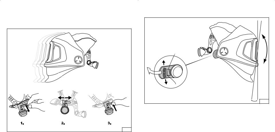
1)Place the 3M Speedglas Welding Helmet, 9100 FX on the head and tighten the ratchet on the back of the headgear (Fig.1) until a comfortable, but secure Þt is achieved. If a comfortable Þt can not be
achieved using the ratchet alone, use the coarse adjustment of the front headband where the L, M, and S adjustment are as shown in the bottom of Fig. 1. L refers to a larger head circumference, M is for a medium head circumference and S is for a smaller head circumference. Adjust the course adjustment
based on head circumference, and then replace the helmet on the head and tighten the ratchet to achieve a comfortable but secure Þt. For additional adjustment, the ratchet may also be turned 180 degrees to achieve a slightly different Þt based on position as shown in Fig. 2.
2)The two top, crown straps should be adjusted to assure that the weight of the helmet is distributed and carried evenly on the top of the head. With the helmet on, and the ratchet tightened, check to make sure that both crown straps are adjusted so that there is no excess space or gaps between the top of the head, and the crown straps. At times, the back crown strap may be too large and cause a gap, but this is not
an appropriate manner for wearing the helmet. If there is an excessive gap, adjust the crown straps by sliding and tightening as shown in Fig. 1. If there is no gap, but the helmet feels as though it is too high on the head, loosen the crown straps until a comfortable height is achieved.
3 |
4 |

Fig. 1 |
5 |
Fig. 2 |
6 |
3)Next, the front-to-back, or fore/aft position of the helmet, should be adjusted so that the helmet is a comfortable distance from your face, but not touching your nose or face. The front-to-back adjustment can be achieved by moving the slide adjustments in the headgear which also moves the helmet back and forth as shown in Fig. 3. It is a good idea to make sure that the settings on both sides of the slide adjustment are at the same position to help with balance and overall comfort.
Fig. 3 |
7 |
4)With the helmet on the head, adjust the vertical viewing angle as shown in Fig. 4 to optimize the viewing area and position of the helmet relative to the workplace application.
Fig. 4
8
ADF Function
WWARNING
Should the 3Mª Speedglasª Auto Darkening Filter (ADF) fail to switch to dark mode upon striking an arc, stop welding immediately and inspect the ADF as described in these User Instructions. Continued use of
an ADF that fails to switch to the dark state may result in permanent eye injury and vision loss. If the problem cannot be identiÞed and corrected, do not use the ADF; contact your supervisor, distributor or 3M for assistance.
The 3M Speedglas Welding Helmet, 9100 FX (used with 3M Speedglas Series 9100 ADF) is not suitable for laser welding or welding processes that require shade 14 or higher Þlters. Use of this product for these applications may result in permanent eye injury and vision loss.
Only operate the ADF at temperatures between 23¡F (Ð5¡C) and 131¡F (+55¡C). If used outside of this range, the Þlter may not perform as designed and may result in permanent eye injury and vision loss.
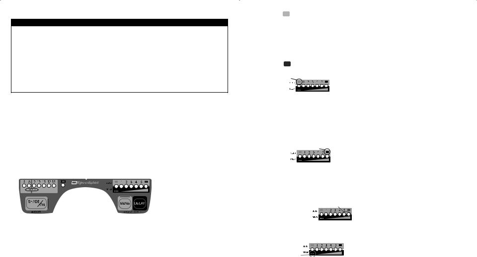
On/Off
To activate the ADF, press the SHADE/ON button. The ADF automatically turns OFF after 1 hour of inactivity. The ADF has three photo sensors that react independently and cause the Þlter to darken when a welding arc is struck. The ADF may not turn dark if the sensors are blocked or the welding arc is totally shielded. Flashing light sources (e.g. safety strobe lights) can trigger the ADF making it ßash when no welding is occurring. This interference can occur from long distances and/or from reßected light. Welding areas must be shielded from such interference.
Shade
Seven different shade settings are available, split into two groups, 5, 8 and 9-13. In order to see the current shade setting, momentarily press the SHADE/ON button. To change shade, press the SHADE/ON button repeatedly. Move the ßashing LED to the desired shade. To shift between the two shade groups (shade 5, 8) and (shade 9-13); hold the SHADE/ON button down for 2 seconds. In all welding processes the arc should only be viewed with the recommended dark shade (Table 2).
Sensitivity Selection
The programming and sensitivity of the photo detector system can be adjusted to accommodate a variety of welding processes and workplace conditions. To change the sensitivity setting, press the SENS button repeatedly until the LED shows the desired setting.
9
Position |
Light-State Lock (Grinding Mode) Ð switching function is disabled, remains in |
|
constant shade 3. |
Position 1 |
Least sensitive setting. Used if there is interference from other weldersÕ arcs in |
|
the vicinity. |
Position 2 |
Default setting. Used for most types of welding, indoors and outdoors. |
Position 3 |
For welding with stable welding arcs (e.g., TIG welding). |
Position 4 |
For low current TIG welding or inverter-type welding machines. |
Position 5 |
For TIG welding where part of the arc is obscured from view. |
Position |
Dark-State Lock Ð switching function is disabled, remains in selected dark |
|
shade. |
Light-State Lock
This setting is intended for grinding or other non-welding activities. When the ADF is locked in the light state (shade 3) the LED under the symbol will ßash every 8 seconds to alert the user. The ADF must be changed to an appropriate SENS setting before arc welding or it will remain in the light-state lock mode. When the ADF turns off (after 1 hour inactivity), it will automatically return to the default sensitivity setting 2.
Position 1-5
If the Þlter does not darken during welding as desired, increase the sensitivity until the ADF switches reliably. Should the sensitivity be set too high, the Þlter may remain in the dark state after welding is complete due
to ambient light. In this case, adjust the sensitivity downward to a setting where the ADF both darkens and lightens appropriately.
Dark-State Lock
This setting locks the ADF in the selected dark shade. If the ADF turns off (after 1 hour inactivity), it will automatically return to the default sensitivity setting 2.
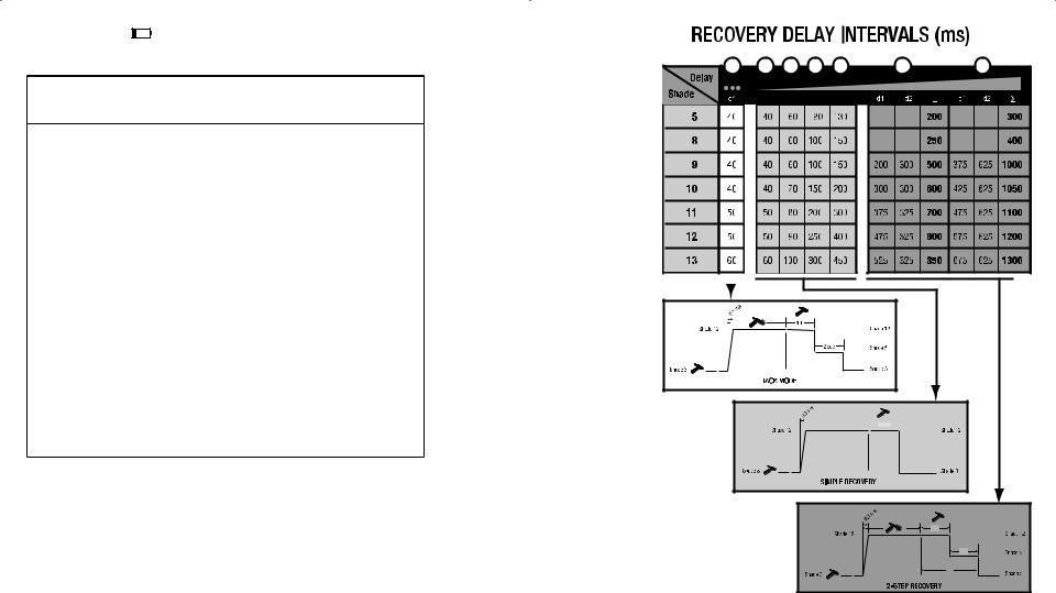
Delay
The delay function allows the user to manually increase or decrease the recovery delay time (from dark to light) according to the requirements of the welding process. The recovery time intervals are also automatically extended as the shade increases. The time intervals are listed in milliseconds in Table 3. Although the Delay and Sensitivity functions share the same LED display, they are separate adjustments.
2-Step Recovery
The two longest delay settings include an intermediate stage in the recovery. As the arc extinguishes, the Þlter will brießy recover to shade 5 and then to shade 3. The time intervals for each stage are listed as d1 and d2 in Table 3.
Tack Mode
This setting may help reduce eye fatigue resulting from the eye frequently adjusting to differing light levels during rapid tack welding. As the arc extinguishes, the Þlter will recover to shade 5. If another arc is not struck within 2 seconds the Þlter will return to the normal light state (shade 3).
10
Low Battery Indicator
The batteries should be replaced when the low battery indicator ßashes or LEDs do not ßash when the buttons are pressed.
Table 2. Recommended Guide for Shade Numbers (Adapted from ANSI Z49.1-2003)
|
Electrode |
Arc |
Minimum |
Recommended |
|
|
|
|
|
|
|
|
diameter |
current, |
Protective |
Shade |
|
|
|
|
|
|
|
Operation |
inches |
amps |
Shade |
Number |
|
|
|
|
|
|
|
Shielded metal arc |
< 3 |
< 60 |
7 |
--- |
|
|
|
|
|
|
|
|
3-5 |
60-160 |
8 |
10 |
|
|
|
|
|
|
|
|
5-8 |
160-250 |
10 |
12 |
|
|
|
|
|
|
|
|
> 8 |
250-550 |
11 |
14 |
|
|
|
|
|
|
|
Gas-metal-arc welding |
|
< 60 |
7 |
--- |
|
|
|
|
|
|
|
|
|
60-160 |
10 |
11 |
|
|
|
|
|
|
|
|
|
160-250 |
10 |
12 |
|
|
|
|
|
|
|
|
|
250-500 |
10 |
14 |
|
|
|
|
|
|
|
Gas-tungsten-arc |
|
< 50 |
8 |
10 |
|
|
|
|
|
|
|
|
|
|
|
|
|
|
|
||||
|
|
50-150 |
8 |
12 |
|
|
|
|
|
|
|
|
|
150-500 |
10 |
14 |
|
|
|
|
|
|
|
Air-carbon-arc cutting |
|
< 500 |
10 |
12 |
|
|
|
|
|
|
|
|
|
500-1000 |
11 |
14 |
|
|
|
|
|
|
|
Plasma-arc welding |
|
< 20 |
6 |
6-8 |
|
|
|
|
|
|
|
|
|
20-100 |
8 |
10 |
|
|
|
|
|
|
|
|
|
100-400 |
10 |
12 |
|
|
|
|
|
|
|
|
|
400-800 |
11 |
14 |
|
|
|
|
|
|
|
Plasma-arc cutting |
|
< 300 |
8 |
9 |
|
|
|
|
|
|
|
|
|
300-400 |
9 |
12 |
|
|
|
|
|
|
|
|
|
400-800 |
10 |
14 |
|
|
|
|
|
|
|
Carbon arc welding |
|
|
|
14 |
|
|
|
|
|
|
|
11


 delay
delay 

d 1
d 2
∑
Table 3
12
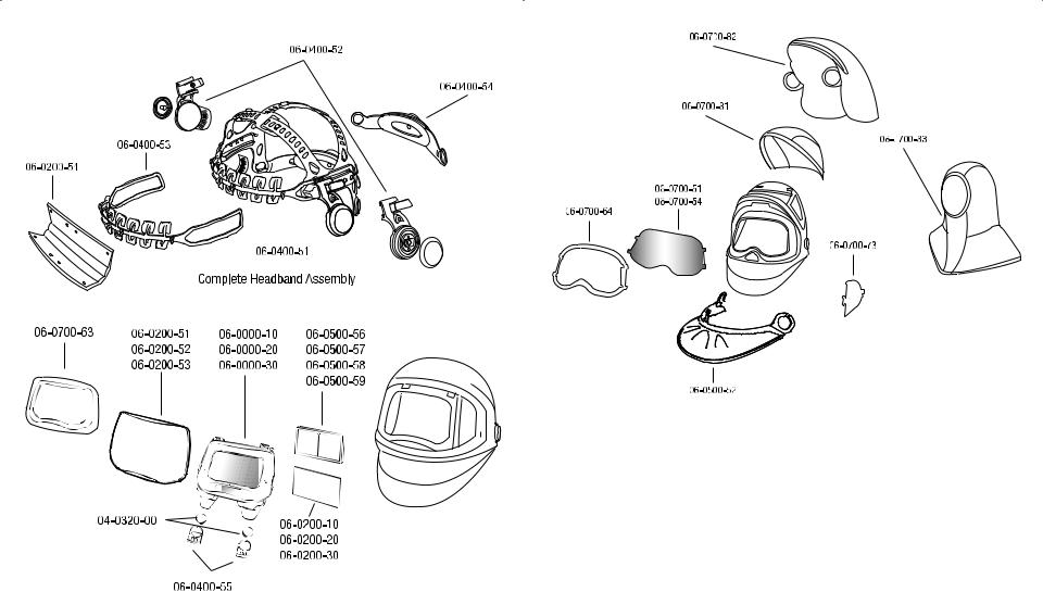
3M™ SPEEDGLAS™ SYSTEM COMPONENTS AND REPLACEMENT PARTS
|
|
|
13 |
14 |
|

3M™ Speedglas™ Complete Helmet Assemblies
06-0600-10SW |
Welding Helmet 9100 FX SideWindows with ADF 9100V |
06-0600-20SW |
Welding Helmet 9100 FX SideWindows with ADF 9100X |
06-0600-30SW |
Welding Helmet 9100 FX SideWindows with ADF 9100XX |
3M™ Speedglas™ Replacement Parts and Accessories |
|
04-0320-00 |
Batteries (CR-2032) |
06-0000-10 |
ADF 9100V |
06-0000-20 |
ADF 9100X |
06-0000-30 |
ADF 9100XX |
06-0200-10 |
Inside Protection Plate 9100V (5 pack) |
06-0200-20 |
Inside Protection Plate 9100X (5 pack) |
06-0200-30 |
Inside Protection Plate 9100XX (5 pack) |
06-0201-10 |
Starter Kit 9100V (5 Outside & 2 Inside Protection Plates, 1 sweatband) |
06-0201-20 |
Starter Kit 9100X (5 Outside & 2 Inside Protection Plates, 1 sweatband) |
06-0201-30 |
Starter Kit 9100XX (5 Outside & 2 Inside Protection Plates, 1 sweatband) |
06-0200-51 |
Outside Protection Plate 9100, Standard |
06-0200-52 |
Outside Protection Plate 9100, Scratch Resistant |
06-0200-53 |
Outside Protection Plate 9100, High Temperature |
06-0200-54 |
Sweatband 9100 |
06-0400-51 |
Headband Assembly 9100 Complete (headgear) |
06-0400-52 |
Pivot Mechanism 9100 (Left & Right) |
06-0400-53 |
Headband 9100 Front Part |
06-0400-54 |
Headband 9100 Back Part (ratchet adjuster) |
06-0400-55 |
Battery Holder 9100 |
06-0500-51 |
Head Protector 9100, Tecaweld |
06-0500-52 |
Ear and Neck Protector 9100, Tecaweld |
06-0500-54 |
Welding Beanie Hat, (no visor) |
06-0500-55 |
Welding Cap with Visor |
06-0500-56 |
MagniÞcation Plate 1.5X |
06-0500-57 |
MagniÞcation Plate 2.0X |
06-0500-58 |
MagniÞcation Plate 2.5X |
06-0500-59 |
MagniÞcation Plate 3.0X |
06-0500-60 |
Cloth Storage Bag |
06-0500-61 |
Branded Toolbox Decal |
|
15 |
06-0700-51 |
Wideview Clear Grinding Visor, Standard |
06-0700-54 |
Wideview Clear Grinding Visor, Anti-Fog |
06-0700-63 |
Chrome Front Panel, 9100 FX |
06-0700-64 |
Wideview Clear Grinding Visor Frame, 9100 FX |
06-0700-73 |
SideWindow Covers, 9100 FX |
06-0700-81 |
Standard Headcover, 9100 FX |
06-0700-82 |
Extended Headcover (Head and Neck), 9100 FX |
06-0700-83 |
Full Hood, Black |
SYSTEM INSPECTION AND MAINTENANCE
WWARNING
Never modify or alter this welding helmet. Repair or replace parts only with approved 3M components. Utilizing components other than those supplied by 3M may adversely affect the performance of the welding helmet and may result in serious injury or death.
This headgear must not be painted or cleaned with solvents. Any decals applied to the headgear must be compatible with the surface material and known not to affect adversely the characteristics of the materials used in the headgear. Decals may affect the ßammability characteristics of this headgear.
Carefully inspect the complete 3Mª Speedglasª Welding Filter, 9100 before each use. Cracked, pitted or scratched Þlter glass or protection plates reduce vision and can seriously impair protection. All damaged components should be replaced immediately. Remove any protective Þlm from the visor.
Any headgear subjected to severe impact should be replaced.
Inspect the welding helmet and headgear for any worn or damaged parts. Replace any worn or damaged parts utilizing those components listed in the replacement parts and accessories list contained in this User Instruction.
To check for proper ADF operation, hold the ADF within a few inches of a ßuorescent light bulb and observe the ADF switch to the selected dark state. Depending on the light source, it may be necessary to temporarily increase the sensitivity setting. Optionally, the ADF can be triggered by pointing any electronic device remote control (e.g. television) at the ADF sensors and by pushing the ÒOnÓ button.
Note: If the ADF does not function as described in these User Instructions, do not use and immediately contact your supervisor or 3M representative.
16
Sweatpad Replacement
See Fig. 5.
Fig. 5 |
Silver Frame, Outer Protection Plate, and ADF Removal and Replacement
See Fig. 6.
1 |
2 |
3 |
4 |
5 |
6 |
7 |
8 |
Fig. 6
17 |
18 |
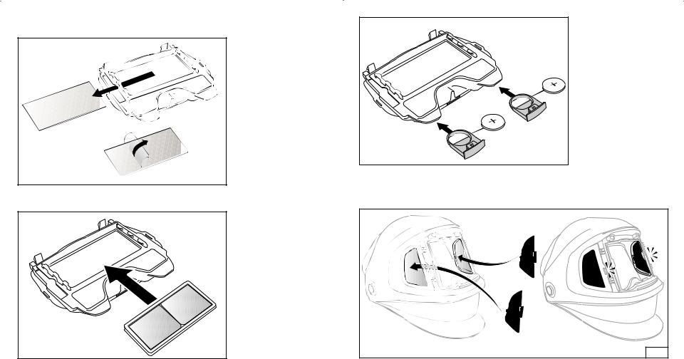
Inside Protection Plate, Batteries Replacement and Magnifying Lens Installation
See Figs. 7 through 9.
Fig. 7 Inside Protection Plate
Fig. 8 Magnification Plate
Fig. 9 Battery
Installation of SideWindow Coverplates
See Fig. 10.
Fig. 10
19 |
20 |
 Loading...