


Dynatel™ 965DSP Series
Subscriber Loop Analyzers
Instruction Manual
Includes Spectrum Analyzer (optional)
and Active ADSL Modem (optional)
June 2005
78-8130-7429-7-F

Welcome to the Instruction Manual for the 3M™ Dynatel™ 965DSP Series of Subscriber Loop Analyzers. The 965DSP Series includes the 965DSP, 965DSP/ADSL, 965DSP/SA and 965DSP/ADSL/SA Loop Analyzers.
This document will give you a brief overview of the products, a description of their test functions, and some technical hints on how to find problems on telecommunications cables.
2

Table of Contents |
|
Out of the Box ....................................................... |
4 |
Front Panel............................................................. |
5 |
Control Keys ..................................................... |
6 |
Editing............................................................... |
6 |
Function Keys ................................................... |
7 |
Welcome ................................................................ |
8 |
Setup (Country, Language, Units, Clock Format, |
|
Set Clock, Set Beep, Autotest Limits, |
|
Printer, Power Down Timeout, Edit Wire |
|
Gauge, Voltage Termination, User Info)...9 |
|
Functions |
|
Contrast/Backlight .......................................... |
20 |
Help ................................................................ |
21 |
High Voltage ........................................... |
21 |
Voltage ............................................................ |
22 |
Current ............................................................ |
23 |
Resistance ....................................................... |
24 |
Soak Test......................................................... |
25 |
Toolbox ........................................................... |
26 |
Self Calibrate .......................................... |
27 |
Load Coils............................................... |
28 |
Kick Test................................................. |
29 |
Stored Results......................................... |
30 |
ADSL Results......................................... |
33 |
Caller ID ................................................. |
36 |
Special Resistance .................................. |
38 |
Ground Resistance.................................. |
39 |
Ohms/Distance........................................ |
40 |
K-Test...................................................... |
41 |
Ringers.................................................... |
50 |
Splice Locate .......................................... |
51 |
Opens .............................................................. |
52 |
Tone ................................................................ |
55 |
RFL ................................................................ |
58 |
DSL ................................................................ |
71 |
TDR ................................................................ |
93 |
dB (Loss, Noise, Long. Balance |
|
Wideband Loss, Level Trace).................. |
106 |
Autotest......................................................... |
110 |
Talk Set Setup............................................... |
136 |
Care and Maintenance ....................................... |
137 |
Specifications..................................................... |
141 |
POTS Criteria (US and Canada)........................ |
143 |
Self-Test Board .................................................. |
144 |
Warranty Information......................................... |
146 |
3

Out of the Box
What you will find when you unpack the shipping box:
•3M™ Dynatel™ 965DSP Series Subscriber Loop Analyzer
•Carrying case
•NiMH battery pack (inside the 965DSP)
•Spare battery holder
•Test Leads (red/black pair, blue/yellow pair, green)
•Shorting strap
•AC charger
•Power cord
•Instruction manual
•Quick card and Warranty card
•Self-test board
Visually inspect all components. If any component is missing or appears damaged, do not install and call customer service at 1-800-426-8688 for a replacement product.
The Dynatel 965DSP comes in the carrying case and should remain in the case to give extra protection from shock and the environment.
A NiMH battery pack is already installed in the 965DSP. You may need to charge the battery before using the unit. Please see Care and Maintenance section. The Spare Battery Holder holds six “AA” alkaline batteries and should only be used if the NiMH battery pack is discharged.
The 965DSP comes with 5 test leads: red/black, blue/yellow and green. The Shorting Strap is only used in RFL mode.
The AC charger will convert 110 or 220 Vac into the 12 Vdc used for charging the 965DSP. A North American 110 Vac Power Cord is provided with the unit. The AC charger is meant for charging the NiMH battery pack only. Do not use the AC charger to power the 965DSP during normal operations.
Additional information is also found in the 965DSP help screens. For Technical Service, Warranty or Repair questions call: 800 426 8688 in the US or Canada, or contact your local 3M Representative.
Communication Markets Division
3M Telecommunications
6801 River Place Blvd.
Austin, TX 78726-9000 USA
4

Screen
The 965DSP screen is a graphical LCD (Liquid Crystal Display) that gives high resolution for viewing text and graphics. The screen format is similar to the following for most functions.
Test Leads
The Test Lead icons are shown on each of the measurement screens. Each lead points to a color dot on the front label that corresponds to the actual test lead. The test leads have the labels “RNG” (ring), “GND” (ground) and “TIP” (tip) for the US and Canada. These labels correspond to “B”, Ground, and “A” for other countries.
Keypad
The 965DSP Keypad has twelve yellow and red “Control Keys” and twelve blue “Function Keys”.
5 |

Control Keys
Use the red and yellow keys to control the actions and the setup of the 965DSP and its functions. The active control keys for each function are shown at the bottom of the corresponding 965DSP screen.
Use the [Return] key to return to a previous step in a function.
Use the [Contrast] key to adjust the contrast or to turn the backlight on or off.
Use the [Save] key for savingAutotest results, Single Trace TDR waveforms, andADSL Modem link information (/ADSL option only).
Use the [On/Off] key to turn the 965DSP on or off (see also “Power Down Timeout” on page 16)
Use the [Tab] key to select between different options.
Use the [Setup] key to change the setup of any function.
Use the [Help] key to get help with any screen.
Use the [Enter] key to accept changes or move to the next step in a function.
Use the [Up] and [Down] keys to scroll to different menu options or insert and delete characters when editing.
Use the [Left] and [Right] keys to move between different options or move the TDR cursor.
Editing
Use the following keys when editing:
Use  to insert a space to the left of the cursor. Use
  to delete the character above the cursor.
Use  to add a ‘dash’ in a telephone number or a minus sign for signal levels or temperature.
Use  to add one second delay for dialing.
6
Function Keys
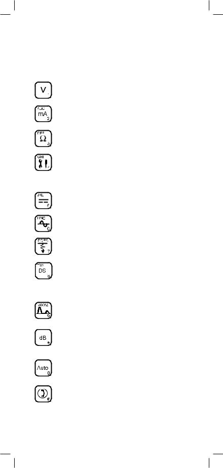
Use the blue keys to select the different test functions in the 965DSP. The blue keys become number or letter keys when editing.
Use the [Voltage] key to measure DC or
AC voltage.
Use the [Current] key to measure loop current.
Use the [Resistance] key to measure resistance.
Use the [Toolbox] key to access: Self-Cal, Load Coils, Kick Test, Ringers, Special and Ground Resistance, K-Test, Ohms/Distance, Stored Results, Caller ID, and Splice Locate.
Use the [Opens] key to find the distance to an ‘open’ circuit.
Use the [Tone] key to send tones for pair identification or measuring loss.
Use the [RFL] key to find the distance to a resistance fault on a pair.
L |
Use the [DSL] key to access: ISDN datalink, |
ADSL modem (/ADSL option only) and DSL |
|
|
parametric measurements/Spectrum Analyzer |
|
(/SA option only). |
Use the [TDR] key to display the Time
Domain Reflectometer.
Use the [dB] key to measure Loss, Noise,
Longitudinal Balance, Wideband Loss, or
Level Trace.
Use the [Auto] key to perform a series of tests on an Active, Inactive or Wideband pair.
Use the [Talk Set] key to dial numbers or to place a phone call on a working pair.
7

Welcome Screen
This is the screen that you see when you first turn on the 965DSP. It shows the model name, installed options, serial number, copyright year, software version, and the selected country. The battery symbol in the upper right-hand corner of the display gives an indication of the approximate battery capacity. Each bar represents one-quarter of the full capacity. If the spare battery holder with the alkaline batteries is installed in place of the NiMH battery pack, the battery level will not be monitored and the battery symbol will not be visible in the display.
Control Keys
Press [Setup] to go to the general setup screen from the Welcome screen.
Use the [Up] and [Down] keys to highlight a menu item: Country, Language, Units, Clock Format, Set Clock, Set Beep, Autotest Limits, Printer, Power Down Timeout, Edit Wire Gauge, Voltage Termination or User Info. Press the [Enter] key to select the highlighted item.
Use [Return] to return to the Welcome Screen without making changes.
8
Country
Use the Country setup to configure the 965DSP for a specific country. Selecting a new country will configure the 965DSP with the setups for language, units, clock format, wire gauges, and cable types for that particular country.
Use the [Up] and [Down] keys to highlight a Country. Use [Enter] to select a country. You will be warned about changing country-specific default values and asked to confirm or cancel your selection.
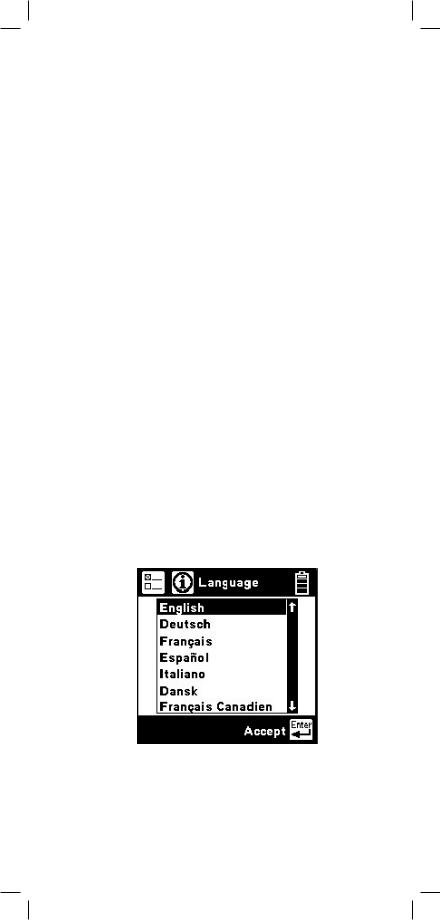
Language
Use the Language setup to change only the language in the 965DSP. Country-specific default values are not affected.
Use the [Up] and [Down] keys to highlight a new language. Use [Enter] to accept the changes and return. Use [Return] to return to the Welcome Screen without making changes.
9
Units
Use the Units setup to change the units of measurement for the 965DSP:
Use the [Up] and [Down] keys to highlight the option. Use the [Tab] key to select the parameter for each unit of measurement.
Distance: Feet or Meters. This affects all distances displayed in the 965DSP.
Degrees: Fahrenheit or Centigrade. This affects all temperatures used in the 965DSP.
Filter: C-Message or CCITT. This affects the filter used in the Noise function. Use the C-Message filter in the US and Canada. Use the CCITT (also called “Psophometric”) filter in all other countries.
The 965DSP also features a dBrnP filter for noise tests in New Zealand. To set the default noise filter to dBrnP, set Filter option to CCITT and Country to New Zealand. This filter is used only in New Zealand; for all other countries, the CCITT option uses a dBrnOp filter. Noise test results will be displayed in dBrnP as shown.
10
TDR: Vp (Velocity of Propagation) or m/µS (meters per microsecond). This affects the TDR “velocity of propagation.” Use “Vp” in the US and Canada.
Use “m/µS” in other countries.
Use the [Enter] key to accept any changes and return. Use the [Return] key to return to the Welcome Screen without making changes.
Clock Format
Use the Clock Format setup to change the format of the clock. The clock is used for the timestamp and datestamp in stored results.
Use the [Up] and [Down] keys to highlight either the date or time. Use the [Tab] key to select the format parameter.
Date: m/d/y (month/day/year) or d.m.y (day.month. year). The m/d/y format is used in the US and Canada. The d.m.y format is used in most other countries.
Time: 12 hours or 24 hours. This affects the number of hours displayed in the clock. The 12 hour clock (with a.m. and p.m.) is used in the US and Canada. The 24 hour clock format is used in most other countries.
Use [Enter] to accept the changes and return. Use [Return] to return to the Welcome Screen without making changes.
11
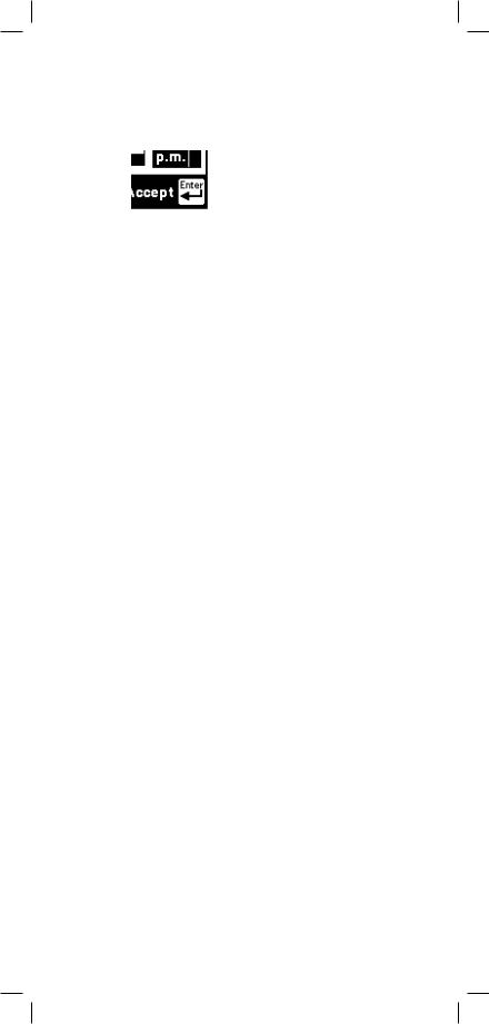
Set Clock
Use the Set Clock setup to change the date and time.
Use the [Tab] key to select either the date, time, or a.m./p.m. Use the [Left] and [Right] keys to select the digit to change. Use the blue keys to enter the values. Use the [Up] and [Down] keys to select a.m. or p.m. Use [Enter] to accept the changes and return. Use [Return] to return to the Welcome Screen without making changes.
Set Beep
Use the Set Beep setup to turn the key beeps on or off.
Use the [Tab] key to toggle between on or off. Use the [Enter] key to return.
12

Autotest Limits
Use the Autotest setup to change the pass/fail threshold values for the Inactive Pair, Active Pair and Wideband Autotests.
Use the [Up] and [Down] keys to highlight the desired Autotest parameters to modify. Press the [Enter] key to select the highlighted choice or press the [Setup] key to restore the factory default values for the selected Autotest.
If Wideband is selected, a list of the available wideband services is displayed. Use the [Up] and [Down] keys to select the wideband service to modify. Press the [Enter] key to select the highlighted choice or press the [Setup] key to restore the factory default values for the selected service.
13

When the Inactive Pair, Active Pair or specific Wideband service is selected, the Threshold Limits screen will be displayed. This screen displays a list of measurements performed in the selected Autotest and the corresponding pass/fail limits for each measurement.
The limits indicate the values at which the measurement result passes (OK), is marginal (Yield Sign) or is unacceptable (Stop Sign). The lower limit threshold value is shown in the box on the left, the upper limit in the box on the right.
If the test result value passes or is unacceptable, the pass/fail result will correspond to the symbol under the box (either Stop or OK). If the test result value is between the upper or lower limit, the pass/fail result will be marginal (Yield Sign).
Use the [Up] and [Down] keys to highlight the desired test. Use the [Tab] key to move the cursor to the limit value and enter the new value using the blue keys. Press the [Setup] key to restore the factory default values for the selected test. Press the [Enter] key to accept the changes or the [Return] key to ignore all changes and return to the Threshold Setup screen. If invalid limits are entered, a warning screen will be displayed. Press the [Enter] key to return to Edit Limits screen and make appropriate changes to the limits.
14

A custom Loss Frequency (sometimes known as the “Nyquist frequency”) can be set for use in the Wideband Autotest. The custom Loss Frequency edit screen is accessed by pressing the [Setup] key from the startup screen, selecting Autotest Limits, then Wideband. Press the [Enter] key to select a service type. Select Loss Frequency, then use the [Tab] key to edit. Enter the frequency value in KHz with the blue numeric keys. Use the [Up] or [Down] arrow keys to add or remove digits.
Printer
Use the Printer option to set the printer output type. Use the [Up] and [Down] arrow keys to select either graphics or text output, then press the [Enter] key to accept your selection and return to the Setup menu.
15

Power Down Timeout
To change the power down timeout, press the [Setup] key from the Welcome screen, then select Power Down Timeout. Use the [Up] and [Down] arrow keys to select the desired timeout period, then press the [Enter] key to set that period as the default. After a period of inactivity equal to the default period, the unit will beep, then automatically power down.
16
Edit Wire Gauge
This function allows you to set up custom wire gauges to be used wherever the set uses a wire gauge menu. Press the [Setup] key from the Welcome screen, use the [Down] arrow key to scroll to Edit Wire Gauge, and then press the [Enter] key to edit.
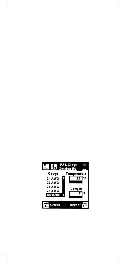
Name the custom configuration Custom 1 or Custom 2 by pressing the [Up] or [Down] arrow key. Use the [Tab] key to select the values to be edited. Use the [Left] and [Right] or [Up] keys to select the digit to change. Use the blue numeric keys to enter the values. Use [Enter] to accept the changes. Press the [Return] key to return to the Setup menu without making changes.
You can select this custom cable from any selection menu (such as RFL), as shown.
17

Voltage Termination (supported countries only)
This option allows you to select the input impedance of the 965DSP digital voltmeter. Press the [Setup] key from the Welcome screen, use the [Down] arrow key to scroll to Voltage Termination, and then press the [Enter] key to select.
The input impedance of the internal 965DSP voltmeter is normally 1Mohm. However, some legacy systems use voltage measurement systems with input impedances of 100Kohms. This option is provided to maintain measurement compatibility with those systems. Use the [Tab] key to select the desired termination and [Enter] to select.
18

If 100Kohm termination is selected, the 965DSP will display ‘100K’ on the voltage measurement screen as indicated below.
User Info
This selection allows you to add optional additional information to your saved records. Press the [Setup] key from the Welcome screen, use the [Down] arrow key to scroll to User Info, and then press the [Enter] key to select.
Enabling User Info will cause the 965DSP to add an extra user-editable screen during the results save process. This screen has edit boxes for the technician identification (‘Tech ID’) and the current Job Number. These fields appear as part of the Saved record when printed or viewed in PCLink.
19

Use the [Tab] key to select ‘ON’ or ‘OFF’ and [Enter] to save your selection. Once the User Info option has been changed, the changes remain in effect until you explicitly change them again.
Contrast/Backlight
Press the [Contrast] key to display the contrast screen. Use the [Up] and [Down] arrow keys to adjust the contrast. Press the [Contrast] key again to turn the backlight on or off. Use the [Enter] key to return.
20
Help
Press the [Help] key at any time in any screen to get help on that function.
Press the [Enter] or [Return] key to return to the previous screen.
High Voltage
This screen indicates that a high voltage (120 Vac/ Vdc or greater) has been detected between the test leads when not in the Voltage Mode. The 965DSP has opened an internal relay to protect itself from damage. Use standard safety practices for
disconnecting the test leads since high voltage may be present.
Press the [Enter] key to restart the 965DSP.
21

Function Keys
Voltage
This function first measures and displays the DC voltage between the red and black test leads.
Press the [Tab] key to move to the next test lead configuration. The highlighted reading is “live” and the non-highlighted readings are the last values.
Press the [Enter] key to switch from the DC to the AC voltage measurement.
Press the [Tab] key to move to the next test lead configuration.
Press the [Enter] key to switch from the AC to the DC voltage measurement.
22

Current
This function measures the DC current flowing through a 430 Ohm resistor inside the 965DSP. Connect the red and black leads to the pair to measure loop current.
If the Current is greater than 110 mA, you will see the following ‘Current Warning’ screen:
This screen indicates that a high current has been detected between the test leads and that the 965DSP has opened an internal relay to protect itself
from damage. Use standard safety practices for disconnecting the test leads. Press the [Enter] key to restart the 965DSP. Fix problems before restarting the current measurement again.
23
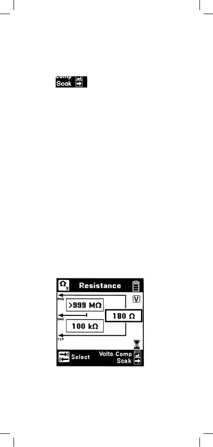
Resistance
This function first measures the resistance between the red and black test leads.
Press the [Tab] key to move to the next test lead configuration.
The “V” in the upper right corner of the screen indicates that the resistance measurement compensates for C.O. voltage on the line.
Press the [Enter] key to remove the voltage compensation. Use this technique only if you have first determined there is no DC voltage on the pair (by using the Voltage function). The noncompensated measurement is slightly faster, but it is not as accurate if there is voltage on the line.
The resistance measurement can be affected by moisture on the test lead clips or terminal face. For the most accurate measurement make sure that these areas are dry.
24

Soak Test
Use the Soak Test function to continuously measure the non-compensated resistance tip to ground and ring to ground simultaneously.
Press the [Right] arrow key to access the Soak test from the Resistance screen. Connect the red and black leads to an inactive pair. Connect green to shield or ground. Use the [Right] arrow key to refresh the measured resistance to the “Snap Shot” area. This measurement will not be accurate if there is foreign voltage or battery cross on the line.
25

Toolbox
The “Toolbox” menu contains a selection of functions depending on the options equipped in the unit and the Country Code selected during Setup (i.e. Caller ID is available only in North America and ADSL Stored Results is only available on /ADSLequipped models). The menu displays only the functions for which the unit is equipped. Only six menu items are visible at any time. Use the [Up] and [Down] arrow keys to move to the desired function, then press the [Enter] key to accept the choice.
Note: The last item in the Toolbox menu (Maintenance) is reserved for use only during Factory setup and service of the 965DSP.
26

Self-Calibration
Use this function to calibrate the 965DSP anytime the outside temperature changes by more than 35°F (20°C), after changing the batteries, or anytime the battery pack completely discharges. Calibrate the 965DSP at the same temperature at which it will be used.
Note: Initiate a self-calibration prior to the very first use of your 965DSP.
You will see the following screen as soon as you select Self-Calibration from the Toolbox.
Short the red, green, black and yellow leads together when prompted, then press [Enter] to continue.
The screen shows “Self-Calibration Complete” when the calibration is done, or “Self-Calibration Failed” if the calibration fails. In this last case, check the test lead connections and try again.
27

Load Coils
This function counts up to five load coils on the pair and determines the distance to the first one. The distance measurement requires that you specify the wire gauge of the pair. This is done in the Load Setup screen. Use the [Up] and [Down] arrow keys to highlight the correct wire gauge. Use [Enter] to accept that choice.
The Load Coils screen will appear and an hour glass will be visible at the bottom of the screen during the measurement. When complete, the load coil count will be visible in the box on the right and the distance to the first load coil will be visible in the box labeled “Nearest Load”. If no load coils are present the count will be 0 and “Not Found” will be visible in the “Nearest Load” box.
Indicates  total number
  of load coils
detected
After the test is done, press the [Enter] key to repeat the load coil count. Press the [Return] key to return to the Toolbox menu or press the [Setup] key to change the wire gauge.
It is not necessary to have any particular length of cable before the first load coil, but you must have at least 3000 feet (1000 meters) of cable after each load coil for the Load Coil function to count properly.
You may also use the TDR function to find the distance to the first load coil on the pair.
28

Kick Test
Use the Kick Test function to continuously measure the voltage, resistance and capacitive length on tipring, ring-ground, and tip-ground. Connect the red and black leads to the selected pair. Connect green to shield or ground.
Press the [Tab] key to move to the next lead configuration. Press the [Return] key to return to the Toolbox menu or press the [Setup] key to change the cable type.
29

Stored Results
Use this function to view previously stored results of the Autotest or TDR function. If no results have been stored, “No Results Stored” will be visible on the screen. If one or more test results have been stored, the ID number for each will be displayed.
Print Results
Press the [Setup] key to display the Print screen.
Press the [Enter] key to print all of the results. Press the [Tab] key to print the results of the selected ID. Press the [Return] key to return to the main Results screen without printing.
30
 Loading...