


3
Dynatel™
Advanced Modular System 965AMS
Version 4.01.17 User’s Guide
Future-Proof Testing Platform
November 2010
78-8135-5011-4-D

Contents |
|
Introduction...................................................................................... |
5 |
Getting Started........................................................................................... |
5 |
Welcome Screen........................................................................................ |
7 |
Help........................................................................................................... |
7 |
High Voltage.............................................................................................. |
8 |
System Setup................................................................................... |
9 |
Country...................................................................................................... |
9 |
Language................................................................................................. |
10 |
Module..................................................................................................... |
11 |
Network Setup......................................................................................... |
11 |
Units........................................................................................................ |
12 |
User Info.................................................................................................. |
14 |
Clock Settings.......................................................................................... |
15 |
Set Beep Volume...................................................................................... |
18 |
Power Down Timeout.............................................................................. |
19 |
Custom Cable.......................................................................................... |
20 |
Voltage Termination................................................................................. |
24 |
Measurement Functions................................................................ |
26 |
Volts-DC or AC....................................................................................... |
27 |
Loop Current........................................................................................... |
29 |
Ohms Measurements............................................................................... |
32 |
Toolbox.................................................................................................... |
38 |
Internet Explorer...................................................................................... |
44 |
Opens....................................................................................................... |
48 |
Tone......................................................................................................... |
53 |
RFL (Resistance Fault Locate)................................................................ |
58 |
DSL (Digital Subscriber Line)................................................................. |
99 |
TDR....................................................................................................... |
117 |
POTS..................................................................................................... |
137 |
Auto Test................................................................................................ |
163 |
Talk Set.................................................................................................. |
185 |
Care & Maintenance..................................................................... |
191 |
3

System Modes....................................................................................... |
191 |
AC Charger............................................................................................ |
192 |
DC Charger............................................................................................ |
192 |
Level of Charge..................................................................................... |
193 |
System Reset......................................................................................... |
193 |
Battery Pack........................................................................................... |
194 |
Battery Holder....................................................................................... |
196 |
Test Leads.............................................................................................. |
196 |
Self-Test Board............................................................................. |
197 |
Specifications............................................................................... |
199 |
Electrical Specifications........................................................................ |
199 |
General Specifications........................................................................... |
202 |
Contact 3M................................................................................... |
203 |
4
3M™ Dynatel™ Advanced Modular System 965AMS |
Introduction |
Introduction
Getting Started
1.Press the red 
 key to power up the unit or to power down the unit.
2.Press the  key to change the contrast. Use the
 or
or 
 keys to adjust the contrast on the screen.
3. F1 through F5 are the soft keys. Their function is displayed in the box above the key.
Example: To use the AC Volts, press F5.
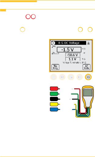
4.At the beginning of each chapter there will be a wiring diagram showing the test lead hook-up. The screen will also show the test lead hook-up.
RED Ring (B) 1
GRN Ground
BLK Tip (A) 1
YEL Ring (B) 2
BLU Tip (A) 2
5
Introduction |
3M™ Dynatel™ Advanced Modular System 965AMS |
Getting Started
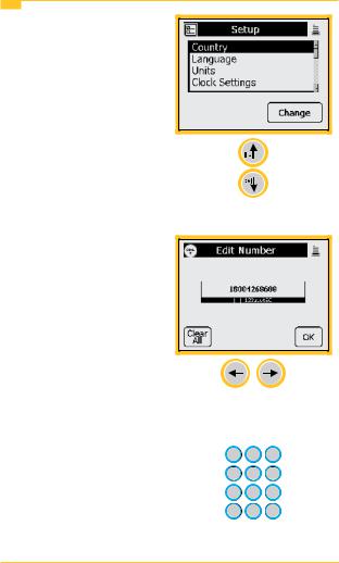
5. Some screens require you to choose from a list of possible choices.
Use the up and down arrow keys to make your choice.
6. Other screens may allow you to enter information such as telephone numbers.
You can position the cursor by using the Left and Right arrow keys.
7. This symbol indicates you should use the blue keys to enter numeric values or numbers.
6
3M™ Dynatel™ Advanced Modular System 965AMS |
Introduction |
Getting Started
8.Use the 
 (escape) key to quit the current screen without making any changes. Use multiple escapes to return to the Welcome screen.
9.The battery symbol in the upper right-hand corner of the display gives an indication of the approximate battery capacity. Each bar represents one-quarter of the full capacity.
10.The unit is powered by a rechargeable NiMH battery pack. The unit will also work with the “AA” battery pack. Six “AA” batteries are required. Dispose of the batteries per your company procedures. See Care & Maintenance for more information on using the rechargeable battery pack.
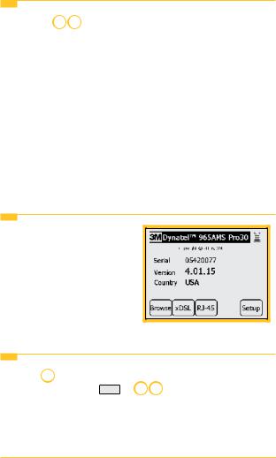
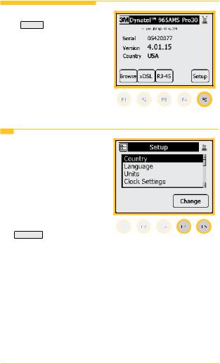
Welcome Screen
This is the screen that you see  when you first turn on the tester.
It shows the model name, serial number, software version, and selected country.
Help
Press the  key at any time in any screen to get help with the current function. Press OK or
 to return to the previous screen.
7
Introduction |
3M™ Dynatel™ Advanced Modular System 965AMS |
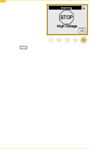
High Voltage
This screen indicates a high voltage (120 VAC/VDC or greater) has been detected between the test leads when not in the Voltage Mode. The tester has opened an internal relay
to protect itself from damage. Use standard safety practices for disconnecting the test leads since high voltage may be present. Press OK to restart the 965AMS tester.
8
3M™ Dynatel™ Advanced Modular System 965AMS |
System Setup |
System Setup
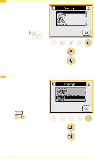
Start with the Welcome Screen. Press Setup to review the global settings or to make changes.
Country
1. Use the Country setup to  configure the tester for a specific country. Selecting a new country will configure the tester with the setups
for language, units, clock format, wire gauges,
and cable types for that particular country. Press
Change to make changes or to review the current settings.
9
System Setup |
3M™ Dynatel™ Advanced Modular System 965AMS |
Country
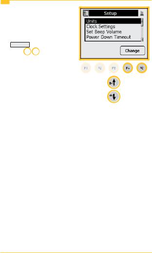
2.Use the up and down arrow keys to highlight a country. You will be warned about changing country-specific default values and asked to confirm or cancel your selection. Press OK to
continue or press 
 to quit without making changes.
Language
1.Use the Language setup to change only the language in the tester. Countryspecific default values are not affected. Use the up and down arrow keys to highlight a new language.
Press OK |
to continue or |
press |
to quit without |
making changes.
10
3M™ Dynatel™ Advanced Modular System 965AMS |
System Setup |
Module
1.Use the Module setup to select the type of module that is installed in your tester. The module type is listed on the label on the module.
Use the up and down arrow keys to highlight Module. Press Change to make changes or to review the current settings.
Network Setup
1.Use Network Setup to change network options used to connect to computers or ADSL circuits.
Use the up and down arrow keys to highlight Network Setup. Press Change to make changes or to review the current settings.
11
System Setup |
3M™ Dynatel™ Advanced Modular System 965AMS |
Units
1.Use the Units menu to change the Units of Measure. Use the up
and down arrow keys to highlight Units. Press
Change to continue or press 
 to quit without making changes.
12
3M™ Dynatel™ Advanced Modular System 965AMS |
System Setup |
Units
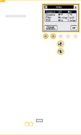
2.Use the up and down arrow keys to select the units
you want to change. Press  to change the units of measure. An “X” in a box indicates your choice.
Distance: Feet or Meters: This affects all distances displayed in the 965AMS
tester.
Degrees: Fahrenheit or Centigrade: This affects all
temperatures used in the 965AMS tester.
Filter: C-Message or CCITT: This affects the filter used in the POTS Noise function. Use the C-Message filter in the US and Canada. Use the CCITT (also called “Psophometric”) filter in all other countries.
The 965AMS tester features a dBrnPfilter for noise tests in New Zealand. To set the default noise filter to dBrnP, set Filter option to CCITT. This filter is used only in units sold in New Zealand; for all other countries, the CCITT option uses a dBrnOp filter. Noise test results will be displayed as dBrnP.
TDR: Vp (Velocity Propagation) or m/µS (meters per microsecond): This affects the TDR “velocity of
propagation.” Use “Vp” in the US and Canada. Use “m/µS” in other countries. Press OK to accept any changes and return. Use the 
 key to return to the Welcome Screen without making changes.
13

System Setup |
3M™ Dynatel™ Advanced Modular System 965AMS |
User Info
1.Select User Info to add your Tech ID and job number to be added to saved test results.
Use the up and down arrow keys to highlight User Info. Press Change to make changes or to review the current settings.
2.Use the blue keys to enter your ID, name, etc. Press
 to highlight the Job Num field.
Use the blue keys to enter a job number or ID. Press OK to continue or press

 to quit without making changes.
14
3M™ Dynatel™ Advanced Modular System 965AMS |
System Setup |
Clock Settings
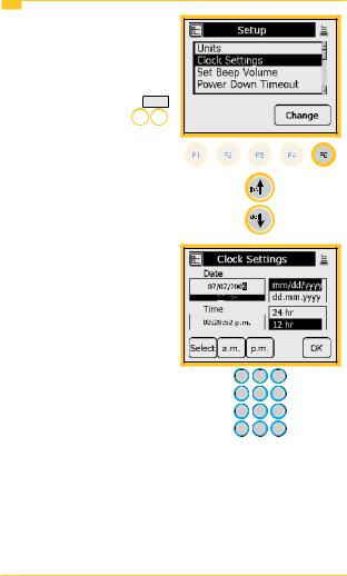
1.Use the Clock Settings menu to select the clock format and to set the correct time. Use the up
and down arrow keys to highlight Units. Press OK to continue or press 
 to quit without making changes.
2.Use the blue keys to enter the correct date.
15
System Setup |
3M™ Dynatel™ Advanced Modular System 965AMS |
Clock Settings
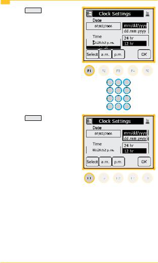
3.Press Select , then enter the correct time using the blue keys.
4.Press Select to enter the date format. Choose month, day, year or day, month, year.
16
3M™ Dynatel™ Advanced Modular System 965AMS |
System Setup |
Clock Settings
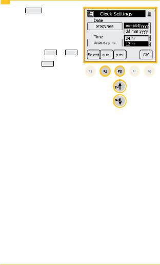
5.Press Select to choose the 12-hour or 24-hour format. Use the up and down arrow keys to select the format.
If you choose the 12-hour format, press a.m. or p.m. .
Note: Press OK at any time that you have completed your updates.
17
System Setup |
3M™ Dynatel™ Advanced Modular System 965AMS |
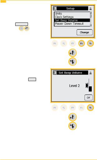
Set Beep Volume
1.Use this menu to change the 
Set Beep Volume. Use the up and down arrow keys to highlight Set Beep Volume.
Press Change |
to continue |
or press |
to quit |
without making changes.
2.Use the up and down arrow keys to change the beep volume. Press OK to save this volume setting.
18
3M™ Dynatel™ Advanced Modular System 965AMS |
System Setup |
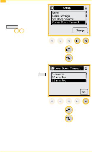
Power Down Timeout
1.Use this menu to change the Power Down Timeout. Use the up and down arrow keys to highlight Power Down Timeout. Press
Change to continue or press 
 to quit without making changes.
2.Use the up and down arrow keys to select the timeout
you want to use. Press OK to save your choice.
19
System Setup
Custom Cable
3M™ Dynatel™ Advanced Modular System 965AMS
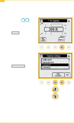
Use Custom Cable 1 or Custom Cable 2 to create a special cable you are using on a regular basis that has capacitance values that are different from existing cables. You can also access this function in the Opens Setup menu.
1.Press the blue 

 key to enter the Opens measurement function.
2.Press Setup to enter the Setup menu.
3.Use the up and down arrow keys to select Custom 1 or Custom 2.
Press Edit Custom .
20
3M™ Dynatel™ Advanced Modular System 965AMS |
|
System Setup |
|||
Custom Cable |
|
|
|
|
|
|
|
|
|
|
|
4. Use the blue keys to enter |
|
|
|
|
|
|
|
|
|
||
|
the capacitance to ground. |
|
|
|
|
|
Press Select Mutual . |
|
|
|
|
|
|
|
|
|
|
|
|
|
|
|
|
5. Use the blue keys to enter the mutual capacitance.
Press Select Ohms .
21

System Setup |
3M™ Dynatel™ Advanced Modular System 965AMS |
||||
Custom Cable |
|
|
|
|
|
|
|
|
|
|
|
6. Use the blue keys to enter |
|
|
|
|
|
|
|
|
|
||
|
ohms per thousand feet. |
|
|
|
|
|
Press Select Velocity . |
|
|
|
|
|
|
|
|
|
|
|
|
|
|
|
|
7. Use the blue keys to enter the velocity propagation. If you do not know this value, use 0.68.
Press Select Cable .
22

3M™ Dynatel™ Advanced Modular System 965AMS |
System Setup |
Custom Cable
8.Use the up and down arrow keys to select Custom 1 or Custom 2.
Press OK to save the custom cable.
23
System Setup |
3M™ Dynatel™ Advanced Modular System 965AMS |
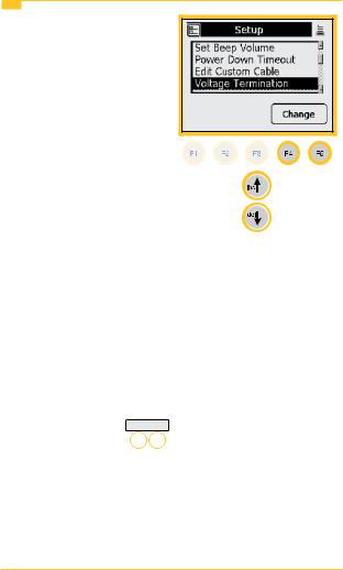
Voltage Termination
1. The Voltage Termination option allows you to select the input impedance of the 965AMS digital voltmeter (in supported countries only). The input impedance of the internal 965AMS voltmeter is normally 1Mohm. However, some legacy systems use voltage measurement systems
with input impedances of 100Kohms. This option is provided to maintain
measurement compatibility with those systems.
If 100Kohm termination is selected, the 965AMS tester will display ‘100K’ on the voltage measurement.
Use this menu to change the Voltage Termination. Use the up and down arrow keys to highlight Voltage Termination. Press Change to continue or press 

to quit without making changes.
24

3M™ Dynatel™ Advanced Modular System 965AMS |
System Setup |
Voltage Termination
2.Use the up and down arrow keys to select the Voltage Termination you want to
use. Press OK to save your choice.
25

Measurement Functions |
3M™ Dynatel™ Advanced Modular System 965AMS |
Measurement Functions
The 12 measurement functions include:
 DC and AC voltage measurements
 milliAmps and ground resistance measurements
 Ohms measurement and Soak Test
Self-Calibrate, Stored Results and Ohms-to-Distance Calculator

 Opens distance measurement

 Send Tones
Resistance Fault Locate: Distance measurement to a resistive fault
DSL Loss and Noise plus the Spectrum Analyzer and Resistance Balance

 Time Domain Reflectrometer (TDR)
POTS Loss, Noise, Longitudenal Balance, Load Coil Counter and Caller ID
 Automatic testing of circuits using “Expert Pair Tests”
 Talk Set
26
3M™ Dynatel™ Advanced Modular System 965AMS |
Measurement Functions |
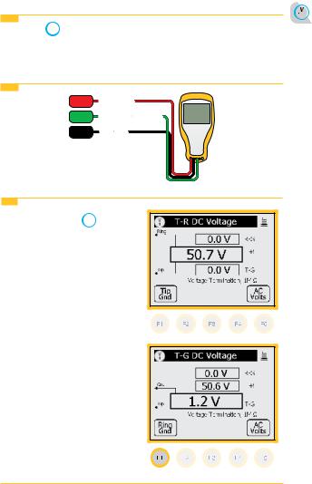
Volts-DC or AC
The Volts  function measures the DC voltage or AC voltage between Tip, Ring and Ground.
Volts-DC or AC>Hook-Up
RED |
Ring (B) |
GRN |
Ground (Earth) |
BLK |
Tip (A) |
Volts-DC or AC>Operation
1.Press the blue  key to start the voltage measurement function.
2.This screen displays the T-R voltage in the larger active measurement box.
3. Press to display the T-G voltage. The T-R measurement will be saved on the screen in a smaller box until a new measurement updates the screen.
27

Measurement Functions |
3M™ Dynatel™ Advanced Modular System 965AMS |
Volts-DC or AC>Operation
4. Press  to display the R-G voltage. The T-G measurement will be saved on the screen in a smaller box until a new measurement updates the screen.
5. All measurements are erased when you exit this function.
Volts-DC or AC>AC Volts
1. Press AC Volts to measure AC volts.
AC Normal Range—Active Line:
1.R-G and T-G should have the same AC voltage. If they are not equal the pair will probably have noise.
2.T-R should be 0 volts
Note: Maximum voltage = 300 volts DC, 250 volts AC
28
3M™ Dynatel™ Advanced Modular System 965AMS |
Measurement Functions |
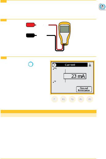
Loop Current
Loop Current  measures the loop current in an active line.
Loop Current>Hook-Up
RED Ring (A)
BLK Tip (B)
Loop Current>Operation
1.Press the blue  key to start this test.
2.This is a continuous measurement until you disconnect the test leads or choose another function.
Normal Measurements
|
OK |
Marginal |
Not OK |
Current |
>23mA |
20-23mA |
<20mA |
29
Measurement Functions |
3M™ Dynatel™ Advanced Modular System 965AMS |
Loop Current>Operation
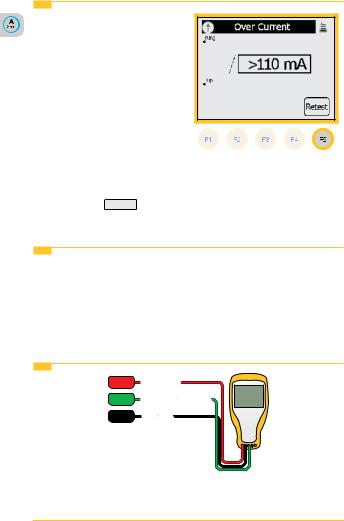
3. Over Current Warning
The tester has detected a current greater than 110 mA.
Over current can damage the test set. Use standard
safety practices for disconnecting the test leads and eliminating the source
of the over current.
Disconnect all test leads then press Retest to continue.
Loop Current>Ground Resistance
The Ground Resistance function compares the customer protector ground resistance to an active central office pair.
Note: The Ground Resistance function only works with central offices with the Tip connected to ground.
Loop Current>Ground Resistance>Hook-Up
RED |
Ring (B) |
GRN |
Ground (Earth) |
BLK |
Tip (A) |
30
 Loading...