


DynatelTM 965DSP-B
Subscriber Loop Analyzer
Instruction Manual
October, 1997
78-8097-6012-3 Rev A
1
2

Welcome to the Instruction Manual for the 965DSP-B. ‘DSP’ means ‘Digital Signal Processor.’ Digital Signal Processing allows the 965DSP-B instrument to provide the fast and flexible test functions needed for diagnostic testing. ‘B’ means ‘Basic’. The ‘B’ version does not have the TDR function found in the 965DSP.
This document will give you a brief overview of the product, a description of the test functions, and some technical hints on how to find common problems on telecommunications cables.
This document is not meant to be a substitute for diagnostic test training. For further information on complete training, contact 3M Telecom Systems Technical Service at: 800 426 8688.
Table of Contents: |
|
Out of the Box |
4 |
Screen |
5 |
Keypad |
5 |
Control keys |
6 |
Editing |
6 |
Function keys |
7 |
Functions: |
|
Contrast |
9 |
High Voltage |
9 |
Voltage |
10 |
Current |
11 |
Resistance |
12 |
Toolbox |
13 |
Self Calibrate |
14 |
Load Coils |
15 |
Ohms/Distance |
16 |
Caller ID |
17 |
Opens |
18 |
Tone |
21 |
RFL |
23 |
ISDN |
29 |
dB |
31 |
Auto |
34 |
Talk Set |
37 |
Care and Maintenance |
39 |
Specification |
42 |
Warranty Information |
43 |
3
Out of Box
Here’s what you will find when you unpack the shipping box:
965DSP-B
Carrying Case
NMH Battery Pack
(inside the 965DSP-B)
Spare Battery Holder
Test Leads
-Red/Black Pair
-Blue/Yellow Pair
-Green Lead Shorting Strap AC/DC Adaptor Power Cord Instruction Manual Quick Card Warranty Card
The 965DSP-B comes in the carrying case and should remain in the case to give extra protection from shock and the environment.
The 965DSP-B comes with the battery pack already installed. You may need to charge the battery before using the unit. Please see page 39 for information on charging the battery pack.
The Spare Battery Holder holds six “AA” alkaline batteries, and should only be used if the battery pack is discharged and the AC/DC converter is not available.
The 965DSP-B comes with 5 test leads. Red, Black and Green are used for most functions. Yellow is used for RFL. The Shorting Strap is only used in RFL.
The AC/DC adaptor will convert 110 or 220 Vac into the 12 Vdc used for charging the 965DSP- B. A North American 110 Vac Power Cord is provided.
Additional information is also found in the 965DSP-B help screens. For Technical Service, Warranty or Repair questions call: 800 426 8688 or contact your Local 3M Representative.
© Minnesota Mining and Manufacturing
3M Telecom Systems Division
6801 River Place Blvd.
Austin, Texas 78726-9000 USA
4
Screen
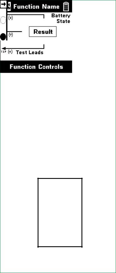
The 965DSP-B screen is a graphical LCD (Liquid Crystal Display) that gives high resolution for viewing text and graphics. The screen format is similar to the following for most functions.
Test Leads
Test Lead icons are shown on each measurement screen. They always point to the color dots on the front label that corresponds to the real test leads.
Keypad
The 965DSP-B Keypad has twelve yellow and red “Control Keys” and twelve blue “Function Keys”.
5

Control Keys
Use the red and yellow keys to control the actions and the setup of the 965DSP-B and its functions. The active control keys for each function are shown at the bottom of the corresponding screen.
Use the [Back] key to return to a previous step in a function.
Use the [Contrast] key to adjust the contrast or to turn the backlight on or off.
The [Save] key is reserved for future software enhancements, and is a ‘dash’ or ‘minus’ sign when editing numbers.
Use the [On/Off] key to turn the 965DSP on or off.
Use the [Tab] key to select between different options.
Use the [Setup] key to change the setup of any function.
Use the [Help] key to get help with any screen.
Use the [Enter] key to accept changes or move to the next step in a function.
Use the [Up] and [Down] keys to scroll to different menu options.
Use the [Left] and [Right] keys to move between different options.
Editing
Use the following keys when editing numbers:
Use  to insert a space to the left of the cursor.
Use  to delete the number above the cursor.
Use  to add a ‘dash’ in a telephone number or a minus sign for levels or temperature.
6

Function Keys
Use the blue keys to select the different test functions in the 965DSP-B. The blue keys become number keys when editing.
Use the [Voltage] key to measure DC or AC voltage.
Use the [Current] key to measure loop or ground Current.
Use the [Resistance] key to measure resistance.
Use the [Toolbox] key to access: Load Coil Count, Self-Calibration, Ohms to Distance, or Caller ID.
Use the [Opens] key to find the distance to an ‘open’ (or break) in a pair or cable.
Use the [Tone] key to send tones for pair identification or measuring loss.
Use the [RFL] key to find the distance to a resistance fault on a pair.
Use the [ISDN] key to verify the presence of an ISDN signal, and to measure near-end and far-end errors on an active ISDN line.
The [TDR] key is not used in the 965DSP-B. Contact 3M Customer Sevice at 800 426 8688 concerning TDR upgrades.
Use the [dB] key to measure Loss, Noise, Longitudinal Balance, or Wideband Loss.
Use the [Auto] key to perform a series of tests on an Active or Inactive pair.
Use the [Talk Set] key to dial numbers or to place a phone call on a working pair.
All functions (except for Tone and TDR) ‘time out’ in five minutes if no key has been pressed. Tone and TDR time out after 30 minutes.
7
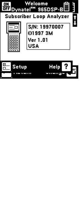
Welcome Screen
This is the screen you see when you first turn on the 965DSP-B. It shows the model name, serial number, copyright date, software version, and the version country.
When the Welcome screen shows, press [Setup] to go to the Setup screen.
Setup
Press [Enter] to change the Units of Measurements (Distance and Temperature).
Press [Back] to return to the Welcome screen.
8
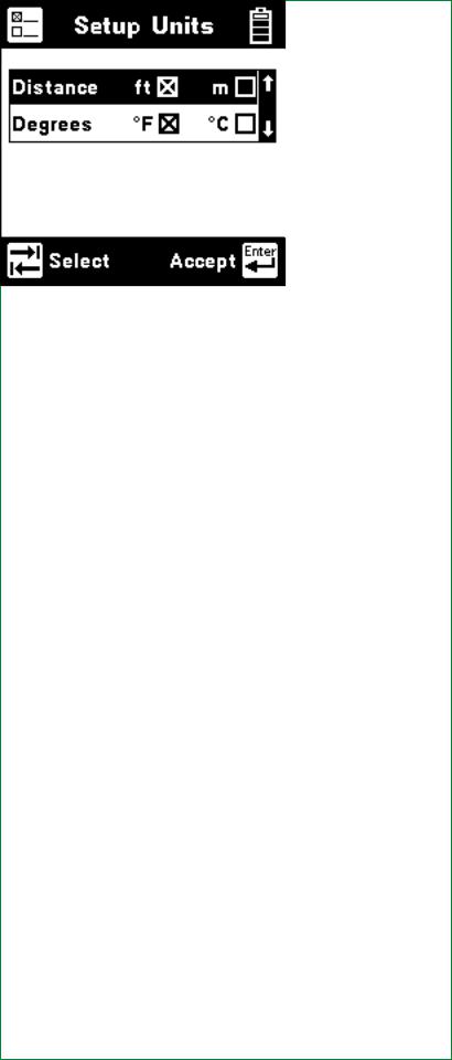
Units
Use the [Up] and [Down] keys to highlight either Distance or Degrees. Use the [Tab] key to select the units of measurement.
Use [Enter] to accept the changes and return. Use [Back] to return without making changes.
Contrast
Press the [Contrast] key to display the contrast screen. Use the [Up] and [Down] arrow keys to adjust the contrast. Press the [Contrast] key again to turn the backlight on or off.
9
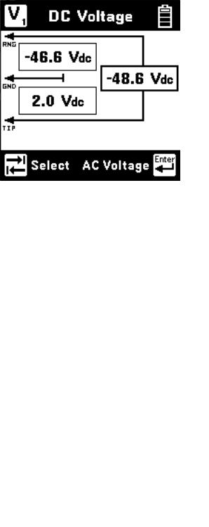
Voltage
This function first measures and displays the DC voltage between the Red and Black test leads.
Press the [Tab] key to move to the next test lead configuration.
Press the [Enter] key to switch between DC and AC voltage.
Press the [Tab] key to move to the next test lead configuration.
Press the [Enter] key to switch between AC and DC voltage.
10
Current
This function measures the current flowing into the Red and Black test leads (and a 430 Ohm resistor inside the 965DSP-B). Connect the Red and Black leads to the pair to measure loop current. Connect the Red lead to the voltage side of the pair and the Black lead to ground to measure ground current.
If the Current is greater than 110 mA , you will see the following ‘Current Warning’ screen:
This screen indicates that a high current has been detected between the test leads and that the 965DSP-B has opened an internal relay to protect itself from damage. Use standard safety practices for disconnecting the test leads. Press the [Enter] key to start the Current test again.
11
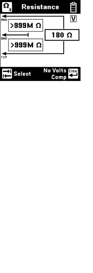
Resistance
This function first measures the resistance between the Red and Black test leads.
Press the [Tab] key to move to the next test lead configuration.
The “V” in the upper right corner of the screen indicates that the resistance measurement compensates for C.O. voltage on the line.
Press the [Enter] key to remove the voltage compensation. Use this test only if you have first determined there is no DC voltage on the pair (by using the Voltage function). The noncompensated measurement is slightly faster, but is not as accurate if there is voltage on the line.
12
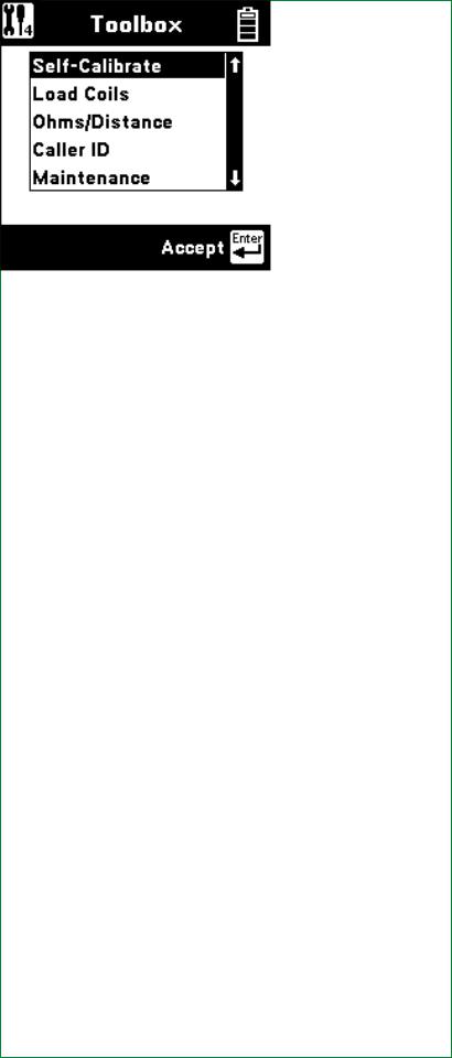
Toolbox
Use the [Up] and [Down] arrow key to move to the desired ‘tool’, then press the [Enter] key to accept the choice.
The Toolbox contains four additional functions:
•Self-Calibrate
•Load Coils
•Ohms to Distance
•Caller ID
Descriptions of these functions are found in the following pages.
The fifth item in the menu (Maintenance) is only used during 965DSP-B factory service.
13
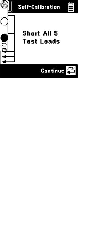
Self-Calibration
Use this function to calibrate the 965DSP-B anytime the outside temperature changes by more than 35°F (20°C). Calibrate the 965DSP-B at the same temperature at which it will be used.
You will see the following screen as soon as you select Self-Calibration from the Toolbox. Test lead connections (open or shorted) are not important during this phase of the calibration.
Short all five leads when prompted, then press [Enter] to continue.
The screen shows “Self-Calibration Complete” when the calibration is done.
14
 Loading...