


3B SCIENTIFIC® PHYSICS
Leistungs-Funktionsgenerator U8533510
Bedienungsanleitung
01/08 SP/ALF
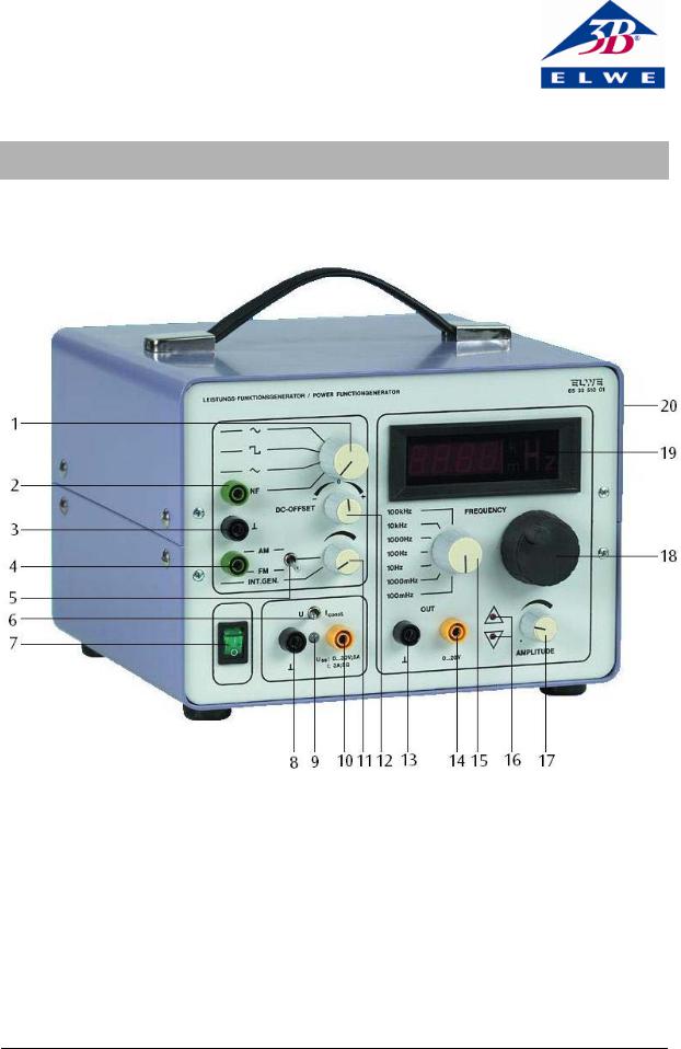
1 |
Wahlschalter für Kurvenform und Verstärkereingang |
12 |
Offset-Einsteller mit Schalter |
2 |
Verstärkereingang |
13 |
Massebuchse des Generators |
3 |
Massebuchse |
14 |
Ausgang des Generators |
4 |
Eingangsbuchse für AM/FM Steuerspannung |
15 |
Frequenzbereichssteller |
5 |
Kippschalter für AMbzw. FM-Modulation |
16 |
LED zur Begrenzungsanzeige |
6 |
Kippschalter für Betriebsart des Leistungsverstärkers |
17 |
Amplitudenregler für Generator und Leistungsverstär- |
7 |
Netzschalter |
|
ker |
8 |
Massebuchse für Leistungsverstärker |
18 |
Frequenzfeineinsteller |
9 |
LED Betriebsanzeige des Leistungsverstärkers |
19 |
LED-Anzeige |
10 |
Ausgang des Leistungsverstärkers |
20 |
Rückseite BNC-Buchse (TTL-Pegel der Generatorfre- |
11 |
Abschwächer für AM/FM mit Schalter |
|
quenz) |
1

1. Sicherheitshinweise
Das Gerät entspricht den Sicherheitsbestimmungen für elektrische Mess-, Steuer-, Regelund Laborgeräte nach DIN EN 61010 Teil 1 und ist nach Schutzklasse I aufgebaut. Es ist für den Betrieb in trockenen Räumen vorgesehen, die für elektrische Betriebsmittel geeignet sind.
Bei bestimmungsgemäßem Gebrauch ist der sichere Betrieb des Gerätes gewährleistet. Die Sicherheit ist jedoch nicht garantiert, wenn das Gerät unsachgemäß bedient oder unachtsam behandelt wird.
Wenn anzunehmen ist, dass ein gefahrloser Betrieb nicht mehr möglich ist, ist das Gerät unverzüglich außer Betrieb zu setzen (z.B. bei sichtbaren Schäden) und gegen unbeabsichtigten Betrieb zu sichern.
In Schulen und Ausbildungseinrichtungen ist der Betrieb des Gerätes durch geschultes Personal verantwortlich zu überwachen.
•Vor Erstinbetriebnahme überprüfen, ob der auf der Gehäuse-Rückseite aufgedruckte Wert für die Netzanschlussspannung den örtlichen Anforderungen entspricht.
•Vor Inbetriebnahme das Gehäuse und die Netzleitung auf Beschädigungen untersuchen und bei Funktionsstörungen oder sichtbaren Schäden das Gerät außer Betrieb setzen und gegen unbeabsichtigten Betrieb sichern.
•Gerät nur an Steckdosen mit geerdetem Schutzleiter anschließen.
•Experimentierleitungen vor dem Anschluss auf schadhafte Isolation und blanke Drähte überprüfen.
•Lüftungsschlitze am Gehäuse immer frei lassen, um ausreichende Luftzirkulation zur Kühlung der inneren Bauteile zu gewährleisten.
•Gerät nur durch eine Elektrofachkraft öffnen lassen.
2. Beschreibung
Der Leistungs-Funktionsgenerator ist zur Durchführung von Experimenten in den Themenbereichen Schwingungslehre, Akustik, Ultraschall und magnetische Induktion geeignet, wobei das Hauptaugenmerk auf den niedrigen Frequenzbereichen liegt. Die Frequenz ist in sieben Dekaden von 10 mHz bis 100 kHz einstellbar.
Das Gerät ist ein extern AM und FM (Sweep) modulierbarer Funktionsgenerator mit Leistungsverstärker und digitaler Frequenzanzeige für Wert und Einheit. Das Gerät ist wahlweise als Funktionsgenerator, Gleichspannungsquelle oder Leistungsverstärker in der Betriebsart Spannungsbzw. Stromquelle mit einer Leistung von 50 Watt verwendar. Eine Übersteuerung der Verstärker durch Offset-Spannung oder zu großem Eingangssignal wird angezeigt. Die Ausgänge sind durch elektronische Schutzschaltungen gegen Überlast geschützt.
Der Funktionsgenerator U8533510-115 ist für eine Netzspannung von 115 V (±10 %) ausgelegt, U8533510-230 für 230 V (±10 %).
3. Technische Daten
Signalform: |
Sinus, Rechteck, Dreieck |
|||
Frequenzbereich: |
<10 mHz…>100 kHz in |
|||
|
|
7 Dekaden |
|
|
Messausgang: |
0 - 20 V, 10 mA |
|||
FM-Modulation: |
0 - 5 V Steuerspannung |
|||
|
|
bewirkt Frequenzvariation |
||
|
|
1:1000 |
|
|
|
|
|
|
|
Bereich |
|
0 V |
|
5 V |
|
|
|
|
|
100 mHz oder |
|
ca. 10 mHz |
|
1 Hz |
1000 mHz |
|
|
||
|
|
|
|
|
10 Hz oder 100 |
|
ca 100 mHz |
|
100 Hz |
Hz |
|
|
||
|
|
|
|
|
1 kHz oder |
|
ca 10 Hz |
|
10 kHz |
10 kHz |
|
|
||
|
|
|
|
|
100 kHz |
|
ca. 100 Hz |
|
100 kHz |
|
|
|
|
|
AM-Modulation: |
0 - 5 V Steuerspannung |
|||
|
|
bewirkt Ausgangsamplitu- |
||
|
|
de 0 - 100% |
|
|
Anzeige: |
3½-stellig LED |
|
||
Ziffern: |
13-mm-LED, rot |
|||
Offset: |
±10 V |
|
||
Leistungsverstärker: |
bezogen auf Generator: 1,5 |
|||
|
|
bezogen auf NF-Buchse: 10 |
||
Begrenzungsanzeige: |
bei Übersteuerung NF- |
|||
|
|
Signal oder Offset |
||
Leistung: |
50 W |
|
||
Spannungsquelle: |
0 - 30 V, Imax = 5 A |
|||
Stromquelle: |
2,1 A an 6 Ω |
|
||
Betriebsspannung: |
siehe Geräterückseite |
|||
Abmessungen: |
ca. 125 x 170 x 225 mm3 |
|||
Masse: |
ca. 6,5 kg |
|
||
4.Bedienung
4.1Generatorbetrieb
•Netzspannung mittels Netzschalter (7) einschalten.
•Signalform mit Wahlschalter (1) wählen.
•Offsetschalter (12) und Abschwächer (11) in Raststellung.
•Frequenz mittels Steller (15 und 18) einstellen.
•Mit Drehsteller (17) Amplitude einstellen.
•Mittels Kippschalter (6) die Betriebsart, Strom oder Spannung, für die Leistungsverstärkung wählen.
Ausgangssignal des Leistungsverstärkers immer auf Buchse (8) beziehen!
2

•Ggf. Offset einstellen.
•Bei AM-Modulation den Kippschalter (5) in die Stellung AM bringen.
•An der Buchse (4) Steuerspannung 0 - 5 V anlegen und mit dem Abschwächer (11) Hub einstellen.
•Bei FM-Modulation den Kippschalter (5) in die Stellung FM bringen.
•An der Buchse (4) Steuerspannung 0 - 5 V anlegen und mit dem Abschwächer (11) Frequenzvariation einstellen.
4.2 Leistungsverstärker mit externem Signal
•An die Buchse NF (2) Signal von 0 - 1 V anlegen.
•Wahlschalter (1) in die Stellung NF bringen.
•Mittels Drehsteller (17) Amplitude einstellen.
Bei größeren Eingangssignalen wird durch die Leuchtdioden (16) die "Übersteuerung" angezeigt.
4.3Leistungsverstärker als Gleichspannungsoder Gleichstromquelle
•Drehsteller (17) auf Linksanschlag drehen.
•Abschwächer (11) auf INT.GEN. stellen (Klickgeräusch). Wahlschalter (1) darf nicht auf NF stehen.
•Mittels Einsteller für Offset (12) und für Amplitude (17) gewünschte Ausgangsspannung bzw. –strom einstellen.
Zusätzliche Hinweise
In der Betriebsart "Spannungsquelle" entspricht der zeitliche Verlauf bzw. die Form der Ausgangsspannung bis zu einem maximalen Strom von 5 A, dem Verlauf bzw. der Form der Eingangsspannung.
In der Betriebsart "Stromquelle" entspricht dagegen der zeitliche Verlauf bzw. die Form des Ausgangstromes bis zu einem maximalen Widerstandswert der Last von 6 Ω dem Verlauf bzw der Form der Eingangsspanung.
Elwe Didactic GmbH • Steinfelsstr. 6 • 08248 Klingenthal • Deutschland • www.elwedidactic.com 3B Scientific GmbH • Rudorffweg 8 • 21031 Hamburg • Deutschland • www.3bscientific.com Technische Änderungen vorbehalten
© Copyright 2008 3B Scientific GmbH
3B SCIENTIFIC® PHYSICS
Power Function Generator U8533510
Instruction sheet
01/08 SP/ALF
1 |
Selector switch for waveforms and amplifier input |
14 |
Generator output |
2 |
Amplifier input |
15 |
Frequency range selector |
3 |
Ground socket |
16 |
LED indicator for limiting |
4 |
Input socket for AM/FM control voltage |
17 |
Amplitude regulator for generator |
5 |
Toggle switch for AMor FM-modulation |
|
and power amp |
6 |
Toggle switch for power amplifier operating mode |
18 |
Frequency fine adjustment knob |
7 |
Mains switch |
19 |
LED-display |
8 |
Ground socket for power amplifier |
20 |
BNC-on reverse (TTL level for |
9 |
LED mode indicator for power amplifier |
|
generated frequency) |
10Power amplifier output
11Attenuator for AM/FM with switch
12Offset-trimmer for switch
13Ground socket for generator
1

1. Safety instructions
The device conforms to the safety regulations for electrical measuring, control, monitoring and laboratory equipment, as specified under DIN EN 61010, section 1, and is designed to be classified as protection class I equipment. It is intended for operation in a dry environment as this is suitable for the operation of electrical equipment and systems.
Safe operation of the equipment is guaranteed, provided it is used correctly. However, there is no guarantee of safety if the equipment is used in an improper or careless manner.
If it is deemed that the equipment can no longer be operated without risk (e.g. visible damage has occurred), the equipment should be switched off immediately and secured against any unintended use.
In schools and other educational institutions, the operation of the function generator must be supervised by qualified personnel.
•Before putting the function generator into operation, confirm that the specifications printed on the rear side of the housing are compatible with the local mains voltage.
•Before putting the function generator into operation, check the housing for any damage. In the event of any malfunction/operational defect or visible damage, switch off the unit immediately and secure it from unintentional use.
•The instrument may only be connected to the mains via a socket that has an earth connection.
•Before making any connections, check the experiment leads for damaged insulation and exposed wires.
•Never cover the air vents and heat sink at the rear of the housing. These are necessary in order to ensure sufficient circulation of air required for cooling the components inside the equipment.
•The equipment may only be opened/repaired by qualified and trained personnel.
2. Description
This high-power function generator is intended for conducting experiments on the topics of harmonic oscillation, acoustics, ultrasonics and magnetic induction, concentrating mainly on the lowfrequency range. Frequency can be adjusted over seven decades ranging from 10 mHz to 100 kHz.
The equipment involves an external AM and FM (sweep) modulating function generator with power amplification and digital frequency display showing values and units. It can be used as a function generator, DC voltage source or power amplifier and provides alternative operating modes such that it
can be used as a voltage or a current source with a power output of 50 watts. Any overload of the amplifier due to the setting of the offset voltage or excessive input voltage is shown on the display. The outputs are protected against overloading by electronic protection circuitry.
Function generator U8533510-115 is designed for a mains voltage of 115 V (±10 %) while U8533510-230 operates with 230 V (±10 %).
3. Technical data
Signal form: |
|
Sine, square, triangle |
|||
Frequency range: |
|
<10 mHz…>100 kHz |
|||
in |
|
|
|
|
|
|
|
|
7 decades |
|
|
Measuring output: |
|
0 - 20 V, 10 mA |
|||
FM modulation: |
|
0 - 5 V control voltage |
|||
|
|
|
effecting a frequency |
||
|
|
|
variation in the ratio |
||
|
|
|
1:1000 |
|
|
|
|
|
|
|
|
Range |
|
|
0 V |
|
5 V |
|
|
|
|
|
|
100 mHz or |
|
10 mHz approx. |
|
1 Hz |
|
1000 mHz |
|
|
|||
|
|
|
|
|
|
10 Hz or 100 |
|
100 mHz approx. |
|
100 Hz |
|
Hz |
|
|
|||
|
|
|
|
|
|
1 kHz or |
|
10 Hz approx. |
|
10 kHz |
|
10 kHz |
|
|
|||
|
|
|
|
|
|
100 kHz |
|
100 Hz approx. |
|
100 kHz |
|
|
|
|
|
|
|
AM modulation: |
|
0 - 5 V control voltage |
|||
|
|
|
effecting a change in |
||
|
|
|
output amplitude in |
||
|
|
|
the range 0 - 100% |
||
Display: |
|
3½-digit LED |
|
||
Numerals: |
|
13-mm LED, red |
|||
Offset: |
|
±10 V |
|
||
Power amplifier gain: |
Referenced to |
||||
|
|
|
generator: 1.5x |
||
|
|
|
Referenced to |
||
|
|
|
LF (NF)-socket: 10x |
||
Limit display: |
|
On overload of LF sig- |
|||
|
|
|
nal or offset |
|
|
Power output: |
|
50 W |
|
||
Voltage source: |
|
0 - 30 V, Imax = 5 A |
|||
Current source: |
|
2.1 A at 6 Ω |
|
||
Operating voltage: |
|
See reverse of device |
|||
Dimensions: |
|
125 x 170 x 225 mm |
|||
|
|
|
approx. |
|
|
Weight: |
|
6.5 kg approx. |
|||
2

4.Operation
4.1Generator mode
•Turn on the mains via the mains switch (7).
•Select the waveform using the selector (1).
•Set the offset switch (12) and attenuator (11) to the ratcheted setting.
•Set frequency using controls (15 and 18).
•Set amplitude using rotary knob (17).
•Use toggle (6) to select current or voltage source operating mode for power amplification. The output signal from the power amp should always be referenced to socket (8).
•Set offset if required.
•For AM modulation set toggle (5) to AM setting.
•Apply 0 - 5 V control voltage to socket (4) and set the amplitude limits using the attenuator (11).
•For FM modulation set toggle (5) to FM setting.
•Apply 0 - 5 V control voltage to socket (4) and set the frequency limits using the attenuator (11).
4.2 Power amp with external signal
•Apply a 0 - 1 V signal to LF (NF) socket (2)
•Set the selector (1) to LF (NF).
•Use rotary knob (17) to set amplitude.
For excessively large input signals LED (16) will indicate an "Overload".
4.3 Power amp as voltage or current source
•Turn knob (17) fully to the left.
•Set attenuator (11) to INT.GEN. (it will click). Selector (1) must not be set to LF (NF).
•Use the offset trimmer (12) and amplitude knob (17) to set the output voltage or current.
4.4 Miscellaneous
In "voltage source" mode, the timing or wave form of the voltage output matches the input voltage for currents up to 5 A.
In "Current source" mode, the timing or waveform of the voltage output matches the input voltage up to a maximum load resistance of 6 Ω.
The NF socket stands for low frequency (LF)
Elwe Didactic GmbH • Steinfelsstr. 6 • 08248 Klingenthal • Germany • www.elwedidactic.com 3B Scientific GmbH • Rudorffweg 8 • 21031 Hamburg • Germany • www.3bscientific.com Subject to technical amendments
© Copyright 2008 3B Scientific GmbH
 Loading...