


 Loading...
Nokia Customer Care
Service Manual
RH-99; RH-100; RH-105; RH-106 (Nokia 1200;
Nokia 1208)
Mobile Terminal
Part No: 9200070 (Issue 2)
COMPANY CONFIDENTIAL
Copyright © 2007 Nokia. All rights reserved.

|
|
|
RH-99; RH-100; RH-105; RH-106 |
|
|
|
Amendment Record Sheet |
Amendment Record Sheet |
|
|
|
|
|
|
|
Amendment No |
Date |
Inserted By |
Comments |
Issue 1 |
05/2007 |
Y Liu |
|
|
|
|
|
Issue 2 |
11/2007 |
Y Liu |
Service Tools updated |
|
|
|
|
Page ii |
COMPANY CONFIDENTIAL |
Issue 2 |
|
Copyright © 2007 Nokia. All rights reserved. |
|

RH-99; RH-100; RH-105; RH-106
Copyright
Copyright
Copyright © 2007 Nokia. All rights reserved.
Reproduction, transfer, distribution or storage of part or all of the contents in this document in any form without the prior written permission of Nokia is prohibited.
Nokia, Nokia Connecting People, and Nokia X and Y are trademarks or registered trademarks of Nokia Corporation. Other product and company names mentioned herein may be trademarks or tradenames of their respective owners.
Nokia operates a policy of continuous development. Nokia reserves the right to make changes and improvements to any of the products described in this document without prior notice.
Under no circumstances shall Nokia be responsible for any loss of data or income or any special, incidental, consequential or indirect damages howsoever caused.
The contents of this document are provided "as is". Except as required by applicable law, no warranties of any kind, either express or implied, including, but not limited to, the implied warranties of merchantability and fitness for a particular purpose, are made in relation to the accuracy, reliability or contents of this document. Nokia reserves the right to revise this document or withdraw it at any time without prior notice.
The availability of particular products may vary by region.
IMPORTANT
This document is intended for use by qualified service personnel only.
Issue 2 |
COMPANY CONFIDENTIAL |
Page iii |
|
Copyright © 2007 Nokia. All rights reserved. |
|

RH-99; RH-100; RH-105; RH-106
Warnings and cautions
Warnings and cautions
Warnings
•IF THE DEVICE CAN BE INSTALLED IN A VEHICLE, CARE MUST BE TAKEN ON INSTALLATION IN VEHICLES FITTED WITH ELECTRONIC ENGINE MANAGEMENT SYSTEMS AND ANTI-SKID BRAKING SYSTEMS. UNDER CERTAIN FAULT CONDITIONS, EMITTED RF ENERGY CAN AFFECT THEIR OPERATION. IF NECESSARY, CONSULT THE VEHICLE DEALER/ MANUFACTURER TO DETERMINE THE IMMUNITY OF VEHICLE ELECTRONIC SYSTEMS TO RF ENERGY.
•THE PRODUCT MUST NOT BE OPERATED IN AREAS LIKELY TO CONTAIN POTENTIALLY EXPLOSIVE ATMOSPHERES, FOR EXAMPLE, PETROL STATIONS (SERVICE STATIONS), BLASTING AREAS ETC.
•OPERATION OF ANY RADIO TRANSMITTING EQUIPMENT, INCLUDING CELLULAR TELEPHONES, MAY INTERFERE WITH THE FUNCTIONALITY OF INADEQUATELY PROTECTED MEDICAL DEVICES. CONSULT A PHYSICIAN OR THE MANUFACTURER OF THE MEDICAL DEVICE IF YOU HAVE ANY QUESTIONS. OTHER ELECTRONIC EQUIPMENT MAY ALSO BE SUBJECT TO INTERFERENCE.
•BEFORE MAKING ANY TEST CONNECTIONS, MAKE SURE YOU HAVE SWITCHED OFF ALL EQUIPMENT.
Cautions
•Servicing and alignment must be undertaken by qualified personnel only.
•Ensure all work is carried out at an anti-static workstation and that an anti-static wrist strap is worn.
•Ensure solder, wire, or foreign matter does not enter the telephone as damage may result.
•Use only approved components as specified in the parts list.
•Ensure all components, modules, screws and insulators are correctly re-fitted after servicing and alignment.
•Ensure all cables and wires are repositioned correctly.
•Never test a mobile phone WCDMA transmitter with full Tx power, if there is no possibility to perform the measurements in a good performance RF-shielded room. Even low power WCDMA transmitters may disturb nearby WCDMA networks and cause problems to 3G cellular phone communication in a wide area.
•During testing never activate the GSM or WCDMA transmitter without a proper antenna load, otherwise GSM or WCDMA PA may be damaged.
Page iv |
COMPANY CONFIDENTIAL |
Issue 2 |
|
Copyright © 2007 Nokia. All rights reserved. |
|

RH-99; RH-100; RH-105; RH-106
For your safety
For your safety
QUALIFIED SERVICE
Only qualified personnel may install or repair phone equipment.
ACCESSORIES AND BATTERIES
Use only approved accessories and batteries. Do not connect incompatible products.
CONNECTING TO OTHER DEVICES
When connecting to any other device, read its user’s guide for detailed safety instructions. Do not connect incompatible products.
Issue 2 |
COMPANY CONFIDENTIAL |
Page v |
|
Copyright © 2007 Nokia. All rights reserved. |
|

RH-99; RH-100; RH-105; RH-106
Care and maintenance
Care and maintenance
This product is of superior design and craftsmanship and should be treated with care. The suggestions below will help you to fulfil any warranty obligations and to enjoy this product for many years.
•Keep the phone and all its parts and accessories out of the reach of small children.
•Keep the phone dry. Precipitation, humidity and all types of liquids or moisture can contain minerals that will corrode electronic circuits.
•Do not use or store the phone in dusty, dirty areas. Its moving parts can be damaged.
•Do not store the phone in hot areas. High temperatures can shorten the life of electronic devices, damage batteries, and warp or melt certain plastics.
•Do not store the phone in cold areas. When it warms up (to its normal temperature), moisture can form inside, which may damage electronic circuit boards.
•Do not drop, knock or shake the phone. Rough handling can break internal circuit boards.
•Do not use harsh chemicals, cleaning solvents, or strong detergents to clean the phone.
•Do not paint the phone. Paint can clog the moving parts and prevent proper operation.
•Use only the supplied or an approved replacement antenna. Unauthorised antennas, modifications or attachments could damage the phone and may violate regulations governing radio devices.
All of the above suggestions apply equally to the product, battery, charger or any accessory.
Page vi |
COMPANY CONFIDENTIAL |
Issue 2 |
|
Copyright © 2007 Nokia. All rights reserved. |
|

RH-99; RH-100; RH-105; RH-106
ESD protection
ESD protection
Nokia requires that service points have sufficient ESD protection (against static electricity) when servicing the phone.
Any product of which the covers are removed must be handled with ESD protection. The SIM card can be replaced without ESD protection if the product is otherwise ready for use.
To replace the covers ESD protection must be applied.
All electronic parts of the product are susceptible to ESD. Resistors, too, can be damaged by static electricity discharge.
All ESD sensitive parts must be packed in metallized protective bags during shipping and handling outside any ESD Protected Area (EPA).
Every repair action involving opening the product or handling the product components must be done under ESD protection.
ESD protected spare part packages MUST NOT be opened/closed out of an ESD Protected Area.
For more information and local requirements about ESD protection and ESD Protected Area, contact your local Nokia After Market Services representative.
Issue 2 |
COMPANY CONFIDENTIAL |
Page vii |
|
Copyright © 2007 Nokia. All rights reserved. |
|

RH-99; RH-100; RH-105; RH-106
Battery information
Battery information
Note: A new battery's full performance is achieved only after two or three complete charge and discharge cycles!
The battery can be charged and discharged hundreds of times but it will eventually wear out. When the operating time (talk-time and standby time) is noticeably shorter than normal, it is time to buy a new battery.
Use only batteries approved by the phone manufacturer and recharge the battery only with the chargers approved by the manufacturer. Unplug the charger when not in use. Do not leave the battery connected to a charger for longer than a week, since overcharging may shorten its lifetime. If left unused a fully charged battery will discharge itself over time.
Temperature extremes can affect the ability of your battery to charge.
For good operation times with Ni-Cd/NiMh batteries, discharge the battery from time to time by leaving the product switched on until it turns itself off (or by using the battery discharge facility of any approved accessory available for the product). Do not attempt to discharge the battery by any other means.
Use the battery only for its intended purpose. Never use any charger or battery which is damaged.
Do not short-circuit the battery. Accidental short-circuiting can occur when a metallic object (coin, clip or pen) causes direct connection of the + and - terminals of the battery (metal strips on the battery) for example when you carry a spare battery in your pocket or purse. Short-circuiting the terminals may damage the battery or the connecting object.
Leaving the battery in hot or cold places, such as in a closed car in summer or winter conditions, will reduce the capacity and lifetime of the battery. Always try to keep the battery between 15°C and 25°C (59°F and 77° F). A phone with a hot or cold battery may temporarily not work, even when the battery is fully charged.
Batteries' performance is particularly limited in temperatures well below freezing. Do not dispose of batteries in a fire!
Dispose of batteries according to local regulations (e.g. recycling). Do not dispose as household waste.
Page viii |
COMPANY CONFIDENTIAL |
Issue 2 |
|
Copyright © 2007 Nokia. All rights reserved. |
|

RH-99; RH-100; RH-105; RH-106
Company Policy
Company Policy
Our policy is of continuous development; details of all technical modifications will be included with service bulletins.
While every endeavour has been made to ensure the accuracy of this document, some errors may exist. If any errors are found by the reader, NOKIA MOBILE PHONES Business Group should be notified in writing/e- mail.
Please state:
•Title of the Document + Issue Number/Date of publication
•Latest Amendment Number (if applicable)
•Page(s) and/or Figure(s) in error
Please send to:
NOKIA CORPORATION
Nokia Mobile Phones Business Group
Nokia Customer Care
PO Box 86
FIN-24101 SALO
Finland
E-mail: Service.Manuals@nokia.com
Issue 2 |
COMPANY CONFIDENTIAL |
Page ix |
|
Copyright © 2007 Nokia. All rights reserved. |
|

RH-99; RH-100; RH-105; RH-106
Company Policy
(This page left intentionally blank.)
Page x |
COMPANY CONFIDENTIAL |
Issue 2 |
|
Copyright © 2007 Nokia. All rights reserved. |
|
RH-99; RH-100; RH-105; RH-106
Nokia 1200; Nokia 1208 Service Manual Structure
Nokia 1200; Nokia 1208 Service Manual Structure
1 General information
2 Service Tools
3 FPC's Disassembly and reassembly instructions
4 Baseband troubleshooting
5 RF troubleshooting
6 System module Glossary
Issue 2 |
COMPANY CONFIDENTIAL |
Page xi |
|
Copyright © 2007 Nokia. All rights reserved. |
|

RH-99; RH-100; RH-105; RH-106
Nokia 1200; Nokia 1208 Service Manual Structure
(This page left intentionally blank.)
Page xii |
COMPANY CONFIDENTIAL |
Issue 2 |
|
Copyright © 2007 Nokia. All rights reserved. |
|
Nokia Customer Care
1 — General information
Issue 2 |
COMPANY CONFIDENTIAL |
Page 1 –1 |
|
Copyright © 2007 Nokia. All rights reserved. |
|

RH-99; RH-100; RH-105; RH-106
General information
(This page left intentionally blank.)
Page 1 –2 |
COMPANY CONFIDENTIAL |
Issue 2 |
|
Copyright © 2007 Nokia. All rights reserved. |
|

RH-99; RH-100; RH-105; RH-106
General information
Table of Contents |
|
Product selection.................................................................................................................................................... |
1–5 |
Display and keypad features ................................................................................................................................. |
1–5 |
Features................................................................................................................................................................... |
1–5 |
Hardware features ............................................................................................................................................ |
1–5 |
Software features.............................................................................................................................................. |
1–6 |
UI features.......................................................................................................................................................... |
1–6 |
Mobile enhancements....................................................................................................................................... |
1–7 |
Technical specifications......................................................................................................................................... |
1–8 |
General specifications....................................................................................................................................... |
1–8 |
Battery endurance............................................................................................................................................. |
1–8 |
Environmental conditions ................................................................................................................................ |
1–8 |
Electrical characteristics ................................................................................................................................... |
1–9 |
List of Tables |
|
Table 1 Power ......................................................................................................................................................... |
1–7 |
Table 2 Car............................................................................................................................................................... |
1–7 |
Table 3 Audio .......................................................................................................................................................... |
1–7 |
Table 4 Normal and extreme voltages ................................................................................................................. |
1–9 |
Table 5 Current consumption............................................................................................................................. |
1–10 |
List of Figures |
|
Figure 1 The product picture of RH-99/100 and RH-105/106 ............................................................................ |
1–5 |
Issue 2 |
COMPANY CONFIDENTIAL |
Page 1 –3 |
|
Copyright © 2007 Nokia. All rights reserved. |
|

RH-99; RH-100; RH-105; RH-106
General information
(This page left intentionally blank.)
Page 1 –4 |
COMPANY CONFIDENTIAL |
Issue 2 |
|
Copyright © 2007 Nokia. All rights reserved. |
|
RH-99; RH-100; RH-105; RH-106
General information
Product selection
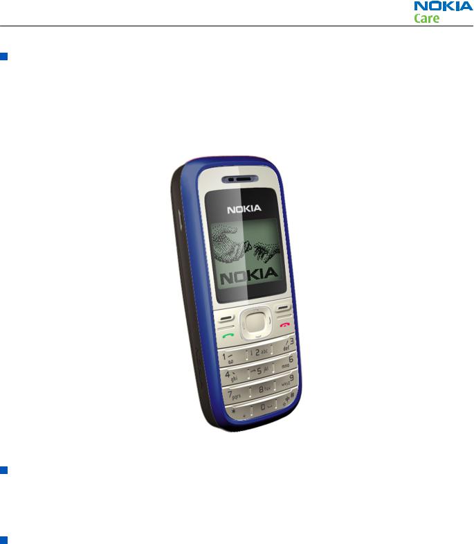
The RH-99/105 is the EU version of the telephone with a dual band transceiver unit designed for the GSM900 and GSM1800 networks.
The RH-100/106 is the US version of the telephone with a dual band transceiver unit designed for the GSM850 and GSM1900 networks.
The RH-105/106 has color display.
Figure 1 The product picture of RH-99/100 and RH-105/106
Display and keypad features
•High resolution B&W display (96x68 pixels)
•4UI-style, 4-way navigation key including selection key
•Rubber keymat
Features
Hardware features
•GSM E900/1800 (EU/APAC version)
•GSM 850/1900 (US version)
•Gefion Engine, UPP Costo, 4 layer PWB
•7-11 earpiece +13mm speaker audio solution
•AMR/HR/FR(US version not included)/EFR codecs
•Internal antenna
Issue 2 |
COMPANY CONFIDENTIAL |
Page 1 –5 |
|
Copyright © 2007 Nokia. All rights reserved. |
|

RH-99; RH-100; RH-105; RH-106
General information
•Charger plug
•System connector: Easy flash II
•Headset connector
•Internal vibrator
•User changeable frontand back covers
•SIM (1.8 and 3.0 V)
Software features
•OS: CUI
•UI Style: Jack 4
•Phone sharing (Multi-phonebook and call duration record)
•MP3-grade ringing tones and 32 polyphonic ringing tones.
•Flash light
•Analog clock
UI features
Messaging |
• |
SMS messaging |
|
• |
Predictive text input |
|
• Asia-Pacific: English, Chinese Simplified, Chinese Traditional, Thai, |
|
|
|
Philipino, Vietnamese, Bahasa Indonesia, Bahasa Malaysia, Hindi |
|
• Europe and Africa: Danish, Dutch, English, French, Finnish, German, |
|
|
|
Icelandic, Italian, Portugese, Spanish, Swedish, Norwegian, Turkish, Greek, |
|
|
Bulgarian, Ukranian, Hebrew, Arabic, Slovakian, Czech, Hungarian, Polish, |
|
|
Romanian, Serbian, Croatian, Slovenian, Russian, Estonian, Latvian, |
|
|
Lithuanian |
|
• Non-predictive text input: Farsi, Zulu, Xhosa, Sesotho, Swahili, Merathi, |
|
|
|
Tamil, Gujarati, Bengali |
|
|
|
Memory functions |
• |
Phone book (up to 200 entries in internal phone memory; up to 250 entries |
|
|
on simcard.) |
|
|
|
Connectivity |
• |
Plug and play connector |
|
|
|
Call management |
• |
Speed dialing: up to 8 names (keys 2-9) |
|
• Last number redial from dialed calls list (dial key brings out the dialed calls |
|
|
|
list) |
|
• Automatic redial (max 10 attempts) |
|
|
• Automatic answer (works with headset or car kit only) |
|
|
• Call waiting, call hold, call divert, and call timer |
|
|
• Automatic and manual network selection |
|
|
• |
Vibrating alert |
|
|
|
Voice features |
• |
Integrated handsfree speaker |
|
|
|
Page 1 –6 |
COMPANY CONFIDENTIAL |
Issue 2 |
|
Copyright © 2007 Nokia. All rights reserved. |
|

RH-99; RH-100; RH-105; RH-106
General information
Personalise |
• Graphics, icons, animations, logos |
|
• 3 games available . The selection of games depends on the region the phone |
|
is sold in (Snake, Dice, Rapid Rolls, Pocket Carrom.) |
|
• Ringing tones: Polyphonic tones and MP3 grade sound ringingtones. |
|
|
Phone features |
• Phone Features |
|
• Demo application accessible both with and without SIM mode. |
|
• Speaking clock & speaking alarm |
|
• Prepaid tracker (network dependent service) |
|
|
Mobile enhancements
Mobile enhancements for RH-99/100 and RH-105/106
|
|
Table 1 Power |
|
|
|
Type |
Name |
|
BL-5C |
Battery 1020 mAh Li-Ion |
|
|
|
|
BL-5CA |
Battery 700 mAh Li-Ion (included in sales pack) |
|
|
|
|
AC-3 |
Light charger |
|
|
|
|
AC-4 |
Light charger |
|
|
|
|
AC-5 |
Light charger |
|
|
|
|
DC-4 |
Mobile charger |
|
|
|
|
HH-12 |
Holder Easy Mount |
|
|
|
|
DT-14 |
Battery charger desk stand |
|
|
|
|
CA-44 |
Charger Adapter |
|
|
|
|
|
|
Table 2 Car |
|
|
|
Type |
Name |
|
CK-20W |
Multimedia car kit |
|
|
|
|
CR-39 |
Nokia universal holder |
|
|
|
|
|
|
Table 3 Audio |
|
|
|
Type |
|
Name |
HS-40 |
|
Headset |
|
|
|
HS-47 |
|
Stereo Headset |
|
|
|
HS-60 |
|
Fashion Headset |
|
|
|
HDA-11 |
|
TTY Adapter |
|
|
|
Issue 2 |
COMPANY CONFIDENTIAL |
Page 1 –7 |
|
Copyright © 2007 Nokia. All rights reserved. |
|

|
|
|
|
RH-99; RH-100; RH-105; RH-106 |
|
|
|
|
|
|
General information |
|
Technical specifications |
|
|
|
|
|
|
|
|
||
|
|
|
|
||
General specifications |
|
|
|
|
|
|
|
|
|
|
|
|
Unit |
Dimension (mm) |
Weight (g) |
|
Volume (cc) |
Transceiver with Li-Ion |
104x43x17 |
80 |
|
70 |
|
battery pack |
|
|
|
|
|
|
|
|
|
|
|
Battery endurance |
|
|
|
|
|
|
|
|
|
|
|
|
Talk time |
|
|
|
|
Battery: BL-5C 1020 mAh |
|
Up to 300 min |
|
|
|
|
|
|
|
|
|
Battery: BL-5CA 700 mAh |
|
Up to 300 min |
|
|
|
|
|
|
|
|
|
|
|
|
|
|
|
|
Standby time |
|
|
|
|
Battery: BL-5C 1020 mAh |
|
Up to 380 hours |
|
|
|
|
|
|
|
|
|
Battery: BL-5CA 700 mAh |
|
Up to 380 hours |
|
|
|
|
|
|
|
|
|
Note: Variation in operation times will occur depending on SIM card, network settings and usage. Talk time is increased by up to 30% if half rate is active and reduced by 5% if enhanced full rate is active.
Environmental conditions
Environmental |
Ambient temperature |
Notes |
condition |
|
|
Normal operation |
-15 oC ... +55 oC |
Specifications fulfilled |
Reduced performance |
-30 ...15 oC and +55oC ... +70 oC |
Operational only for short periods |
Intermittent or no |
-40 oC ... -30 oC and +70 oC ... +85oC |
Operation not guaranteed but an |
operation |
|
attempt to operate will not damage |
|
|
the phone |
|
|
|
No operation or |
<-40 oC and >+85 oC |
No storage. An attempt to operate |
storage |
|
may cause permanent damage |
|
|
|
Charging allowed |
-15 oC ... +55 oC |
|
Long term storage |
0 oC ... +85 oC |
|
conditions |
|
|
|
|
|
Page 1 –8 |
COMPANY CONFIDENTIAL |
Issue 2 |
|
Copyright © 2007 Nokia. All rights reserved. |
|
RH-99; RH-100; RH-105; RH-106
General information
Environmental |
Ambient temperature |
Notes |
condition |
|
|
Humidity and water |
|
Relative humidity range is 5 to 95%. |
resistance |
|
Condensed or dripping water may |
|
|
|
|
|
cause intermittent malfunctions. |
|
|
Protection against dripping water |
|
|
has to be implemented in (enclosure) |
|
|
mechanics. |
|
|
Continuous dampness will cause |
|
|
permanent damage to the module. |
|
|
|
Electrical characteristics
Table 4 Normal and extreme voltages
Voltage |
|
|
Voltage (V) |
Condition |
|
|
|
General conditions |
|
|
|
|
||
Nominal voltage |
3.90V |
a |
||
|
|
|
||
Lower extreme voltage |
3.30V |
b |
||
|
|
|
||
Higher extreme voltage |
4.30V |
c |
||
|
|
|
|
|
|
|
|
HW shutdown voltages |
|
|
|
|
|
|
|
|
|
||
Vmstr+ |
2.1V ± 0,1V |
Off to on |
||
|
|
|
||
Vmstr- |
1.9V ± 0,1V |
On to off |
||
|
|
|
|
|
|
|
|
SW shutdown voltages |
|
|
|
|
|
|
|
|
|
|
|
SW shutdown |
3. |
1V |
|
In call |
|
|
|
|
|
SW shutdown |
3. |
2V |
|
In idle |
|
|
|
|
|
|
|
|
Min operating voltage |
|
|
|
|
|
|
|
|
|
|
|
Vcoff+ |
3. |
1V |
± 0,1V |
Off to on |
|
|
|
|
|
Vcoff- |
2. |
8V |
± 0,1V |
On to off |
|
|
|
|
|
|
|
|
HW reset demands |
|
|
|
|
|
|
|
|
|
|
|
Min |
1. |
0V |
|
d |
|
|
|
|
|
Max |
-- |
|
|
|
|
|
|
|
|
a.The nominal voltage is defined as being 15% higher than the lower extreme voltage. TA will test with this nominal voltage at an 85% range (0.85x3.9V a 3.3V).
b.This limit is set to be above SW shutdown limit in TA.
c.During fast charging of an empty battery, this voltage might exceed this value. Voltages between 4.20 and 4.60 might appear for a short while.
d.The minimum battery cell voltage required for the reset circuitry to turn on. This is not confirmed by measures at pt.
Issue 2 |
COMPANY CONFIDENTIAL |
Page 1 –9 |
|
Copyright © 2007 Nokia. All rights reserved. |
|

RH-99; RH-100; RH-105; RH-106
General information
Table 5 Current consumption
Condition |
Min |
Typical |
Max |
Unit |
Call (MoU) |
|
. |
|
mA |
GSM 850 |
|
225 |
|
|
(E)GSM 900 |
|
208 |
|
|
GSM 1800 |
|
188 |
|
|
GSM 1900 |
|
168 |
|
|
|
|
|
|
|
Idle (MoU) |
|
2.0 |
|
mA |
|
|
|
|
|
Power off |
25 |
30 |
45 |
µA |
|
|
|
|
|
Page 1 –10 |
COMPANY CONFIDENTIAL |
Issue 2 |
|
Copyright © 2007 Nokia. All rights reserved. |
|
Nokia Customer Care
2 — Service Tools
Issue 2 |
COMPANY CONFIDENTIAL |
Page 2 –1 |
|
Copyright © 2007 Nokia. All rights reserved. |
|

RH-99; RH-100; RH-105; RH-106
Service Tools
(This page left intentionally blank.)
Page 2 –2 |
COMPANY CONFIDENTIAL |
Issue 2 |
|
Copyright © 2007 Nokia. All rights reserved. |
|

RH-99; RH-100; RH-105; RH-106
Service Tools
|
Table of Contents |
|
Service tools............................................................................................................................................................ |
|
2–5 |
ACF-8 ................................................................................................................................................................... |
|
2–5 |
AXS-4................................................................................................................................................................... |
|
2–5 |
CA-106DS ............................................................................................................................................................ |
|
2–5 |
CA-10DS .............................................................................................................................................................. |
|
2–5 |
CA-111DS ............................................................................................................................................................ |
|
2–6 |
CA-112DS ............................................................................................................................................................ |
|
2–6 |
CA-28DS .............................................................................................................................................................. |
|
2–6 |
CA-31D ................................................................................................................................................................ |
|
2–6 |
CA-35S................................................................................................................................................................. |
|
2–7 |
CA-41PS............................................................................................................................................................... |
|
2–7 |
CA-5S ................................................................................................................................................................... |
|
2–7 |
DA-49 .................................................................................................................................................................. |
|
2–7 |
DAU-9S ................................................................................................................................................................ |
|
2–8 |
FLC-2 ................................................................................................................................................................... |
|
2–8 |
FLS-4S.................................................................................................................................................................. |
|
2–8 |
FLS-5 ................................................................................................................................................................... |
|
2–8 |
FPS-10................................................................................................................................................................. |
|
2–9 |
FPS-8 ................................................................................................................................................................... |
|
2–9 |
JBV-1 ................................................................................................................................................................ |
|
2–10 |
MJ-130.............................................................................................................................................................. |
|
2–10 |
PCS-1 ................................................................................................................................................................ |
|
2–10 |
PKD-1 ............................................................................................................................................................... |
|
2–11 |
RJ-164 .............................................................................................................................................................. |
|
2–11 |
SA-41................................................................................................................................................................ |
|
2–11 |
SF-10 ................................................................................................................................................................ |
|
2–11 |
SF-56 ................................................................................................................................................................ |
|
2–11 |
SPS-1 ................................................................................................................................................................ |
|
2–12 |
SRT-6................................................................................................................................................................ |
|
2–12 |
SS-54 ................................................................................................................................................................ |
|
2–12 |
ST-30................................................................................................................................................................ |
|
2–12 |
ST-32................................................................................................................................................................ |
|
2–13 |
SX-4.................................................................................................................................................................. |
|
2–13 |
XCS-4 ................................................................................................................................................................ |
|
2–13 |
XRS-6................................................................................................................................................................ |
|
2–13 |
Service software concept.................................................................................................................................... |
|
2–14 |
POS (Point of Sales) flash concept ................................................................................................................ |
|
2–14 |
POS flash concept with FLS-5 ........................................................................................................................ |
|
2–15 |
FPS-10 Prommer box flash concept.............................................................................................................. |
|
2–16 |
JBV-1 flash concept with FPS-10 ................................................................................................................... |
|
2–17 |
JBV-1 flash concept with FPS-8 ..................................................................................................................... |
|
2–18 |
Module jig (MJ-130) service concept............................................................................................................. |
|
2–19 |
List of Figures |
|
|
Figure 2 POS flash concept ................................................................................................................................. |
|
2–14 |
Figure 3 POS flash concept with FLS-5............................................................................................................... |
|
2–15 |
Figure 4 FPS-10 Prommer box flash concept.................................................................................................... |
2–16 |
|
Figure 5 JBV-1 flash concept with FPS-10 ......................................................................................................... |
|
2–17 |
Figure 6 JBV-1 flash concept with FPS-8............................................................................................................ |
|
2–18 |
|
|
|
Issue 2 |
COMPANY CONFIDENTIAL |
Page 2 –3 |
Copyright © 2007 Nokia. All rights reserved.

RH-99; RH-100; RH-105; RH-106
Service Tools
Figure 7 Module jig service concept .................................................................................................................. |
2–19 |
Page 2 –4 |
COMPANY CONFIDENTIAL |
Issue 2 |
|
Copyright © 2007 Nokia. All rights reserved. |
|

RH-99; RH-100; RH-105; RH-106
Service Tools
Service tools
The table below gives a short overview of service tools that can be used for testing, error analysis and repair of product RH-99; RH-100; RH-105; RH-106, refer to various concepts.
|
ACF-8 |
Universal power |
|
|
|
supply |
|
|
|
|
|
ACF-8 universal power supply is used to power FPS-8. ACF-8 has 6V DC and 2.1A output.
|
AXS-4 |
Service cable |
|
|
|
|
|
The AXS-4 D9-D9 service cable is used to connect two 9 pin D connectors for example between PC and FPS-8.
The cable length is 2 meters.
|
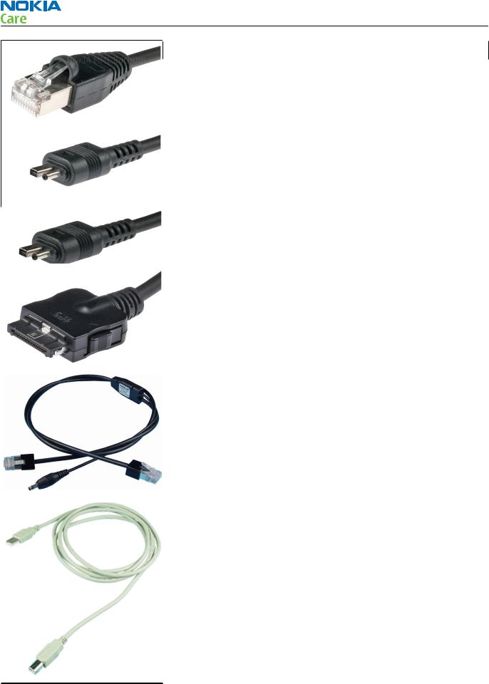
CA-106DS |
Easy flash II cable |
|
|
|
|
|
The cable is used for connecting phone DC port to the flash prommer
FPS-10.
|
CA-10DS |
Bi-directional |
|
|
|
Parallel Cable |
|
|
|
|
|
Bi-Directional parallel cable included in FPS-8 sales pack.
Issue 2 |
COMPANY CONFIDENTIAL |
Page 2 –5 |
|
Copyright © 2007 Nokia. All rights reserved. |
|
RH-99; RH-100; RH-105; RH-106
Service Tools
CA-111DS |
Easy flash II cable |
|
|
|
|
The cable is used for connecting phone DC port to either POS flashing device FLS-4S or to the PROMMER box FPS-11.
|
CA-112DS |
Easy flash II cable |
|
|
|
|
|
The CA-112DS easy flash II cable is used for connecting phone DC port to the PROMMER facilities (FLS-5, FPS-20).
|
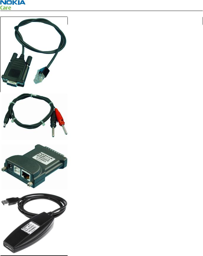
CA-28DS |
Service data cable |
|
|
|
|
|
The CA-28DS service cable is used to connect FLS-4S to the POS flash adapter for supplying a controlled operating voltage and data connection.
Note: Old XCS-1 cable can be used as well.
|
CA-31D |
USB cable |
|
|
|
|
|
The CA-31D USB cable is used to connect FPS-10 or FPS-11 to a PC. It is included in the FPS-10 and FPS-11 sales packages.
Page 2 –6 |
COMPANY CONFIDENTIAL |
Issue 2 |
|
Copyright © 2007 Nokia. All rights reserved. |
|

RH-99; RH-100; RH-105; RH-106
Service Tools
|
CA-35S |
Power cable |
|
|
|
|
|
CA-35S is a power cable for connecting, for example, the FPS-10 flash prommer to the Point-Of-Sales (POS) flash adapter.
|
CA-41PS |
Power cable |
|
|
|
|
|
Power cable for connection of e.g. the JBV-1 docking station to the
FPS-10 prommer box.
|
CA-5S |
DC cable |
|
|
|
|
|
The DC cable CA-5S is used to connect JBV-1 to the phone charger jack for ADC/VCHAR/ICHAR calibration
|
|
Note: Old SCB-3 can be used as well. |
||
|
|
|
|
|
|
DA-49 |
|
Docking station |
|
|
|
|
adapter |
|
|
|
|
|
|
The Docking Station adaptor is used for this phone in combination with JBV-1. The adapter supports flashing and energy management calibration.
Features include:
• compatible with the JBV-1
• easy phone attachment and detachment.
• reliable phone locking
• switch for detecting phone
• replaceable SIM interface
Issue 2 |
COMPANY CONFIDENTIAL |
Page 2 –7 |
|
Copyright © 2007 Nokia. All rights reserved. |
|
RH-99; RH-100; RH-105; RH-106
Service Tools
DAU-9S |
MBUS cable |
|
|
|
|
The MBUS cable DAU-9S has a modular connector and is used, for example, between the PC's serial port and module jigs, flash adapters or docking station adapters.
Note: Docking station adapters valid for DCT4 products.
|
FLC-2 |
DC cable |
|
|
|
|
|
FLC-2 is used with a flash adapter to supply a controlled operating voltage.
|
FLS-4S |
Flash device |
|
|
|
|
|
FLS-4S is a dongle and flash device incorporated into one package, developed specifically for POS use.
|
FLS-5 |
Flash device |
|
|
|
|
|
FLS-5 is a dongle and flash device incorporated into one package, developed specifically for POS use.
Note: FLS-5 can be used as an alternative to PKD-1.
Page 2 –8 |
COMPANY CONFIDENTIAL |
Issue 2 |
|
Copyright © 2007 Nokia. All rights reserved. |
|
Loading...