


Workshop manual |
510 16 77-26 |
|
|

Contents
Workshop manual
Jonsered CS 2240 and CS 2240S
Contents |
|
Index........................................................................ |
4 |
Introduction and safety instructions.................... |
6 |
Technical data...................................................... |
10 |
Service tools......................................................... |
12 |
Service data.......................................................... |
14 |
Safety equipment................................................. |
16 |
Repair instructions.............................................. |
24 |
Carburettor........................................................... |
33 |
Troubleshooting................................................... |
53 |
Jonsered has a policy of continuous product development and therefore reserves the right to modify the design and appearance of products without prior notice.
English – 3

Index
Index
B
Bar bolt 52
Replacing the bar bolt 52
C
Carburettor 33
Assemble on the saw 40
Assembly 38
Carburettor adjustment 41
Cleaning and inspection 37
Design 33
Dismantling 35
Function 34
Pressure testing the carburettor 39
Centrifugal clutch 30
Centrifugal clutch - refitting 31 Centrifugal clutch - removal 30 Inspection and cleaning 30
Chain brake 17
Chaine brake - reassembly 18 Cleaning and inspection 17 Dismantling the chaine brake 17
Chain catcher 20
Chain catcher - replacement 20
Crankcase and crankshaft 50
Crankshaft bearings - replacement 50 Crankshaft complete - dismantling 50 Crankshaft complete - reassembly 51
F
Fuel system 44
Replacing the fuel filter 44
Replacing the fuel hose/return hose 44 Replacing the air-purge 44
Venting the fuel tank 42
I
Ignition module and flywheel 28
Cleaning and inspection 28
Ignition module - testing 27
Ignition module and flywheel - refitting 29 Ignition module and flywheel - removal 28
Intake system 32
Air intake system removal 32 Assembling the intake system 32, 48 Cleaning and inspection 32
Introduction and safety instructions 7
Changes 7
General 7
General Instructions 8
Numbering 7
Safety 7
Special Instructions 8
Symbols in the Workshop Manual 9 Symbols on the saw 9
Structure 7 Target group 7 Tools 7
O
Oil pump and screen 31
Assembling the oil pump and screen 32 Cleaning and inspection 31 Dismantling the oil pump and screen 31
P
Piston and cylinder 45
Cleaning and inspection 45
Cylinder - pressure testing 49
Faults and causes 47
Piston and cylinder - refitting 47
Piston and cylinder - removal 45
S
Service data 14
Special tools 12
Silencer 19
Cleaning and inspection 19
Silencer - refitting 19
Silencer - removal 19
Starter 25, 26
Changing a broken or worn starter cord 26 Cleaning and inspection 25, 26 Replacing a worn recoil spring 27
Starter assembly - refitting 27
Starter assembly - removal 25
Tensioning the recoil spring 26
Start/Stop switch 20
Assembling the start/stop control 21 Cleaning and inspection 20 Dismantling the start/stop control 20
Stopping function 21
Stop switch - resistance measurement 21
T
Tank unit 42
Assembly 43
Dismantling 42
Technical Data 10
Threads 51
Repairing damaged threads 51
Throttle lock, throttle trigger
and return spring 22
Cleaning and inspection 23 Throttle lock, throttle trigger and return spring - refitting 23 Throttle lock, throttle trigger and return spring - removal 22
4 – English

Index
Trouble shooting 54
Trouble-shooting methods 55
V
Vibration damping system 43
Assembly 43
Cleaning and inspection 43
Dismantling 43
English – 5

Introduction and safety instructions
2 Introduction and safety instructions
Contents |
|
|
2.1 |
General ........................................................................................................................... |
7 |
2.2 |
Safety .............................................................................................................................. |
7 |
2.3 |
Target group .................................................................................................................... |
7 |
2.4 |
Changes........................................................................................................................... |
7 |
2.5 |
Tools ................................................................................................................................ |
7 |
2.6 |
Structure .......................................................................................................................... |
7 |
2.7 |
Numbering ....................................................................................................................... |
7 |
2.8 |
General instructions ........................................................................................................ |
8 |
2.9 |
Special instructions ......................................................................................................... |
8 |
2.10 |
Symbols on the saw ........................................................................................................ |
9 |
2.11 Symbols in the Workshop Manual ................................................................................... |
9 |
|
6 – English

Introduction and safety instructions
2 Introduction and safety instructions
2.1 General
This Workshop Manual describes in detail how the chain saw is to be fault traced, repaired and tested. A description of different safety measures that should be taken during repair work is also given.
2.2 Safety
Note! The section dealing with safety must be read and understood by all those carrying out repair work or service on the chain saw.
Warning symbols can be found in this Workshop Manual and on the chain saw. See “Symbols on the saw” and “Symbols in the Workshop Manual”. A new decal must be applied as soon as possible if a warning symbol on the chain saw has been damaged or is missing so that the greatest possible safety can be obtained when using the chain saw.
2.3 Target group
This Workshop Manual is written for personnel with general knowledge about the repair and service of chain saws.
The Workshop Manual must be read and understood by personnel who will carry out repair work and service on the chain saw. The Manual is also suitable for use when training new employees.
2.4 Changes
Modifications will be successively introduced on the chain saw during production. When these modifications affect the service and/or spare parts, separate service information will be sent out on each occasion. This means that in time this Workshop Manual will become out of date. In order to prevent this, the Manual should be read together with all service information concerning the chain saw in question.
2.5 Tools
Special tools are required for some stages. All service tools are listed in the Workshop Manual. Usage is evident from respective sections.
Always use Husqvarna’s original:
•Spare parts
•Service tools
•Accessories
2.6 Structure
This Workshop Manual can be used in two different ways:
•For the repair of a particular system on the chain saw.
•Dismantling and assembly of the entire chain saw.
Repair of a specific system
When a particular system on the chain saw is to be repaired, proceed as follows:
1.Look up the page for the system in question.
2.Carry out the sections: Dismantling
Cleaning and inspection
Assembling
Dismantling and assembling the entire chain saw
Proceed as follows when the entire chain saw is to be dismantled and assembled:
1.Look up the chapter “Repair instructions”, which deals with the Starter and carry out the instructions set out under Dismantling.
2.Work forward in the Manual and carry out Dismantling in the order set out in the sections.
3.Go back to the Starter and carry out the instructions under Cleaning and Inspection.
4.Work forward in the Manual and carry out
Cleaning and Inspection in the order set out in the sections.
5.Order or take out all requisite spare parts from the stores.
6.Look up the chapter “Repair instructions” which deals with the Crankcase and carry out the instructions set out under Assembling.
7.Work back in the Manual and carry out Assembling in the order set out in the sections.
Some sections include a Description of the actual unit in order to increase the basic understanding.
2.7 Numbering
Position references to components inside the figures are designated A, B, etc.
The figures are numbered 1, 2 etc.
The position references and figure numbers restart in each new section.
English – 7

Introduction and safety instructions
2.8 General instructions
The workshop where chain saw repairs are to be done must be equipped with safety equipment as set out in local provisions.
No one may repair the chain saw unless they have read and understood the content of this Workshop Manual.
In this workshop manual the following boxes indicate where caution should be taken.
WARNING!
The warning text warns of the risk of personal injury if the instructions are not followed.
NOTE!
The warning text warns of the risk of material damage if the instructions are not followed.
2.9 Special instructions
The fuel that is used in a chainsaw poses the following hazards:
•The fuel and its fumes are toxic.
•May cause irritation to skin or eyes.
•May cause breathing difficulties.
•Highly flammable.
When using compressed air the air jet should never be pointed at the body. Air can be forced into the bloodstream and cause fatal injury.
Wear ear protection when testing saws.
After testing a saw do not touch the silencer until it has cooled down. The silencer gets very hot and you may burn yourself. Wear protective gloves when working on the silencer.
The guide bar, chain and clutch cover (chain brake) must be fitted before the saw is started. If not, the clutch may come loose and cause injury.
Poor chain lubrication can result in failure of the chain, which could cause serious or fatal injury.
Take care to ensure that the spring inside the starter assembly does not fly out and cause injury. Wear eye protection. If the spring is under compression when the pulley is removed it could fly out and cause injury.
Before removing the tensioning spring from the chain brake, ensure that the brake is in the on position, otherwise the spring may fly out and cause injury.
After completing the repair the chain brake must be tested, see “Chain brake – reassembly \ Operating test”.
Always consider the fire risk. A chainsaw can produce sparks that could start a fire.
Inspect the chain catcher and replace it if it is damaged.
8 – English
Introduction and safety instructions
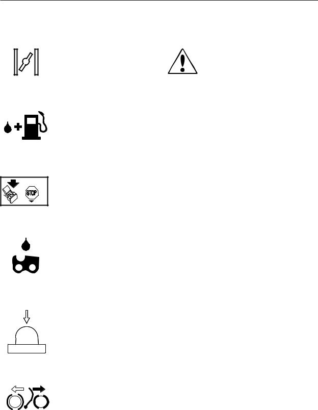
2.10 Symbols on the saw
The symbols below are embedded on the chain saw.
Choke Lever
Refuelling
Stop button
Filling with chain oil
Air purge
Chain brake, activated (right)
Chain brake, not activated (left)
2.11 Symbols in the Workshop Manual
This symbol warns of personal injury when the instructions are not followed
English – 9
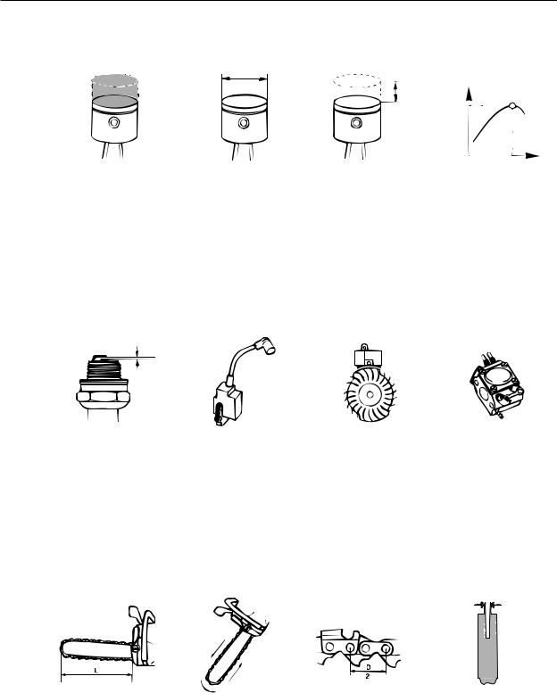
Technical data
3 Technical data
|
Displacement |
Cylinder bore |
Stroke |
Max power/speed |
|
cm3/cubic inches |
Ø mm/Ø inches |
mm/inches |
kW/hp/rpm |
CS 2240/S: |
40,9 / 2,49 |
41 / 1,51 |
31 / 1,22 |
1,8 / 2,4 / 9 000 |
Spark plug gap |
Ignition system |
Air gap |
Carburettor type |
mm/inches |
|
mm/inches |
|
CS 2240/S: 0,5 / 0,02 |
Walbro MBU-16 |
0,3 / 0,012 |
Zama EL41AC1T |
Effective cutting length |
Chain speed at |
Chain pitch |
Drive link |
cm/inches |
max power – revs |
mm/inches |
mm/inches |
|
m/s - r/min |
|
|
CS 2240/S: 33-46 / 13-18 |
17,3 / 9 000 |
8,25 / 0,325 |
1,3 / 0,050 - 1,5 / 0,058 |
10 – English
Technical data
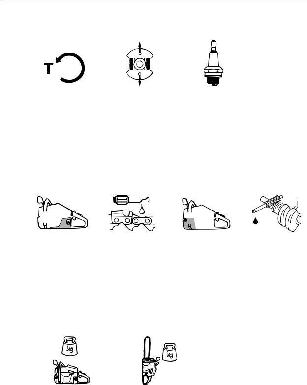
rpm
|
Idling speed |
Engagement speed |
Spark plug |
||
|
rpm |
|
|
rpm |
|
CS 2240/S: |
2 900 |
3 800 |
NGK BPMR 7A |
||
|
|
|
|
|
Champion RCJ 7Y |
|
|
|
|
|
|
|
|
|
|
|
|
|
GAS |
|
OIL |
|
|
|
|
|
|
|
Fuel tank capacity |
Oil pump capacity at |
Oil tank capacity |
Automatic oil pump |
|
Litres/US pints |
8,500 rpm, |
Litres/US pints |
|
|
|
ml/min |
|
|
CS 2240/S: |
0,37 / 0,78 |
9 |
0,25 / 0,53 |
Yes |
|
Weight without |
Weight with |
|
bar and chain |
bar and chain |
|
kg / lbs |
kg / lbs |
CS 2240/S: |
4,4 / 9,7 |
5,7 / 12,6 |
English – 11
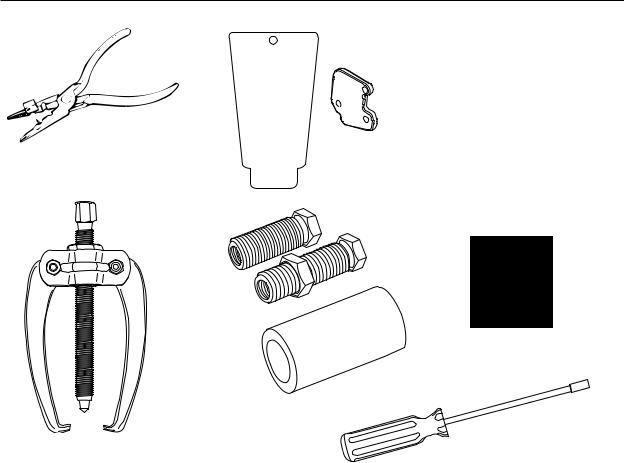
Special tools
4 Special tools
1 |
2 |
3 |
4 |
5 |
6 |
7 |
M5 |
M5 |
|
M6 |
8 |
9 |
10 |
11 |
12 – English
Special tools
12 |
13a |
13b |
|
|
15 |
16b |
16c |
|
||
|
|
17
16a
18
Item |
Description |
Used for |
Order no. |
1 |
Clutch tool |
Centrifugal clutch |
502 54 16-03 |
2 |
Piston stop |
Locking the crankshaft |
504 91 06-05 |
3 |
Fuel filter hook |
Withdrawing the fuel filter |
502 50 83-01 |
4 |
Allen key, 4mm |
For M5 bolts |
502 50 87-01 |
5 |
Allen key, 4mm |
For M5 bolts |
502 50 18-01 |
5 |
Allen key, 5mm |
For M6 bolts |
502 50 64-01 |
6 |
Pressure tester |
Pressure testing cylinder |
503 84 40-02 |
7 |
Feeler gauge |
Adjusting ignition module |
502 51 34-02 |
8 |
Assembly fixture |
Assembling chain saw |
502 51 02-01 |
9 |
Pressure gauge |
Pressurisation during testing |
531 03 06-23 |
10 |
Test spark plug |
Checking the ignition module |
501 97 64-01 |
11 |
Rev counter |
Adjusting carburettor |
502 71 14-01 |
12 |
Assembly pliers |
Fitting spark plug guard |
502 50 06-01 |
13a |
Cover plate, exhaust |
Sealing the exhaust port |
502 54 11-02 |
13b |
Cover plates, inlet |
Sealing the intake manifold |
504 63 93-01 |
14 |
Assembly tool |
Assembling spring, chain brake |
502 50 67-01 |
15 |
Puller |
Pulling bearing of crankshaft |
504 90 90-01 |
16a |
Sleeve |
Fitting crankshaft |
502 50 30-22 |
16b |
Shaft extension |
Flywheel side |
502 50 30-22 |
16c |
Shaft extension |
Cluch side |
502 50 30-22 |
17 |
Punch |
Dismantling the flywheel |
502 51 94-01 |
18 |
Adjustment screwdriver |
Adjustment of the carburettor |
530 03 55-60 |
English – 13
Service data
5 Service data
14 – English

Service data
English – 15

Safety equipment
6 Safety equipment
Contents |
|
|
6.1 |
Dismantling the chain brake ............................................................................................ |
17 |
6.2 |
Chain brake - reassembly ............................................................................................... |
18 |
6.3 |
Silencer - removal ........................................................................................................... |
19 |
6.4 |
Silencer - refitting ............................................................................................................ |
19 |
6.5 |
Chain catcher - replacement ........................................................................................... |
20 |
6.6 |
Dismantling the start/stop control .................................................................................... |
20 |
6.7 |
Stop switch - resistance measurement ........................................................................... |
21 |
6.8 |
Assembling the start/stop control .................................................................................... |
21 |
6.9 |
Throttle lock, throttle trigger and return spring - removal ................................................ |
22 |
6.10 Throttle lock, throttle trigger and return spring - refitting ................................................. |
23 |
|
16 – English
Safety equipment
6 Safety equipment
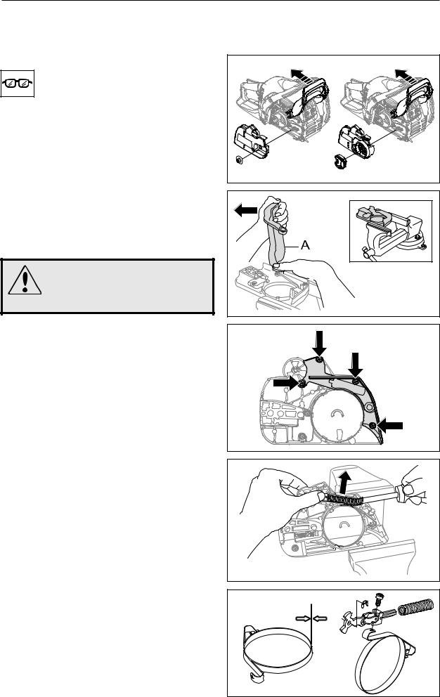
6.1 Dismantling the chain brake
1
Release the brake by moving the front hand guard backward. Loosen the bar nut and remove the clutch cover, chain and bar (see figure 1).
2
Carefully tighten the clutch housing in a vice. Release the brake by using the saw's front hand guard (A) as a tool. Mesh with the brake and tighten anti-clockwise until the brake is activated. (see figure 2)
WARNING!
Exercise care to ensure the spring does not fly out and cause personal injury. Wear protective glasses.
Fig 1 |
Fig 2 |
3
Loosen the screws and carefully remove the cover over the brake spring. (see figure 3)
Fig 3
4
Hold one hand over the brake spring; press a narrow screwdriver in between the rear section of the spring and the clutch cover. Carefully pry upward until the spring releases and runs onto the screwdriver shaft. (see figure 4)
Cleaning and inspection
• Carefully clean and check all parts. Parts must be replaced if cracked or show signs of other defects. Always use original spare parts.
• Measure the thickness of the chain brake band. It must not be less than 0.6 mm at any point. (see figure 5)
• Lubricate the knee joint with grease.
Fig 4
min 0,6 mm
Fig 5
English – 17
Safety equipment
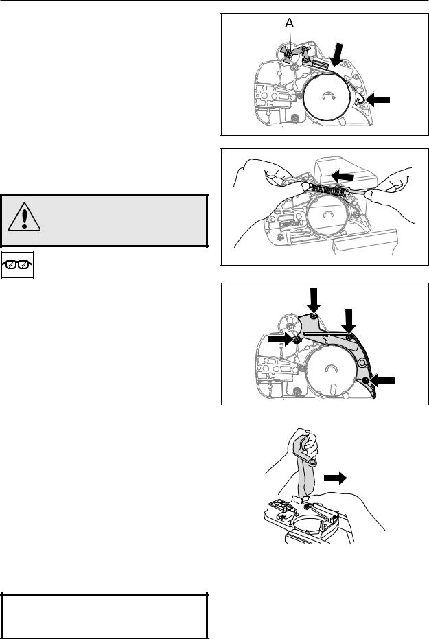
6.2 Chain brake – reassembly
1
Bolt the elbow joint to the brake band (see figure 5) and tighten to a torque of 1–1.5 Nm.
Locate the elbow joint and connected brake band in their recesses in the clutch cover. Lubricate the recess for the spring with grease (see figure 6).
Secure the circlip (A) (see figure 6).
Fig 6
2
Grip the clutch cover in a vice. Compress the spring with special tool 502 50 67-01 and push it down with your thumb (see figure 7).
WARNING!
Make sure the spring does not fly out and cause injury. Wear eye protection.
Fig 7
3
Fit the cover over the chain brake spring, tightening the screws to a torque of 1–1.5 Nm (see figure 8).
|
|
Fig 8 |
4 |
|
|
|
|
|
Tension the brake spring by using the kickback |
|
|
guard from the saw as a tool. Engage it with the |
|
|
brake mechanism and turn clockwise to release |
|
|
the brake (see figure 9). |
|
|
5 |
|
|
Turn the chain tensioner anticlockwise as far as it |
|
|
will go. |
|
|
Refit: |
|
|
• |
guide bar |
Fig 9 |
• |
chain |
|
• |
clutch cover |
|
NOTE!
After completing the repair the chain brake must be tested as described below.
18 – English
 Loading...