


Jonsered 2036 Workshop Manual

1
Workshop Manual
Chain Saws
Contents
This manual covers models:
2036/2040
2041/2045/2050
2054/2055
625/630/670
2077/2083
2095
General recommendations 2
1. Safety equipment 3
2. Starter unit 17
3. Electrical system 23
4. Fuel system 35
5. Centrifugal clutch 55
6. Lubrication system 65
7. Cylinder and piston 77
8. Crankshaft and crankcase 93
9. Tools 115
10. Technical data 127

2
502 51 02-01
General recommendations
Keep this in mind:
– Do not start the engine without the clutch and clutch drum fitted.
– Do not touch hot parts such as the silencer and clutch before
they have cooled sufficiently to avoid burn injuries.
– Avoid getting petrol on bare skin or in the mouth.
– Wipe up spilled oil immediately from the floor to avoid slipping
and subsequent injury.
– Do not use tools which are worn or fit badly, e.g. nuts and
screws.
– Never start the engine indoors. Exhaust fumes are toxic!
+ Always work on a tidy work bench.
+ Always work methodically to be sure that all parts are correctly
assembled and that screws and nuts are tightened.
+ Use protective cream on your hands. It reduces the risk of
infection and enables dirt to be more easily washed off.
Prolonged contact with motor oil can be hazardous to health.
+ Use special tools when so recommended in order to work
correctly.
Fire hazard
Handle petrol with respect since it is highly inflammable.
Do not smoke and make sure that there are no naked flames or
sparks in the vicinity.
Make sure that there is a functioning fire extinguisher in the vicinity.
Do not attempt to extinguish a petrol fire with water.
Toxic fumes
Read the instructions carefully when using cleaning liquids.
Make sure that there is adequate ventilation when handling petrol,
trichloroethylene and other viscous liquids.
The engine exhaust fumes are toxic. T est run the engine only when
there is good ventilation, preferably outdoors.
Special tools
Some work operations in this workshop manual require the use
of special tools. In each section where this is appropriate the tool
and order number are illustrated.
We recommend the use of special tools partly to avoid personal
injury and partly to eliminate expensive damage to the
components in question.
Sealing surfaces and gaskets
Make sure that all sealing surfaces are clean and free from the
residue of old gaskets. Use a tool which will not damage the
sealing surface when cleaning it. Scratches and irregularities
are removed with a fine, float cut file.
Sealing rings
Always replace a sealing ring which has been dismantled. The
sensitive sealing lip can easily be damaged and result in poor
sealing capacity. The surface which the seal seals must also be
completely undamaged. Lubricate the sealing lip with grease
before it is fitted and make sure that it is not damaged, e.g. by
shoulder and splines on a shaft. Use tape or conical sleeve as
protection. It is important that the sealing ring is correctly turned
for it to function as intended.
The engine exhaust from this product
contains chemicals known to the State
of California to cause cancer, birth
defects or other reproductive harm.
WARNING
!

3
Safety equipment
1
1.
Contents
Dismantling 4
Disassembly 4
Fitting 6
Dismantling, mod. 2054/2055 7
Fitting, mod. 2054/2055 9
Dismantling, mod. 2077/2083 10
Fitting, mod. 2077/2083 11
Checking of automatic function 12
Checking of brake action 13
Chain catcher 13
Throttle lock 13

4
Safety equipment
1
!
505 38 17-05
!
In addition to the chain brake the chain catcher and
right-hand guard on the rear handle are also considered part of the chain saw’s safety equipment.
It is obviously important that the chain brake
functions as intended, but it is also important that
the chain catcher is undamaged and in position. In
the event of a chain break this will catch up the
chain so that the hand will not be injured.
WARNING!
Protective goggles must be
worn during all work on the
chain brake to prevent personal injury if for some reason the
brake spring should fly off.
Dismantling
Dismantle the chain brake from the chain
saw.
Disassembly
Release the chain brake.
Press out the one half of the hand guard’s
bearing.
Press out the other half of the hand guard’s
bearing.
Dismantling
Remove the guide bar's attachment nuts
and lift off the clutch cover with the chain
brake.
Clean from sawdust and dirt.
WARNING!
The brake spring is tensioned with a
very large force and can cause personal injury if the brake is not
released prior to further work.
Disassembly
Release the chain brake.
Unscrew the screw to the hand guard’s
bearing completely, and then screw in
approx. 2 turns.
Drive out the bearing by tapping the screw
with a hammer.
Press out the other half of the bearing by
means of suitable mandrel, e.g.
505 38 17-05.
Lift off the hand guard.

5
Safety equipment
1
!
Remove the screws and the cover over
the brake spring.
Bend up the brake spring.
Press out the toggle-joint’s bearing pin
and lift off the complete brake mechanism.
Press out the plate spring with a suitable
mandrel.
Remove the screws and lift off the cover
over the brake spring.
WARNING!
The brake spring is tensioned and
can slip out of its position.
Use a screwdriver and carefully bend up
the spring.
Press out the toggle-joint’s bearing pin by
means of a suitable mandrel.
Lift off the complete brake mechanism.
Press out the plate spring with a suitable
mandrel, and replace if necessary.
Clench the spring eye with a pair of pliers
so that it is easier to fit the new spring.

6
Safety equipment
1
0,8 mm
The brake band must have a minimum
thickness of 0.8 mm at the most worn
point.
Remove the screw and replace the brake
band.
Dismantle the lock-ring and the pin in
order to replace the spring inside the
hand guard.
Assembly
Grease the spring and fit it in the hand
guard.
Check the wear on the brake band.
At the most worn point the band must
have a thickness of at least 0.8 mm.
Otherwise it should be replaced with a
new band.
Remove the screw and fit a new brake
band.
Check after fitting that the brake band
does not touch the toggle-joint and obstruct its movement.
Inside the hand guard there is a spring
which is accessible for replacement after
the lock-ring and pin are dismantled.
Use a small screwdriver to remove the
lock-ring.
Assembly
Grease the spring and push it in the hand
guard as far as it goes.
Fit the pin and lock-washer.
NOTE!
The pin should not go through the eye on
the spring.
Check that the spring is turned correctly.

7
Safety equipment
1
!
A
B
Fit the brake mechanism in the clutch
cover.
Lubricate the bearing points with thin oil.
Press down the brake spring by means of
a Phillips screwdriver.
Fit the cover.
Grease the bearing surfaces and fit the
hand guard.
Check that the brake functions.
Dismantling
Mod. 2054/2055
Remove the screw, sleeve and washer
for the hand guard’s bearing on the starter unit side, including the clutch cover,
guide bar and chain.
Clean!
Place the brake mechanism in position
on the clutch cover.
Press in the toggle-joint’s bearing pin (A)
and place the tubular pin (B) in position.
Lubricate the bearing points with thin oil.
Press down the brake spring in the clutch
cover by means of a Phillips screwdriver.
WARNING!
Observe care to avoid injury if the
screwdriver slips.
Fit the cover over the spring mechanism.
Grease the bearing points for the hand
guard.
Press down the hand guard over the
bearing and fit both bearing sleeves.
NOTE!
Check that the bearing sleeves are placed
on the correct side.
Tension and release the chain brake a
number of times to check that it functions.
Dismantling
Mod. 2054/2055
On these models the chain brake’s hand
guard has an extra bearing point on the
starter unit side.
Remove the screw, sleeve and washer
for this bearing.
Remove the clutch cover, guide bar and
chain.
Clean from sawdust and dirt.

8
Safety equipment
1
Dismantle the protective plate over the
guide bar attachment and the chain brake.
Release the chain brake!
Remove the plate clamp over the brake
spring and bend away the spring.
Remove the lock-ring round the hand
guard’s bearing pin and lift off the brake
mechanism.
Replace the plate insert in the hand guard
if the pins are worn by first pressing out
the fitted pin.
Remove the protective plate over the
guide bar attachment.
Remove the screws and lift off the chain
brake.
Release the chain brake!
!
WARNING!
The brake spring is tensioned with a
very large force and can cause personal injury if the brake is not released
prior to further work.
Remove the screw and plate clamp over
the brake spring.
Carefully bend away the spring by means
of a screwdriver.
NOTE!
The spring has a certain tension even
when the brake is released, and therefore
it should be dismantled carefully.
Remove the lock-ring round the hand
guard’s bearing pin and lift off the brake
mechanism.
If the pins on the plate insert in the hand
guard are worn the complete insert can
easily be replaced.
Press out the fitted pin with a suitable
mandrel and replace the insert.

9
Safety equipment
1
0,8 mm
Dismantle the brake mechanism and
replace worn or damaged parts.
Fit the brake spring and plate clamp over
the spring.
Fit the chain brake on the crankcase.
Screw tight the cover plate over the guide
bar attachment and fit the brake’s bearing
on the starter unit side.
Dissassemble the brake mechanism and
replace worn or damaged parts.
The brake band should have a minimum
thickness of 0.8 mm at the most worn
place.
Assembly
Mod. 2054/2055
Fit the brake in the reverse order to dismantling.
Begin with by fitting the hand guard.
Lubricate all moving parts with thin oil.
Fit the brake spring by means of a Phillips
screwdriver.
WARNING!
Observe care to avoid injury if the
screwdriver slips.
!
Fit the plate clamp over the spring.
Fit the chain brake on the crankcase.
NOTE!
Make sure that the guide pin on the brake
fits into the hole in the crankcase before
the screws are tightened.
Fit the cover plate on the guide bar attachment.
Screw tight the screw for the brake’s
bearing on the starter unit side.
Do not forget the washer between the
crankcase and brake!

10
Safety equipment
1
!
Dismantling
Mod. 2077/2083
Dismantle the chain brake’s bearing on
the starter unit side.
Remove the clutch cover, guide bar and
chain.
Clean!
Remove the screws and lift off the chain
brake.
Release the chain brake!
Lift up the toggle-joint carefully by means
of a screwdriver.
Dismantle the hand guard.
Press the hand guard out of the bearing.
Dismantling
Mod. 2077/2083
Remove the screw, sleeve and washer
for the chain brake’s bearing on the starter unit side.
Remove the clutch cover, guide bar and
chain.
Clean from sawdust and dirt.
Remove the screws and lift off the chain
brake.
Release the chain brake!
!
NOTE!
The other end of the spring is controlled
by a pin which goes into the centre.
For this reason do not try to lift up the
spring there.
Dismantle the hand guard.
Remove the lock-ring by means of a small
screwdriver.
Hold your thumb over so that the ring
does not fly away.
Press out the hand guard from the bearing.
WARNING!
Observe care so that the sprin loaded
catch does not fly away.
WARNING!
The brake spring is tensioned with a
very large force and can cause personal injury if the brake is not released
prior to further work.
Lift up the toggle-joint carefully by
means of a screwdriver.
Hold your hand over.
11
Safety equipment
1
0,8 mm
Replace the hand guard’s bearing pin if it
is worn.
Press out the sprung tubular pin and pull
out the plate insert from the hand guard.
Clean and check all parts.
The thickness of the brake band should
be at least 0.8 mm.
Assembly
Mod. 2077/2083
Fit the brake in the reverse order to dismantling.
Press down the hand guard in the correct
position.
The hand guard’s bearing pin can now
easily be replaced.
Press out the spring tensioned tubular
pin and pull out the complete plate insert
from the hand guard.
Replace the insert if the bearing pin is
worn.
Clean all the parts of the chain brake and
check them for wear or damage.
The brake band should have a minimum
thickness of 0.8 mm at the most worn
part.
Replace the brake band if it is worn more
than this.
Assembly
Mod. 2077/2083
Fit the brake in the reverse order to dismantling.
Begin by fitting the hand guard.
Lubricate the bearing pin and catch with
oil.
Place the catch in position with the
extruding part downwards.
Press away the catch by means of a
screwdriver and press down the hand
guard in the correct position.
Fit the lock-ring on the bearing pin.

12
Safety equipment
1
A
B
Fit the brake band (A) and place the
toggle-joint in position over its bearing
pin (B).
Press together the brake spring far
enough so that the guide pin in the back
of the spring housing is released.
Press down the spring and check that the
pin goes into the centre of the spring.
Press down the brake band in its rear
attachment (A).
Place the toggle-joint in position over its
bearing pin (B).
Make sure that it is correctly positioned.
Press the brake spring over the guide pin.
Push the guide sleeve in the spring and
outside of the guide pin.
Press the spring together by means of a
suitable Phillips screwdriver far enough
so that the guide pin in the back edge of
the spring housing is released.
Press down the spring and check that the
pin goes into the centre of the spring.
Fit the chain brake on the engine.
Check that the guide pin on the chain
brake goes into the corresponding hole in
the crankcase.
L
H
Checking of the automatic function
NOTE!
The engine should be switched off during this check.
Hold the saw approx. H mm over a stable object.
Release the front handle and allow the saw to turn round the back handle by virtue of
its own weight. When the guide bar point hits the object the brake should be activated.
H, cm/inch L, inch
45/14 11 – 16
55/22 18 – 22
65/26 24 – 28
80/32 30 – 36

13
Safety equipment
1
Checking of the brake
effect
Start the engine.
Hold the handle with both hands and rev
up.
Release the chain brake by turning the
left wrist towards the hand guard without
releasing the grip round the front handle.
The chain should stop immediately.
Chain catcher
Replace the chain catcher if it is deformed
or cracked.
Checking of the brake
effect
Place the saw on a stable surface and
start the engine.
Hold the handle with both hands and rev
up.
Release the chain brake by turning the
left wrist towards the hand guard without
releasing the grip round the front handle.
The chain should stop immediately.
Chain catcher
The chain catcher has the purpose of
catching the chain if it breaks.
It is therefore important that it is not
deformed or cracked. Replace if this
should be the case.
Throttle lock
Dismantling
Remove the screws.
Remove the handle half, throttle control
and lock.
Throttle lock
Dismantling
Remove the screws which hold the handle
halves together and where appropriate
also the screw which holds the spring for
the vibration damper.
Lift off the handle half and throttle control
together with the lock.

14
Fitting, mod. 2036/2040
Fit in the reverse order to dismantling.
2
1
Safety equipment
1
Check that the throttle cable is correctly
fitted.
Do not lubricate!
Fitting mod. 2041/2045/2050
Check that the throttle cable is correctly
fitted.
Do not lubricate!
Fitting mod. 2054/2055
Check that the spring and throttle cable
are correctly connected.
Fitting mod. 2036/2040
Replace any damaged parts and fit in the
reverse order to dismantling.
Note the following:
● Make sure that the spring comes on
the correct side of the barrier in the
throttle control.
● Check that the throttle cable's ball lug
sits in the recess (1).
● Check that the throttle cable is flush
with the cam curve on the throttle
control (2).
● Do not lubricate!
Fitting mod. 2041/2045/2050
Note the following:
● Fit the throttle cable from the correct
side in the throttle control.
● Check that the throttle cable is
correctly positioned so that it is not
clenched when the handle half is fitted.
● Do not lubricate!
Fitting mod. 2045/2055
Note the following:
● The positioning of the spring in the
throttle control.
● The connection of the throttle cable
from underneath to the throttle control
catch.
● Do not lubricate!

15
Safety equipment
1
Dismantling mod. 625/630/670
Press out the fitted pin and dismantle the
cover.
Dismantle the spring and throttle control
lock.
Fitting mod. 625/630/670
Fit the throttle control lock in the reverse
order to dismantling.
Dismantling mod. 2095
Dismantle the handle half.
Dismantling mod. 625/630/670
Press out the fitted pin approx. 13-14 mm
so that the throttle control lock comes
loose.
Dismantle the covers by means of pressing a screwdriver into the back edge of
the covers.
If the handle is electrically heated see
chap. 3 ”Electrical system”.
Press out the sprung tubular pin which is
located behind the cover far enough so
that the spring and the throttle control
lock can be lifted off.
Fitting mod. 625/630/670
Replace damaged or worn parts and fit in
the reverse order to dismantling.
NOTE!
The sprung tubular pin should go through
the spring eyelet.
Dismantling mod. 2095
Remove the screws and lift off the handle
half.

16
1
2
Safety equipment
1
Fitting mod. 2095
Replace damaged or worn parts and fit in
the reverse order to dismantling.
Fitting mod. 2095
Replace damaged or worn parts.
Fit in the reverse order to dismantling.
Pay attention to the following:
● The spring’s straight shank should be
fitted in the throttle control lock (1).
● Make sure the throttle wire housing is
well pressed down in the recess (2).
● Check that the short-circuiting cable
sits in the recess so that it is not
clenched when the handle half is
screwed tight.

17
Contents
Dismantling 18
Replacement of return spring 19
Replacement of starter cord 20
Assembly 21
Replacement of starter pawls 22
Starter unit
2.
2

18
2
Starter unit
WARNING!
When working on the starter unit wear protective glasses to avoid eye injuries in the
event that the return spring flies out.
!
Dismantling
1. Dismantle the starter from the engine
unit.
Dismantling
1. Remove all screws and lift off the
starter.
2. Release the spring tension.
2. Release the spring tension.
Pull out the starter cord approx. 30
cm. Brake the cord wheel with the
thumb and place the cord in one of the
recesses on the pulley.
3. Allow the pulley to slowly rotate backwards.
3. Allow the pulley to slowly rotate backwards.
NOTE!
Brake the rotation with the thumb.
WARNING!
Observe care so that the thumb is not
injured by the reinforcement ribs on
the pulley or the cord's attachment
screw.
!

19
Starter unit
2
!
!
!
!
4. Remove the screw and the washer.
5. Remove the pulley and spring cassette, and return spring.
4. Remove the screw and washer in the
centre of the pulley.
5. Lift off the pulley carefully.
6A.Remove the screws which hold the
spring cassette and lift off.
WARNING!
Wear protective glasses. The return spring
can fly out and cause
injury.
WARNING!
Wear protective glasses.
6B.Remove the screws which hold the
cover disc over the return spring.
Dismantle the spring by giving the
starter housing a sharp tap against
the work bench with the spring turned
downwards.
WARNING!
Wear protective glasses.
WARNING!
Wear protective glasses. The return spring
can fly out and cause
injury.
Replacing return spring
Dismantle the pulley as described above.
A. Fit a new spring cassette.
Replacing return spring
Dismantle the pulley as described above.
A. Place a new spring cassette in the
starter housing and tighten the
screw(s).
6. Dismantle the cover disc and return
spring from the starter unit housing.

20
2
Starter unit
!
!
B. Press down a new spring in the starter
housing.
B. Return spring without cassette.
Leave the lock shackle round the
spring in position.
1. Place the spring over its seat in the
starter housing.
2. Press down the spring in the correct
position by means of the thumbs and
let the lock shackle slide over the
spring.
3. Fit the cover plate off the spring.
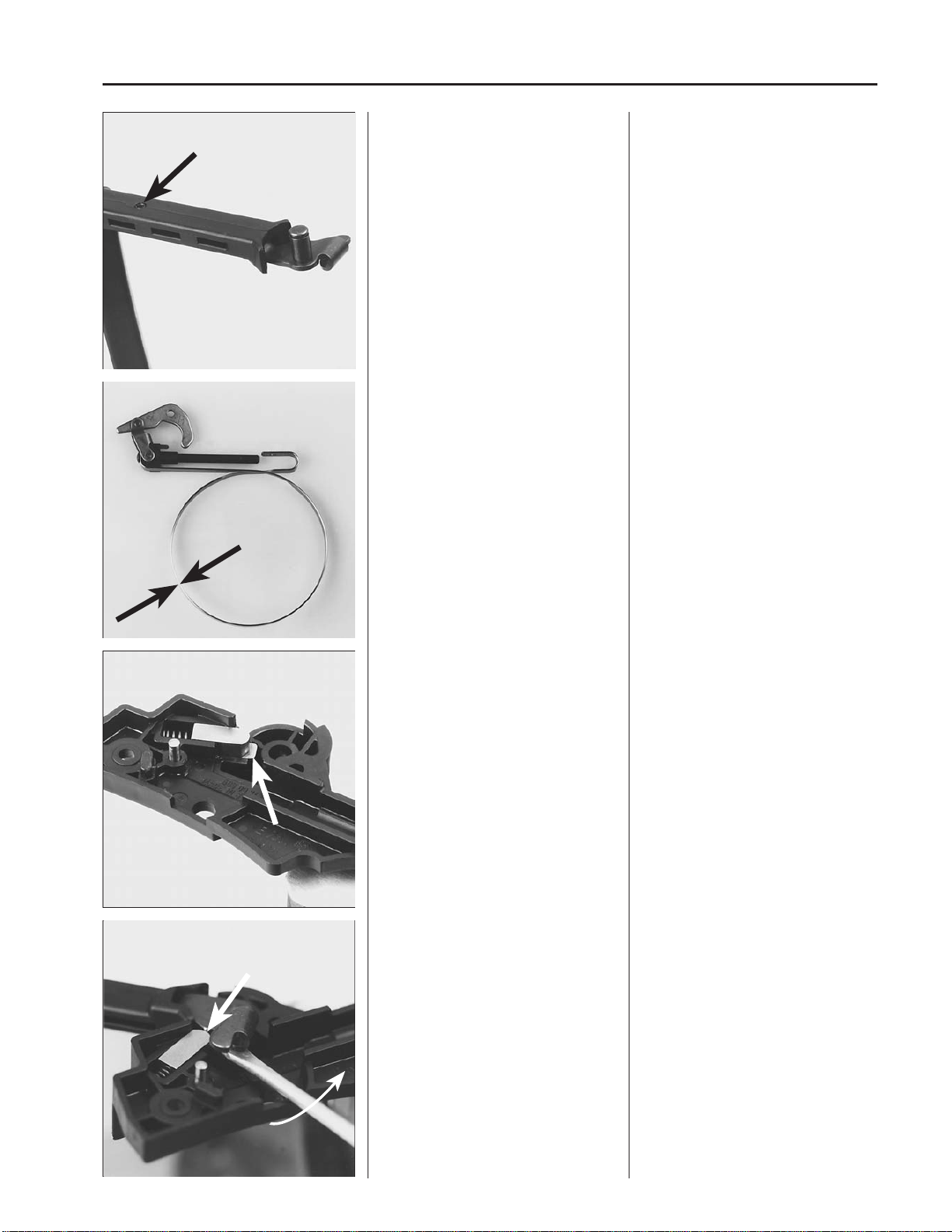
Replacing starter cord
1. Fit and lock the cord at the pulley as
per one of the methods shown in the
diagrams.
Tips!
The knot on the starter cord in the starter
handle may be difficult to untie. It is easier
if the knot is first knocked with a hammer
against a hard surface.
2. Anchor the cord in the starter handle. 2. Enter the cord through the socket in
the starter housing and anchor it in
the starter handle by means of a knot.
Fold down the free end and pull the
knot securely into the handle.
WARNING!
Wear protective glasses.
WARNING!
Wear protective glasses.

21
Starter unit
2
1 – 3 r
+ 1/2 r
max
Assembly
1. Wind the cord approx. 4 turns clockwise round the pulley.
2. Fit the pulley.
3. Increase the spring tension.
4. Check the spring tension.
With a fully withdrawn cord it should
be possible to turn the pulley
at least
another half turn.
Assembly
1. Wind the cord approx. 4 turns clockwise round the pulley.
2. Lubricate the pulley’s bearing pin and
the return spring with a few drops of
motor oil or non-freezing lubricant and
fit the pulley.
Check that the return spring grips the
pulley. The spring may require to be
bent out further from the bearing pin.
3. Put the washer in place and tighten
the screw.
4. Increase the spring tension.
With a fully withdrawn cord it should
be possible to turn the pulley
at least
another half turn.
Tension the spring more by:
● Pulling the cord approx. 30 cm and
braking the pulley with the thumb.
● Lift up the cord in one of the recesses
on the pulley.
● Wind the cord 1-3 turns clockwise
round the hub of the pulley.
● Pull out the starter cord fully.
5. Check the spring tensions.
With a fully withdrawn cord it should
be possible to turn the pulley
at least
another half turn.
Repeat the spring tensioning if
necessary.

22
2
Starter unit
503 21 22-01
5. Assemble the starter in the reverse
order to dismantling.
Replacing starter pawls
See chapter 3 ”Electrical system”.
6. Assemble the starter.
Pull out the starter cord a little. Put the
starter in position. Release the starter
cord and check that the pawls grip the
pulley.
Tighten the screws.
NOTE!
If the threads in the crankcase (made of
plastic) are for any reason damaged an
oversize screw (No. 503 21 22-01) is
recommended.
Replacing starter pawls
See chapter 3 ”Electrical system”.

23
Electrical system
3.
3
Contents
Checking ignition spark 24
Replacing spark plug protection 26
Dismantling 28
Starter pawls 20
Assembly 30
Electrically heated handles 31
Replacing the generator 33

24
3 Electrical system
502 71 13-01
Checking ignition spark
Clean the electrodes and check the
electrode gap.
If the electrodes are worn down more
than 50% the plug should be replaced.
Check if there is a spark when starting.
Try with test plug No. 502 71 13-01 if
there is no spark.
Checking ignition spark
Remove the plug and clean from soot by
means of steel brush.
Check the electrode gap. It should be 0.5
mm – 0.7 mm (.020 – .028").
Adjust the gap to correct value with side
electrode.
If the electrodes are worn down more
than 50 % the plug should be replaced.
An overlarge gap implies stress on the
ignition module and the risk of short
circuiting.
Make sure that the stop contact is in start
position.
Earth the plug to the cylinder and pull the
start handle.
There should be a spark between the
electrodes.
If there is no spark try with the test plug
No. 502 71 13-01.
If there is a spark the fault lies in the plug.
Replace plug.
The chain saw is fitted with an electronic system
consisting of flywheel, ignition coil, and trigger
unit. Certain saw models are fitted with a generator system to heat the handles and carburettor.
The ignition system is electronic and completely
without moving parts. A defective component
cannot be repaired and must be replaced.
The ignition spark in an electronic ignition system has a very short burn time and may therefore
be experienced as weak and sometimes difficult
to see during trouble shooting.
NOTE!
When testing the chain saw’s heating system the
guide bar, chain and clutch cover must be fitted
before the engine is started!

25
Electrical system
3
A
B
Try with a new plug
If there is no spark disconnect the short
circuiting contact.
Replace the contact if necessary.
Try with a new plug.
If there is still no spark remove the short
circuiting cable from either the ignition
module or short circuiting contact.
If there is no spark the fault lies in the stop
contact.
Replace the contact.
Check the connections of the ignition
cable.
Still no spark?
Check the plug connection.
Pull off the rubber protection at the plug
(A) and ignition module (B) and check
that the ignition cable is undamaged. Cut
off a piece of the cable to ensure good
contact.
Lubricate the cable ends with a little
grease to simplify fitting and prevent
moisture from penetrating into the connections.
Lubricate the cable ends with grease.
Mod. 2077/2083
Check that the earth cable is undamaged
and that it has metallic contact with the
crankcase.
Mod. 2077/2083
Check that the earth cable between the
crankcase and stop contact is undamaged
and that it has metallic contact with the
crankcase.
Use an ohm-meter and measure the
resistance in the cable between the stop
contact and connection at the crankcase.
The instrument should give a full reading
if the cable is in good condition.

26
3
Electrical system
502 51 34-05
0.3 mm
502 50 06-01
Check other cables and connections. Still no spark?
Check the other cables and connections
for poor contact (dirt, corrosion, cable
break and damaged insulation).
Tips!
Use an Ohm-meter to check if there is a
cable break, e.g. as a result of pinching.
Check the air gap.
Adjust the air gap.
Replacing spark plug
protection
1. Take ignition cable through the spark
plug protection.
2. Make a hole in the ignition cable for
the contact spiral.
Still no spark?
Check the air gap between the flywheel
permanent magnet and ignition module.
The gap should be 0.3 mm (.012").
Use air gap measure 502 51 34-05.
Adjust the air gap to correct size.
● Release screws.
● Place the feeler gauge and press the
ignition module to the flywheel.
● Tighten the screws and check the air
gap again.
If there is still no spark the ignition system
should be replaced.
Replacing spark plug
protection
1. Lubricate the ignition cable with a little
grease and take it through the plug
protection.
2. Cut off a piece of the ignition cable
(approx. 5 mm, .20") and make a hole
in the cable for the contact spiral by
means of pliers No. 502 50 06-01.

27
3
Electrical system
504 91 06-05
3. Fit the contact spiral on the ignition
cable.
3. Fit the contact spiral on the ignition
cable and make sure that the wire is
folded along the cable.
4. Pull the contact spiral into the spark
plug protection.
NOTE!
It is important that the point of the contact
spiral meets the middle of the ignition
cable to prevent sparking.
Fit a piston stop No. 504 91 06-05 alt.
502 50 33-01 in the spark plug hole.
Fit a piston stop No. 504 91 06-05 alt.
502 50 33-01 in the spark plug hole.
Make sure that the piston stop is screwed
down to the bottom.
Dismantle the starter pawls.
Mod. 2054/2055
On earlier versions of these models the
starter pawls sit on a bridge which can be
lifted off when the flywheel nut is
dismantled.
Dismantling
Dismantle the plug, cylinder cover, starter unit, and air bar.
Dismantle the ignition module and release the other cable connections.
Dismantling
Dismantle the plug, cylinder cover, starter unit, and air conductor.
Dismantle the ignition module by removing the two screws.
Release the other cable connections and
lift off the ignition module.
Dismantle the starter pawls by releasing
the screws. Make sure that the small
washer close to the flywheel is not mislaid.
Mod. 2054/2055
On earlier versions of these models the
starter pawls sit on a bridge which can be
lifted off when the flywheel nut is
dismantled.

28
3
Electrical system
502 51 49-01
502 51 94-01
Mod. 2036/2040
Dismantle the flywheel by using a
hammer.
Mod. 2036/2040
Thread the nut on the shaft to protect the
threads.
Snap the springs loose and fold down the
starter pawls to leave space for the
hammer.
Grip the flywheel and lift up the engine
unit.
Give a few smart blows with the hammer
on the flywheel nut until the flywheel
releases from the shaft.
Tips!
Use a pressure piece to protect the
threads on the shaft and so that it is also
easier to use the hammer.
Remove the flywheel nut.
Pull off the flywheel.
Tips!
If the flywheel is tight give a few smart
taps with a hammer on the extractor screw.
Remove the flywheel nut by means of a
suitable socket wrench.
Pull off the flywheel by means of withdrawing tool 502 51 49-01 which is
screwed in the hole for the starter pawls.
NOTE!
Centre the withdrawing tool over the shaft
centre. Select suitable screws and tighten
the withdrawing tool.
Tips!
The flywheel may sit very tightly on the
shaft.
To simplify dismantling give a few smart
taps with a hammer on the extractor
screw. Hold the chain saw in the air with
the handle on the withdrawing tool.

29
3
Electrical system
504 90 90-01
Mod. 2054/2055
Pull off the flywheel.
Mod. 2054/2055
Pull off the flywheel by means of ball
bearing puller No. 504 90 90-01.
NOTE!
The claws on the tool should be placed on
and opposite the permanent magnet on
the flywheel so that this is not damaged.
Is the flywheel stuck?
Lift up the engine unit by holding the tool
and hit the tool screw a few times with a
hammer.
Starter pawls
Check the starter pawls for wear and
damage.
Replace damaged parts.
Starter pawls
Check the starter pawls for wear and
damage.
Replace damaged parts.
For starter pawls which are mounted on a
separate bridge the entire unit must be
replaced.
Mod. 2036/2040
Press out the journals by means of a
suitable mandrel.
Replace damaged parts.
Mod. 2036/2040
Replace the starter pawls and springs in
the following way if they are housed on a
journal pressed in the flywheel.
Place the flywheel on support blocks and
press out the journals by means of a
suitable mandrel.
Replace damaged parts.
Make sure that the spring is not pinched
when the journal is pressed into the
flywheel.
Check that the starter pawls move easily.

30
3
Electrical system
0.3 mm
Assembly
Check that the keyway and key in the
crankshaft are undamaged.
Assembly
Check that the keyway and key in the
crankshaft are undamaged.
Fit a new key and make sure that it fits
correctly in the keyway.
Check that the keyway and the cast key
respectively in the flywheel are undamaged.
Fit the flywheel.
Check that the keyway and cast key
respectively in the flywheel are undamaged.
Fit the flywheel on the crankshaft and
check that the key and keyway are
correctly positioned before the flywheel
nut is tightened.
Tighten the nut to a torque of 25–35 Nm
Fit the ignition module.
Adjust the air gap (0.3 mm, .012")
Fit the other cables.
Fit the other parts in the reverse order to
dismantling.
Fit the ignition module
Adjust the air gap to the correct size
(0.3 mm, .012").
See also page 26.
Fit the other cables and make sure that
they are correctly positioned in cable
grooves etc. so that they cannot be
damaged.
Fit the other parts in the reverse order to
dismantling.
When fitting the starter pawls check the
following:
● Washer between flywheel and starter
pawls.
● The spring is not clenched.
● The starter pawls move freely.
● Use Locktite on the screw.
 Loading...