


 Loading...
MicroLogix™ Ethernet Interface (ENI)
(Cat. No. 1761-NET-ENI)
User Manual
Important User Information Because of the variety of uses for the products described in this publication, those responsible for the application and use of this
control equipment must satisfy themselves that all necessary steps have been taken to assure that each application and use meets all performance and safety requirements, including any applicable laws, regulations, codes and standards.
The illustrations, charts, sample programs and layout examples shown in this guide are intended solely for purposes of example. Since there are many variables and requirements associated with any particular installation, Allen-Bradley does not assume responsibility or liability (to include intellectual property liability) for actual use based upon the examples shown in this publication.
Allen-Bradley publication SGI-1.1, Safety Guidelines for the Application, Installation and Maintenance of Solid-State Control
(available from your local Allen-Bradley office), describes some important differences between solid-state equipment and electromechanical devices that should be taken into consideration when applying products such as those described in this publication.
Reproduction of the contents of this copyrighted publication, in whole or part, without written permission of Rockwell Automation, is prohibited.
Throughout this manual we use notes to make you aware of safety considerations:
ATTENTION
Identifies information about practices or circumstances that can lead to personal injury or
!death, property damage or economic loss
Attention statements help you to:
•identify a hazard
•avoid a hazard
•recognize the consequences
IMPORTANT |
Identifies information that is critical for successful |
|
application and understanding of the product. |
||
|
Allen-Bradley is a trademark of Rockwell Automation
|
Table of Contents |
|
Preface |
Who Should Use this Manual. . . . . . . . . . . . . . . . . . . . . . . |
P-1 |
|
Purpose of this Manual . . . . . . . . . . . . . . . . . . . . . . . . . . . |
P-1 |
|
Common Techniques Used in this Manual . . . . . . . . . . . . . |
P-2 |
|
Rockwell Automation Support . . . . . . . . . . . . . . . . . . . . . . |
P-3 |
|
Chapter 1 |
|
Product Overview |
Ethernet Connection . . . . . . . . . . . . . . . . . . . . . . . . . . . . . |
1-1 |
|
Non-Ethernet Devices . . . . . . . . . . . . . . . . . . . . . . . . . . . . |
1-1 |
|
Hardware Features . . . . . . . . . . . . . . . . . . . . . . . . . . . . . . |
1-2 |
|
Operating Modes . . . . . . . . . . . . . . . . . . . . . . . . . . . . . . . |
1-4 |
|
Device Compatibility . . . . . . . . . . . . . . . . . . . . . . . . . . . . . |
1-4 |
|
Ethernet Networks . . . . . . . . . . . . . . . . . . . . . . . . . . . . . . |
1-5 |
|
Chapter 2 |
|
Installation and Wiring |
European Communities (EC) Directive Compliance . . . . . . |
2-1 |
|
Safety Considerations . . . . . . . . . . . . . . . . . . . . . . . . . . . . |
2-2 |
|
Mounting . . . . . . . . . . . . . . . . . . . . . . . . . . . . . . . . . . . . . |
2-3 |
|
ENI Port Identification. . . . . . . . . . . . . . . . . . . . . . . . . . . . |
2-5 |
|
External Power Supply Wiring . . . . . . . . . . . . . . . . . . . . . . |
2-5 |
|
Ethernet Connections . . . . . . . . . . . . . . . . . . . . . . . . . . . . |
2-6 |
|
RS-232 Port Connections . . . . . . . . . . . . . . . . . . . . . . . . . . |
2-8 |
|
Chapter 3 |
|
Operation |
Operation Overview . . . . . . . . . . . . . . . . . . . . . . . . . . . . . |
3-1 |
|
Allocation of Ethernet Connections . . . . . . . . . . . . . . . . . . |
3-1 |
|
ENI Functional Overview . . . . . . . . . . . . . . . . . . . . . . . . . |
3-2 |
|
Program Upload/Download and On-Line Sessions . . . . . . . |
3-2 |
Chapter 4
ENI Configuration (Node 248 to 254)
Peer-to-Peer Messaging
Configuration Methods . . . . . . . . . . . . . . . . . . . . . . . . . . . 4-1
ENI Configuration Utility . . . . . . . . . . . . . . . . . . . . . . . . . . 4-1
Controller Messaging. . . . . . . . . . . . . . . . . . . . . . . . . . . . . 4-5
Configuring ENI Data Parameters. . . . . . . . . . . . . . . . . . . . 4-6
Configuring ENI String Parameters . . . . . . . . . . . . . . . . . . . 4-8
ENI Configuration Parameters . . . . . . . . . . . . . . . . . . . . . . 4-10
Chapter 5
Messaging Between the ENI and DF1 Devices . . . . . . . . . . 5-1 Message to Configuration Nodes (Nodes 100 to 149) . . . . . 5-3 Sending a Message to a Destination Controller
(Nodes 0 to 49). . . . . . . . . . . . . . . . . . . . . . . . . . . . . . . . . 5-4
Publication 1761-UM006A-EN-P - February 2001
Table of Contents |
ii |
|
|
E-Mail Messages (Node 50 to 99)
Connecting 1769-L20 CompactLogix Controllers on Ethernet
Troubleshooting
Specifications
BOOTP Configuration Method (default)
Chapter 6
Overview . . . . . . . . . . . . . . . . . . . . . . . . . . . . . . . . . . . . . 6-1
Configuring E-Mail . . . . . . . . . . . . . . . . . . . . . . . . . . . . . . 6-2
Sending an E-Mail Message . . . . . . . . . . . . . . . . . . . . . . . . 6-5
Chapter 7
System Diagram . . . . . . . . . . . . . . . . . . . . . . . . . . . . . . . . 7-1 Purpose . . . . . . . . . . . . . . . . . . . . . . . . . . . . . . . . . . . . . . 7-2 Scope . . . . . . . . . . . . . . . . . . . . . . . . . . . . . . . . . . . . . . . . 7-2 General Ethernet Information . . . . . . . . . . . . . . . . . . . . . . 7-3 Configuring 1761-NET-ENI #1 . . . . . . . . . . . . . . . . . . . . . . 7-4 Configuring 1761-NET-ENI #2 . . . . . . . . . . . . . . . . . . . . . . 7-6 Configure RSLINX and Download the Program
To the 1769-L20 . . . . . . . . . . . . . . . . . . . . . . . . . . . . . . . . 7-13 Create MSG Programs for the SLC 5/05 and
the 5550 Controllers . . . . . . . . . . . . . . . . . . . . . . . . . . . . . 7-15 Configuring an Ethernet Driver in RSLINX . . . . . . . . . . . . . 7-21
Chapter 8
Network Troubleshooting . . . . . . . . . . . . . . . . . . . . . . . . . 8-1 LED Sequence at Power-Up. . . . . . . . . . . . . . . . . . . . . . . . 8-1 Troubleshooting Using the LED Indicators . . . . . . . . . . . . . 8-2 Error Codes Generated by the ENI. . . . . . . . . . . . . . . . . . . 8-3 Message Instruction Error Codes . . . . . . . . . . . . . . . . . . . . 8-3
Appendix A
Physical Specifications. . . . . . . . . . . . . . . . . . . . . . . . . . . . A-1
Ethernet Specifications . . . . . . . . . . . . . . . . . . . . . . . . . . . A-1
MicroLogix Web Site . . . . . . . . . . . . . . . . . . . . . . . . . . . . . A-1
Dimensions. . . . . . . . . . . . . . . . . . . . . . . . . . . . . . . . . . . . A-2
Appendix B
Using BOOTP . . . . . . . . . . . . . . . . . . . . . . . . . . . . . . . . . . B-2
Run the Boot Server Utility . . . . . . . . . . . . . . . . . . . . . . . . B-5
Glossary
Index
Publication 1761-UM006A-EN-P - February 2001

Preface
Who Should Use this Manual
Purpose of this Manual
Read this preface to familiarize yourself with the rest of the manual. It provides information concerning:
•who should use this manual
•the purpose of this manual
•related documentation
•conventions used in this manual
•Rockwell Automation support
Use this manual if you are responsible for designing, installing, programming, or troubleshooting control systems that use Allen-Bradley Controllers on Ethernet.
You should have a basic understanding of Allen-Bradley programmable controllers and Ethernet networking. You should understand programmable controllers and be able to interpret the ladder logic instructions required to control your application. If you do not, contact your local Allen-Bradley representative for information on available training courses before using this product.
This manual is a reference guide for the Ethernet Interface (ENI). It describes the procedures you use to install and configure the ENI.
This manual:
•gives you an overview of the ENI
•explains the procedures you need to install and use an ENI
Publication 1761-UM006A-EN-P - January 2001

Preface P-2
Related Documentation
The following documents contain additional information concerning
Rockwell Automation products. To obtain a copy, contact your local
Rockwell Automation office or distributor.
For |
Read this Document |
Document Number |
|
|
|
Instructions on installing a 1761-NET-ENI Interface Converter. |
Ethernet Interface Installation |
1761-IN006A-MU-P |
|
Instructions |
|
|
|
|
Information on DF1 open protocol. |
DF1 Protocol and Command Set |
1770-6.5.16 |
|
Reference Manual |
|
|
|
|
In-depth information on grounding and wiring Allen-Bradley |
Allen-Bradley Programmable |
1770-4.1 |
programmable controllers |
Controller Grounding and Wiring |
|
|
Guidelines |
|
|
|
|
A description of important differences between solid-state |
Application Considerations for |
SGI-1.1 |
programmable controller products and hard-wired electromechanical |
Solid-State Controls |
|
devices |
|
|
|
|
|
An article on wire sizes and types for grounding electrical equipment |
National Electrical Code - Published by the National Fire |
|
|
Protection Association of Boston, MA. |
|
|
|
|
A complete listing of current documentation, including ordering |
Allen-Bradley Publication Index |
SD499 |
instructions. Also indicates whether the documents are available on |
|
|
CD-ROM or in multi-languages. |
|
|
|
|
|
A glossary of industrial automation terms and abbreviations |
Allen-Bradley Industrial Automation |
AG-7.1 |
|
Glossary |
|
|
|
|
Common Techniques Used in this Manual
The following conventions are used throughout this manual:
•Bulleted lists such as this one provide information, not procedural steps.
•Numbered lists provide sequential steps or hierarchical information.
•Italic type is used for emphasis.
Publication 1761-UM006A-EN-P - January 2001

Preface P-3
Rockwell Automation
Support
Rockwell Automation offers support services worldwide, with over 75 Sales/Support Offices, 512 authorized Distributors and 260 authorized Systems Integrators located throughout the United States alone, plus Rockwell Automation representatives in every major country in the world.
Local Product Support
Contact your local Rockwell Automation representative for:
•sales and order support
•product technical training
•warranty support
•support service agreements
Technical Product Assistance
If you need to contact Rockwell Automation for technical assistance, please review the Troubleshooting information on page 8-1 in this manual first. Then call your local Rockwell Automation representative.
Your Questions or Comments on this Manual
If you find a problem with this manual, or you have any suggestions for how this manual could be made more useful to you, please contact us at the address below:
Rockwell Automation
Control and Information Group
Technical Communication, Dept. A602V
P.O. Box 2086
Milwaukee, WI 53201-2086
or visit our internet page at:
http://www.rockwellautomation.com
Publication 1761-UM006A-EN-P - January 2001

Preface P-4
Publication 1761-UM006A-EN-P - January 2001

Chapter 1
Ethernet Connection
Non-Ethernet Devices
Product Overview
This chapter gives an overview of the Ethernet Network Interface. The following topics are covered:
•Ethernet Connection
•Non-Ethernet Devices
•Hardware Features
•Operating Modes
•Device Compatibility
•Ethernet Networks
The 1761-NET-ENI provides Ethernet/IP connectivity for all MicroLogix controllers and other DF1 full-duplex devices. The Ethernet Network Interface (ENI) allows you to easily connect a MicroLogix onto new or existing Ethernet networks and upload/download programs, communicate between controllers, and generate e-mail messages via SMTP (simple mail transport protocol).
Ethernet/IP is an industry standard open protocol which provides inter-device compatibility. You can exchange information with other Allen Bradley Ethernet controllers (SLC, PLC, and ControlLogix) in a peer-to-peer relationship, so you do not need any master-type device.
The ENI allows you to connect non-Ethernet Allen-Bradley programmable controllers to Ethernet networks. The ENI uses Ethernet/IP services to allow these controllers to intercommunicate via their native PCCC messaging.
The ENI allows a non-Ethernet controller to initiate a message to another device over Ethernet. The message can be sent to its application master, or to a peer device. These communications are also referred to as “report on exception” messaging.
When the ENI is connected to a programmable controller, the controller can be used for data acquisition (or Supervisory Control and Data Acquisition, SCADA) functions. This SCADA ability allows the controller to function as a smart RTU over Ethernet.
Publication 1761-UM006A-EN-P - February 2001
1-2 Product Overview
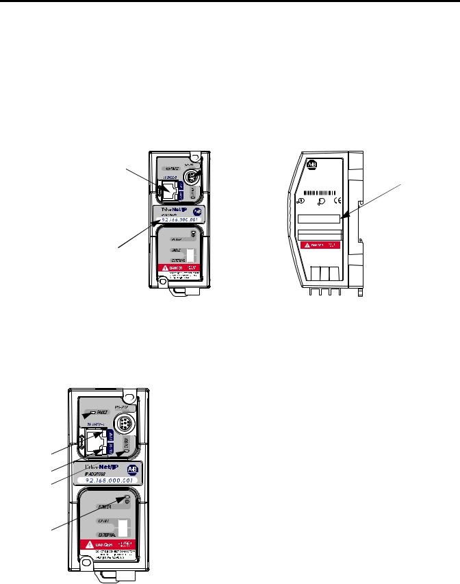
Hardware Features
Ethernet Port 
IP Address
Write-On Area
The ENI also supports an SMTP mail service that allows an existing controller to send e-mail messages to any destination connected to the network. The e-mail can be used to initiate the transmission of data or status information.
Product Drawing
RS-232 |
|
Mini-DIN Port |
ENI |
ETHERNET
INTERFACE MODULE
|
CAT |
|
SER FRN |
Ethernet Hardware |
|
1761-NET-ENI |
A 1.01 |
||
|
|
|||
|
WIN (21)1P6AA0BB Mfg. 1200 Fac. 1P |
Address |
||
|
LISTED IND.CONT.EQ. |
|
OPERATING |
|
R |
FOR HAZ. LOC. A196 |
C |
TEMPERATURE |
|
|
CODE T3C |
|
||
R
CLASS I, GROUPS A,B,C, AND D, DIV 2
ETHERNET ADDRESS
EXTERNAL POWER REQUIREMENTS
24 V dc +10/-15% AT 100 mA N.E.C. CLASS 2
USE EXTERNAL DC SOURCE
FOR CLASS I DIVISION 2
APPLICATIONS. SEE
INSTALLATION INSTRUCTIONS
MADE IN U.S.A.
24VDC |
DC NEUT |
CHS GND |
FAULT 
LINK 
Ethernet TX/RX
RS-232 TX/RX 
POWER 
LED Indicators
The ENI has five LED indicators:
LED |
Description |
Function |
Color |
|
|
|
|
TX/RX |
RS-232 data |
flashes when the RS-232 port is |
green |
|
transmission indicator |
transmitting or receiving data |
|
|
|
|
|
POWER |
module power |
lit when module is powered |
green |
|
|
|
|
LINK |
Ethernet link status |
lit when there is a valid physical |
green |
|
|
Ethernet connection |
|
|
|
|
|
TX/RX |
Ethernet data |
flashes when the Ethernet port is |
green |
|
transmission indicator |
transmitting or receiving data |
|
|
|
|
|
FAULT |
fault condition indicator |
lit when a fault condition is present |
red |
|
|
|
|
For more detailed information on LED operation, see Chapter 8, Troubleshooting.
Publication 1761-UM006A-EN-P - February 2001
Product Overview |
1-3 |
|
|
Default Settings
The ENI’s RS-232 port has the following default settings:
Table 1.1 RS-232 Settings
Setting |
Default |
Other Options |
|
|
|
|
|
Baud Rate |
Autobaud |
see table 4.7 |
|
|
|
|
|
Handshaking (hardware, software) |
none |
none |
|
|
|
|
|
Data Bits |
8 |
|
none |
|
|
|
|
Stop Bits |
1 |
|
none |
|
|
|
|
Parity |
none |
none |
|
|
|
|
|
Table 1.2 DF1 Settings |
|
|
|
|
|
|
|
Setting |
Default |
Other Options |
|
|
|
|
|
Duplicate Message Detection |
Enable |
none |
|
|
|
|
|
Error Detection |
CRC, BCC |
Auto-detect when |
|
|
|
|
Autobaud is true, |
|
|
|
otherwise CRC |
|
|
|
|
Embedded Response Operation |
Auto-Detect, for |
none |
|
|
reception only(1) |
|
|
DLE ACK Timeout |
1 second |
none |
|
|
|
|
|
DLE NAK Receive |
3 |
NAK retries |
none |
|
|
|
|
DLE ENQ for Response |
3 |
ENQs retries |
none |
|
|
|
|
DF1 Node Address |
Don’t Care |
|
|
|
|
|
|
(1) The ENI receives NAKs and ACKs, but does not generate them.
Publication 1761-UM006A-EN-P - February 2001

1-4 Product Overview
Operating Modes
Messaging
When the ENI is connected to a programmable controller (and connected to an Ethernet network), the controller can be accessed from other devices on Ethernet, or initiate communications to other Ethernet/IP devices.
Device Compatibility
The ENI also supports SMTP mail service, that allows a controller to send e-mail messages to any e-mail address on the network. The e-mail can be used to initiate the transmission of data or status information.
The ENI is compatible with the following devices and applications:
•All MicroLogix, SLC, and PLC-5 DF1 Full-Duplex capable controllers that have at least one RS-232 port
•Personal Computers using the RSLinx (V2.30.00 and higher) DF1 Full-Duplex Driver
•Other DF1 Full-Duplex compliant products that have at least one RS-232 port, for example, operator interface devices
•RSLinx (V2.30.00 and higher) Ethernet Driver
•CompactLogix
Publication 1761-UM006A-EN-P - February 2001
Product Overview |
1-5 |
|
|
Ethernet Networks
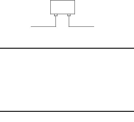
Basic Ethernet Topology
The ENI Ethernet connector conforms to ISO/IEC 8802-3 STD 802.3 and utilizes 10Base-T media. Connections are made directly from the ENI to an Ethernet switch. The network setup is simple and cost effective. Typical network topology is pictured below.
Ethernet
Switch
to PC Ethernet Card or other Ethernet Device
RJ45 connectors on both ends of cable (10Base-T)
to ENI
|
The ENI provides a 10Base-T, RJ45 Ethernet |
|
IMPORTANT |
||
connector which connects to standard Ethernet hubs |
||
|
||
|
||
|
and switches via an 8-wire twisted pair |
|
|
straight-through cable. To access other Ethernet |
|
|
mediums, use 10Base-T media converters or Ethernet |
|
|
switches that can be connected together via fiber, |
|
|
thin-wire, or thick-wire coaxial cables, or any other |
|
|
physical media commercially available with Ethernet |
|
|
switches. See page 2-7 for more cable information. |
|
|
|
|
The IP addresses in any of the examples in this |
|
IMPORTANT |
||
manual were arbitrarily assigned and should only be |
||
|
||
|
||
|
used on an isolated Ethernet network. Contact your |
|
|
system administrator for unique IP addresses if you |
|
|
are connecting your Ethernet devices to your |
|
|
employer’s Ethernet network. |
|
|
|
Using a Web Browser with the ENI
You can access information about the ENI via your web browser. Simply enter the ENI’s TCP/IP address into the address field of your browser.
Publication 1761-UM006A-EN-P - February 2001

1-6 Product Overview
Publication 1761-UM006A-EN-P - February 2001

Chapter 2
Installation and Wiring
European Communities (EC)
Directive Compliance
This chapter covers installation and wiring for the ENI. It is divided into the following sections:
•European Communities (EC) Directive Compliance
•Safety Considerations
•Mounting
•External Power Supply Wiring
•ENI Port Identification
•Ethernet Connections
•RS-232 Port Connections
This product has the CE mark. It is approved for installation within the European Union and EEA regions. It has been designed and tested to meet the following directives.
EMC Directive
This product is tested to meet the Council Directive 89/336/EC Electromagnetic Compatibility (EMC) by applying the following standards, in whole or in part, documented in a technical construction file:
•EN 50081-2 EMC — Generic Emission Standard, Part 2 — Industrial Environment
•EN 50082-2 EMC — Generic Immunity Standard, Part 2 — Industrial Environment
This product is intended for use in an industrial environment.
Low Voltage Directive
This product is tested to meet Council Directive 73/23/EEC Low Voltage, by applying the safety requirements of EN 61131-2 Programmable Controllers, Part 2 - Equipment Requirements and
Publication 1761-UM006A-EN-P - February 2001
2-2 Installation and Wiring
Safety Considerations
Tests. For specific information required by EN 61131-2, see the appropriate sections in this publication, as well as the Allen-Bradley publication Industrial Automation Wiring and Grounding Guidelines For Noise Immunity, publication 1770-4.1.
Open style devices must be provided with environmental and safety protection by proper mounting in enclosures designed for specific application conditions. See NEMA Standards publication 250 and IEC publication 529, as applicable, for explanations of the degrees of protection provided by different types of enclosure.
This equipment is suitable for use in Class I, Division 2, Groups A, B, C, D, or non-hazardous locations only. The following WARNING statement applies to use in hazardous locations.
WARNING
!
Explosion Hazard
•Substitution of components may impair suitability for Class I, Division 2.
•Do not replace components or disconnect equipment unless power has been switched off and the area is known to be non-hazardous.
•Do not connect or disconnect connectors or operate switches while circuit is live unless the area is known to be non-hazardous.
•This product must be installed in an enclosure. All cables connected to the product must remain in the enclosure or be protected by conduit or other means.
•The ENI must be operated from an external power source.
•All wiring must comply with N.E.C. article 501-4(b).
Use only the following communication cables and replacement connectors in Class I Division 2 Hazardous Locations.
Environment Classification |
Communication Cable and Connectors |
||
|
|
|
|
Class I, Division 2 Hazardous |
1761-CBL-PM02 Series C |
2707-NC8 Series B |
|
Environment |
|
|
|
1761-CBL-HM02 Series C |
2707-NC9 Series B |
||
|
|||
|
|
|
|
|
1761-CBL-AM00 Series C |
2707-NC10 Series B |
|
|
|
|
|
|
1761-CBL-AP00 Series C |
2707-NC11 Series B |
|
|
|
|
|
Publication 1761-UM006A-EN-P - February 2001
Installation and Wiring |
2-3 |
|
|
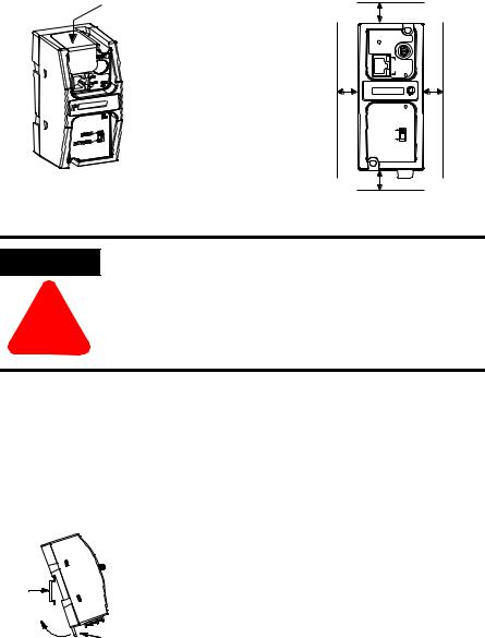
Mounting
The 1761-NET-ENI must be mounted in the vertical position, as shown. Horizontal mounting is not recommended due to thermal considerations. Allow 50 mm (2 in.) of space on all sides for adequate ventilation. See page A-1 for operating temperature specification.
protective debris strip |
top |
|
|
|
|
|
ETHERNET |
|
|
RS232 |
|
|
FAULT |
|
|
NET |
|
|
TX/RX TX/RX |
|
side |
IP |
side |
|
PWR |
|
|
CABLE |
|
|
EXTERNAL |
|
|
bottom |
|
ATTENTION
!
Do not remove the protective debris strip until after all the equipment in the panel is mounted and wiring is complete. Once wiring is complete, remove protective debris strip. Failure to remove strip before operating can cause overheating.
DIN Rail Mounting
Installation
DIN
Rail
Latch
1.Mount your DIN rail.
2.Snap the DIN rail latch into the closed position.
3.Hook the top slot over the DIN rail.
4.While pressing the unit against the rail, snap the unit into position.
Publication 1761-UM006A-EN-P - February 2001
2-4 Installation and Wiring
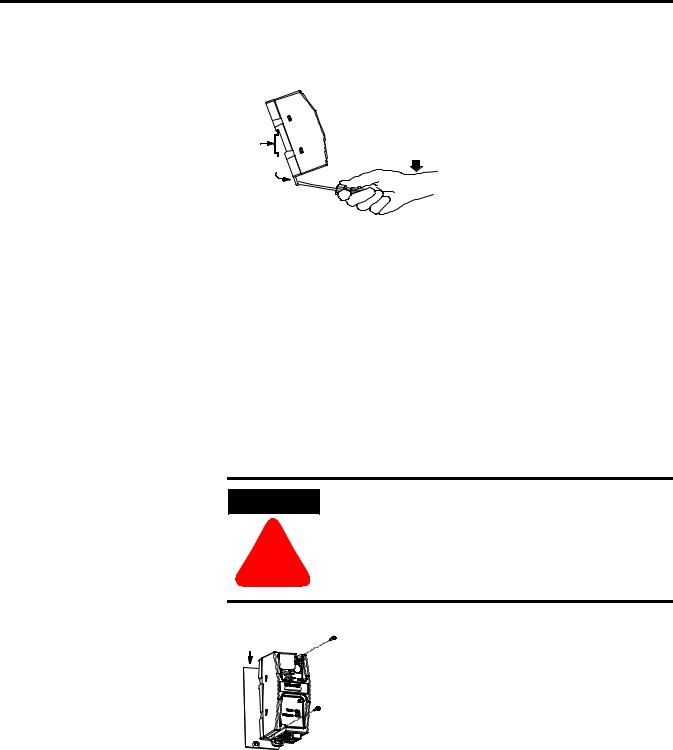
Removal
DIN
Side
Rail
View
1.Place a screwdriver in the DIN rail latch at the bottom of the unit.
2.Holding the unit, pry downward on the latch until the unit is released from the DIN rail.
Panel Mounting
Template
See Appendix A for panel mounting template.
Installation
ATTENTION
!
Be careful of metal chips when drilling mounting holes for your equipment within the enclosure or panel. Drilled fragments that fall into the equipment could cause damage. Do not drill holes above mounted equipment if the protective debris strip has been removed.
Mounting
Template
1.Remove the mounting template from the back of this document.
2.Secure the template to the mounting surface.
3.Drill holes through the template.
4.Remove the mounting template.
5.Mount the unit.
Publication 1761-UM006A-EN-P - February 2001
Installation and Wiring |
2-5 |
|
|
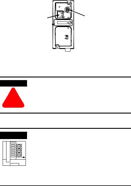
ENI Port Identification
ETHERNET
RS232
FAULT
NET
TX/RX TX/RX
Ethernet Port (ENI Port 1)
IP
Write-on area for 
PWR
Ethernet IP address
CABLE
EXTERNAL
RS-232 Mini-DIN (ENI Port 2)
External Power Supply
Wiring
WARNING
!
EXPLOSION HAZARD - In Class I Division 2 applications, an external, Class 2 power supply must be used. The DC Power Source selector switch on the ENI must be set to EXTERNAL before connecting the power supply to the ENI.
IMPORTANT
24 VDC
DC
NEUT
CHS
GND
Bottom View
•In non-hazardous locations, external power is not required. Some devices (such as a MicroLogix controller) provide power to the ENI via a cable connected to ENI port 2. Be sure to set the DC power source selector switch to match your particular configuration, CABLE or EXTERNAL.
•Always connect the CHS GND (chassis ground) terminal to the nearest earth ground. This connection must be made whether or not an external 24V dc supply is used.
Publication 1761-UM006A-EN-P - February 2001

2-6 Installation and Wiring
Ethernet Connections
Ethernet 8-Pin 10Base-T Connector (Port 1)
The Ethernet connector is an RJ45, 10Base-T connector. The pin-out for the connector is shown below:
Pin |
Pin Name |
|
|
1 |
Tx+ |
|
|
2 |
Tx- |
|
|
3 |
Rx+ |
|
|
4 |
not used by 10Base-T |
|
|
5 |
not used by 10Base-T |
|
|
6 |
Rx- |
|
|
7 |
not used by 10Base-T |
|
|
8 |
not used by 10Base-T |
|
|
When to use straight-through and cross-over cable:
•ENI Ethernet port to 10Base-T Ethernet switch cables utilize a straight-through pin-out (1-1, 2-2, 3-3, 6-6).
•Direct point-to-point 10Base-T cables connecting the ENI Ethernet port directly to another ENI Ethernet port (or a computer 10Base-T port) require a cross-over pin-out (1-3, 2-6, 3-1, 6-2).
Publication 1761-UM006A-EN-P - February 2001
Installation and Wiring |
2-7 |
|
|
Ethernet Cables
Shielded and non-shielded twisted-pair 10Base-T cables with RJ45 connectors are supported. The maximum cable length between an ENI Ethernet port and a 10Base-T port on an Ethernet switch (without repeaters or fiber) is 100 meters (323 feet). However, in an industrial application, the cable length should be kept to a minimum.
With media converters or Ethernet switches, you can also connect to the following media:
•fiber optic
•broadband
•thick-wire coaxial cable (10Base-5)
•thin-wire coaxial cable (10Base-2)
Maintain ENI Connections
The unshielded twisted pair (UTP) patch cable on a switch should be labeled and treated as dedicated. Be careful when moving any cables, as port identity may be effected. If you are using a switch and must move the ENI to a new port for any reason, power-cycle the ENI. The power cycle forces a new Address Resolution Protocol (ARP) sequence which should immediately associate the ENI’s IP address with the port it is connected to.
You should also discourage any field personal from treating the ports of a switch as “all the same”. This helps to prevent any problems with network communications being effected by moving cables.
Publication 1761-UM006A-EN-P - February 2001

2-8 Installation and Wiring
RS-232 Port Connections |
RS-232 Connector |
|
|
|
7 |
|
6 |
8 |
|
8-pin mini-DIN |
3 |
|
5 |
|
|
4 |
|
2 |
1 |
|
Table 2.1 RS-232 Connector Pin Assignments
Pin |
Port 2 |
124V dc
2ground (GND)
3no connection
4ENI input data, RxD
5no connection
6no connection
7ENI output data, TxD
8ground (GND)
RS-232 Cables
Port 2 of the ENI is an 8-pin mini-DIN RS-232 port that provides connection to DF1 compatible RS-232 devices. The table below describes the RS-232 compatible cables.
ENI Connected to: |
Catalog Number |
Use Cable |
|
|
|
MicroLogix (all series) |
|
Mini DIN to Mini DIN |
|
1761-CBL-AM00 |
45 cm (17.7 in) |
|
1761-CBL-HM02 |
2m (6.5 ft.) |
|
|
|
SLC 5/03, SLC 5/04, or |
|
Mini DIN to D-Shell |
SLC 5/05 Channel 0 |
1761-CBL-AP00 |
45 cm (17.7 in) |
|
1761-CBL-PM02 |
2m (6.5 ft.) |
|
|
|
PLC-5 |
|
Mini DIN to D-Shell |
|
1761-CBL-AP00 |
45 cm (17.7 in) |
|
1761-CBL-PM02 |
2m (6.5 ft.) |
|
|
|
See page 2-2 for the list of cables that can be used in a hazardous environment.
Publication 1761-UM006A-EN-P - February 2001

Chapter 3
Operation Overview
Allocation of Ethernet
Connections
Operation
This chapter describes ENI operation. The following information is included:
•Operation Overview
•Allocation of Ethernet Connections
•ENI Functional Overview
•Program Upload/Download and On-Line Sessions
Ethernet is the protocol used to transport TCP/IP messages. On top of TCP, Ethernet/IP is the open protocol used by the ENI. Ethernet/IP allows devices to exchange information (data); or to upload, download, and edit logic programs over Ethernet.
To communicate between devices, Ethernet/IP uses a “connection” model. Connections are dedicated paths across Ethernet between devices.
The ENI supports a maximum of 6 connections, allowing simultaneous communication with up to 6 other devices or applications. The connections are dedicated as follows:
Number of Connections |
Dedicated to: |
|
|
2 |
outgoing messages |
|
|
2 |
incoming messages |
|
|
2 |
either incoming or outgoing messages |
|
|
TIP |
For peer connections, no more than one connection |
|
per destination node is established. If multiple MSG |
||
|
||
|
||
|
instructions use the same destination node, they use |
|
|
the same connection. |
Publication 1761-UM006A-EN-P - February 2001

3-2 Operation
ENI Functional Overview |
The ENI provides Ethernet/IP connectivity for RS-232 devices that use |
|||
|
|
DF1 full-duplex protocol. DF1 full-duplex is an open, point-to-point |
||
|
|
protocol used in any Allen-Bradley controller with an RS-232 port, and |
||
|
|
in many other devices. DF1 full-duplex supports up to 256 nodes. The |
||
|
|
ENI uses these nodes for different functions. |
|
|
|
|
The ENI uses a memory (node) map to provide access to the different |
||
|
|
functions you can perform. Each function uses a different group of |
||
|
|
node addresses. The following table illustrates the ENI functions by |
||
|
|
groups of node numbers: |
|
|
|
|
|
|
|
ENI Function |
Node Group |
Node Function |
Valid Data Type |
For More |
|
|
|
|
Information |
|
|
|
|
|
Message Routing |
Node 100 to 149 |
Configure Route Address |
Integer |
see chapter 5 |
|
|
|
|
|
|
Node 0 to 49 |
Route DF1 MSG to IP at Configured Route |
Integer |
see chapter 5 |
|
|
Address |
|
|
|
|
|
|
|
Node 150 to 199 |
Configure SMTP e-mail address |
String |
see chapter 6 |
|
|
|
|
|
|
|
Node 50 to 99 |
Send e-mail message to configured SMTP |
String |
see chapter 6 |
|
|
e-mail address |
|
|
|
|
|
|
|
ENI Configuration |
Node 248 to 254 |
ENI Configuration Registers |
Integer or String |
see chapter 4 |
|
|
|
depending on parameter |
|
|
|
|
|
|
Program Upload/Download
and On-Line Sessions
The ENI allows you to connect from your PC to controllers over Ethernet. The following procedure can be used when the computer has a connection directly onto Ethernet (PCI card, PCMCIA interface, built in TCP/IP port, etc.) and the ENI is plugged into the computer’s RS-232 (COMM) port.
RSLinx on Ethernet (PC Connected to Ethernet)
|
You must use RSLinx version 2.30.00 or newer to |
|
IMPORTANT |
||
connect with the 1761-NET-ENI. |
||
|
||
|
||
|
|
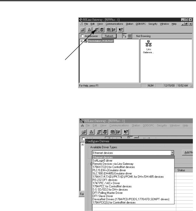
Follow these steps to configure RSLinx for Ethernet operation.
1. Open RSLinx and open the driver configuration dialog.
Publication 1761-UM006A-EN-P - February 2001
Operation 3-3
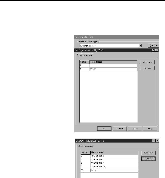
2.The “Configure Dialog” will open, select Ethernet devices from the available drivers, and then click “OK” to load the driver into RSLinx.
Once the Ethernet driver is loaded, either highlight and select “Configure” or simply double click on the Ethernet driver.
Publication 1761-UM006A-EN-P - February 2001
3-4 Operation
At that point the station mapping screen will appear as illustrated here. Double click on the row below “Host Name”, and enter the TCP/IP addresses that match the devices on your network that you will need access to.
When you are done entering the stations, click OK to close the station mapping window.
Publication 1761-UM006A-EN-P - February 2001
Operation 3-5
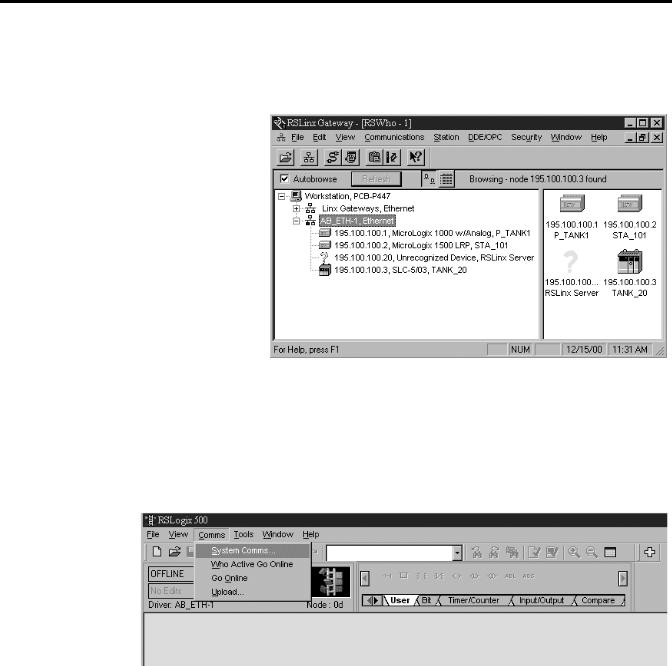
3.Open the AB_ETH-1 tree on your computer, autobrowse should be running and any active device that you have configured should be shown on the screen as illustrated below.
RSLogix 500
1. Open RSLogix 500 and select “Comms”
Publication 1761-UM006A-EN-P - February 2001
3-6 Operation
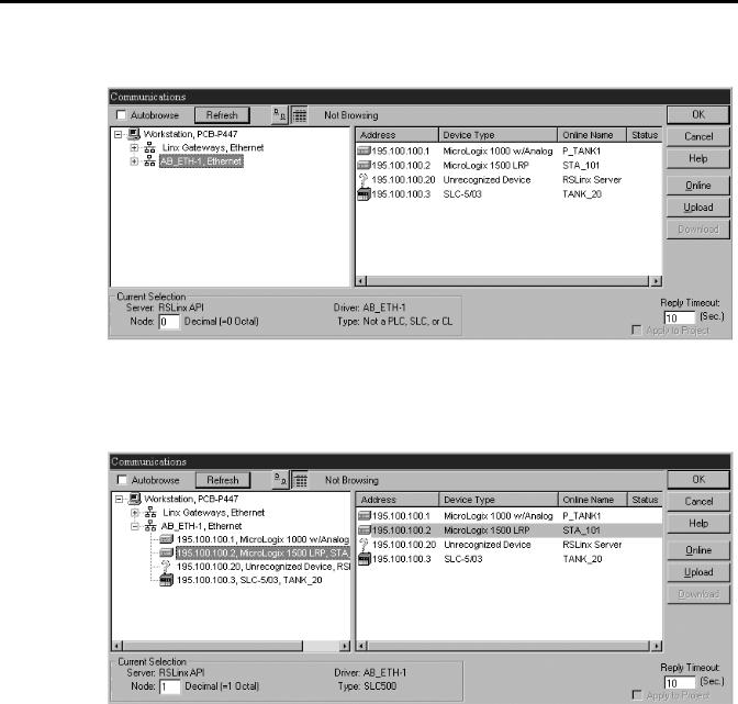
2. Select “AB_ETH-1, Ethernet.
3.Either expand the tree (select the + in the box, or select the device from the table to the right. From this point, you can then either go online or perform an upload or download.
Publication 1761-UM006A-EN-P - February 2001

Chapter 4
ENI Configuration (Node 248 to 254)
Configuration Methods
This chapter describes configuration methods and parameters. It is arranged as follows:
•Configuration Methods
•ENI Configuration Utility
•Controller Messaging
•Configuring ENI Data Parameters
•Configuring ENI String Parameters
•ENI Configuration Parameters
The ENI’s IP information can be entered using either:
•the ENI Configuration Utility
•a write message from the Allen-Bradley controller to node address 250
•the BOOTP Utility over Ethernet (BOOTP configuration is described in Appendix B of this manual)
ENI Configuration Utility |
The ENI Configuration Utility is free software designed for configuring |
||
|
the ENI. It is available from http://www.ab.com/micrologix. |
||
|
|
|
When using the ENI Configuration Utility, be |
|
|
TIP |
|
|
|
sure to use a 1761-CBL-PM02 Series C cable |
|
|
|
|
|
|
|
|
|
|
|
|
between the ENI and the computer. |
Publication 1761-UM006A-EN-P - February 2001
4-2 ENI Configuration (Node 248 to 254)
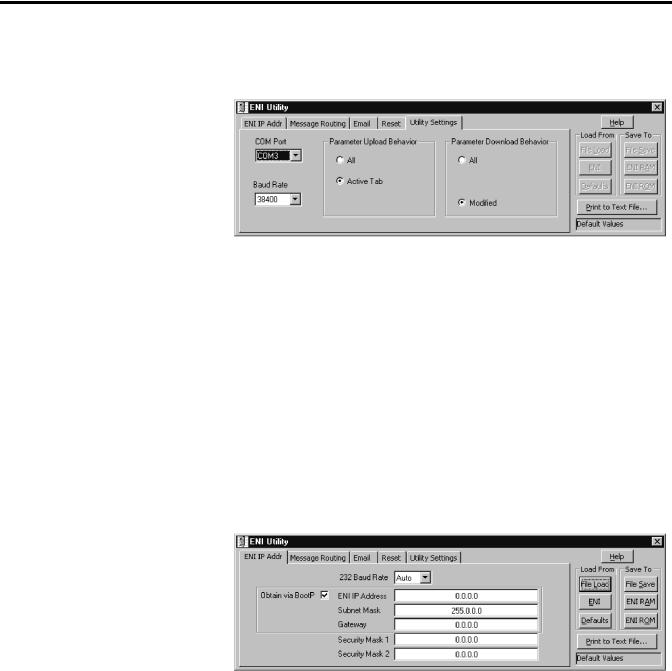
COM Port Settings
Use the Utility Settings screen to set the following:
•COM Port - The PC’s RS-232 port that the communications cable is plugged into.
•Baud Rate - Select a baud rate or choose Autobaud. See page 4-15 for more information.
•Parameter Upload Behavior and Parameter Download Behavior - This setting controls which parameters will be saved or loaded when you use the Load From or Save To buttons.
RS-232 Baud Rate and TCP/IP Parameters
Use the ENI IP Addr screen to set the following:
•232 Baud Rate - Select a baud rate or choose Autobaud. See page 4-15 for more information.
•TCP/IP Parameters - See page 4-12 for more information on valid addresses.
Publication 1761-UM006A-EN-P - February 2001
Loading...