


 Loading...
GE Fanuc Automation
Programmable Control Products
TCP/IP Ethernet Communications for the Series 90t-30 PLC
User's Manual
GFK-1084B |
August, 1997 |

GFL±002
Warnings, Cautions, and Notes as Used in this Publication
Warning
Warning notices are used in this publication to emphasize that hazardous voltages, currents, temperatures, or other conditions that could cause personal injury exist in this equipment or may be associated with its use.
In situations where inattention could cause either personal injury or damage to equipment, a Warning notice is used.
Caution
Caution notices are used where equipment might be damaged if care is not taken.
Note
Notes merely call attention to information that is especially significant to understanding and operating the equipment.
This document is based on information available at the time of its publication. While efforts have been made to be accurate, the information contained herein does not purport to cover all details or variations in hardware or software, nor to provide for every possible contingency in connection with installation, operation, or maintenance. Features may be described herein which are not present in all hardware and software systems. GE Fanuc Automation assumes no obligation of notice to holders of this document with respect to changes subsequently made.
GE Fanuc Automation makes no representation or warranty, expressed, implied, or statutory with respect to, and assumes no responsibility for the accuracy, completeness, sufficiency, or usefulness of the information contained herein. No warranties of merchantability or fitness for purpose shall apply.
The following are trademarks of GE FanucAutomationNorthAmerica,Inc.
Alarm Master |
Field Control |
Modelmaster |
Series One |
CIMPLICITY |
GEnet |
PowerMotion |
SeriesSix |
CIMPLICITYControl |
Genius |
ProLoop |
Series Three |
CIMPLICITY PowerTRAC |
Genius PowerTRAC |
PROMACRO |
VuMaster |
CIMPLICITY 90-ADS |
Helpmate |
Series Five |
Workmaster |
CIMSTAR |
Logicmaster |
Series 90 |
|
Copyright 1995-1997 GE Fanuc Automation North America, Inc.
All Rights Reserved

Preface
Content of This Manual
Chapter 1. Introduction: Discusses the TCP/IP Ethernet Interface, its communications capabilities, and generally how to get your system running. Also included is a quick guide to the manual.
Chapter 2. Installing the TCP/IP Ethernet Interface: Describes the basic features of theTCP/IPEthernet Interface, the installation and power-up of the Interface, and a procedure for the initial checkout of the Interface on your Ethernet cable.
Chapter 3. Programming Communications Requests: Describes the ladder programming necessary for communications between PLCs.
Chapter 4. Troubleshooting: Describes troubleshooting and problem isolation for the Ethernet Interface.
Appendix A. Glossary of Terms
Appendix B. Communications Port Characteristics
Appendix C. Advanced Information About IP and MAC Addresses
Appendix D. Sample Ladder Program
Appendix E. PC Software loader
Related Publications
GFK-1186 TCP/IP Ethernet Communications for the Series 90 PLC Station Manager Manual
GFK-0356 Series 90t-30 Programmable Controller Installation Manual
GFK-0466 Logicmaster 90t Series 90t-30/20/Micro Programming Software User's Manual
GFK-1295 Using CIMPLICITYRControl
GFK-0467 Series 90t-30/20/Micro Programming Software Reference Manual
GFK-0870 Host Communications Toolkit for C/C++ Applications User's Manual
GFK-1063 Host Communications Toolkit for Visual Basic Applications User's Manual
GFK-1026 Host Communications Drivers for Microsoft Windows User's Manual
We Welcome Your Comments and Suggestions
At GE Fanuc Automation, we strive to produce quality technical documentation. After you have used this manual, please take a few moments to complete and return the Reader's Comment Card located on the next page.
GFK-1084B |
iii |

" "!
" )-+ |
'-+( .-#(' |
1 |
|
*' 5*'3/'5 /5'3(#%' |
; |
|
08 50 #,' 5*' :45'. !03, |
;4 |
|
6+%, 6+&' 50 5*' #/6#- |
; |
" )-+ |
',-%%#'! -" -" +'- '-+ |
1 |
|
|
5*'3/'5 /5'3(#%' #3&8#3' 7'37+'8 |
|
; |
|
0#3& /&+%#5034 |
|
;3 |
|
'45#35 6550/ |
|
;3 |
|
'3+#- 0354 |
4 |
;4 |
|
3#/4%'+7'3 035 |
|
; |
|
'(#6-5 5#5+0/ &&3'44 #$'- |
|
; |
|
'3+#- 6.$'3 #$'- |
|
; |
|
+( .+ : ',-%%#'! -" -" +'- '-+ #' -" |
16 |
|
|
26+1.'/5 '26+3'& 50 '3(03. 5*' /45#--#5+0/ 30%'&63'4 |
; |
|
|
5*'3/'5 /5'3(#%' /45#--#5+0/ |
; |
|
|
+( .+ : (' #!.+#'! -" -" +'- '-+ /#-" |
|
|
|
(!# & ,-+ 1 (' #!.+-#(' ( -/ + |
1 |
|
|
+( .+ : (' #!.+#'! -" -" +'- '-+ .,#'! |
|
|
|
('-+(% |
1 |
|
|
+( .+ : +# 0#'! +() + (/ +1 ) ( -" -" +'- '-+ |
1 7 |
|
|
08'3+/);61 5*' 5*'3/'5 /5'3(#%' |
; 7 |
|
|
30$-'.4 63+/) 08'3;61 |
; 7 |
|
|
+( .+ : #'!#'! -" +'- '-+ , (' -" -/(+$ |
1 |
|
|
+/)+/) 5*' /5'3(#%' (30. # " *045 03 # 6//+/) 0(58#3' |
; |
|
" )-+ |
+(!+ &'! (&&.'#-#(', *. ,-, |
1 |
|
|
-#(' : " (&&.'#-#(', *. ,- |
1 |
|
|
536%563' 0( 5*' 0..6/+%#5+0/4 '26'45 |
3; |
|
|
6/%5+0/ -0%, |
3;3 |
|
|
0..#/& -0%, |
3;3 |
|
|
*#//'- 0..#/&4 |
3;3 |
|
|
5#564 #5# 4 |
3;4 |
|
|
*' 0)+% 30)3#. 0/530--+/) 9'%65+0/ 0( 5*' |
|
|
|
6/%5+0/ -0%, |
3;4 |
|
|
1'3#5+0/ 0( 5*' 0..6/+%#5+0/4 '26'45 |
3; |
|
% |
E" " # " ! ! ! # % A# #!" 99 |
$ |

" "!
|
Section 2: The COMMR Q Function Block and Command Block |
3.6 |
|||||
|
The COMMREQ Function Block |
3;6 |
|||||
|
The COMMREQ Command Block |
|
3;7 |
||||
|
Section 3: Channel Commands |
|
3.9 |
||||
|
Establishing a Channel |
3;9 |
|||||
|
Aborting and Re;tasking a Channel |
3;9 |
|||||
|
Retrieving Detailed Status on the Channel |
|
3;10 |
||||
|
Specif:ing a Network Address |
|
3;10 |
||||
|
Establish Read Channel 2003 |
|
3;11 |
||||
|
Establish Write Channel 2004 |
|
|
3;18 |
|||
|
Send nformation Report 2010 |
|
|
3;24 |
|||
|
Abort Channel 2001 |
|
3;29 |
||||
|
Retrieve Detailed Channel Status 2002 |
|
3;30 |
||||
|
Section 4: Status Data |
|
3.32 |
||||
|
T:pes of Status Data |
|
3;32 |
||||
|
Description of the Status Data |
3;33 |
|||||
|
OK Output of the COMMREQ Function Block |
3;33 |
|||||
|
FT Output of the COMMREQ Function Block |
|
3;33 |
||||
|
Status Bits |
5 |
3;33 |
||||
|
Communications Status Words |
|
|
3;36 |
|||
|
Minor Error Codes |
3;38 |
|||||
|
Section 5: Controlling Communications in the Ladder Program |
3.41 |
|||||
|
Essential Elements of the Ladder Program |
3;41 |
|||||
|
Troubleshooting Your Ladder Program |
3;44 |
|||||
|
Monitoring the Communications Channel |
3;45 |
|||||
|
Sequencing Communications Requests |
3;46 |
|||||
|
Data Transfers with One Repetition |
3;46 |
|||||
Chapter 4 |
Troubleshooting |
4.1 |
|||||
|
Diagnostic Tools Available for Troubleshooting |
4;1 |
|||||
|
What to do if :ou Cannot Solve the Problem |
4;2 |
|||||
|
PLC Fault Table 5 |
4;2 |
|||||
Appendix A |
Glossary |
A.1 |
|||||
|
Commonl: Used Acron:ms and Abbreviations |
|
A;1 |
||||
|
Glossar: of Terms |
A;2 |
|||||
% |
E" " # " ! ! ! # % A# #!" 99 |
$ |

" "!
Appendix B |
Communications Ports Characteristics |
B%1 |
|
Station Manager Port |
B22 |
|
Station Manager Port Settings |
B22 |
|
Station Manager Port Pinouts |
B22 |
|
Station Manager Port Cable |
B23 |
|
Software Loader Port Serial Port 2 |
B24 |
|
Software Loader Port Pinouts |
B24 |
|
Part Numbers for GE Fanuc Cables and Converters |
B25 |
|
Software Loader Port Cable |
B25 |
|
The AAUI Port for the Ethernet Interface |
B26 |
|
Ethernet AAUI Port Pinouts |
B26 |
|
Transceiver Configurations |
B27 |
|
Display Terminal Settings |
B210 |
Appendix C |
Advanced Information About IP and MAC Addresses |
C%1 |
||
|
IP Addresses 5 |
C21 |
||
|
Gateways |
5 |
C22 |
|
|
Subnets 5 |
C23 |
||
|
MAC Addresses 5 |
C24 |
||
Appendix D |
Sample Ladder Programs |
D%1 |
||
Appendix E |
PC Software Loader |
E%1 |
||
Appendix F |
Naming Architecture |
F%1 |
||
|
Name Assignment |
F21 |
||
|
Name Resolution |
F22 |
||
|
Local Table Name Resolution |
F22 |
||
|
DDP Name Resolution |
|
F22 |
|
|
DNS Name Resolution |
|
F22 |
|
|
Name Usage 5 |
F22 |
||
% |
E" " # " ! ! ! # % A# #!" 99 |
$ |
Contents |
||
|
|
|
Figure 1-1. Ethernet Communications System . . . . . . . . . . . . . . . . . . . . . . . . . . . . . . . . . . . . . . . . . . . . . . |
1-1 |
|
Figure 1-2. The Main Tasks for Installing the Ethernet Interface . . . . . . . . . . . . . . . . . . . . . . . . . . . . . . . |
1-4 |
|
Figure 2-1. Ethernet Interface . . . . . . . . . . . . . . . . . . . . . . . . . . . . . . . . . . . . . . . . . . . . . . . . . . . . . . . . . . . . |
2-2 |
|
Figure 2-2. States of the Ethernet Interface . . . . . . . . . . . . . . . . . . . . . . . . . . . . . . . . . . . . . . . . . . . . . . . . . |
2-18 |
|
Figure 3-1. Elements of the Communications Request . . . . . . . . . . . . . . . . . . . . . . . . . . . . . . . . . . . . . . . |
3-2 |
|
Figure 3-2. Operation of the Communications Request for an Establish Read ChannelCommand . . |
3-5 |
|
Figure 3-3. Format of the COMMREQ Status Word (CRS Word) . . . . . . . . . . . . . . . . . . . . . . . . . . . . . . |
3-36 |
|
Figure 3-4. Format of the Detailed Channel Status Words (DCS Words) . . . . . . . . . . . . . . . . . . . . . . . . |
3-36 |
|
Figure B-1. Serial Cable (IC693CBL316A) to Connect the Personal Computer to the |
|
|
Station Manager Port . . . . . . . . . . . . . . . . . . . . . . . . . . . . . . . . . . . . . . . . . . . . . . . . . . . . . . . . . |
B-3 |
|
Figure B-2. Software Loader Cable Assembly (IC690ACC901) . . . . . . . . . . . . . . . . . . . . . . . . . . . . . . . . . |
B-5 |
|
Figure B-3. 10Base2 Transceiver Configuration with Detachable Transceiver Cable (Available as |
|
|
GE Fanuc Part Number IC649AEA101 . . . . . . . . . . . . . . . . . . . . . . . . . . . . . . . . . . . . . . . . . . . |
B-7 |
|
Figure B-4. 10Base2 Transceiver Configuration with Built-in Transceiver Cable . . . . . . . . . . . . . . . . . . |
B-8 |
|
Figure B-5. 10Base2 Transceiver Configuration using BNC ªTº Connector . . . . . . . . . . . . . . . . . . . . . . |
B-8 |
|
Figure B-6. 10BaseT Transceiver Configuration . . . . . . . . . . . . . . . . . . . . . . . . . . . . . . . . . . . . . . . . . . . . . |
B-9 |
|
Figure B-7. AAUI to AUI Adapter. Can be used to connect to 10Base5 (shown above) or 10BaseF . . |
B-9 |
|
Figure C-1. IP Address Format for Network Classes A, B, C . . . . . . . . . . . . . . . . . . . . . . . . . . . . . . . . . . . |
C-1 |
|
Figure C-2. Connecting Two Networks with a Gateway . . . . . . . . . . . . . . . . . . . . . . . . . . . . . . . . . . . . . |
C-2 |
|
Figure C-3. Network Configuration Using a Subnet Mask . . . . . . . . . . . . . . . . . . . . . . . . . . . . . . . . . . . . |
C-3 |
|
Figure E-1. Software Loader Cable Assembly (IC690ACC901) . . . . . . . . . . . . . . . . . . . . . . . . . . . . . . . . . |
E-1 |
|
GFK-1084B |
TCP/IP Ethernet Communications User's Manual - August 1997 |
viii |
|
|
|
Contents |
|
|
|
|
||
Table 2-1. Problems During Power-Up . . . . . . . . . . . . . . . . . . . . . . . . . . . . . . . . . . . . . . . . . . . . . . . . . . . |
. . 2-19 |
|
||
Table 3-1. Time Unit ValuesforRead/Write Repetition Period . . . . . . . . . . . . . . . . . . . . . . . . . . . . . . . . |
. 3-12 |
|
||
Table 3-2. Series 90 PLC Memory Types . . . . . . . . . . . . . . . . . . . . . . . . . . . . . . . . . . . . . . . . . . . . . . . . . . |
. 3-13 |
|
||
Table 3-3. Status Bits (LIS Bits and Channel Status Bits) . . . . . . . . . . . . . . . . . . . . . . . . . . . . . . . . . . . . . |
. 3-34 |
|
||
Table 3-4. Major Error Codes . . . . . . . . . . . . . . . . . . . . . . . . . . . . . . . . . . . . . . . . . . . . . . . . . . . . . . . . . . . . |
. 3-37 |
|
||
Table 3-5. Minor Error Codes for Major Error Codes 05H (at Remote Server PLC) and |
|
|
||
|
|
85H (at Client PLC) . . . . . . . . . . . . . . . . . . . . . . . . . . . . . . . . . . . . . . . . . . . . . . . . . . . . . . . . . . |
. 3-38 |
|
Table 3-5. Minor Error Codes for Major Error Codes 5H and 85H (Continued) . . . . . . . . . . . . . . . . . |
. 3-39 |
|
||
Table 3-6. |
Minor Error Codes for Major Error Code 11H (at Remote Server PLC) . . . . . . . . . . . . . . . |
. 3-39 |
|
|
Table 3-7. |
Minor Error Codes for Major Error Code 90H (at Client PLC) . . . . . . . . . . . . . . . . . . . . . . . |
. 3-40 |
|
|
Table 4-1. |
PLC Fault Table Descriptions . . . . . . . . . . . . . . . . . . . . . . . . . . . . . . . . . . . . . . . . . . . . . . . . . . . |
. 4-3 |
|
|
Table 4-1. |
PLC Fault Table Descriptions (Continued) . . . . . . . . . . . . . . . . . . . . . . . . . . . . . . . . . . . . . . . . |
. 4-4 |
|
|
Table B-1. Station Manager Port Pinouts . . . . . . . . . . . . . . . . . . . . . . . . . . . . . . . . . . . . . . . . . . . . . . . . . . |
. B-2 |
|||
Table B-2. |
Serial Cable (IC693CBL316A) Connector Pinouts . . . . . . . . . . . . . . . . . . . . . . . . . . . . . . . . . |
. B-3 |
||
Table B-3. |
Software Loader Port Pinout . . . . . . . . . . . . . . . . . . . . . . . . . . . . . . . . . . . . . . . . . . . . . . . . . . . |
. B-4 |
||
Table B-4. |
Cables for Connecting the Software Loader Port to the RS-232 Port on Your PC . . . . . . . |
. B-5 |
||
Table B-5. |
Pinouts of the AAUI Port . . . . . . . . . . . . . . . . . . . . . . . . . . . . . . . . . . . . . . . . . . . . . . . . . . . . . . |
. B-6 |
||
GFK-1084B |
TCP/IP Ethernet Communications User's Manual - August 1997 |
ix |
Chapter Introduction
1
This manual describes the Ethernet Interface (IC693CMM321) for the Series 90-30 PLC.
This chapter provides an overview of the Ethernet Interface and covers the following topics.
HThe Ethernet Interface,
HHow to Make the System Work,
HQuick Guide to the Manual.
The Ethernet Interface
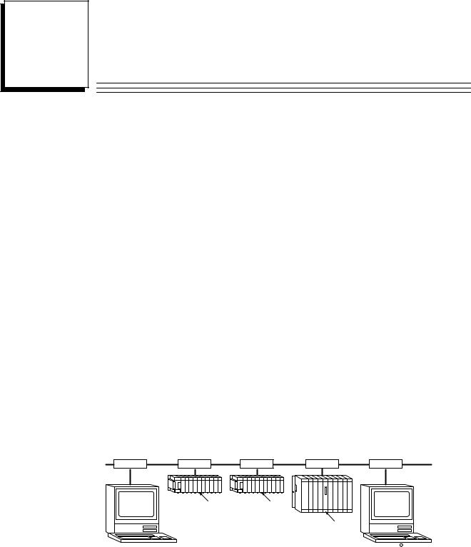
The Ethernet Interface enables the Series 90-30 PLC to communicate with other Series 90-30 PLCs, with Series 90-70 PLCs, with Logicmaster 90-30 TCP/IP Ethernet (IC641SWP313), with CIMPLICITYR Control (IC641CTL9xx) and with applications developed using the Host Communications Toolkit (IC641SWP05x). GE Fanuc offers the
Host Communications Toolkit separately from the Ethernet Interface.
The Ethernet Interface for the Series 90-30 PLC has ªclient/serverºcapability. As a ªclientº it can initiate communications with other Series 90 PLCs containing Ethernet Interfaces. This is done from the PLC ladder program using the COMMREQ function. As a ªserverº it responds to requests from other devices such as Logicmaster 90-30 TCP/IP Ethernet, a Host computer running a Host Communications Toolkit application, or another Series 90 PLC acting as a ªclientº. No PLC programming is required for server operation.
Figure 1-1 shows the Series 90-30 PLC in a basic Ethernet Communications System.
Ethernet |
|
|
|
|
|
|
a45694 |
Cable |
Transceiver |
Transceiver |
Transceiver |
||||
Transceiver |
Transceiver |
||||||
Network |
|
|
|
|
|
|
Network |
Connection |
|
|
|
|
|
|
Connection |
Series 90±30 |
Ethernet |
Series 90±30 |
Ethernet |
|
|
|
|
|
PLC |
PLC |
|
|
|
||
|
|
Interface |
|
Interface |
|
|
|
|
|
|
|
|
Series 90±70 |
Ethernet |
|
|
|
|
|
|
PLC |
|
|
|
|
|
|
|
|
Interface |
|
Host Computer or |
|
|
|
|
|
|
CIMPLICITY R Control or |
Control Device Running a |
|
|
|
|
|
|
Logicmaster 90 TCP/IP |
Host Communications |
|
|
|
|
|
|
Ethernet running on a PC |
Toolkit Application |
|
|
|
|
|
|
|
Figure 1-1. Ethernet Communications System
GFK-1084B |
1-1 |

1 |
Capabilities of the Ethernet Interface
The Ethernet Interface brings to your PLC a great deal of capability. It will allow you to:
HBecome operational quickly. The Ethernet Interface is made operational with very little effort. You need only install the Interface in the baseplate and, use the Logicmaster configuration package or CIMPLICITY Control to store basic configuration information to the module to make the basic server capability functional. Client capability, that is, the capability to initiate communications, can be added using the COMMREQ function in the ladder program.
HDirectly attach your PLC to an Ethernet network. The Ethernet Interface allows you to directly attach the Series 90-30 PLC to an Ethernet LAN via a user-supplied transceiver and AAUI cable, and to communicate with host computers and other Series 90 PLCs on the local network. All Series 90-30 models and all rack styles are supported.
HTransfer data between PLCs. The Ethernet Interface provides client capability, the capability to initiate communications to other Series 90 Ethernet Interfaces, using COMMREQ functions in the ladder program.
HAccess data using a Host computer. Computer applications which use the GE Fanuc Host Communications Toolkit can access data within the Series 90-30 PLC through the server capability of the Ethernet Interface. Supported computer operating systems include Windowsr, Windows NTr, HP-UX 9000, DEC VAX/VMSt, and DEC AlphaAXP/VMSt.
HCommunicate simultaneously to multiple devices. The multiplexing capabilities of the Ethernet Interface, along with Ethernet network's high capacity, allow the PLC to communicate with several other devices at the same time.
HMaintain compatibility with other GE Fanuc devices, as well as with devices from other vendors. The GE Fanuc Series 90-30 PLC with TCP/IP Ethernet Interface is compatible with the Series 90-70 PLC with TCP/IP Ethernet Interface.
It is also compatible with GE Fanuc Logicmaster 90-30 TCP/IP Ethernet, CIMPLICITY Control and GE Fanuc HCT Ethernet products available on DEC, HP, IBM, and other computer platforms runningTCP/IP.
HDiagnose and maintain your system, using diagnostic and station management tools.
You can find problems before they become serious. In the event that communications software upgrades are needed, you can use a built-in serial port to download the software to the Interface.
HIndirectly attach to other Local Area Networks and/or wide area networks via third party IP routers. When configured to use an IP gateway (router), the Ethernet Interface can communicate with remote PLCs and other nodes reachable through the router.
HCommunicate with remote computers via Serial Line Internet Protocol (SLIP) using modems and/or serial lines. Using third party SLIP software, a remote host computer can be attanched to a TCP/IP network.
tDEC, VAX,AlphaAXP, and VMS are trademarks of Digital Equipment Corporation. rWindows and Windows NT are registered trademarks of Microsoft Corporation.
1-2 |
TCP/IPEthernetCommunicationsUser's Manual ± August1997 |
GFK-1084B |
1 |
Attachment of the Ethernet Interface to the LAN
The AAUI port provides the electrical and mechanical interface to the user-provided Ethernet transceiver cable, which connects the AAUI port to an external user-provided transceiver. (The transceiver cable may be separate or built-in to the transceiver.) The external transceiver is directly connected to the Ethernet cable.
Various Ethernet baseband media (10Base...) can be interconnected by appropriate repeaters. Capabilities and limitations are defined in IEEE 802.3 Chapter 13, ªSystem Considerations for Multi-Segment Networksº. This document is published by the Institute of Electrical and Electroncs Engineers, Inc., 345 East 47th Street, New York, NY 10017-2394 USA.
The Ethernet Interface can operate on any of the following media with the appropriate user-supplied transceiver cable and transceiver. IEEE 802.3 specifies the definitive requirements of each medium.
10Base5 Coax: 10Base5 uses a 0.4 inch diameter 50-ohm coaxial cable and is commonly called ªthick wireº. The maximum length of a cable segment is 500 meters. The distance between any two stations must be a multiple of 2.5 meters. A maximum of 100 stations is allowed on a 10Base5 Ethernet segment.
10Base2 Coax: 10Base2 uses a 0.2 inch diameter 50-ohm coaxial cable and is commonly called ªthin wireº. The maximum length of a cable segment is 185 meters. A maximum of 30 stations is allowed on a 10Base2 Ethernet segment.
10BaseT: 10BaseT uses a twisted pair cable of up to 100 meters in length between each node and a hub or repeater. Typical hubs or repeaters support 6 to 12 nodes connected in a star wiring topology.
10BaseF: 10BaseF has two variations that both use the same type of fiber-optic cable: 10BaseFP can support up to 33 nodes at distances of up to 500 meters from a passive star; 10BaseFL supports up to 2000 meters between a node and a repeater (a multi-port repeater would thus constitute a star). Additionally, 10BaseFB provides a means of interconnecting (only) repeaters by up to 2000 meters of (the same) fiber-optic cable.
10Broad36: 10Broad36 uses 75-ohm coaxial cable and CATV-like media components (taps, amplifiers, headend translators, etc.) to support hundreds of nodes at distances of up to 2800 meters. Broadband cannot be connected to baseband via repeaters. Broadband cable plant design and installation must be in accordance with IEEE 802.7 and requires special expertise. GE Fanuc recommends you contract professional specialists for these services. Consult your GE Fanuc sales representative or field service office for help in identifying local specialists.
The Station Manager Software
The built-in Station Manager software provides on-line supervisory access to the Ethernet Interface, through either Serial Port 1 or over the Ethernet cable. The Station Manager services on the Ethernet Interface include:
HAn interactive set of commands for interrogating and controlling the station.
HUnrestricted access to observe internal statistics, an exception log, and configuration parameters.
HPassword security for commands that change station parameters or operation.
Access to the Station Manager is attained through a user-provided computer terminal or terminal emulator. See GFK-1186 for more information on the Station Manager.
GFK-1084B |
Chapter 1 Introduction |
1-3 |
1 |
The PC Software Loader
The PC Software Loader is a separate software utility which updates the communications software stored in ªflashº memory in the Ethernet Interface. This utility is supplied with any updates to the Ethernet Interface software.
How to Make the System Work
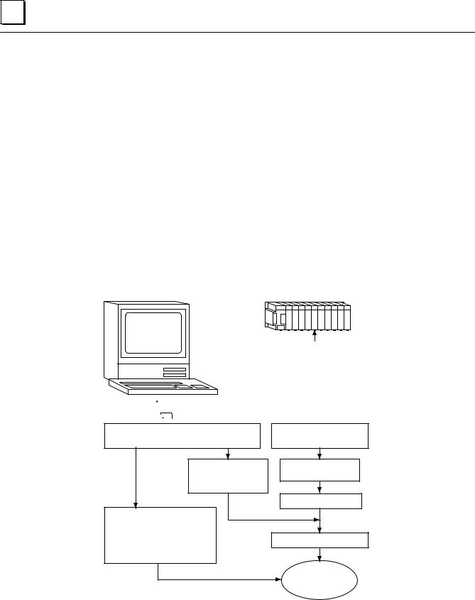
There are only a few simple tasks required to get your Ethernet Communications System working. These tasks are addressed in detail later in this manual.
1.Install the Ethernet Interface into the Series 90-30 baseplate and connect it to the network.
2.Configure the Ethernet Interface using Logicmaster 90 Configuration software or CIMPLICITY Control.
3.Power up the Series 90-30 PLC, store the configuration, and power-up the PLC again.
4.Add COMMREQ functions in your ladder program if you need client capability.
The figure below illustrates these tasks:
a45695
Series 90±30
PLC
User supplied |
Ethernet Interface |
IBM PC compatible
 Programming/Configuration software
Install |
Install |
Programming/Configuration software |
Interface in PLC |
Use Configuration |
Connect Interface |
package to create |
to Network |
interface |
|
|
Power±up PLC |
Use programmer package to program
COMMREQs to initiate
communications from Power±up PLC again your Series 90±70 PLC*
Fully Operational
Interface
*Optional if client capability is needed
Figure 1-2. The Main Tasks for Installing the Ethernet Interface
1-4 |
TCP/IPEthernetCommunicationsUser's Manual ± August1997 |
GFK-1084B |

1 |
Quick Guide to the Manual
The table below breaks down the tasks shown in Figure 1-2 and identifies where in the manual they are described.
Tasks |
|
Where to go in the Manual |
Installing the Interface |
|
Chapter 2. Installing the Ethernet Interface |
|
|
Procedure1. Installing the Interface |
Configuring the Interface |
|
Procedure2. Configuring the Interface |
|
||
Powering-up the PLC |
|
Procedure3. VerifyingProper Power-Up |
|
|
Operation of the Configured |
|
|
Interface |
PINGApplicationConnectionTests |
|
Procedure4. PingingtheTCP/IPInterfaces |
|
|
on the Network |
PLC Ladder Programming(COMMREQ) |
|
Chapter 3 ProgrammingCommunicationsRequests |
Troubleshooting the Interface on |
|
Chapter 4. Troubleshooting |
the Network |
|
|
|
|
|
GFK-1084B |
Chapter 1 Introduction |
1-5 |

Chapter Installing the Ethernet Interface
2
This chapter describes the basic features of the Ethernet Interface, its installation, configuration, and a procedure for its initial checkout on your Ethernet cable. The chapter first provides a hardware overview of the Ethernet Interface. It is then divided into four Installation Procedures, each providing an overview of the procedure and then explaining the detailed steps to be performed.
As you work through a procedure you may encounter references to the appendices and other chapters in this manual. These references provide more detailed information about the subject under discussion.
The installation procedures described in this chapter are listed below:
HProcedure 1: Mounting the Ethernet Interface on the PLC Baseplate - Required
HProcedure 2: Configuring the Ethernet Interface - Required
HProcedure 3: Verifying Proper Power-Up of the Ethernet Interface - Required
HProcedure 4: ªPingingº the Ethernet Interfaces on the Network - Optional
Some of the procedures require prior Ethernet cable plant design and installation.
By completing the Installation Procedures you will gain an understanding of the parts of the network and how they fit together. You will also have confidence that your equipment is working properly.
Ethernet Interface Hardware Overview
The Ethernet Interface is mounted on the Series 90-30 PLC baseplate. It is connected to an Ethernet network via a user-provided transceiver cable and transceiver. The following figure shows the layout of the Ethernet Interface.
GFK-1084B |
2-1 |
2 |
a45481c
CMM 321 |
OK |
OK |
|
ETHERNET |
LAN |
LAN |
|
INTERFACE |
|||
SER |
SER |
||
|
|||
|
STAT |
STAT |
|
|
|
RESTART |
|
|
|
STATION |
|
|
|
MANAGER |
|
|
|
PORT |
|
|
|
(PORT 1) |
|
|
|
STATION |
|
|
|
ADDRESS |
|
|
|
LABEL |
|
|
|
SOFTWARE |
|
|
|
LOADER |
|
|
|
PORT |
|
|
|
(PORT 2) |
|
|
|
SERIAL |
|
|
|
NUMBER |
|
|
|
LABEL |
|
|
|
AAUI |
|
|
|
TRANSCEIVER |
|
|
|
PORT |
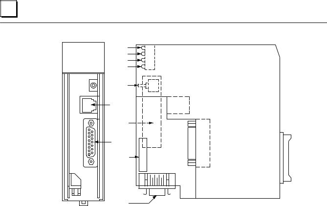
Figure 2-1. Ethernet Interface
The Ethernet Interface has several user-accessible elements.
Four LEDs are located at the top of the board. The Restart button is located immediately below the LEDs. The RS-232 serial port with the RJ-11 connector (similar to a modular telephone connector) is the Station Manager port. The RS-485 serial port with the 15-pin ªDº connector located below the Station Manager port is the module's Software Loader port. The 14-pin AAUI connector, facing downward, is the Transceiver port.
The Restart button, Station Manager port, Software Loader port, MAC address label, and serial number label are normally concealed by the front cover. Remove the front cover to access them.
2-2 |
TCP/IPEthernetCommunicationsUser's Manual - August1997 |
GFK-1084B |

2 |
Board Indicators
There are four LEDs on the Ethernet Interface: OK, LAN, SER, and STAT. Each of these LEDs can be ON, OFF, BLINKING slow, or BLINKING fast. They indicate the state of the Interface, traffic on the network port (LAN ONLINE LED), and that an exception event has occurred.
All LEDs are briefly turned ON whenever the Restart button (described below) is released. This permits the operator to verify that all LEDs are operational.
See ªProcedure 3. Verifying Proper Power-Up of the Ethernet Interfaceº for more LED information.
Restart Button
The Restart button serves four functions: LED test, Restart, Restart and enter Software Load state, and Restart and enter Maintenance state. These four functions behave similarly in all states except for the Software Load state. While in this state, pressing the button will cause an immediate restart into the Operational state if the software in the Ethernet Interface has not been corrupted or erased. If the software has been corrupted or erased, pressing the button will cause an immediate restart back into the Software Load state. The following text describes Restart button behavior while not in the Software Load state.
Pressing the Restart button will disrupt communications.
LED Test: Any time the Restart button is released all the LEDs flash ON. The operator should visually verify that all the LEDs go OFF and then ON at this time. Then the Interface performs either a restart, a restart and enter Software Load state, or a restart and enter Maintenance state, depending on the duration that the operator depresses Restart.
Restart: Pressing the Restart button momentarily (less than 5 seconds) requests a restart of the Ethernet Interface. When the Restart button is pressed, all LEDs go out. When it is released, all LEDs flash ON, then power-up diagnostics run, and the software on the Interface is restarted into the Operational state.
Restart and Enter Software Load State: Pressing and holding the Restart button for between 5 and 10 seconds forces a restart and requests entrance to the Software Load state. A reload is used to install a software update into the module and is not part of normal operation. When the Restart button is pressed, all LEDs go out. After 5 seconds have elapsed, the STAT LED (bottom LED) comes ON, to indicate that the Ethernet Interface will request a reload. After the Restart button is released, all LEDs flash ON, then pow- er-up diagnostics run, and the Ethernet Interface waits to be loaded with all LEDs blinking in unison.
GFK-1084B |
Chapter 2 Installing the EthernetInterface |
2-3 |

2 |
Notes
Reloading the Ethernet Interface requires the attachment of the PC Software Loader to the Software Loader port and initiating a load with the PC Software Loader. The PC Software Loader is a separate software utility which updates the communications software in the Ethernet Interface. This utility is supplied with any updates to the Ethernet Interface software. See Appendix E for more information.
At any time before you initiate a load with the PC Software Loader, you can restart the Ethernet Interface by pressing the Restart button. Pressing this button will immediately cause the board to restart. If the reload has been initiated, see Appendix E for more information.
Restart and Enter Maintenance State: Pressing and holding the Restart button for more than 10 seconds forces a restart and requests entrance to the Maintenance state. Maintenance state must be invoked to change Advanced Parameters. While in Maintenance state, all Advanced Parameters revert to their default value. When the Restart button is pressed, all LEDs go out. After 5 seconds, the STAT LED comes ON, then after 10 seconds have elapsed, the STAT and SER LEDs both come ON, to indicate that the Ethernet Interface will request entry to the Maintenance state. After the Restart button is released, all LEDs flash ON then power-up diagnostics run and the Ethernet Interface enters the Maintenance state.
Notes
In any case, any data being transferred by the Ethernet Interface at the time of the Restart will be lost.
The Restart button is not operable during the diagnostic phase of power-up. The Ethernet Interface is in diagnostic phase when the OK LED is BLINKING fast and other LEDs are OFF.
Serial Ports
There are two serial ports on the Ethernet Interface: the Station Manager port (port 1) and the Software Loader port (port 2).
The Station Manager Port
The 6-pin, RJ-11 ªphone jackº, RS-232 port is used to connect a terminal or terminal emulator to access the Station Manager software on the Ethernet Interface. A cable is needed to connect the terminal or emulator to the Ethernet Interface (see Appendix B, Communications Ports Characteristics).
The Software Loader Port
The 15-pin, D-type, RS-485 port is used to connect to the PC Software Loader in case the communications software in the Ethernet Interface needs to be updated. The characteristics of this port are given in Appendix B, Communications Ports Characteristics.
2-4 |
TCP/IPEthernetCommunicationsUser's Manual - August1997 |
GFK-1084B |

2 |
AAUI (Transceiver) Port
The 14-pin AAUI port provides the electrical and mechanical interface to the user-pro- vided IEEE 802.3 transceiver cable, which connects the AAUI Port to an external Ether- net-compatible transceiver (see Appendix B for the characteristics of the AAUI Port). The external transceiver is directly connected to the Ethernet cable.
Default Station Address Label
The Default Station Address label lists the MAC address to be used by this Interface.
Serial Number Label
The Serial Number Label indicates the serial number of this Interface.
GFK-1084B |
Chapter 2 Installing the EthernetInterface |
2-5 |

2 |
Procedure 1: Installing the Ethernet Interface in the PLC
This section describes the physical mounting of the Ethernet Interface onto the Series 90-30 PLC baseplate. For information on the installation procedures for the baseplate, Series 90-30 CPU, Power Supply, and other Series 90-30 modules, refer to GFK-0356,
Series 90-30 Programmable Controller Installation Manual.
Equipment Required to Perform the Installation Procedures
In addition to the Ethernet Interface, make sure you have the items listed below before you begin.
HA Series 90-30 PLC CPU baseplate, or any Series 90-30 baseplate and a Series 90-30 CPU (version 5.03 or higher) with power supply.
HAn operating Logicmastert 90-30 system release 6.0 or higher, or CIMPLICITY Control (runs on a personal computer).
HAn Ethernet-compatible AAUI transceiver and Ethernet cables. (See Appendix B for more information.)
HA serial cable for the Station Manager port on the Ethernet Interface (see Appendix B). Optional
HA terminal or IBM-compatible personal computer equipped with terminal emulation software. Optional
Note
If your installation requires CE Mark compliance, please refer to GFK-1179, Installation Requirements for Conformance to Standards, shipped with the PLC programming software, for additional guidelines.
Ethernet Interface Installation
Use the following instructions as a guide when inserting a module into a slot in a baseplate. These instructions assume that the power suppy on the baseplate is to your left.
Warning
Do not insert or remove modules with power applied. This could cause the PLC to Stop, damage the module, or result in personal injury.
1.Be sure the Series 90-30 PLC baseplate power is OFF.
2.Align the module with the desired base slot and connector. Tilt the module upwards so that the top rear hook of the module engages the slot on baseplate.
3.Swing the module downward until the connectors mate and the lock-lever on the bottom of the module snaps into place engaging the baseplate notch.
2-6 |
TCP/IPEthernetCommunicationsUser's Manual - August1997 |
GFK-1084B |

2 |
4.Visually inspect the module to be sure that it is properly seated.
5.Remove the front cover of the Interface.
6.Connect the transceiver cable into the 14-pin AAUI Port of the Ethernet Interface. Secure the cable. The other end of the transceiver cable should be connected to an external IEEE 802.3 compatible transceiver which is attached to the Ethernet network. If the transceiver has a switch or jumper for SQE, it must be enabled. (Note: The transceiver cable may be built-in to the transceiver or removable.)
7.Replace the front cover and restore power to the baseplate.
8.Use Logicmaster software, CIMPLICITY Control, or a Hand Held Programmer to stop the CPU.
9.Continue with Procedure 2: Configuring the Ethernet Interface.
Note
An Ethernet Interface can be mounted on a CPU baseplate, an expansion baseplate, or a remote baseplate. However, due to power requirements, only two Ethernet Interfaces are permitted per baseplate.
GFK-1084B |
Chapter 2 Installing the EthernetInterface |
2-7 |
2 |
Procedure 2a: Configuring the Ethernet Interface with Logicmaster 90-30 Configuration Software
Before you can use the Ethernet Interface with the Series 90-30 PLC, you must configure the Interface using Logicmastert 90-30 configuration software or CIMPLICITYR Control (see Procedure 2b for configuring using CIMPLICITY Control). The Logicmaster 90-30 configuration software allows you to specify the modules and I/O that will reside in your Series 90-30 PLC rack(s). The Hand Held Programmer may not be used to configure the Interface.
For the Ethernet Interface specifically, the configuration software allows you to:
HDefine the status address of the Ethernet Interface
HAssign the IP Address for the Ethernet Interface, and optionally the Subnet Mask and the Gateway Address.
HConfigure the serial ports (optional).
To configure the Ethernet Interface, access the I/O Configuration rack screen in the
Logicmaster 90-30 Configuration Package, and do the following:
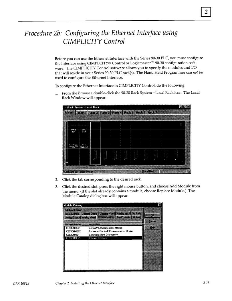
1.Move the cursor to the desired rack and slot location. The slot may be either unconfigured or previously configured.
2.Press the Communications softkey, i.e., Comm (F6). Your screen display will change to the one shown on the following page.
2-8 |
TCP/IPEthernetCommunicationsUser's Manual - August1997 |
GFK-1084B |
2 |
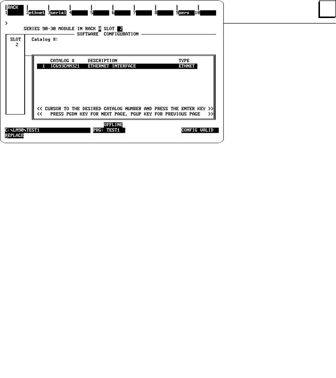
3.Press ethnet (F2). Your screen display will change to the one shown below.
4.Press Enter to select the Ethernet Interface. You will then see the screen shown on the following page.
GFK-1084B |
Chapter 2 Installing the EthernetInterface |
2-9 |
2 |
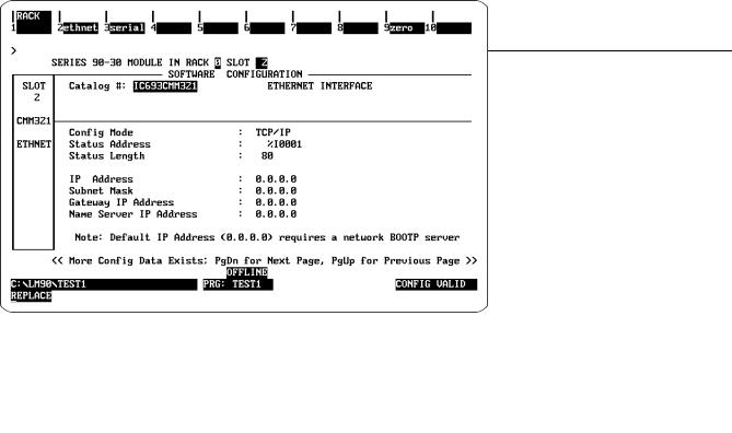
Configuration Mode: This is currently fixedasTCP/IP.
Status Address: The Status Address is the location of the LAN Interface Status (LIS) bits (16 bits) and the Channel Status bits (64 bits). The Channel Status bits are always located immediately following the LAN Interface Status bits.
Note
Do not use the 80-bits assigned to the LIS bits and Channel Status bits for other purposes or your data will be overwritten.
Status Length: This is fixed at 80 bits (the sum of the LIS bits and the Channel Status bits).
IP Address, Subnet Mask, Gateway Address, and Name Server IP Address: The values for the IP Address, Subnet Mask, and Gateway Address should be assigned by the person in charge of your network (the network administrator). TCP/IP network administrators are familiar with these parameters. It is important that these parameters are correct, otherwise the Ethernet Interface may be unable to communicate on the network and/or network operation may be corrupted. It is especially important that each node on the network is assigned a unique IP address.
2-10 |
TCP/IPEthernetCommunicationsUser's Manual - August1997 |
GFK-1084B |
2 |
However, if you have no network administrator and a simple isolated network with no gateways, you can use the following range of values for the assignment of local IP addresses:
3.0.0.1First PLC
3.0.0.2Second PLC
3.0.0.3Third PLC
. |
. |
. |
. |
. |
. |
3.0.0.255 |
Logicmaster TCP or host |
Also, on an isolated network, the Subnet Mask, Gateway IP address, and Name Server IP address can all be 0.0.0.0. (The Name Server IP address is not currently used and is reserved for future use.)
Note
If the isolated network is ever connected to another network, the IP addresses3.0.0.1through 3.0.0.255 must not be used and the Subnet Mask and Gateway IP address must be assigned by the Network Administrator.
The IP addresses must be assigned so that they are compatible with the connected network. Refer to Appendix C for more information on addressing.
See also the section ªDetermining If an IP Address Has Already Been
Usedº in Procedure 4.
5.Optionally, after you have assigned the IP address, etc., press Page Down to display the following screen.
GFK-1084B |
Chapter 2 Installing the EthernetInterface |
2-11 |

2 |
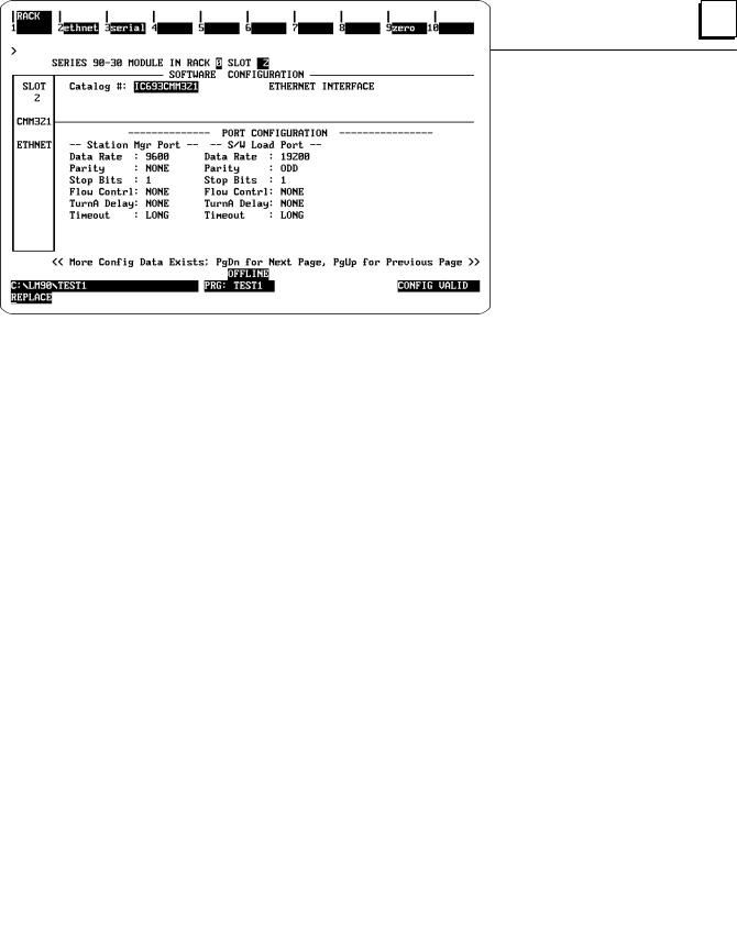
The Logicmaster 90-30 Configurator also allows you to optionally configure the Data Rate, Parity, Stop Bits, Flow Control, Turn-around Delay, and Timeout for each of the two serial ports (Station Manager Port and Software Loader Port. The defaults for both ports are shown on the previous screen.
Data Rate: Data rate (bits per second or bps) for the port. Choices are 300, 600, 1200,
2400, 4800, 9600[, or 19200*.
Parity: Type of parity to be used for the port. Choices are NONE[, EVEN, or ODD*.
Stop Bits: Enter the number of stop bits. Choices are 1*[ or 2.
Flow Control: Type of flow control to be used for the port. Choices are HARDWARE or
NONE*[.
Turnaround Delay: Turnaround delay time to be used for the port. Choices are NONE*[,
10 ms, 100 ms, or 500 ms.
Timeout: Length of timeouts used for the port. Choices are LONG*[,
MEDIUM, SHORT, or NONE.
* Default selection for the Software Loader Port. [ Default selection for the Station Manager Port
6.Press the Escape key to return to the rack display. Press Escape again to save the configuration to disk.
7.Power up the PLC. (See Procedure 3 to verify proper power-up of the Ethernet Interface.)
8.Store the configuration to the PLC via the built-in serial port on the power supply.
Refer to GFK-0466, Logicmaster 90 Series 90-30/20/Micro Programming Software User's Manual for more information on configuring the Ethernet Interface using Logicmaster 90-30 software.
2-12 |
TCP/IPEthernetCommunicationsUser's Manual - August1997 |
GFK-1084B |


2 |
3.0.0.1First PLC
3.0.0.2Second PLC
3.0.0.3Third PLC
. |
. |
. |
. |
. |
. |
3.0.0.255 |
Logicmaster TCP or host |
On an isolated network, the Subnet Mask, Gateway IP address, and Name Server
IP address can all be 0.0.0.0.
Note
If the isolated network is ever connected to another network, the IP addresses3.0.0.1through 3.0.0.255 must not be used and the Subnet Mask and Gateway IP address must be assigned by the Network Administrator.
The IP addresses must be assigned so that they are compatible with the connected network. Refer to Appendix C for more information on addressing.
See also the section ªDetermining If an IP Address Has Already Been
Usedº in Procedure 4.
DConverter: Allows you to account for the power consumption added by a serial port converter (measured in watts). Choices are 0, 0.500, and 0.600.
DAAUI Transceiver: Allows you to account for the power consumption added by the AAUI Transceiver attached to the Ethernet module (measured in watts). The valid range is 0.250 to 1.75.
6.Optionally, after you have completed the Settings tab, you can configure parameters for the Station Manager and Software Load ports by clicking the appropriate tab. The details of the parameter settings for these ports are as follows:
DData Rate: Data rate (bits per second or bps) for the port. Choices are 1200, 2400, 4800, 9600[, or 19200* .
DParity: Type of parity to be used for the port. Choices are None[, Even, or Odd*.
D Stop Bits: Enter the number of stop bits. Choices are 1*[ or 2.
DFlow Control: Type of flow control to be used for the port. Choices are Hardware or None*[.
DTurnaround Delay: Turnaround delay time to be used for the port. Choices are
None* [, 10 ms, 100 ms, or 500 ms.
DTimeout: Length of timeouts used for the port. Choices are Long*[, Medium, Short, or None.
*Default selection for the Software Loader Port.
[Default selection for the Station Manager Port
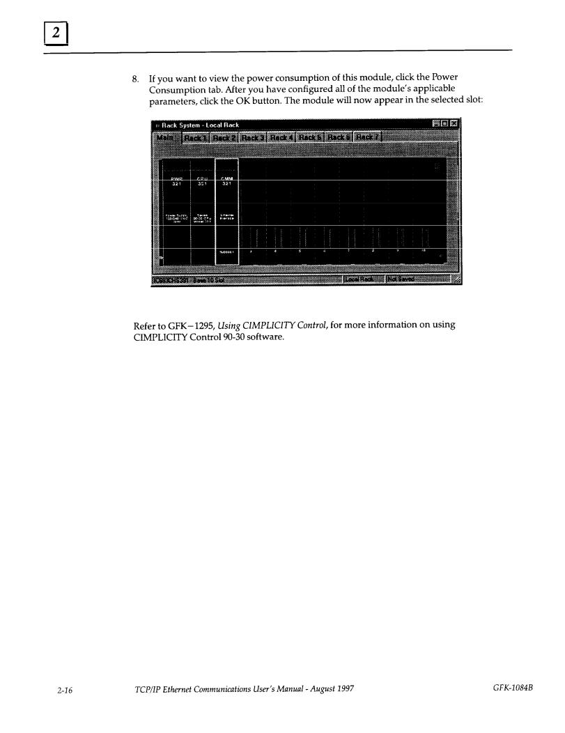
7.If you want to assign variable names to specific points on the Ethernet card, click the Point Reference tab. To assign a variable to a point, double-click the reference address you want. The Insert Variable dialog box will appear, which will allow you to fill in a variable name and description.
GFK-1084B |
Chapter 2 Installing the EthernetInterface |
2-15 |
2 |
Procedure 3: Verifying Proper Power-Up of the Ethernet Interface
Powering-up the Ethernet Interface
After configuring the Interface as explained in Procedure 2, follow the procedure below to verify that the Ethernet Interface is operating correctly.
1. Turn power OFF to the PLC for 3±5 seconds, then turn the power back ON. This will initiate a series of diagnostic tests.
The OK LED will blink indicating the progress of power-up.
2.The LEDs will have the following pattern upon successful power-up. At this time the Ethernet Interface is fully operational and on-line.
LED |
Ethernet Interface Online |
|
|
|
|
OK |
F |
(On) |
|
|
|
LAN |
F/: (On/Traffic) |
|
|
|
|
SER |
` (Off) |
|
|
|
|
STAT |
F |
(On) |
|
|
|
If STAT LED is OFF, check the PLC Fault Table. Alternatively, use the Station Manager LOG command as explainedin GFK-1186, TCP/IPEthernetCommunicationsStationManager Manual.
Problems During Power-up
If a problem is detected during power-up, the Ethernet Interface may not transition directly to the Operational State. If the Interface does not transistion to Operational, check the LED pattern on the Interface and refer to Figure 2-2 to find out where the Interface stopped. Refer to Table 2-1 for corrective actions.
GFK-1084B |
Chapter 2 Installing the EthernetInterface |
2-17 |
Loading...