


Operator's Manual
®
42"- 2 STAGE SNOW THROWER TRACTOR ATTACHMENT
Model No. 486.248381
CAUTION:
Before using this product, read this manual and follow all Safety Rules and Operating Instructions.
Sears, Roebuck and Co., Hoffman Estates, IL 60179 U.S.A. www.sears.com/craftsman
STOP
DO NOT RETURN TO STORE For Missing Parts or Assembly Questions Call 1-866-576-8388
•Safety
•Assembly
•Operation
•Maintenance
•Parts
PRINTED IN U.S.A. |
FORM NO. 40242 (REV. 12/13/07) |
|
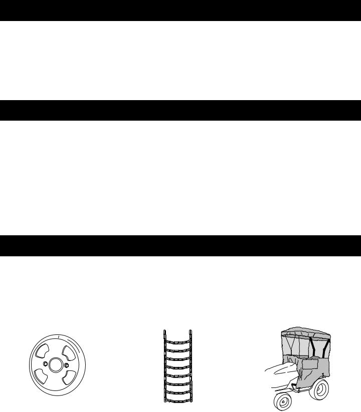
TABLE OF CONTENTS
ACCESSORIES............................................................... |
2 |
SAFETY RULES.............................................................. |
3 |
FULL SIZE HARDWARE CHART.................................... |
4 |
CARTON CONTENTS..................................................... |
6 |
ASSEMBLY...................................................................... |
7 |
OPERATION.................................................................. |
27 |
MAINTENANCE............................................................. |
28 |
SERVICE AND ADJUSTMENTS. |
..................................29 |
STORAGE...................................................................... |
30 |
TROUBLESHOOTING................................................... |
30 |
REPAIR PARTS ILLUSTRATION........................ |
34,36,38 |
REPAIR PARTS LIST........................................... |
35,37,38 |
SLOPE GUIDE............................................................... |
39 |
PARTS ORDERING/SERVICE.................... |
BACK COVER |
WARRANTY
ONE YEAR FULL WARRANTY
When operated and maintained according to the instructions supplied with it, if this Snowthrower fails due to a defect in material or workmanship within one year from the date of purchase, call 1-800-4-MY-HOME® to arrange for free repair (or replacement if repair proves impossible).
If this product is used for commercial or rental purposes, this warranty applies for only 90 days from the date of purchase.
This warranty gives you specific legal rights, and you may also have other rights which vary from state to state.
Sears, Roebuck and Co., D817WA, Hoffman Estates, IL 60179
ACCESSORIES AND ATTACHMENTS
Theseandotheraccessoriesarerecommendedforusewithyourunit.Call1-800-4-MY-HOME®tofindoutiftheyareavailable. If available, they may be purchased at most Craftsman outlets or by calling 1-800-4-MY-HOME®.
WHEEL WEIGHT |
TIRE CHAINS |
SNOW CAB |
||
|
|
|
|
71-24276 |
|
|
|
|
|
|
|
|
|
|
|
|
|
|
|
|
|
|
|
|
|
|
|
|
|
|
|
|
|
|
|
|
|
|
|
The model number and serial numbers will be found on a |
MODEL NUMBER: |
486.248381 |
|
decal attached to the snow thrower. |
SERIAL NUMBER: |
__________________ |
|
|
|||
You should record both the serial number and the date of |
DATE OF PURCHASE: |
__________________ |
|
purchase and keep in a safe place for future reference. |
|||
|
|
||
|
|
|
2

SAFETY
Any power equipment can cause injury if operated improperly or if the user does not understand how to operate the equipment. Exercise caution at all times, when using power equipment.
•Read this owner's manual carefully and know how to operate your snow thrower and how to stop the unit and disengage the controls quickly.
•Never allow children to operate the equipment.
•Never allow adults to operate the equipment without proper instruction.
•Keep the area of operation clear of all persons, especially small children, and pets.
•Thoroughly inspect the area where the equipment is to be used and remove all door mats, sleds, boards, wires and other foreign objects.
•Disengage all clutches and shift into neutral before starting engine.
•Do not operate equipment without wearing adequate winter outer garments.
•Wear substantial footwear which will protect feet and improve footing on slippery surfaces.
•Check fuel before starting the engine. Do not remove the fuel cap or fill the fuel tank while the engine
is running or hot. Do not fill the fuel tank indoors. Gasoline is an extremely flammable fuel.
•Make sure the snow thrower height is adjusted to clear the type surface it will be used on.
•Do not use the snow thrower without the rear weight attached to the tractor.
•Never make any adjustments while the engine is running.
•Always wear safety glasses or eye shield during operation or while performing adjustment or repair.
•Do not place hands or feet near rotating parts. Keep clear of the discharge opening at all times.
•Use extreme caution when operating on or crossing gravel surfaces.
•Do not carry passengers.
•After striking a foreign object, stop the engine, remove the wire from the spark plug and then thoroughly inspect the snow thrower for damage. Repair any damage before restarting and operating the snow thrower.
•If the snow thrower starts to vibrate abnormally, stop the engine immediately and check for the cause. Vibration is generally a warning of trouble.
•Stop the engine whenever you leave the operating position, before unclogging the snow thrower or making any adjustments or inspections.
•Take all possible precautions when leaving the unit unattended. Disengage the attachment clutch lever or switch, lower the snow thrower, shift into neutral, set the parking brake, stop the engine and remove the key.
•When cleaning, repairing or inspecting, make certain all moving parts have stopped. Disconnect the spark plug wire and keep it away from the plug to prevent accidental starting.
•Do not run engine indoors except when transporting the snow thrower in or out of the building. Open the outside doors. Exhaust fumes are dangerous.
•Do not clear snow across the face of slopes. Exercise extreme caution when changing direction on slopes. Do not attempt to clear steep slopes. Refer to the slope guide on page 39 of this manual.
•Never operate the snow thrower without guards, plates or other safety protection devices in place.
•Never operate the snow thrower near glass enclosures, automobiles, window wells, drop offs etc. without proper adjustment of the snow thrower discharge angle.
•Never direct discharge at bystanders or allow anyone in front of the snow thrower.
•Never run the snow thrower into material at high speeds.
•Do not overload the machine capacity by attempting to clear snow at too fast a rate.
•Never operate the machine at high transport speed on slippery surfaces. Look behind and use care when backing up.
•Watch for traffic and stay alert when crossing or operating near roadways.
•Disengage power to the snow thrower when transporting or when not in use.
•Use only attachments and accessories approved by the manufacturer of the snow thrower (such as wheel weights, counter weights, cabs etc.)
•Never operate the snow thrower without good visibility or light.
Look for this symbol to point out important safety precautions.It means — Attention!! Become alert!! Your safety is involved.
3

HARDWARE PACKAGE CONTENTS
SHOWN ACTUAL SIZE
A |
B |
C |
D |
E |
F |
G |
H |
I |
J |
K |
L |
M |
N |
O |
|
|
|
Z |
P |
|
T |
U |
|
S |
||
|
AA |
||
|
|
||
|
|
|
|
|
BB |
|
V |
|
R |
W,X |
CC |
|
|
Y |
Q |
|
DD |
|
|
|
|
|
EE |
NOT SHOWN ACTUAL SIZE
|
|
|
|
GG |
HH |
|
II |
FF |
|
|
|
|
|
||
|
|
|
|
|
|
||
|
|
|
|
|
|
|
|
JJ |
|
KK |
LL |
|
MM |
NN |
|
|
|
|
|
OO |
|||
|
|
|
|
|
|
||
|
|
|
|
|
|
|
|
|
PP |
|
RR |
SS |
|
TT |
|
|
|
|
|
|
|||
|
|
|
|
|
|
|
4
REF. |
QTY. |
DESCRIPTION |
REF. |
QTY. |
DESCRIPTION |
|
|
|
|
|
|
A |
1 |
Hex Bolt, 1/2" x 1-1/4" |
X |
3 |
Washer, 3/8" |
B |
1 |
Hex Bolt, 3/8" x 3-1/4" |
Y |
2 |
Bowed Washer |
C |
2 |
Hex Bolt, 3/8" x 1" |
Z |
6 |
Flanged Nut, 1/4" |
D |
2 |
Hex Bolt, 5/16" x 1-3/4" |
AA |
1 |
Flanged Nut, 5/16" |
E |
4 |
Hex Bolt, 5/16" x 3/4" |
BB |
12 |
Flanged Nut, 3/8" |
F |
6 |
Hex Bolt, 1/4" x 1" |
CC |
21 |
Nylock Nut, 5/16" (2 spare parts) |
G |
6 |
Hex Bolt, 3/8" x 1" (Thread Forming) |
DD |
2 |
Hex Lock Nut, 3/8" |
H |
2 |
Hex Bolt, 3/8" x 3/4" (Thread Forming) |
EE |
1 |
Nylock Nut, 1/2" |
I |
2 |
Hex Bolt, 5/16" x 3/4" (Thread Forming) |
FF |
1 |
Tarp Strap |
J |
2 |
Slotted Truss Head Bolt, 3/8" x 1" |
GG |
1 |
Spring |
K |
6 |
Carriage Bolt, 3/8" x 1" |
HH |
3 |
Chute Keeper |
L |
2 |
Carriage Bolt, 5/16" x 1-3/4" |
II |
1 |
Trunnion |
M |
2 |
Carriage Bolt , 5/16" x 1-1/4" |
JJ |
2 |
Hairpin Cotter, 5/64" |
N |
8 |
Carriage Bolt, 5/16" x 1" |
KK |
4 |
Hairpin Cotter, 1/8" |
O |
2 |
Carriage Bolt, 5/16" x 3/4" |
LL |
1 |
Hairpin Cotter, 3/32" |
P |
4 |
Shoulder Bolt |
MM |
2 |
Lock Pin |
Q |
2 |
Shoulder Bolt |
NN |
1 |
Plastic Cap |
R |
2 |
Shear Bolt (spare parts) |
OO |
2 |
Nylon Tie |
S |
7 |
Lock Washer, 3/8" |
PP |
2 |
Chain, Tensioning |
T |
7 |
Washer, 1/4" |
2 |
Tail Reflector |
|
U |
6 |
Washer, 5/16" |
RR |
1 |
Small Spacer |
V |
8 |
Washer, 1/2" |
SS |
1 |
Large Spacer |
W |
1 |
Washer, 3/8" (Thin) |
TT |
1 |
Pulley |
|
|
|
|
|
|
5

CARTON CONTENTS
1. |
Cross Brace (Weight Tray) |
13. |
Plastic Keg |
2. |
Side Braces (2) (Weight Tray) |
14. |
L.H. Hanger Bracket (Outside Mounting) |
3. |
Left Hand Side Plate |
15. |
R.H. Hanger Bracket (Outside Mounting) |
4. |
Right Hand Side Plate |
16. |
Clutch Idler Assembly |
5. |
Anti-rotation Bracket |
17. |
V-Belt, Drive (Short) #46989 |
6. |
Engagement Rod (Not used on some models) |
18 |
V-Belt, Drive (Long) #48138 |
7. |
Suspension Arms (2) |
19. |
V-Belt, Auger (Attached to Housing Assembly) |
8. |
Engine Pulley Keeper (Not used on some models) |
20. |
Chute and Control Cable Assembly |
9. |
Chute Crank Rod Assembly |
21. |
Housing Assembly |
10. |
Support Tube, Crank Rod |
22. |
Weight Tray |
11. |
Lift Handle and Cable |
23. |
L.H. Hanger Bracket (Inside Mounting) |
12. |
Cable Bracket |
24. |
R.H. Hanger Bracket (Inside Mounting) |
|
|
|
Hardware Package (Stored inside Plastic Keg) |
1 |
2 |
3 |
4 |
5 |
6 |
|
|
|
7
8
|
|
13 |
|
9 |
|
14 |
|
10 |
15 |
||
|
|||
|
|
||
11 |
|
21 |
|
|
12 |
|
16
20
22
17 18
19
23
24
6
TOOLS REQUIRED FOR ASSEMBLY
(2) 7/16" Wrenches
(2) 1/2" Wrenches
(2) 9/16" Wrenches
(2) 3/4" Wrenches
(1) Screw Driver
(1) Knife
ADDITIONAL ITEMS REQUIRED
General Purpose Grease
ASSEMBLY
IDENTIFYYOU TRACTOR
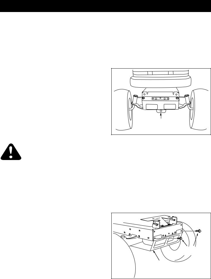
STEP 1: (SEE FIGURE 1)
•Look under the front of your tractor. If there is a single mower deck suspension bracket located underneath the middle of the front axle, continue on to step
2. If your tractor does not have a mower deck suspension bracket underneath the middle of the front axle, skip to step 21 on page 13 for tractors
with dual suspension brackets.
REMOVAL OF PARTS FROM CARTON
•Remove all parts and hardware packages from the carton. Lay out parts and hardware and identify using the illustrations on pages 4 and 6.
NOTE: Not all of the supplied parts and hardware will be needed for your particular tractor. Unneeded items may be discarded after you have completed assembly and checked operation of unit. DO NOT DISCARD the two spare shear bolts (R) and 5/16" nylock nuts (CC). Refer to the Service and Adjustments section on page 29.
CAUTION: Before starting to assemble the snowthrower,removethesparkplugwire(s), set the parking brake and remove the key from the tractor ignition.
TRACTOR PREPARATION
Before performing these instructions, refer to the Service and Adjustments section of your tractor owner's manual for specific safety instructions.
•Allow engine, muffler and exhaust deflector to cool before beginning.
•Remove any front or rear attachment which is mounted to your tractor.
•Remove the mower deck. Refer to your tractor owner's manual for removal instructions. Mark all loose parts and save for reassembly.
•Remove the tractor hood. Refer to your tractor owner's manual for removal instructions.
IMPORTANT: Right hand (R.H.) and left hand (L.H.) side of the tractor are determined from the operators position while seated on the tractor.
MOWER DECK
SUSPENSION
BRACKET
FIGURE 1
INSTRUCTIONS FOR TRACTORS WITH SINGLE FRONT DECK SUSPENSION BRACKET
STEP 2: (SEE FIGURE 2)
•Remove the browning shield from the front of the tractor as shown. Hold onto the shield as you remove the second screw to prevent it from falling.
•Be sure to reinstall the browning shield when so instructed in step 3.
|
REMOVE |
|
FRONT SCREWS |
|
REMOVE |
|
BROWNING SHIELD |
FIGURE 2 |
RIGHT SIDE VIEW |
7
INSTALL SIDE PLATES
STEP 3: (SEE FIGURE 3)
•Fasten the R.H. Side Plate (bend facing out) to the front three holes in the tractor frame using three 3/8" x 1" carriage bolts (K), three 1/2" washers (V)
(see note) and three 3/8" flange nuts (BB). For the rear hole, use a 5/16" x 1" carriage bolt (N), a 1/2" washer (V) and a 5/16" nylock nut (CC). Place the 1/2" washers (V) between the tractor frame and the side plate. Repeat for L.H. side plate.
•Reinstall the browning shield onto the tractor frame using the original screws.
NOTE: If there is an engine mounting plate (shown with dotted lines) leave the 1/2 washer off the bolt that goes through the plate.
5/16" x 1" |
|
ENGINE MOUNTING |
|
CARRIAGE BOLT (N) |
|||
PLATE |
|||
|
|
||
|
SEE NOTE |
||
5/16" |
|
|
|
NYLOCK |
|
|
|
NUT (CC) |
|
|
|
|
|
(3) 3/8" x 1" |
|
|
|
CARRIAGE |
|
|
|
BOLTS (K) |
|
|
|
(4) 1/2" WASHERS (V) |
|
|
(3) 3/8" FLANGE NUTS (BB) |
||
FIGURE 3 |
|
RIGHT SIDE VIEW |
|
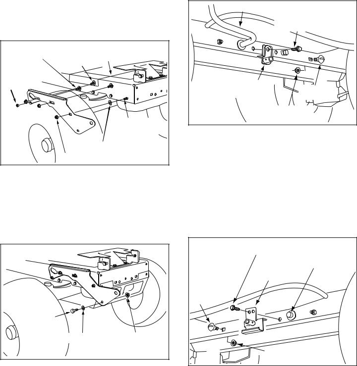
STEP 4: (SEE FIGURE 4)
•Assemble a shoulder bolt (P) and a 3/8" washer (X) to the outside of R.H. side plate, securing it with a
3/8" flanged nut (BB). Repeat for L.H. side plate.
INSTALL HANGER BRACKETS AND SHOULDER BOLTS TO OUTSIDE OF FRAME
STEP 5: (SEE FIGURE 5)
•Remove the bolt, if present, in the hole directly behind the brake rod on the left side of the tractor frame.
•Attach the L.H. Hanger Bracket (tube facing out) to the hole using a 5/16" x 3/4" self threading bolt (I).
•Install a round head shoulder bolt (Q) into the hole that is 9-1/2" to the rear of the bolt you just installed.
Secure it with a 3/8" flange nut (BB) on the inside of the frame.
|
BRAKE ROD |
|
|
|
5/16" x 3/4" SELF |
|
|
THREADING BOLT (I) |
|
L.H. HANGER |
SHOULDER |
|
BRACKET |
|
|
BOLT (Q) |
|
|
|
|
|
|
3/8" FLANGED |
|
|
NUT (BB) |
FIGURE 5 |
|
LEFT SIDE VIEW |
STEP 6: (SEE FIGURE 6)
•Remove the bracket, if present, from the hole directly behind the end of the brake rod on the right side of the tractor frame. Store the bracket and bolt.
•Attach the R.H. Hanger Bracket to the hole using a
5/16" x 3/4" self threading bolt (I).
•Install a round head shoulder bolt (Q) into the hole that is 9-1/2" to the rear of the bolt you just installed.
Secure it with a 3/8" flange nut (BB) on the inside of the frame.
|
|
5/16" x 3/4" SELF |
|
|
|
THREADING BOLT (I) |
RIGHT END OF |
|
|
|
|
|
|
R.H. HANGER |
BRAKE ROD |
|
|
|
|
|
|
BRACKET |
|
|
SHOULDER |
|
|
|
BOLT (Q) |
|
|
SHOULDER |
|
|
|
BOLT (P) |
|
|
|
3/8" WASHER (X) |
3/8" FLANGED |
|
|
|
NUT (BB) |
|
|
|
|
3/8" FLANGED |
|
FIGURE 4 |
RIGHT SIDE VIEW |
NUT (BB) |
|
|
|
||
|
FIGURE 6 |
|
RIGHT SIDE VIEW |
|
8 |
|
|
THIS SECTION IS FOR TRACTORS WITH A MANUAL ATTACHMENT CLUTCH
If your tractor has an electric attachment clutch go to step 14 on page 11.
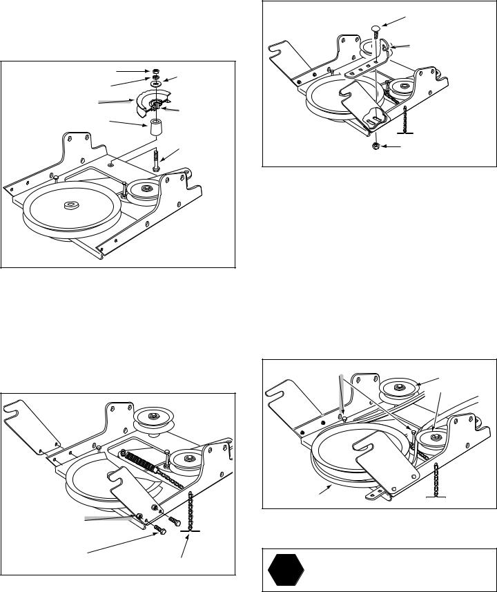
STEP 7: (SEE FIGURE 7)
•Attach the pulley (long end of hub facing down) and the large spacer (SS) to the hole shown in the clutch/ idler assembly. Use a 3/8" x 3-1/4" hex bolt (B), a 3/8" washer (X), a 3/8" lock washer (S) and a 3/8" hex lock nut (DD).
3/8" HEX LOCK NUT (DD) |
3/8" |
3/8" LOCKWASHER (S) |
WASHER (X) |
|
|
PULLEY (TT) |
LONG END |
|
|
LARGE SPACER (SS) |
OF HUB |
|
3/8" X 3-1/4" |
|
HEX BOLT |
|
(B) |
FIGURE 7
STEP 8: (SEE FIGURE 8)
•Attach the two suspension arms to the rear of the clutch/idler assembly using two 5/16" x 3/4" hex bolts
(E) and 5/16" nylock nuts (CC) for each arm. Place the arms on the outside of the frame with the notches to the rear.
•Insert a tensioning chain through the hole shown and attach the end link to the spring on the lower idler arm.
5/16" NYLOCK |
|
NUT (CC) |
|
5/16" x 3/4" |
|
HEX BOLT (E) |
TENSIONING CHAIN (PP) |
FIGURE 8
STEP 9: (SEE FIGURE 9)
•Attach the cable bracket to the slot shown in the clutch/idler assembly using a 5/16" x 3/4" carriage bolt (O) and a 5/16" nylock nut (CC). Place the bolt in the front hole of the bracket and in the end of the slot closest to the pulley. Do not tighten yet.
5/16" x 3/4" |
CARRIAGE BOLT (O) |
CABLE |
BRACKET |
5/16" NYLOCK |
NUT (CC) |
FIGURE 9
STEP 10: (SEE FIGURE 10)
•Two different length drive belts are included with your snow thrower. Tractors with manual attachment
clutches and single front deck suspension brackets use the 56" drive belt with #48138 printed on the outside of the belt. DO NOT USE the other belt.
•Slightly loosen the hex bolt next to the flat idler pulley. Install the drive belt down between the hex bolt and the flat idler pulley with the flat side of the belt against the pulley. Retighten the hex bolt.
•Loop the belt around the large v-pulley, placing it between the v-pulley and the hex bolt next to the pulley. Place the belt to the inside of the other flat idler pulley.
HEX BOLTS |
FLAT IDLER |
|
|
|
PULLEYS |
(#48138) |
|
DRIVE BELT |
|
FIGURE 10
Did you select the correct drive belt for your
STOP tractor? Using the wrong length belt may cause premature bearing or belt failure.
9
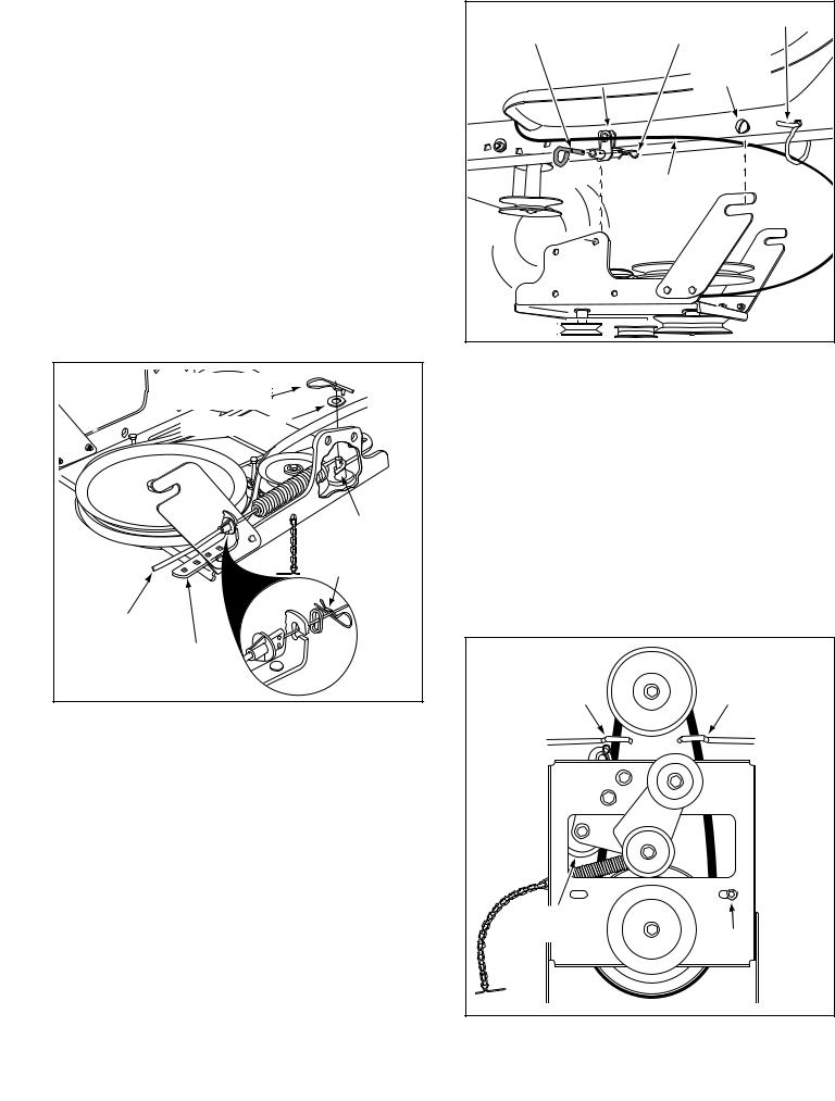
STEP 11: (SEE FIGURE 11)
•Find the cable clip that is attached to the left side of the tractor frame underneath the footrest. Open the clip and remove the mower clutch cable. Do not remove the clip from the tractor frame. The cable reattaches to the clip when using the mower deck.
•Move the attachment clutch lever on the dash panel to the disengaged position.
•Place the clutch/idler assembly on the floor on the left side of the tractor.
•Attach the tractor's mower clutch cable to the cable bracket on the clutch/idler assembly. Secure the cable housing guide (groove down) to the cable bracket using the original collar and a 5/64" hair cotter pin ( JJ).
•Place a spacer (RR) on the welded pin on the idler arm. Hook the end of the clutch cable spring over the pin and secure it with a 1/4" washer (T) and a 5/64" hair cotter pin (JJ).
•Align cable bracket with welded pin and tighten the nut assembled in step 9.
5/64" HAIR |
COTTER PIN (JJ) |
1/4" WASHER (T) |
SPACER (RR) |
5/64" HAIR |
COTTER PIN (JJ) |
TRACTOR'S |
CLUTCH CABLE |
CABLE |
BRACKET |
FIGURE 11
ATTACH CLUTCH IDLER ASSEMBLY TO TRACTOR
STEP 12: (SEE FIGURE 12)
•Attach the clutch/idler assembly to the tractor frame.
Hook the notched suspension arms onto the two shoulder bolts (Q) assembled to the outside of the tractor frame. Lift the front of the assembly and attach it to the R.H. and L.H. hanger brackets using two pivot lock pins (MM) and 1/8" hairpin cotters (KK).
•Loosely attach the mower clutch cable to the left side of the tractor frame with a nylon tie (OO). Do not pull the nylon tie completely tight. The cable may need to be removed from the nylon tie when using the mower deck.
PIVOT LOCK PIN (MM) |
1/8" HAIRPIN NYLON TIE (OO) |
|||
(use this hole) |
COTTER (KK) |
|
||
L.H. HANGER |
SHOULDER |
|
||
BRACKET |
BOLT (Q) |
|
||
|
|
|
|
|
|
|
|
|
|
|
|
|
|
|
MOWER
CLUTCH
CABLE
|
|
|
|
|
|
|
FIGURE 12 |
|
|
|
|
VIEWED FROM LEFT SIDE |
|
STEP 13: (SEE FIGURE 13)
•Assemble the drive belt onto the engine pulley first and then onto the large pulley on top of the clutch/ idler assembly. The belt must be placed inside the engine pulley belt keeper(s) and between the large pulley and the keeper bolt next to it.
IMPORTANT: Do Not assemble the "V" belt outside of the engine pulley keepers or outside of the keeper bolt next to the large pulley.
•Go to step 48 on page 21.
ENGINE |
ENGINE |
PULLEY |
PULLEY |
KEEPER |
KEEPER |
|
Left Side |
|
of Tractor |
IDLER |
|
PULLEY |
KEEPER BOLT |
|
|
FIGURE 13 |
VIEWED FROM UNDERNEATH |
10
THIS SECTION IS FOR TRACTORS WITH AN |
STEP 16: (SEE FIGURE 16) |
ELECTRIC ATTACHMENT CLUTCH |
• Hook one end of the spring supplied in the parts bag |
|
through the end link of the tensioning chain. |
|
• With the clutch/idler assembly turned upside down, |
STEP 14: (SEE FIGURE 14) |
hook the other end of the spring onto the end of the |
• Attach the two suspension arms to the rear of the |
bolt and nut which secure the idler pulley to the upper |
clutch/idler assembly using two 5/16" x 3/4" hex bolts |
idler arm. Assemble a 3/8" hex lock nut (DD) onto the |
(E) and 5/16" nylock nuts (CC) for each arm. Place the |
bolt and nut, leaving enough gap between the nuts for |
arms on the outside of the frame with the notches to |
the spring to pivot freely. |
the rear. |
• Attach a 3/32" hairpin cotter (LL) to the chain, placing |
• Insert a tensioning chain through the hole shown and |
it in the fifth link from the spring. |
attach the end link to the spring on the lower idler arm. |
|
|
|
|
SPRING |
5TH LINK |
|
|
|
ATTACH |
CHAIN |
|
|
|
(L.H. SIDE) |
||
|
|
SPRING |
|
|
|
|
HERE |
|
|
|
|
3/8" HEX |
|
|
|
|
LOCK NUT (DD) |
|
|
5/16" NYLOCK |
|
|
3/32" HAIR |
|
|
|
COTTER PIN (LL) |
||
NUT (CC) |
|
|
|
|
5/16" x 3/4" |
|
RIGHT |
LEFT |
|
|
SIDE |
SIDE |
||
HEX BOLT (E) |
TENSIONING CHAIN (PP) |
|||
|
|
|||
FIGURE 14 |
|
FIGURE 16 |
VIEW OF BOTTOM |
|
|
|
STEP 15: (SEE FIGURE 15)
•Turn the clutch/idler assembly upside down and place the extra tensioning chain (PP) through the left front hole.
LEFT FRONT HOLE
TENSIONING CHAIN (PP)
FIGURE 15
SELECT THE CORRECT DRIVE BELT
(Electric clutch tractors with a single front deck suspension bracket)
STEP 17: (SEE TABLE 1)
•Two different length drive belts are included with your snow thrower. Use the table below to select the correct drive belt for your type tractor.The part number is printed on the outside of the belt .
•Set aside the belt that is not for your tractor to avoid accidentally using it.
55" BELT (PART #46989) |
||
TRACTOR TYPE |
DECK SIZE |
CLUTCH TYPE |
|
|
|
(LT) Lawn Tractor |
38", 42" |
Electric |
|
||
56" BELT (PART #48138) |
||
TRACTOR TYPE |
DECK SIZE |
CLUTCH TYPE |
|
|
|
(LT) Lawn Tractor |
48" |
Electric |
(GT) Garden Tractor |
48", 54" |
Electric |
TABLE 1
11
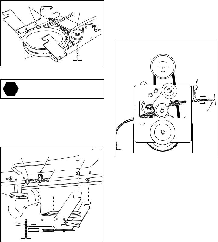
STEP 18: (SEE FIGURE 17)
•Turn the clutch/idler assembly right side up.
•Slightly loosen the hex bolt next to the flat idler pulley. Install the drive belt down between the hex bolt and the flat idler pulley with the flat side of the belt against the pulley. Retighten the hex bolt.
•Loop the belt around the large v-pulley, placing it between the v-pulley and the hex bolt next to the pulley.
HEX BOLTS |
FLAT IDLER |
|
PULLEY |
DRIVE BELT |
|
FIGURE 17
Did you choose the correct drive belt for
STOP your tractor? Using the wrong length belt may cause premature bearing or belt failure.
STEP 19: (SEE FIGURE 18)
•Attach the clutch/idler assembly to the tractor frame.
Hook the notched suspension arms onto the two shoulder bolts (Q) assembled to the outside of the tractor frame. Lift the front of the assembly and attach it to the R.H. and L.H. hanger brackets using two pivot lock pins (MM) and 1/8" hairpin cotters (KK).
PIVOT LOCK PIN (MM) |
L.H. HANGER |
SHOULDER |
|
(use second hole) |
BRACKET |
||
BOLT (Q) |
|||
|
|
1/8" HAIRPIN COTTER (KK)
STEP 20: (SEE FIGURE 19)
•Assemble the drive belt onto the engine pulley first and then onto the large pulley on top of the clutch/ idler assembly. Place the belt to the inside of the idler pulley and the belt keeper bolt located beside the large pulley.
•Place tension on the belt by pulling the left side tensioning chain (PP) out as far as the 3/32" hairpin cotter in the chain will allow. Secure the chain in this position by inserting a 1/8" hairpin cotter (KK) through the chain.
IMPORTANT: Do Not assemble the drive belt around the outside of the keeper bolt beside the large pulley.
•Go to step 48 on page 21.
CLUTCH/IDLER ASSEMBLY
ENGINE |
|
PULLEY |
1/8" HAIRPIN |
|
|
|
COTTER (KK) |
IDLER PULLEY 
CHAIN (PP)
(L.H. SIDE)

 KEEPER BOLT
FIGURE 19 |
VIEWED FROM UNDERNEATH |
|
|
|
|
|
|
|
FIGURE 18 |
|
|
|
|
VIEWED FROM LEFT SIDE |
|
12
 Loading...