


38GS
Table of contents
 Loading...
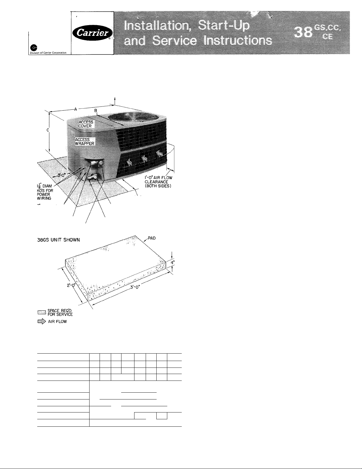
Number One
Airconditioning
Mater
Syracuse New York
Air-Cooled Condensing Units
g DIAM KOS FOR
CONTROL WIRING
SUCTION LINE CONN
SUCTION LINE
VALVE
4'-0" OVERHEAD SPACE REQ'D
FOR SERVICE AND AIR FLOW
3 -0 (BOTH SIDES)
LIQUID LINE VALVE
LIQUID LINE CONN
CONCRETE
MOUNTING
TRANSPORTATION DAMAGE
File claim with shipping company if shipment is
damaged or incomplete.
Unpackaging Unit — Move condensing unit to final
location. Open carton at end marked “compressor
end.” Slide unit from carton taking special care to
not damage service valves or grilles.
PRELIMINARY SURVEY
Consult local building codes and National
Electrical Code (NEC) for special installation
requirements.
When installing unit, allow sufficient space for
air flow clearance, wiring, refrigerant piping and
servicing unit. Position unit so water from roof or
eaves does not flow directly on top of unit.
Install unit on a solid, level mounting pad. Unit
can be attached to pad with a mastic adhesive or
by drilling holes in base pan for 1/4-in. mounting
bolts. Do not block base pan water drainage holes.
38GS,CC,CE Condensing Units Connected to
Carrier Matched Evaporators with Carrier Acces
sory Tubing — Check system refrigerant charge
when tubing lengths are above or below 25 feet.
See Refrigerant Charging (page 10) for details.
Fig. 1 — Dimensions, Connections and Mounting Pad
38GS,CC,CE Unit
Table 1 — Installation Data
38GS
014
COND UNIT 38CC
OPER WT (lb) 130 135
UNIT DIM. (ft-in.)
Length A
Width B
Height G
REFRIG CONN.(in.)
Suction (ODF)
Liquid (ODF)
*5/8-in suction connection on 38CE002
t38CE045,005 and 38GS.CC060 are factory supplied with 3/4- to
1 1/8-in suction valve adapter (field installed) for 1 1/8-in
suction line
© Carrier Corporation 1975
38CB
- - -
- - -
'l-4
% lYsT '/b I
018
1-4
024
142|149
N4
Com
036 042
030
030 036
002* 003 004 045 005
158 191
2-10V4
1-10
1-4 1 1-4 (2-0
DOtible Fittings
%
'8
048 060t
042 048 060t
193 200
----
2-0 2-0
-----
'/4t
38GS,CC,CE Condensing Units Connected to NonCarrier Evaporators — Check refrigerant charge
when condensing unit is added to a system in
which other than a Carrier approved evaporator is
being used or where the evaporator has been
previously installed. Field-supplied refrigerant pip
ing must be in accordance with Field-Supplied
Piping Data, Table 3.
Where indicated on Table 3 for 38GS,CE units,
install a liquid line filter-drier and accessory crank
case heater on condensing unit. (Filter-drier is
factory supplied on CE045,005 units.) Accessory
start capacitor and relay also required on 38GS
units, but not normally required on 38CE units.
See Compressor Service (page 7). All above items
are standard or not required for 38CC units.
Use an evaporator coil with a bleed-type ex
pansion device. If coil does not have a bleed-type
expansion device it may be necessary to add an
accessory start capacitor and relay to condensing
unit. This would require removing compressor start
thermistor (PTC device) on units so equipped.
Form 38GS-13SI
Table 2 — Accessories
PART
NUMBER
HH01AD040
HH93AZ040
JHH51AR00J[^
HH07AT070,
HH07AT074
H N93^076
HH0iAD042”
HH93AZ042
HH01YA092
HH_93_YZ094
32LT900301
(200-3 Ph)
32LT900601
(460-3 Ph)
38GS900102
38GS900212
38GS900112
38GS900292
38GS900172
38GS900182
38GC900031 10
38GC900071 10
38GC900041
38GC900081
38GS900221
38GC900091
38GC900061 35
38GC900101
38GC900191 50 %
38GC900ni
Low-Voltage Control — Honeywell Deluxe Thermostat
Thermostat Subbase
Comfort Control Center (Use with HH01AD040)
Low-Voltage Control — Honeywell Thermostat
Thermostat Subbase (with Automatic Changeover)
Low-Voltage Control ~ Honeywell Thermostat
Thermostat Subbase
Low-Voltage Control — Grayson Thermostat
Thermostat Subbase
Solid State Head Pressure Control
Indoor Fan Relays (^¡x HN61KJ210)
40VA Low-Voltage Control Transformers
(24 V - Six 38GS900Q9])
Crankcase Heaters (Six 38GS900131)
Crankcase Heaters (Six 38GS900281)
Start Capacitor and Relay Package (Six 38GS900041)
Start Capacitor
Tubing Pa
Liqui d
Lgth
(ft)
18
18
25
25
35
50
(in.)
r 5/^
OD
%
%
%
% :
%
V
D6
V
V
4
Tube End
OD (in.)
DESCRIPTION
and Relay F^ackage (Six 38GS900051
ckages
Suction*
OD
(in.)
^8
^8
y« ,
%
%
%
%
%
T ubeODFnd
in.)
Evap
%
^8
% 1 % %
^8
%
%
V
/4
I V4t
%
%
Cond
^41 I
%
%t
%t %
% ^/4
%t
%
y —
/4 k4
38CC — (Fan motor suitable for 32LT)
38GS
V
014,018,024
4
3/ H
030,036,042,048
/4
V
014,018,024
/8
030,036,042,048
014,018,024
030,036,042,048
014,018,024
=/8
V
030,036,042,048
/4
014,018,024 -
%
030,036,042,048
USAGE
38GS,CC,CE
38GS,CC,CE
38GS,CC,CE
38GS (except 38G5014), 38CE
38GS0Ì4
38GS (except 38GSÒ42), 38CE
38GS042
UNIT
38CC
-
030,036,042,048
-
030,036,042,048
-
030,036,042,048
-
030,036,042,048
030,036,042,048
38CE
002
003,004,045,005
002
003,004,045,005
002
“0Ü3%O470457O0r^
002
003,004,045,005
002
003,004,045,005
*AII suction lines have a 90° bend at one end
tForb/8-in evaporator connection, cut off 3/4-in end
PIPING CONNECTIONS
Condensing units can be connected to evap
orator sections using Carrier accessory tubing
package or field-supplied tubing of refrigerant
grade. (Accessory tubing not available for
38GS060, 38CC060.) See Table 2 for accessory
tubing sizes and Table 3 for recommended fieldsupplied tubing sizes. Where evaporator is 20 ft or
more below condensing unit, reduce liquid line size
one diameter (min 1/4-in. OD).
A capacity reduction will result if accessory
tubing is used in 38CE045,005 systems. For
example, when a 25 ft accessory tubing package is
used, there will be a capacity reduction of 3 3/4%
on 38CE045 and 5% on 38CE005 systems. For
maximum capacity from these systems, use tubing
sizes shown in Table 3.
When other than 25 ft of interconnecting
tubing is used, follow special requirements de
scribed in Refrigerant Charging. Do not use less
than 10 ft of liquid line. Do not cut 5/16-in. or
1/4-in. liquid line. Bend or coil to fit.
Do not use damaged or contaminated tubing. If
accessory tubing package or evaporator section has
been open for more than 15 seconds per connec
tion, evacuate or purge evaporator coil and tubing
system (use field-supplied refrigerant, not unit
refrigerant). Always evacuate or purge if fieldsupplied tubing is used.
Before Connecting Unit Piping, consider the
following:
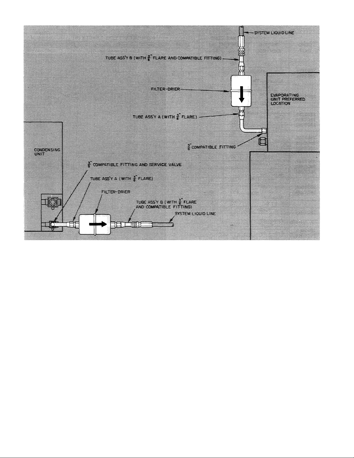
38CE045,005 AND 38CC UNITS - A filter-drier
package is shipped with these units. Included with
filter-drier are 2 short length tubing assemblies that
are equipped with flare and/or Compatible Fit
tings. Use tubing assemblies to install filter-drier
into system liquid line at evaporator or condensing
unit. See Fig. 2. Connect tubing assembly A (90°
assembly) to evaporator or condensing unit liquid
line Compatible Fitting. Complete the filter-drier
installation as shown.
Table 3 — Field-Supplied Piping Data
MAX COND
COND
X-
f 3 UNIT
38GS014,
38GS018
38GS024
38GS030,
38CC030,
38CE002
38GS036,
38CC036,
38CE003
38GS042,
38CC042,
38CE004
38GS048,
38CC048
38CE045
38GS06 0,
38CC060,
38CE005
Cap. Tube
TXV
NOTES
REFRIG
CONTROL
TXV
Cap. Tube
or
AccuRater'*'^
TXV
Cap. Tube
AccuRater
Cap. Tube
or
AccuRater
TXV
Cap. Tube
or
AccuRater
TXV
Cap Tube
or
AccuRater
TXV
Cap Tube
or
AccuRater
TXV
Cap. Tube
or
AccuRater
L^y
Cap. Tube
or
AccuRater
Crankcase heater and liquid line filter-drier required
on 38GS and 38CE units Accessory start capacitor
with relay also required on 38GS unit, but not
normally required on 38CE units See Compressor
Service Reduce liquid line diameter by 1/8-in OD
(min 1/4-in OD) when evaporator is 20 ft or more
below condensing unit
■ Capillary Tube
- Thermal Expansion Valve
1 The following system modifications are required adjust
refrigerant charge on systems with over 25 ft separation
UNIT HT (ft)
Above
Evap
90
150
yo
150
150
90
150
90
150
90 ■
150
90
150
90
150
Be low
Evap
90
50
90
50 %
__
50
90
50
90
50
90
50
90
50
90
50
25- 50 51» 7S 7&~ 1
Suet Liq
V
'8 V» 'x iiiiii lili
%
%
%
%
1%
IV»
Vs
V» T
V»
/4
% liM
% Iliiii
V»
REFRIGERANT LINE LENGTH (ft)
Line Diameter (in* OD)
'
IIBI
ilM
iiiiiiiiiii
wmmmmmmm
N s
T %
k
between condensing unit and evaporator (See Refrigerant
Charging ) Adjust system oil charge as described in Note 2
Oil charge adjustment add 1% of nominal oil charge in
system (Table 7) for each 10 ft of refrigerant line length
above 50 feet Eor example, a system that has a 50-oz oil
charge with 1 50 ft of interconnecting piping requires 5 oz of
additional oil as shown below:
V
iÄiii
MB
ISl
*
150 ft - 50 ft = 100 ft
100 ft -E 10 ft = 10 ft
Litj 1 LEíj
iiiiii
IH
■
ilBi %
■
11»
Äiii
10x1% = 10% ( 10)
10 X 50 oz = 5 oz
Do not permit condensing unit to short cycle, particularly on
applications with long vertical line lengths Correct short
cycling condition immediately
m
¡Mil
Í.
..............
Connection Procedure — When making tubing
connections, be sure to provide clearance at unit
for electrical connections.
Connect refrigerant liquid and suction lines to
condensing unit, Fig. 1. Unit Compatible Fittings
permit 2 methods of refrigerant line connection;
mechanical (quick connect) or sweat connection.
Make suction line connection first.
38CE045,005, 38GS060 AND 38CC060 UNITS Remove suction line adapter taped to compressor
suction line. Connect 3/4-in. end of adapter to unit
suction line Compatible Fitting. Sweat connect
refrigerant suction line to 1 1/8-in. end of adapter.
Connect liquid refrigerant line to unit.
MECHANICAL CONNECTION (Mate one set of
connections at a time.)
1. Loosen nut on Compatible Fitting one turn. Do
not remove.
Remove plug and be sure 0-ring is in the groove
2.
inside the Compatible Fitting.
Cut tubing to correct length.
3.
Use gage on tag attached to service valve to
4.
mark tube end for correct insertion depth.
Insert tube into Compatible Fitting until it
bottoms. (Tube should be inserted at least as
far as mark on tubing.)
Tighten nut until it bottoms on back coupling
5.
flange.
c
Fig. 2 — Filter-Drier Assembly Installation (38CC, 38CE045 and 005)
SWEAT CONNECTION (Use refrigerant grade
tubing.)
1. Remove locking nut, rubber 0-ring and
Schrader core from valve.
2. Cut tubing to correct length.
3. Insert tube into Compatible Fitting. Wrap top
and bottom of service valves in wet cloth to
prevent damage by heat. Solder with low
temperature (450 F) silver alloy solder.
4. Replace Schrader core.
5. Evacuate or purge system with field-supplied
refrigerant.
ELECTRICAL DATA AND WIRING
Field wiring must comply with local and
national fire, safety and electrical codes. Voltage to
unit must be within ± 10% of voltage indicated on
nameplate. Contact local power company for
correction of improper line voltage.
of ifolt ois tmpro|>er Ime
When making electrical connections, provide
clearance at unit for refrigerant piping connections.
See Table 4 for recommended wire and fuse sizes.
Install a Branch Circuit Fused Disconnect of
adequate size to handle unit starting current.
Locate disconnect within sight of and readily
accessible from the unit, per section 440-14 of
National Electrical Code (NEC).
Bring Line Power Leads Into Unit — Extend leads
from fused disconnect thru hole provided in service
embossment (Fig. 1) and thru 7/8-in. hole into
control box.
Connect Ground Lead to a Ground Lug in Control
Box for safety. Connect power wiring. See Fig. 3.
Splice line power leads to red and violet pigtails on
38GS,CE units or to yellow pigtails (3) on 38CC
units. Use wire nuts supplied with unit. Tape each
connection. Wire nuts are suitable for copper or
aluminum wire since they contain joint compound.
Control Power (24 v) wiring is brought thru hole in
service embossment and spliced to yellow pigtails
on all units. See Fig. 4.
Furnace or fan-coil transformer must be used as
24-v supply for system as shown in Fig. 4 (At least
a 40-va transformer is recommended.) Current
38GS048,060 and 38CC048,060 units are equip
ped with a low-voltage transformer used to power
contactor thru unit control circuit. This trans
former must not be used for powering the indoor
thermostat control circuit.
I-PHASE
CONN. TO
FUSED
DISCONNECT
3-PHASE
CONN. TO
FUSED
DISCONNECT
SPLICE
------------
FACTORY WIRING
------------
FIELD WIRING
p
—
--I3D GROUND LUG
386S,CEC0NDUNIT
-YEL-
-YEL-
-YEL-
-------I3D GROUND LUG
38CC CONO UNIT
Fig. 3 — Line Power Connections
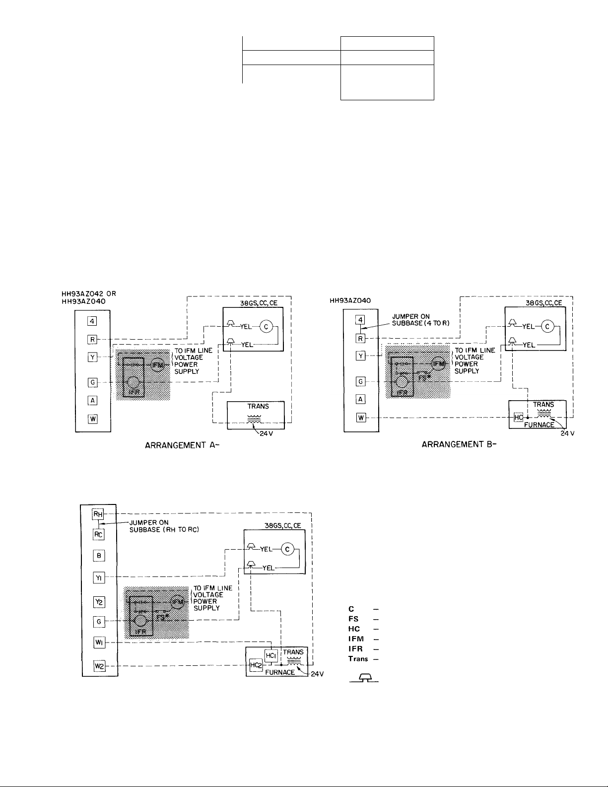
THERMOSTAT SUBBASE
THERMOSTAT SUBBASE
HH93AZ076
(COOLING ONLY)
THERMOSTAT SUBBASE
HH93AZ042 OR
ONE TRANSFORMER
(COOLING AND ONE-STAGE HEATING)
^CONNECT FS TO LOW-SPEED INDOOR FAN TERMINAL
WHEN 2-SPEED FAN IS USED
IFR, FS and IFM are located in furnace on heating-cooling
applications If accessory IFR is required for cooling only
applications, locate (IFR) in fan coiI
ARRANGEMENT C-
ONE TRANSFORMER
(COOLING AND 2-STAGE HEATING)
^CONNECT FS TO LOW-SPEED INDOOR FAN TERMINAL
WHEN 2-SPEED FAN IS USED
Fig. 4 -- Control Circuit Connections
Control Relay (10 va) or Contactor
Fan Switch
Heating Control
I ndoor Fan Motor
I ndoor Fan Relay
Transformer
Field Splice
---------------
Field Wiring
---------------- Factory Wiring
5
Loading...