


38E
Table of contents
 Loading...
38E,Q
HEATING & COOLING
Condensing Units and Heat Pumps
Service Manual
38EH,EN,ES,QH,QN,QS
TABLE OF CONTENTS
Page
INTRODUCTION
Models and SEER Ranges...................................... 1
Factory-Installed Options
SAFETY CONSIDERATIONS
SERVICE.................................................................... 3
Cabinet...................................................................... 3
• REMOVING LOUVERED CASING
• REMOVING FAN ORIFICE
• ELECTRICAL BOX ACCESS
Electrical
.................................................................
• CONTACTORS
• CAPACITORS
• TIME GUARD II
• CRANKCASE HEATER
• PRESSURE SWITCHES
• DEFROST THERMOSTATS ,
• PRINTED-CIRCUIT CONTROL BOARD
• FAN MOTORS
• SERVICE SENTRY CONTROL BOARD
• OUTDOOR THERMOSTATS
......................................................
.......................................
.......
............................
1,2
2
3
5-11
Compressor
......................... ..................................
• MECHANICAL FAILURES
• ELECTRICAL FAILURES
• SYSTEM CLEAN-UP AFTER BURN-OUT
• COMPRESSOR REMOVAL AND
REPLACEMENT
Refrigeration System
..........................................
15-20
• REFRIGERATION CYCLE
• LEAK DETECTING
• SERVICE VALVES
• CARRIER COMPATIBLE FITTING
• ACCURATER™ (Bypass type) COMPONENTS
• REVERSING VALVE
• COIL REMOVAL
• COIL CLEANING
• LIQUID LINE STRAINER
• ACCUMULATOR
• SYSTEM CHARGING (for all approved
combinations)
Page
12-15
INTRODUCTION
This Service Manual enables a service technician to
.service and repair a family of similar condensing units
and heat pumps. Outwardly, many models appear
Models and SEER Ranges
Table 1 — Condensing Units
MODEL
38EH015 22
38EH018 22
38EH024 22
38EH030 30
38EH036 30 9.0
38EH042 30 9,0
38EH048 30 9.0
38EH060
38EN015
38EN018
38EN024
38EN030 22
38EN036
38EN042 30 8.0
38EN048 30 8.0
38EN060
38ES018 30
38ES024
38ES030 30
38ES036
38ES042 30
38ES048 30
38ES060 39
’SEER — Seasonal Energy Efficiency Ratio. The higher the number, the
less electrical power required to reach a given capacity. SEER
is derived by dividing output energy by input energy.
DIAMETERS SEER*
(in.)
30
17
17
17
22
30 8.0
30 10.0
30
(Nominal)
9.0
9.0
9.0
9.0
9.0
8.0
8.0
8.0
8.0
8.0
10.0
10.0
10.0
10.0
10.0
10.0
similar, however, there are distinct differences. Tables 1
and 2 help to differentiate these differences.
Table 2 — Heat Pumps
MODEL
38QH015
38QH018
38QH024 30
38QH030 30
38QH036
38QH042 30
38QH048
38QH060 39
38QN015
38QN018
38QN024 22
38QN030
38QN036 30
38QN042 30
38QN048 30
38QN060 30
38QS018 30
38QS024
38QS030 30
38QS036 30
38QS042 30
38QS048
38QS060 39
tC.O.P. — Coefficient of Performance (heating), determined by dividing
DIAMETERS
(in.)
22
22
30
30
17
17
22
30
30
Btu output by power input required to producethis Btu output.
SEER*
(Nominal)
■ 9.0
9.0
9.0
9.0 2.85
9.0
9.0
9.0
9.0 2.85
8.0
8.0
8.0
8.0 2.55
8.0
8.0
8.0
8.0
10.0
10.0
10.0
10.0
10.0 2.85
10.0
10.0 2.85
CiO.P.t
(Minimum)
2.85
2.85
2.85
2.85
2.85
2.85
2.55
2.55
2.55
2.55
2.55
2.55
2.55
2.85
2.85
2.85
2.85
2.85
Manufacturer reserves the right to discontinue, or change at any time, specifications or designs without notice and without incurring obligations.
Book |l 1 |4 |4
Tab jsa
5a|2a|5a
PC 101
Catalog No. 563-857 Printed in U.S.A. Form 38E.Q-1SM
For replacement items use Carrier Specified Parts.
Pgi
11-85
Replaces; New
Factory-Installed Options — Any condensing unit
or heat pump listed in Tables 1 and 2 may be ordered as
Basic or in one of 3 factory-option packages. Package
designations are included in model number (excluding
Table 3 — Option Packages
Basic). Example: 38EN0243015A/. SM designates this
unit as sheet metal option package. Option package
designations are shown in Table 3.
Basic
Sheet Metal Option (SM)
Deluxe Option (DL)
Custom Deluxe Option (CD) Same unit as (DL) except for addition of
Basic
Sheet Metal Option (SM)
38EH,ES
Standard unit with no added options.
Same unit as Basic except with addition
of louvered inlet casing.
Same unit as (SM) except for addition ■
of start assist components on single
phase units, crankcase heater, highand low-pressure switches, and
accumulator.
sound shield around compressor, and
Time Guard II device.
38EN
Standard unit with no added options.
Same unit as Basic except for addition
of louvered inlet casing.
Table 4 — Condensing Unit Specifications
OUTDOOR
UNIT
MODEL NO.
38-
EH-
015301
018301
024301
030301
036301 AV5535E
042301 AV5542E
048321 AV5546H
060301
EN-
015310 AK8515E
018310
024310
030300
D30320
036320
042300
048300
060300
060310
030500
036500
042500
048500
060500 PY6716AF
060510 PY6716AF
036600
042600
048600 PH5316AD
060600
060610
ES018
024
030
036
042
048
060
ORIGINAL
COMPRESSOR
MODEL
REZ3-0125
AB5515H
MD2315GG
MD3215GG
PC6016BD
RES3-0175-PFV
H21B243ABC
H21A313ABCA
MD3215GG
H21A363ABCA
H21A463ABCA
PC5316BD
PC6716AG
PC6716AG
H21A313DBD
H21A373DBD
H21A463DBD
PY5316AD
H21A373DBE
A21A463DBE
PH6716AF
PH6716AF
AB5515H
CRC1-0175-PFV
H23A263ABCA
CRH3-0275-PFV
CRK3-0325-PFV
AV5546H
—
REPLACEMENT
COMPRESSOR
■ 38EN663304
38EN663601
PH6766HF
50SR661301 32
38VH660303
50SR661333 50
51HK660304
48GH 662302
50SR661331 54
Basic
Sheet Metal Option (SM) Same unit as Basic except for addition
Deluxe Option (DL)
Custom Deluxe Option (CD)
Basic
Sheet Metal Option (SM)
OIL CHARGE
MODEL
50QT662300
50SR661301 32
MD2364GE 46 44 5.6
MD3264GE 46 44
50SR661336
50SR661300
50SR661331 54
PC6066ED
51D2661300 17
38EA662301 24
38EN663307 40
38EN663302
MD3264GE
38EN663303 50
PC5366HD
PC6766HG 76
PC6766HG
38EN663501
38EN663502
38EN663500
See Note t
See Note t
See Note $
38 EN 663600
PH5366HD
PH6766HF
—
Initial Recharge
24
54
54
76 72 '12.7
40 37
46
50
76 .
76
40
50
50
76
76
76
50
50
76
76
76
55
55
55
38QH,QS
Standard unit with no added options.
of louvered inlet casing.
Same unit as (SM) except for addition
of start assist components on single
phase units, high-pressu.re switch, and
Service Sentry device.
Same unit as (DL) except for addition
of sound shield around compressor and
Time Guard II device.
38QN
Standard unit with no added options.
Same unit as Basic, except for addition
of louvered inlet casing.
REFRIG
CHARGE*
(R-22)
20 ■ ■ 6.2
30
50
50
50
15 ,3.2
20 3.7
37 3.8
44
47
47 7.2
72
72 9.5
72
37
47
47 7.2
72
72 9.6
72
47 .
47 7.2
72 7.6
72 9.6
72 12.5
28 7.20
51 7.40
46 6.50
51 7.50
51 7.80
50 12.50
. 6.7
12.5
12.5
7.1
5.6
5.8'
7.6
5.5
5.8
7.6
5.8
6.3
7.3
7.4
8.9
’Factory refrigerant charge is adequate when indoor unit and outdoor unit are the same size
and are connected with 25 ft or less of field tubing of recommended size or Carrier accessory
tubing. For tubing requirements beyond 50ft, consult Carrier distributor.
H-R
NOTE: Originally an extended voltage compressor.
Select replacement compressor for voltage required:
tPF5366HD (200-3-60), PG5366HD (230-3-60).
tPF6766HF (200-3-60), PG6766HF (230-3-60).
Table 5 — Heat Pump Specifications
OUTDOOR
UNIT
MODEL NO.
38QH
015
018
024
030
036
042 .
048
060
060341
030
036
042
048
060
036
042
048
060
ON
015
018
024
030
036
042
048
060
036
042
048
060
036
042
048
060
QS
018
024
030
036
042
'Factory refrigerant charge is adequate when indoor unit and outdoor unit are the same
size and are connected with 25ft or less of field tubing of recommended size orCarrier
accessory tubing. For tubing requirements beyond 50ft, consult Carrier distributor.
ORIGINAL
COMPRESSOR
MODEL
REZ3-0125-PFV
H22B173ABCA
CRC2-0175-PFV
AV5532E 50SR661333
AV5535H 50SR661336
AV5542H 50SR661330
AV5546H
WD60000AA WD6051AA 76
H23A563ABCA
AV5532E 50SR661415
AV5535E 50SR661413
AV5542E
AV5546E 50SR661500
WY6000AA WY6051AA 76
AV5535E 50SR661623
AV5542E
AV5546E
WH6000AA WH6051AA 76
REZ3-0125-PFV
AB5519H
MD2315GG MD2364GE
MD3215GG
MD3515GG
AV5542E 50SR661330
PC5316BD PC5366HD
PC6016BD
MF3513GB
AV5542E
PY5316AD See Note t
PY6016BD
MH3513GB
PH4616AD
PH5316AD PH5366HD
PH6016BD
AB5515H 50SR661301 32
JD2200AA JD2251AA 50
JD2800AA
JD3300AA JD3300AA 50
CRJ3-0300-PFV 38EB660301 55
REPLACEMENT
COMPRESSOR
MODEL
50QT662300
38QF663300
38VH 660303
50SR661331
—
50SR661414 54
50SR661624 54
50SR661622
38QB662301
50SR661311
MD3264GE 46
MD3564GE 46
PC6066ED 76
MF3563GE 46
50SR661330
PY6066EF 76
MH3563GE 46
PH4666HD 76
PH6066EF 76
JD2851AA
OIL CHARGE
Initial
24 20
40
55
54 50
54 50
54 50
54 50
55
54 50
54
54 50
54
54 50
24
32
46
54
76
54
76
76
50
NOTE: Originally an extended voltage compressor.
Select replacement compressor forvoltage-required:
tPF5366HD (200-3-60), PG5366HD (230-3-60).
Recharge
37
52
74
50
50 7.9
50
74 14.1
50
50
74
20
28
44 5.6
44 6.1 . ,
44 8.9
50 9.5
72
72
44 8.9
50
72
72
44 8.9
72
72
72
28
46
46
46
51
REFRIG
CHARGE*
(R-22)
5.3
5.5
7.8
7.8
7.9
11.0
12.5
14.1
14.0
7.8
11.0
12.5
7.9
11.0
12.5
14.1
3.6
4.1
9.7
10.8
9.5
9.7
10.8
9.5
9.7
10.8
6.8
7.5
8.5
10.6
11.5
SAFETY CONSIDERATIONS
Service and repair of these units should be attempted
only by trained service technicians familiar with Carrier
Standard Service Instructions.
All equipment should be installed in accordance with
accepted practices and in compliance with all national
and local codes.
Power should be turned off when servicing or repair
ing electrical components. Extreme caution should be
observed when troubleshooting electrical components
with power on. Observe all warning notices posted on
equipment.
Refrigeration system contains refrigerant under
pressure. Extreme caution should be observed when
handling refrigerants. Wear safety glasses and gloves to
prevent personal injury. During normal system opera
tion, some components are hot and can cause burns.
Rotating fan blades can cause personal injury. Appro
priate safety considerations are posted throughout this
manual where potentially dangerous techniques are
addressed.
SERVICE
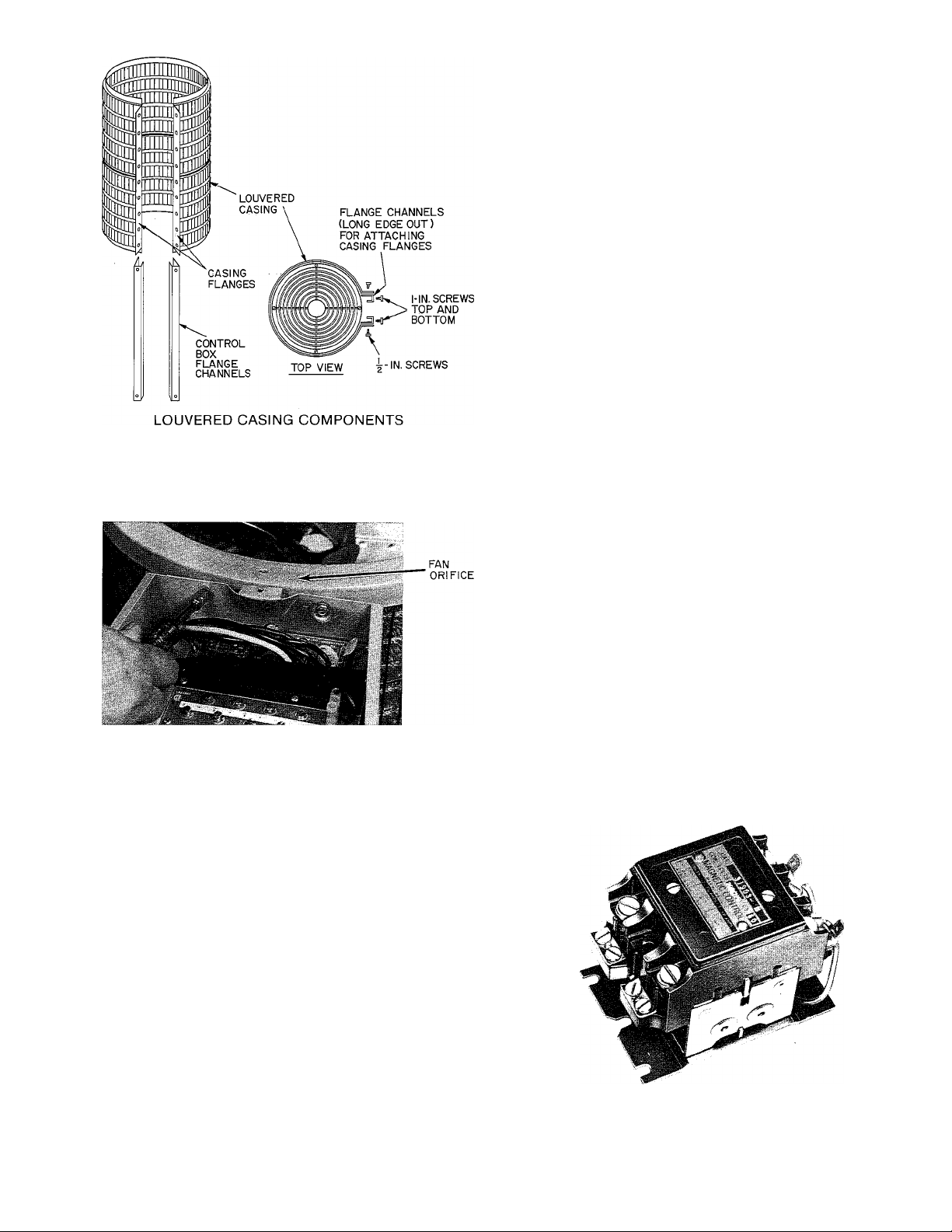
Cabinet — Certain maintenance routines and repairs
require removal of cabinet panels. All condensing units
and heat pump models of this series have same basic
design with only minor differences. See Fig. 1.
REMOVING LOUVERED CASING — (See Fig. 2.)
1. Turn off all power to unit.
2. Loosen screws around circumference of fan orifice.
3. Remove screws around circumference of basepan.
4. Remove screws along control box support brackets.
5. Carefully remove louvered casing.
A CAUTION
Do not attempt to remove wire grille around coil.
Grille is integral part of coil structure and sup
ports coil.
REMOVING FAN ORIFICE — (See Fig. 3.)
1. Turn off all power to unit.
2. Remove screws holding grille on top of fan orifice.
3. Unplug wires from fan motor. Fan blades on certain
models may have to be removed. Refer to Service —
Electrical.
4. Remove screws holding fan orifice to wire grille and
control box.
5. Remove fan orifice.
ELECTRICAL BOX ACCESS — (See Fig. 1.)
1. Turn off all power to unit.
2. Remove screws holding box cover.
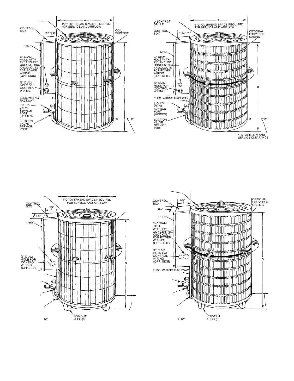
DISCHARGE
GRILLE
BASIC CONDENSING UNIT
r-6" AIRFLOW AND
SERVICE CLEARANCE
ON 3 SIDES — 12" ON
REMAINING SIDE
ON 3 SIDES — 12" ON
REMAINING SIDE
LOUVERED CONDENSING UNIT
DISCHARGE
GRILLE
IVb" DIAM
HOLE
WITH 1%"
CONCENTRIC
KNOCKOUT
FOR POWER
WIRING
(OPP. SIDE)
ELEC. WIRING RACEWAY
LIQUID LINE
SERVICE PORT
ATSERVlOE
VALVE(CLG
CYCLE)
SUCTION
SERVICE PORT
AT SERVICE
VALVE(CLG
CYCLE)
SUCTION
SERVICE PORT
(HIDDEN)
COIL
SUPPORT
r-6" AIRFLOW AND
SERVICE CLEARANCE
ON 3 SIDES — 12" ON
REMAINING SIDE
DISCHARGE
GRILLE
LIQUID LINE
SERVICE PORT
AT SERVICEVALVE (CLG
CYCLE)
SUCTION
SERVICE POR
AT SERVICE
VALVE(CLG
CYCLE)
SUCTION
SERVICE PORT
(HIDDEN)
4'-0” OVERHEAD SPACE REQUIRED
FOR SERVICE AND AIRFLOW
r-6" AIRFLOW AND
SERVICE CLEARANCE
ON 3 SIDES —12" ON
REMAINING SIDE
BASIC HEAT PUMP UNIT
Fig. 1 — Condensing and Heat Pump Units
LOUVERED HEAT PUMP UNIT
SCREWS
TOP COVER
BASEPAN FLANGE
C
Fig. 2 — Louvered Casing Assembly
Fig. 3 — Removing Orifice Fan
Electrical — Exercise extreme caution when work
ing on any electrical components. Shut off all power
to system prior to troubleshooting. Some trouble
shooting techniques require power to remain on. In
these instances, exercise extreme caution to avoid
danger of electrical shock. ONLY TRAINED SERVICE
PERSONNEL SHOULD PERFORM ELECTRICAL
TROUBLESHOOTING.
CONTACTORS — (See Fig. 4.) Contactor provides
means of applying power to unit using lower power
(24 v) from transformer in order to power the contactor
coil. Depending on unit model, you may encounter
single-, double- or triple-pole contactors to break power.
One side of the line may be electrically hot, so extreme
caution must be exercised when troubleshooting.
The contactor coil for these and most residential
models of condensing units and heat pumps is powered by
24 vac. If contactor does not operate:
1. With power off, check whether contacts are free to
move. Check for severe burning or arcing on contact
points.
ATTACHING CASING TO TOP COVER
AND BASEPAN
2. With power off, use ohmmeter to check for continuity
of coil. Disconnect leads before checking. A lowresistance reading is normal. Do not look for a specific
value as different part numbers used will have different
resistance values.
3. Reconnect leads and apply low-voltage power to
contactor coil. This may be done by leaving highvoltage power to outdoor unit off, and by turning
thermostat to heat or cool. Check voltage at coil with
voltmeter. Reading should be between 20 - 30 volts.
Contactor should pull in if voltage is correct and coil
is good. If contactor does not pull in, change
contactor.
4. With high-voltage power off and contacts pulled in,
check for continuity across contacts with ohmmeter.
A very low or zero resistance should be read. Higher
readings could indicate burned or pitted contacts
which may cause future failures.
Fig. 4 — Contactor
CAPACITORS — (See Fig. 5.)
A CAUTION
Capacitors can store electrical energy when power
is off. Electrical shock can result if you touch the
capacitor terminals and discharge this stored energy.
Exercise extreme caution when working near
capacitors. With power off, discharge stored energy
by shorting across the capacitor terminals with a
15,000-ohm, 2-watt resistor, or a screwdriver blade
with insulated handle.
Hard-Start Capacitors and PTC Devices — Sometimes,
under adverse conditions, a standard run capacitor in a
system is inadequate to start compressor. In these
instances, a start-assist device is used to provide an extra
starting boost to compressor motor. The first device is
called a PTC (positive temperature coefficient) or ther
mistor (see Fig. 6). It is a resistor wired in parallel with run
capacitor. As current flows through it at start-up, it heats
up. As it heats up, its resistance increases greatly, until
it effectively lowers current through it to an extremely
low value. This, in effect, removes it from the circuit.
After system shuts down, resistor cools and resistance
value returns to normal, until next time system starts.
Thermistor device is adequate for most conditions,
however, in systems where off cycle is short, device
cannot cool fully and becomes less effective as a start
device. It is an easy device to troubleshoot. Turn off all
power to system.
Check thermistor with ohmmeter as described below.
If indoor coil does not have a bleed-type expansion
device, it may be necessary to remove start thermistor
and replace with accessory start capacitor and relay.
Shut off all power to unit. Remove PTC from unit.
Wait at least 10 minutes for PTC to cool to ambient
temperature.
RUN CAPACITOR START CAPACITOR
Fig. 5 — Capacitors
Capacitors are used as a phase shifting device to aid in
starting certain single-phase motors. Check capacitors
as follows:
1. Always check capacitors with power off. Attempting
to troubleshoot a capacitor with power on can be
dangerous. Defective capacitors may explode when
power is applied. Insulating fluid inside is combustible
and may ignite, causing burns. After power is off,
discharge capacitors as outlined above. Disconnect
capacitor from circuit. Use ohmmeter, check each
terminal to ground (use capacitor case). Discard any
capacitor that shows resistance. Place ohmmeter leads
across capacitor and place on R x 10k scale. Meter
should jump to a low resistance value and slowly climb
to higher value. Eailure of meter to do this indicates
an open capacitor. If resistance stays at zero or a low
value, capacitor is shorted.
2. Capacitance testers are available which will read value
of capacitor. If value is not within ± 10% value stated
on capacitor, it should be changed. If capacitor is
not open or shorted, its capacitance value is calcu
lated by measuring voltage across capacitor and
current it draws.
A WARNING
Exercise extreme caution when taking readings
while power is on. Use following formula to
calculate capacitance:
^ . , r,. 2650 X amps
Capacitance (mfd) =
3. Remove any capacitor that shows signs of bulging,
dents or leaking. Do not apply power to a defective
capacitor as it may explode.
volts
Measure resistance of PTC with ohmmeter. Resistance
of 25-ohm PTC is measured between center tab and
end tab with jumper across 2 end terminals.
Fig. 6 — PTC Devices
The cold resistance (Rj) of any PTC device should be
approximately 100 - 180% of device ohm rating.
50-ohm PTC = 50 - 90 ohm resistance
25-ohm PTC = 25 - 45 ohm resistance
If PTC resistance is appreciably lower or more than
200% higher than rating, device is defective.
If thermistor is good and compressor does not start,
disconnect thermistor from starting circuit. Give com
pressor a temporary capacitance boost. Run compressor
for 10 minutes, shut off, allow system pressure to equal
ize. Reconnect start thermistor. Try restarting com
pressor without boost capacitor. If after 2 attempts,
compressor does not start, remove thermistor. Add an
accessory start capacitor relay package.
Temporary Capacitance Boost — (See Fig. 7.) There are
times when a temporary capacitance boost is needed to
get compressor started. Do not under any circumstances
attach temporary boost capacitor directly across com
pressor terminals. Serious personal injury can result.
Exercise extreme caution with this procedure when highvoltage power is on. If compressor motor does not start,
it may be due to low-line voltage, improper pressure
equalization or weak run capacitor. Check each possi
bility, attempt capacitance boosting before adding
auxiliary start capacitor and relay.
Loading...