


38AQS008 Air-Cooled Split System Heat Pump 50/60 Hz
Installation, Start-Up and
Service Instructions
CONTENTS
Page
SAFETY CONSIDERATIONS . . . . . . . . . . . . . . . . . 1
INSTALLATION . . . . . . . . . . . . . . . . . . . . . . . . . . . . 1-9
Step 1 — Complete Pre-Installation Checks . . 1
•UNCRATE UNIT
•INSPECT SHIPMENT
•CONSIDER SYSTEM REQUIREMENTS
Step 2 — Rig and Mount the Unit . . . . . . . . . . . . 2
•RIGGING
•MOUNTING
•COMPRESSOR MOUNTING
Step 3 — Complete Refrigerant Piping
Connections . . . . . . . . . . . . . . . . . . . . . . . . . . . . . 2
•SIZE REFRIGERANT LINES
•FILTER DRIER AND MOISTURE INDICATOR
•LIQUID LINE SOLENOID VALVE
•SAFETY RELIEF
•SUCTION PIPING AT INDOOR COIL AND TXV SENSING BULB LOCATION
Step 4 — Make Electrical Connections . . . . . . . 3
•FIELD POWER SUPPLY
•ACCESSORY ELECTRIC HEAT
•FIELD CONTROL WIRING
START-UP . . . . . . . . . . . . . . . . . . . . . . . . . . . . . . . 10,11
Preliminary Checks . . . . . . . . . . . . . . . . . . . . . . . . 10
Evacuate and Dehydrate . . . . . . . . . . . . . . . . . . . 10
Refrigerant Charge . . . . . . . . . . . . . . . . . . . . . . . . 10
Refrigerant Service Ports . . . . . . . . . . . . . . . . . . 10
Sequence of Operation . . . . . . . . . . . . . . . . . . . . 10
Checking Cooling and Heating Control
Operation . . . . . . . . . . . . . . . . . . . . . . . . . . . . . . . 11
Malfunction . . . . . . . . . . . . . . . . . . . . . . . . . . . . . . . 11
SERVICE . . . . . . . . . . . . . . . . . . . . . . . . . . . . . . . . . 11-13
Cleaning . . . . . . . . . . . . . . . . . . . . . . . . . . . . . . . . . . 11
Lubrication . . . . . . . . . . . . . . . . . . . . . . . . . . . . . . . . 11
Outdoor-Fan Adjustment . . . . . . . . . . . . . . . . . . . 11
Compressor Removal . . . . . . . . . . . . . . . . . . . . . . 11
Cooling Mode Operation . . . . . . . . . . . . . . . . . . . 12
Heating Mode Operation . . . . . . . . . . . . . . . . . . . 12
TROUBLESHOOTING CHART . . . . . . . . . . . . . . 14,15
START-UP CHECKLIST . . . . . . . . . . . . . . . . CL-1,CL-2
SAFETY CONSIDERATIONS
Installing and servicing air-conditioning equipment can be hazardous due to system pressure and electrical components. Only trained and qualified service personnel should install or service air-conditioning equipment.
When working on air-conditioning equipment, observe precautions in literature and on tags and labels attached to unit.
Follow all safety codes. Wear safety glasses and work gloves. Use quenching cloth for brazing operations. Have fire extinguisher available. Read these instructions thoroughly. Consult local building codes and National Electrical Code U.S.A. (NEC) for special installation requirements.
Before installing or servicing system, always turn off main power to system. There may be more than one disconnect switch. Electrical shock can cause personal injury.
INSTALLATION
The 38AQS008 unit uses a semi-hermetic compressor. See Tables 1A and 1B for physical data.
The 38AQS008 is approved by Carrier for use only with 40RMQ008 fan cooling units. Use only approved far coils.
The 38AQS008 (60 Hz) is Underwriters’ Laboratories (UL) and Canadian Underwriters’ Laboratories (CUL) approved for use with the 40RMQ008 fan coil only.
Step 1 — Complete Pre-Installation Checks
UNCRATE UNIT (See Fig. 1) — Remove unit packaging except for the top skid assembly and wood bumpers, which should be left in place until after unit is rigged into place.
INSPECT SHIPMENT — File claim with shipping company if shipment is damaged or incomplete.
Fig. 1 — 38AQS008 Unit
Manufacturer reserves the right to discontinue, or change at any time, specifications or designs without notice and without incurring obligations.
Book |
1 |
4 |
|
PC 111 |
Catalog No. 533-887 |
Printed in U.S.A. |
Form 38AQS-4SI |
Pg 1 |
6-95 |
Replaces: 38AQS-3SI |
Tab |
5a |
5a |
|
|
|
|
|
|
|
|
|
|
|
|
|
|
|
|
|
|
|
Table 1A — Physical Data (English)
UNIT 38AQS008 |
60 Hz |
|
50 Hz |
OPERATING WEIGHT (lb) |
|
|
|
Aluminum Coils (Standard) |
540 |
|
594 |
Copper Coils (Optional) |
608 |
|
662 |
RIGGING WEIGHT (lb) |
|
|
|
Aluminum Coils (Standard) |
590 |
|
644 |
Copper Coils (Optional) |
658 |
|
712 |
REFRIGERANT* |
R-22 |
||
COMPRESSOR |
Reciprocating, Semi-Hermetic |
||
Quantity...Type |
1...06DA818 |
|
1...06DA824 |
Quantity Cylinders |
4 |
|
6 |
Speed (rpm) |
1750 |
|
1460 |
Oil Charge (oz) (ea) |
88 |
|
128 |
OUTDOOR FAN |
Propeller; Direct Drive |
||
Quantity...rpm |
1...1100 |
|
1...960 |
Diameter (in.) |
26 |
|
26 |
Motor Hp (NEMA) |
3Ú4 |
|
1Ú3 |
Nominal Airflow (cfm) |
6500 |
|
6100 |
OUTDOOR COIL |
Enhanced Copper Tubes, |
||
Face Area (sq ft) |
Aluminum Lanced Fins |
||
18.0 |
|||
Storage Capacity (lb)† |
16.56 |
||
Fins/in. |
17.0 |
||
Rows (No.) |
|
2 |
|
CONNECTIONS (Sweat) |
|
|
|
Suction (in.) |
|
11Ú8 |
|
Liquid (in.) |
|
1Ú2 |
|
CONTROLS |
|
|
|
Pressurestat Settings (psig) |
|
|
|
High Cutout |
426 7 |
||
Cut-in |
320 20 |
||
Low Cutout |
7 3 |
||
Cut-in |
22 5 |
||
Defrost Thermostat |
|
|
|
Initiate Defrost (F) |
|
28 |
|
Terminates Defrost (F) |
|
65 |
|
LEGEND
NEMA — National Electrical Manufacturing Association (U.S.A.)
*Unit is factory supplied with holding charge only.
Storage capacity of coil with coil 80% full of liquid R-22 at 120 F.
CONSIDER SYSTEM REQUIREMENTS
•Consult local building codes and NEC (U.S.A.) for special installation requirements.
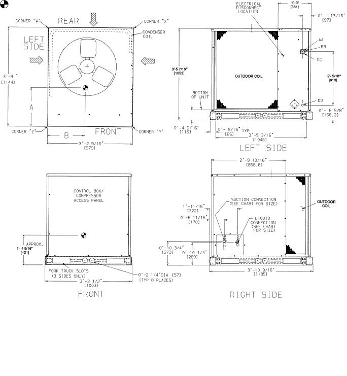
•Allow sufficient space for airflow clearance, wiring, refrigerant piping, and servicing unit. See Fig. 2.
•Locate unit so that outdoor unit airflow is unrestricted on all sides and above. Refer to Fig. 2.
•Unit may be mounted on a level pad directly on base rails or mounted on raised pads at support points. See Fig. 2 for weight distribution based on recommended support points.
•Provide for condensate drainage and defrost water disposal beneath unit.
•Areas with high snowfall may need elevated mounting for adequate airflow.
NOTE: If vibration isolators are required for a particular installation, use corner weight information in Fig. 2 to make proper selection.
Step 2 — Rig and Mount the Unit
Be sure unit panels are securely in place prior to rigging.
RIGGING — These units are designed for overhead rigging. Refer to rigging label for preferred rigging method. Spreader bars are not required if top crating is left on unit. All panels must be in place when rigging. (See Fig. 3.) As
Table 1B — Physical Data (SI)
UNIT 38AQS008 |
60 Hz |
|
50 Hz |
OPERATING WEIGHT (kg) |
|
|
|
Aluminum Coils (Standard) |
245 |
|
270 |
Copper Coils (Optional) |
276 |
|
299 |
RIGGING WEIGHT (kg) |
|
|
|
Aluminum Coils (Standard) |
268 |
|
292 |
Copper Coils (Optional) |
298 |
|
323 |
REFRIGERANT* |
R-22 |
||
COMPRESSOR |
Reciprocating. Semi-Hermetic |
||
Quantity...Type |
1...06DA818 |
|
1...06DA824 |
Quantity Cylinders |
4 |
|
6 |
Speed (r/s) |
29.2 |
|
24.2 |
Oil Charge (L) (ea) |
2.60 |
|
3.78 |
OUTDOOR FAN |
Propeller; Direct Drive |
||
Quantity...r/s |
1...18.3 |
|
1...16.0 |
Diameter (mm) |
660 |
|
660 |
Motor Hp (NEMA) |
3Ú4 |
|
1Ú3 |
Nominal Airflow (L/s) |
3070 |
|
2900 |
OUTDOOR COIL |
Enhanced Copper Tubes, |
||
Face Area (m2) |
Aluminum Lanced Fins |
||
1.67 |
|||
Storage Capacity (kg)† |
|
7.5 |
|
Fins/m |
|
669 |
|
Rows (No.) |
|
2 |
|
CONNECTIONS (Sweat)** |
|
|
|
Suction (in.) |
|
11Ú8 |
|
Liquid (in.) |
|
1Ú2 |
|
CONTROLS |
|
|
|
Pressurestat Settings (kPa) |
|
|
|
High Cutout |
2937 48 |
||
Cut-in |
2206 138 |
||
Low Cutout |
48 20 |
||
Cut-in |
151 34 |
||
Defrost Thermostat |
|
|
|
Initiate Defrost (C) |
−2.2 |
||
Terminates Defrost (C) |
|
18.3 |
|
LEGEND
NEMA — National Electrical Manufacturing Association (U.S.A.) *Unit is factory supplied with holding charge only.
Storage capacity of coil with coil 80% full of liquid R-22 at 49 C. **All pipe sizes are OD inches; equivalent sizes in millimeters follow:
in. mm
1Ú2 |
12.7 |
11Ú8 |
28.6 |
further protection for coil faces, plywood sheets may be placed against sides of unit, behind cables. Run cables to a central suspension point so that angle from the horizontal plane is not less than 45 degrees. Raise and set unit down carefully.
If it is necessary to roll unit into position, mount unit on rails, using a minimum of 3 rollers. Apply force to rails, not unit. If unit is to be skidded into position, place it on a large pad and drag it by the pad. Do not apply any force to unit.
Raise from above to lift unit from rails or pad when unit is in final position.
After unit is in position, remove all shipping wrapping and top crating.
MOUNTING — The unit must be elevated to ensure drainage from basepan during sub-freezing conditions and to prevent or limit blockage of outdoor coil during snowfall. Consideration should be given to specific geographical areas when determining height of unit elevation.
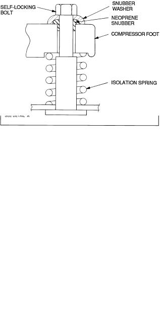
COMPRESSOR MOUNTING — As shipped, compressors are held down by 4 bolts. After unit is installed, loosen each bolt until the snubber washer can be moved with finger pressure. See Fig. 4.
Step 3 — Complete Refrigerant Piping Connec-
tions — Suction connection is sweat with plastic cap; liquid connection is sweat with plastic cap. Refer to Table 2 for the proper line sizes. Follow standard piping practices.
2
Table 2 — Refrigerant Piping Sizes
|
|
LINEAR LENGTH OF PIPING — ft (m) |
|
||||||||||
|
|
0-25 |
|
25-50 |
|
|
50-75 |
|
75-100 |
||||
|
UNIT |
(0-7.6) |
(7.6-15.2) |
|
(15.2-22.9) |
|
(22.9-30.5) |
||||||
|
38AQS |
|
|
|
|
Line Size (in. OD) |
|
|
|
||||
→ |
|
L |
S |
L |
|
S |
|
L |
|
S |
|
L |
S |
008 |
1Ú2 |
11Ú8 |
5Ú8 |
11Ú8 |
|
5Ú8 |
|
11Ú8 |
|
5Ú8 |
11Ú8 |
||
|
|
|
|
|
|
LEGEND |
|
|
|
|
|
|
|
|
L — Liquid Line OD — Outside Diameter |
S — Suction Line |
|||||||||||
NOTES:
1.Pipe sizes are based on a 2¡ F (1¡ C) loss for liquid and suction lines.
2.Pipe sizes are based on the maximum linear length shown for each column, plus a 50% allowance for Þttings.
3.Charge units with R-22 in accordance with unit installation instructions.
4.Line size conversion to mm is:
in. |
|
mm |
1Ú2 |
12.7 |
|
5Ú8 |
15.9 |
|
3Ú4 |
19 |
|
11Ú8 |
28.6 |
|
13Ú8 |
34.9 |
|
SIZE REFRIGERANT LINES — Consider length of piping required between 38AQS unit and 40RMQ unit, amount of liquid lift, and compressor oil return. See Table 3 and also refer to Part 3 of Carrier System Design Manual for design details and line sizing. Refer to 40RMQ installation instructions for additional information.
Table 3 — Liquid Line Data
|
|
|
MAX |
|
|
|
|
|
|
|
|
ALLOWABLE |
|
LIQUID LINE |
|
||||
UNIT |
|
|
LIQUID LIFT |
|
|
|
|
||
38AQS |
Heating |
Cooling |
Max Allowable |
Max Allowable |
|||||
|
Pressure Drop |
Temp Loss |
|||||||
|
|
|
|
|
|
||||
|
ft |
|
m |
ft |
m |
psi |
kPa |
F |
C |
008 |
75 |
|
22.9 |
65 |
19.8 |
7 |
48 |
2 |
1 |
1.The liquid lift in cooling mode is based on 80/67 F (22.7/19.4 C) (db/wb [dry bulb/wet bulb]) entering indoor-air temperature and a 95 F (35 C) outdoor-air temperature, with R-22 refrigerant, at an indoor airßow of 3000 cfm (1416 L/s).
2.The liquid lift in heating mode is based on 70/60 F (21.1/15.6 C) (db/wb) entering indoor-air temperature and a 47/43 F (8.3/6.1 C) (db/wb) outdoor-air temperature, with R-22 refrigerant, at an indoor airßow of 3000 cfm (1416 L/s).
FILTER DRIER AND MOISTURE INDICATOR — See Fig. 5. The filter drier is factory supplied and field-installed in the liquid line. Moisture indicator is field-supplied and should be installed just after liquid line shutoff valve. Do not use a receiver; there is none provided with unit and one should not be used.
NOTE: Unit is shipped with R-22 holding charge. System pressure must be relieved before removing caps. Recover refrigerant prior to brazing.
Pass nitrogen or other inert gas through piping while brazing to prevent formation of copper oxide.
LIQUID LINE SOLENOID VALVE — A field supplied liquid line solenoid valve (LLSV) is recommended when piping system length exceeds 75 ft (23 m). The LLSV must be of the biflow type, suited for use in heat pump systems.
NOTE: Carrier recommends part number EF23JS214 (Sporlan model CB14S2, 5⁄8-in. ODF/7⁄8-in. ODM) available from the Replacement Components Division of Carrier Corporation. This solenoid requires field supplied Sporlan MKC-2 coils.
Wire the solenoid in parallel with the compressor contactor coil.
Install the LLSV near the outdoor unit. The flow arrow must be pointed toward the outdoor unit.
SAFETY RELIEF — A fusible plug is located on top of the accumulator. See Fig. 6. Note that all safety relief components are factory installed. Do not cap fusible plug. If local code requires additional safety device(s), install as directed.
SUCTION PIPING AT INDOOR COIL AND TXV SENSING BULB LOCATION — To achieve good mixing of refrigerant leaving the indoor coil suction header for proper sensing by the thermostatic expansion valve (TXV) bulb (see Fig. 7):
1.A minimum of two 90-degree elbows should be installed upstream of the TXV bulb location.
2.The TXV bulb should be located on a vertical riser where
possible. If a horizontal location is necessary, secure the bulb at approximately the 4 o’clock position or the 8 o’clock position. See Fig. 7.
3.Enter suction pipe sizing charts in the Carrier System Design Manual at design tons and equivalent length for 2° F (1° C) loss. If the reading falls between 2 sizes on the chart, choose the smaller pipe size.
4.Make sure that the piping system has no inherent oil traps, and the piping layout will not allow oil to migrate into an idle evaporator coil.
5.Complete refrigerant piping from indoor coil to outdoor coil before opening liquid and suction lines at the 38AQS unit. See Tables 1A, 1B, and 2 for piping selection data.
Step 4 — Make Electrical Connections
Unit cabinet must have an uninterrupted, unbroken electrical ground to minimize the possibility of personal injury if an electrical fault should occur. This ground may consist of electrical wire connected to unit ground lug in control compartment, or conduit approved for electrical ground when installed in accordance with NEC ANSI (American National Standards Institute, U.S.A.)/ NFPA (National Fire Protection Association, U.S.A.) 70 and local electrical codes. Failure to follow this warning could result in the installer being liable for personal injury of others.
FIELD POWER SUPPLY — All units except 208/230-v (60 Hz) units are factory wired for the voltage shown on the nameplate. If the 208/230-v unit is to be connected to a 208-v power supply, the transformer must be rewired by moving the black wire from the 230-v orange wire on the transformer and connecting it to the 208-v red wire from the transformer. The end of the orange wire must then be insulated.
Refer to unit label diagram for additional information. Short wire leads (pigtails) are provided for field wire connections. Use factory-supplied splices or UL approved copper/ aluminum connector.
When installing units, provide a disconnect per NEC (U.S.A.).
399 |
3 |
UNIT |
UNIT |
UNIT |
|
WEIGHT CHART (WITH ALUMINUM COIL) |
|
|
WEIGHT CHART (WITH COPPER COIL) |
|
|||||||||||||||||
W/ALUMINUM COIL |
W/COPPER COIL |
Std Unit |
Corner W |
Corner X |
Corner Y |
Corner Z |
Std Unit |
Corner W |
Corner X |
Corner Y |
Corner Z |
||||||||||||||
38AQS008 |
|
|
|
|
|
|
|
|
|
|
|
|
|
|
|
|
|
|
|
|
|
|
|
|
|
Dim. A |
Dim. B |
Dim. A |
Dim. B |
Lb |
Kg |
Lb |
Kg |
Lb |
Kg |
Lb |
Kg |
Lb |
Kg |
Lb |
Kg |
Lb |
Kg |
Lb |
Kg |
Lb |
Kg |
Lb |
Kg |
||
|
|||||||||||||||||||||||||
60 Hz |
1 -8 |
1 -5 |
1 -91Ú2 |
1 -43Ú4 |
540 |
245 |
132 |
60 |
100 |
45 |
133 |
60 |
175 |
80 |
608 |
276 |
160 |
73 |
117 |
53 |
142 |
64 |
189 |
86 |
|
|
[508.0] |
[431.8] |
[546.0] |
[425] |
|
|
|
|
|
|
|
|
|
|
|
|
|
|
|
|
|
|
|
|
|
50 Hz |
1 -6 |
1 -7 |
1 -71Ú2 |
1 -63Ú4 |
594 |
270 |
114 |
52 |
114 |
52 |
183 |
83 |
183 |
83 |
662 |
299 |
142 |
64 |
131 |
59 |
192 |
87 |
197 |
89 |
|
|
[457.2] |
[482.6] |
[495.3] |
[476.3] |
|
|
|
|
|
|
|
|
|
|
|
|
|
|
|
|
|
|
|
|
|
NOTES:
1. Dimensions in [ ] are in millimeters.
2. Center of Gravity. See chart for dimensions.
3. Direction of airßow.
4.Minimum clearance (local codes or jurisdiction may prevail):
a.Bottom to combustible surfaces, 0 in. (0 mm)
b.Outdoor coil, for proper airßow, 36 in. (914 mm) one side, 12 in. (305 mm) the other. The side getting the greater clearance is optional.
c.Overhead, 60 in. (1524 mm) to assure proper outdoor-fan operation.
d.Between units, control box side, 42 in. (1067 mm) per National Electrical Code (NEC, U.S.A.).
e.Between unit and ungrounded surfaces, control box side, 36 in. (914 mm) per NEC (U.S.A.).
f.Between unit and block or concrete walls and other grounded surfaces, control box side, 42 in. (1067 mm) per NEC (U.S.A.).
5.With the exception of the clearance for the outdoor coil as stated in note 4b, a removable fence or barricade requires no clearance.
6.Units may be installed on combustible ßoors made from wood or Class A, B, or C roof covering material.
7.Vertical center of gravity is approximately 40% of total unit height.
|
ELECTRICAL CONNECTIONS |
|
||
|
|
|
|
|
|
|
CONNECTION SIZES |
|
|
AA |
|
13Ú8 Dia. [35] Field Power Supply Hole |
||
BB |
|
2 Dia. [51] Power Supply Knock-Out |
||
CC |
|
21Ú2 Dia. [64] Power Supply Knock-Out |
||
DD |
|
7Ú8 Dia. [22] Field Control Wiring Hole |
||
|
SERVICE VALVE CONNECTIONS |
|
||
|
|
|
|
|
UNIT |
|
SUCTION |
|
LIQUID |
38AQS008 |
|
11Ú8 [28.6] |
|
1Ú2 [12.7] |
Fig. 2 — Dimensions
4
|
MAX WEIGHT |
|
|
|
|
|
|
|
|
|
|||
UNIT |
w/Al |
w/Cu |
|
A |
|
B |
|
C |
|||||
38AQS008 |
Coil |
Coil |
|
|
|
|
|
|
|
|
|
||
|
Lb |
Kg |
Lb |
Kg |
in. |
|
mm |
in. |
|
mm |
in. |
|
mm |
60 Hz |
590 |
268 |
658 |
298 |
45.0 |
|
1143 |
38.5 |
|
989 |
43.5 |
|
1105 |
50 Hz |
644 |
292 |
712 |
323 |
|
|
|
||||||
|
|
|
|
|
|
|
|
|
|
|
|
|
|
Fig. 3 — Rigging Label
Fig. 4 — Compressor Mounting
All field wiring must comply with NEC (U.S.A.) and local requirements.
Install field wiring as follows:
1.Install conduit through side panel openings.
2.Install power lines to connections as shown in Fig. 8. Wrap connections with electrical tape.
Voltage to compressor terminals during operation must be within voltage range indicated on unit nameplate (also see Table 4). Voltages between phases must be balanced within 2% and the current within 10%. Use the formula shown in Table 4, Note 2, to determine the percent voltage imbalance.
Operation on improper line voltage or excessive phase imbalance constitutes abuse and may cause damage to electrical components. Such operation would invalidate any applicable Carrier warranty.
ACCESSORY ELECTRIC HEAT — If the system is to be equipped with an accessory electric heater, refer to the 40RMQ008 installation instructions and Tables 5A and 5B.
FIELD CONTROL WIRING — Install a Carrier-approved accessory thermostat assembly according to installation instructions included with the accessory. Locate thermostat assembly on a solid wall in the conditioned space to sense average temperature in accordance with thermostat installation instructions. Carrier-approved thermostat is Part Number HH07AT-171. Subbase is HH93AZ-188.
Route thermostat cable or equivalent single leads of colored wire from subbase terminals to low-voltage connections on unit (shown in Fig. 9) as described in Steps 1 through 3 below.
1.Connect thermostat wires to screw terminals of lowvoltage connection board.
2.Pass the control wires through the hole provided in the corner post. (See Fig. 10.)
3.Feed wire through the raceway built into the corner post to the 24-v barriers located on the left side of the control box. The raceway provides the required clearance between the highand low-voltage wiring.
NOTE: 39 VA is available for field-installed accessories. Control power requirement for heat pump outdoor unit is 36 VA (sealed). The factory-supplied control transformer is 75 VA.
NOTE: For wire runs, use the following insulated wire:
LENGTH |
INSULATION |
|
SIZE |
||
Ft |
M |
RATING (C) |
AWG |
|
sq mm |
0-50 |
0-15.2 |
35 |
18 |
|
0.82 |
50-75 |
15.2-22.9 |
35 |
16 |
|
1.30 |
Over 75 |
Over 22.9 |
35 |
14 |
|
2.08 |
LEGEND
AWG — American Wire Gage
All wire larger than no. 18 AWG (American Wire Gage) cannot be directly connected to the thermostat and will require a junction box and splice at the thermostat.
5

LEGEND
NEC — National Electrical Code
TXV — Thermostatic Expansion Valve
*Accessory item. Field supplied.
NOTES:
1.All piping must follow standard refrigerant piping techniques. Refer to Carrier System Design Manual for details.
2.All wiring must comply with the applicable local and national codes.
3.Wiring and piping shown are general points-of-connection guides only and are not intended for, or to include all details for, a speciÞc installation.
4.Liquid line solenoid valve (solenoid drop control) is recommended to prevent refrigerant migration to the compressor. A bißow type solenoid valve is required.
5.Filter drier must be of the bißow type, suitable for heat pump duty.
6.Internal factory-supplied TXV and bypass check valve not shown.
Fig. 5 — Typical Piping Diagram, 38AQS/40RMQ
6
 Loading...