


Default Login Details
User’s Guide
NAP Series
802.11ac Dual-Radio Nebula Cloud Managed Access Points
Web Address http://(DHCP-assigned IP)
or
http://192.168.1.2
User Name admin
Password Assigned by NCC or 1234
Note: Login is required only when the NAP cannot be
accessed using NCC.
Version 6.20 Edition 1, 03/2021
Copyright © 2021 Zyxel Communications Corporation

IMPORTANT!
READ CAREFULLY BEFORE USE.
KEEP THIS GUIDE FOR FUTURE REFERENCE.
This is a User’s Guide for a series of products. Not all products support all firmware features. Screenshots
and graphics in this book may differ slightly from your product due to differences in your product
firmware or your computer operating system. Every effort has been made to ensure that the information
in this manual is accurate.
Related Documentation
•Quick Start Guide
The Quick Start Guide shows how to connect the NAP and register it with the Nebula Control Center
(NCC) for cloud management.
• Web Configurator Online Help
Click the help icon in any screen for help in configuring that screen and supplementary information.
• Nebula Control Center User’s Guide
This User’s Guide shows how to manage the Nebula devices remotely. The features of these devices
are managed through Nebula Control Center.
•More Information
Go to support.zyxel.com to find other information on the NAP
.
NAP Series User’s Guide
2

Document Conventions
Warnings and Notes
These are how warnings and notes are shown in this guide.
Warnings tell you about things that could harm you or your device.
Note: Notes tell you other important information (for example, other things you may need to
configure or helpful tips) or recommendations.
Syntax Conventions
• All models in this series may be referred to as the “NAP” in this guide.
• Product labels, screen names, field labels and field choices are all in bold font.
• A right angle bracket ( > ) within a screen name denotes a mouse click. For example, Configuration >
Network > IP Setting means you first click Configuration in the navigation panel, then the Network sub
menu and finally the IP Setting tab to get to that screen.
Icons Used in Figures
Figures in this guide may use the following generic icons. The NAP icon is not an exact representation of
your device.
NAP Router Switch Internet
Server Desktop Laptop IP Phone
Printer Nebula Switch Nebula Gateway Smart T.V.
Access Point Smartphone Set-top box
NAP Series User’s Guide
3

Contents Overview
Contents Overview
Introduction ............................................................................................................................................. 7
The Web Configurator ......................................................................................................................... 20
Dashboard ............................................................................................................................................ 24
Network ................................................................................................................................................. 26
Maintenance ........................................................................................................................................ 30
Troubleshooting .................................................................................................................................... 35
NAP Series User’s Guide
4

Table of Contents
Table of Contents
Document Conventions ............................................ ..........................................................................3
Contents Overview .............................................................................................................................4
Table of Contents.................................................................................................................................5
Chapter 1
Introduction ..........................................................................................................................................7
1.1 Overview .......................................................................................................................................... 7
1.1.1 Management .......................................................................................................................... 7
1.1.2 Dual-Radio ............................................................................................................................... 8
1.2 Ways to Manage the NAP ............................................................................................................... 9
1.3 Zyxel One Network (ZON) Utility .................................................................................................... 10
1.3.1 Requirements ......................................................................................................................... 10
1.3.2 Run the ZON Utility ................................................................................................................. 10
1.4 Good Habits for Managing the NAP ............................................................................................ 14
1.5 Hardware Connections ................................................................................................................. 14
1.6 LEDs .................................................................................................................................................. 14
1.6.1 NAP303 ................................................................................................................................... 14
1.6.2 NAP203 ................................................................................................................................... 16
1.6.3 NAP102 ................................................................................................................................... 18
Chapter 2
The Web Configurator........................................................................................................................20
2.1 Overview ......................................................................................................................................... 20
2.2 Access .............................................................................................................................................. 20
2.3 Navigating the Web Configurator ............................................................................................... 21
2.3.1 Title Bar ................................................................................................................................... 21
2.3.2 Navigation Panel .................................................................................................................. 22
2.3.3 Warning Messages ................................................................................................................ 23
Chapter 3
Dashboard..........................................................................................................................................24
3.1 Overview ......................................................................................................................................... 24
3.1.1 What You Can Do in this Chapter ....................................................................................... 24
3.2 Dashboard ...................................................................................................................................... 24
Chapter 4
Network...............................................................................................................................................26
4.1 Overview ......................................................................................................................................... 26
NAP Series User’s Guide
5

Table of Contents
4.1.1 What You Can Do in this Chapter ....................................................................................... 26
4.2 IP Setting ......................................................................................................................................... 26
4.3 VLAN ................................................................................................................................................ 28
Chapter 5
Maintenance......................................................................................................................................30
5.1 Overview ......................................................................................................................................... 30
5.1.1 What You Can Do in this Chapter ....................................................................................... 30
5.2 Shell Script ........................................................................................................................................ 30
5.3 Diagnostics ...................................................................................................................................... 31
5.4 View Log .......................................................................................................................................... 32
Chapter 6
Troubleshooting..................................................................................................................................35
6.1 Overview ......................................................................................................................................... 35
6.2 Power, Hardware Connections, and LED .................................................................................... 35
6.3 NAP Access and Login .................................................................................................................. 36
6.4 Internet Access ............................................................................................................................... 37
6.5 WiFi Connections ............................................................................................................................ 38
6.6 Resetting the NAP ........................................................................................................................... 40
6.7 Getting More Troubleshooting Help ............................................................................................. 41
Appendix A Customer Support ....................................................................................................... 42
Appendix B Legal Information......................................................................................................... 48
Index...................................................................................................................................................57
NAP Series User’s Guide
6

1.1 Overview
This User’s Guide covers the following models: NAP102, NAP203, NAP303 and NAP353. Your NAP is a
wireless AP (Access Point). It extends the range of your existing wired network without additional wiring,
providing easy network access to mobile users.
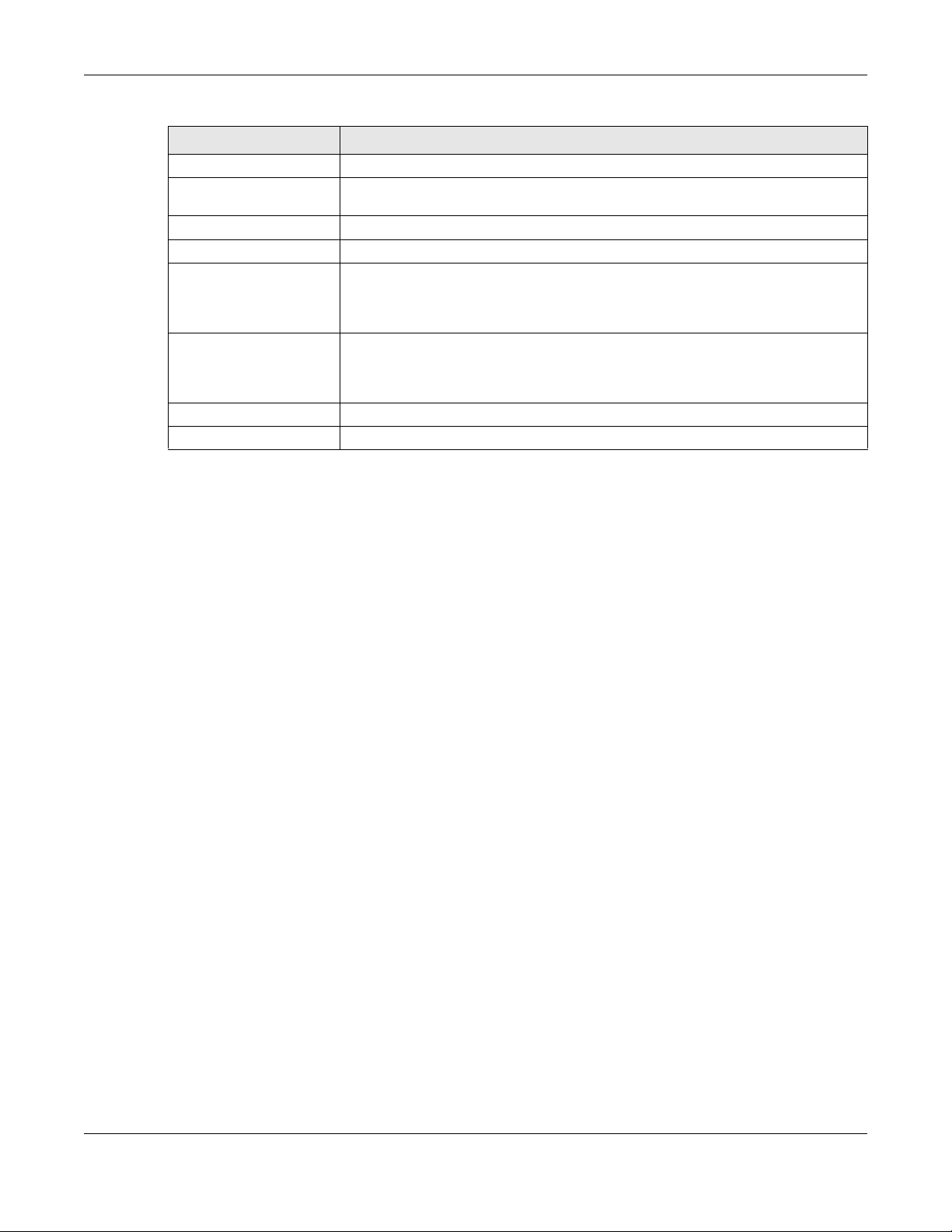
Table 1 NAP Series Comparison Table
FEATURES NAP102 NAP203 NAP303 NAP353
One Ethernet LAN Port No Yes Yes No
One PoE Enabled Uplink Port Yes Yes Yes Yes
External Antennas No No No Yes
One DC Power Socket Yes No Yes No
CHAPTER 1
Introduction
1.1.1 Management
The NAP is managed and provisioned automatically by the NCC (Nebula Control Center) when it is
connected to the Internet and has been registered to a site and organization. If you are having
problems with accessing the Internet and the NCC, you may need to change the NAP’s VLAN setting or
manually set its IP address through its built-in web-based configuration tool (web configurator).
You can use the Zyxel ZON utility, or check the connected gateway for the NAP's current LAN IP address.
Alternatively, disconnect the gateway or disable its DHCP server function, connect your computer to
the NAP’s LAN/Ethernet port and use the NAP's default static LAN IP address (192.168.1.2) to access the
web configurator. Make sure your computer’s IP address is in the same subnet as the NAP’s IP address.
NAP Series User’s Guide
7

Chapter 1 Introduction
1.1.2 Dual-Radio
The NAP is equipped with dual wireless radios. This means you can configure two different WiFi networks
to operate simultaneously.
Note: A different channel should be configured for each WLAN interface to reduce the
effects of radio interference.
You could use the 2.4 GHz band for regular Internet surfing and downloading while using the 5 GHz
band for time sensitive traffic like high-definition video, music, and gaming.
NAP Series User’s Guide
8

Figure 1 Dual-Radio Application
Chapter 1 Introduction
1.2 Ways to Manage the NAP
You can use the following ways to manage the NAP. If you need to change the NAP’s VLAN setting or
manually set its IP address before connecting it to the Internet, use its built-in Web Configurator.
Web Configurator
The Web Configurator allows basic NAP setup and monitoring using an Internet browser. This User’s
Guide provides information about the Web Configurator.
NCC (Nebula Control Center)
With the NCC, you can remotely manage and monitor the NAP through a cloud-based network
management system. See the NCC User’s Guide for more information.
ZON Utility
Zyxel One Network (ZON) Utility is a utility tool that assists you to set up and maintain network devices in a
more simple and efficient way. You can download the ZON Utility at www.zyxel.com and install it on
your computer (Windows operating system). For more information on ZON Utility see Section 1.3 on page
10.
Command-Line Interface (CLI)
The CLI allows you to use text-based commands to configure the NAP. You can access it using remote
management (for example, SSH or Telnet). See the Command Reference Guide for more information.
NAP Series User’s Guide
9

Chapter 1 Introduction
File Transfer Protocol (FTP)
This protocol can be used for firmware upgrades and configuration backup and restore.
1.3 Zyxel One Network (ZON) Utility
ZON Utility is a program designed to help you deploy and manage a network more efficiently. It detects
devices automatically and allows you to do basic settings on devices in the network without having to
be near it.
The ZON Utility issues requests via Zyxel Discovery Protocol (ZDP) and in response to the query, the device
responds back with basic information including IP address, firmware version, location, system and model
name in the same broadcast domain. The information is then displayed in the ZON Utility screen and you
can perform tasks like basic configuration of the devices and batch firmware upgrade in it. You can
download the ZON Utility at www.zyxel.com and install it on your computer (Windows operating system).
1.3.1 Requirements
Before installing the ZON Utility on your PC, please make sure it meets the requirements listed below.
Operating System
At the time of writing, the ZON Utility is compatible with:
• Windows 7 (both 32-bit / 64-bit versions)
• Windows 8 (both 32-bit / 64-bit versions)
• Windows 8.1 (both 32-bit / 64-bit versions)
• Window 10 (both 32-bit / 64-bit versions)
Note: To check for your Windows operating system version, right-click on My Computer >
Properties. You should see this information in the General tab.
Hardware
Here are the minimum hardware requirements to use the ZON Utility on your PC.
• Core i3 processor
•2GB RAM
• 100MB free hard disk
• WXGA (Wide XGA 1280x800)
1.3.2 Run the ZON Utility
1 Double-click the ZON Utility to run it.
2 The first time you run the ZON Utility, you will see if your device and firmware version support the ZON
Utility. Click the OK button to close this screen.
NAP Series User’s Guide
10

Chapter 1 Introduction
Figure 2 Supported Devices and Versions
If you want to check the supported models and firmware versions later, you can click the Show
information about ZON icon in the upper right hand corner of the screen. Then select the Supported
model and firmware version link. If your device is not listed here, see the device release notes for ZON
utility support. The release notes are in the firmware zip file on the Zyxel web site.
Figure 3 ZON Utility Screen
3 Select a network adapter to which your supported devices are connected.
NAP Series User’s Guide
11

Chapter 1 Introduction
1
2
3
4
56
7
8
9
10 11 12 13
Figure 4 Network Adapter
4 Click the Go button for the ZON Utility to discover all supported devices in your network.
Figure 5 Discovery
5 The ZON Utility screen shows the devices discovered.
Figure 6 ZON Utility Screen
6 Select a device and then use the icons to perform actions. Some functions may not be available for
your devices.
Note: You must know the selected device admin password before taking actions on the
device using the ZON utility icons.
NAP Series User’s Guide
12

Chapter 1 Introduction
Figure 7 Password Prompt
The following table describes the icons numbered from left to right in the ZON Utility screen.
Table 2 ZON Utility Icons
ICON DESCRIPTION
1 IP configuration Change the selected device’s IP address.
2 Renew IP Address Update a DHCP-assigned dynamic IP address.
3 Reboot Device Use this icon to restart the selected devices. This may be useful when troubleshooting
or upgrading new firmware.
4 Reset Configuration to
Default
5 Locator LED Use this icon to locate the selected device by causing its Locator LED to blink.
6 Web GUI Use this to access the selected device web configurator from your browser. You will
7 Firmware Upgrade Use this icon to upgrade new firmware to selected devices of the same model. Make
8 Change Password Use this icon to change the admin password of the selected device. You must know
9 Configure NCC
Discovery
10 ZAC Use this icon to run the Zyxel AP Configurator of the selected AP.
11 Clear and Rescan Use this icon to clear the list and discover all devices on the connected network
12 Save Configuration Use this icon to save configuration changes to permanent memory on a selected
13 Settings Use this icon to select a network adaptor for the computer on which the ZON utility is
Use this icon to reload the factory-default configuration file. This means that you will
lose all previous configurations.
need a username and password to log in.
sure you have downloaded the firmware from the Zyxel website to your computer and
unzipped it in advance.
the current admin password before changing to a new one.
You must have Internet access to use this feature. Use this icon to enable or disable
the Nebula Control Center (NCC) discovery feature on the selected device. If it’s
enabled, the selected device will try to connect to the NCC. Once the selected
device is connected to and has registered in the NCC, it’ll go into the Nebula cloud
management mode.
again.
device.
installed, and the utility language.
The following table describes the fields in the ZON Utility main screen.
Table 3 ZON Utility Fields
LABEL DESCRIPTION
Type This field displays an icon of the kind of device discovered.
Model This field displays the model name of the discovered device.
Firmware Version This field displays the firmware version of the discovered device.
NAP Series User’s Guide
13
Chapter 1 Introduction
Table 3 ZON Utility Fields
LABEL DESCRIPTION
MAC Address This field displays the MAC address of the discovered device.
IP Address This field displays the IP address of an internal interface on the discovered device that
first received an ZDP discovery request from the ZON utility.
System Name This field displays the system name of the discovered device.
Location This field displays where the discovered device is.
Status This field displays whether changes to the discovered device have been done
successfully. As the NAP does not support IP Configuration, Renew IP address and
Flash Locator LED, this field displays “Update failed”, “Not support Renew IP address”
and “Not support Flash Locator LED” respectively.
NCC Discovery This field displays if the discovered device supports the Nebula Control Center (NCC)
discovery feature. If it’s enabled, the selected device will try to connect to the NCC.
Once the selected device is connected to and has registered in the NCC, it’ll go into
the Nebula cloud management mode.
Serial Number Enter the admin password of the discovered device to display its serial number.
Hardware Version This field displays the hardware version of the discovered device.
1.4 Good Habits for Managing the NAP
Do the following things regularly to make the NAP more secure and to manage it more effectively.
• Change the system password through the NCC often. Use a password that’s not easy to guess and
that consists of different types of characters, such as numbers and letters.
• Write down the password and put it in a safe place.
1.5 Hardware Connections
See your Quick Start Guide and Section 1.1.1 on page 7 for information on making hardware
connections.
1.6 LEDs
The LEDs of your NAP303 or NAP203 can be controlled using the Suppression feature to turn LEDs on or off
after the device is ready. This can be done through the NCC.
Following are LED descriptions for the NAP series models.
1.6.1 NAP303
The LEDs will stay ON when the NAP303 is ready. You can change this setting with LED suppression.
NAP Series User’s Guide
14

Figure 8 NAP303 LEDs
Chapter 1 Introduction
The following table describes the LEDs.
Table 4 NAP303 LEDs
LED COLOR STATUS DESCRIPTION
PWR/SYS Amber Slowly blinks amber for
Green
Green On The NAP is ready for use.
Red On There is system error and the NAP cannot boot up, or the
one second and green
for one second
alternatively.
Slow Blinking (on for 1s,
off for 1s)
Fast Blinking (on for
50ms, off for 50ms)
Slow Blinking (blink for 3
times, off for 3s)
The NAP is booting up.
The WiFi module of the NAP is disabled or failed.
NAP suffered a system failure.
The NAP is undergoing firmware upgrade.
The Uplink port is disconnected.
NAP Series User’s Guide
15

Chapter 1 Introduction
Table 4 NAP303 LEDs (continued)
LED COLOR STATUS DESCRIPTION
Management Green On The NAP is managed by the NCC.
Slow Blinking (On for 1s,
Off for 1s)
Amber Slowly blinks amber for
Green
Amber Blinks amber and green
Green
WLAN Green On The 2.4 GHz WLAN is active.
WLAN Green On The 5 GHz WLAN is active.
one second and green
for one second
alternatively.
alternatively 3 times
and then turns solid
green for 3 seconds.
Off The 2.4 GHz WLAN is not active.
Off The 5 GHz WLAN is not active.
The NAP is connected to the NCC, but not registered.
The NAP is searching for (discovering) the NCC.
The NCC is connecting to the registered NAP.
UPLINK Amber/
LAN Amber/
Locator White Blinking The Locator is activated and will blink to show the actual
1.6.2 NAP203
The LEDs will stay ON when the NAP203 is ready. You can change this setting with LED suppression.
Green
Green
On Amber - The port is operating as a 100-Mbps connection.
Green - The port is operating as a Gigabit connection
(1000 Mbps).
Blinking The NAP is sending/receiving data through the port.
Off The port is not connected.
On Amber - The port is operating as a 100-Mbps connection.
Green - The port is operating as a Gigabit connection
(1000 Mbps).
Blinking The LAN port is sending/receiving data through the port.
Off The LAN port is not connected.
location of the NAP between several devices in the
network.
Off The Locator function is off.
NAP Series User’s Guide
16

Figure 9 NAP203 LEDs
Chapter 1 Introduction
The following table describes the LEDs.
Table 5 NAP203 LEDs
LED COLOR STATUS DESCRIPTION
PWR/SYS Red Slowly blinks red for one
Green
Green On The NAP is ready for use.
Red On There is system error and the NAP cannot boot up, or the
second and green for
one second
alternatively.
Fast Blinking (on for
50ms, Off for 50ms)
Slow Blinking (blink for 3
times, Off for 3s)
Slow Blinking (blink for 2
times, Off for 3s)
The NAP is booting up.
NAP suffered a system failure.
The NAP is undergoing firmware upgrade.
The Uplink port is disconnected.
The WiFi module of the NAP is disabled or failed.
NAP Series User’s Guide
17

Chapter 1 Introduction
Table 5 NAP203 LEDs (continued)
LED COLOR STATUS DESCRIPTION
Management Green On The NAP is managed by the NCC.
Slow Blinking (On for 1s,
Off for 1s)
Amber Slowly blinks amber for
Green
Amber Blinks amber and green
Green
WLAN Green On The antenna switch is set to “Ceiling” for the radio.
Amber On The antenna switch is set to “Wall” for the radio.
WLAN Green On The antenna switch is set to “Ceiling” for the radio.
Amber On The antenna switch is set to “Wall” for the radio.
one second and green
for one second
alternatively.
alternatively 3 times
and then turns solid
green for 3 seconds.
Off The 2.4 GHz WLAN is not active.
The NAP is connected to the NCC, but not registered.
The NAP is searching for (discovering) the NCC.
The NCC is connecting to the registered NAP.
The 2.4 GHz WLAN is active.
The 2.4 GHz WLAN is active.
The 5 GHz WLAN is active.
UPLINK Amber/
LAN Amber/
Locator White Blinking The Locator is activated and will blink to show the actual
1.6.3 NAP102
The following are the LED descriptions for your NAP102.
Green
Green
The 5 GHz WLAN is active.
Off The 5 GHz WLAN is not active.
On Amber - The port is operating as a 100-Mbps connection.
Green - The port is operating as a Gigabit connection
(1000 Mbps).
Blinking The NAP is sending/receiving data through the port.
Off The port is not connected.
On Amber - The port is operating as a 100-Mbps connection.
Green - The port is operating as a Gigabit connection
(1000 Mbps).
Blinking The LAN port is sending/receiving data through the port.
Off The LAN port is not connected.
location of the NAP between several devices in the
network.
Off The Locator function is off.
NAP Series User’s Guide
18
 Loading...