


 Loading...
ZXSDR R8860
CDMA Remote Radio Unit-8860
Installation Manual
ZTE CORPORATION
NO. 55, Hi-tech Road South, ShenZhen, P.R.China
Postcode: 518057
Tel: +86-755-26771900
Fax: +86-755-26770801
URL: http://ensupport.zte.com.cn
E-mail: support@zte.com.cn

LEGAL INFORMATION
Copyright © 2011 ZTE CORPORATION.
The contents of this document are protected by copyright laws and international treaties. Any reproduction or distribution of this document or any portion of this document, in any form by any means, without the prior written consent of ZTE CORPORATION is prohibited. Additionally, the contents of this document are protected by contractual confidentiality obligations.
All company, brand and product names are trade or service marks, or registered trade or service marks, of ZTE CORPORATION or of their respective owners.
This document is provided “as is”, and all express, implied, or statutory warranties, representations or conditions are disclaimed, including without limitation any implied warranty of merchantability, fitness for a particular purpose, title or non-infringement. ZTE CORPORATION and its licensors shall not be liable for damages resulting from the use of or reliance on the information contained herein.
ZTE CORPORATION or its licensors may have current or pending intellectual property rights or applications covering the subject matter of this document. Except as expressly provided in any written license between ZTE CORPORATION and its licensee, the user of this document shall not acquire any license to the subject matter herein.
ZTE CORPORATION reserves the right to upgrade or make technical change to this product without further notice. Users may visit ZTE technical support website http://ensupport.zte.com.cn to inquire related information.
The ultimate right to interpret this product resides in ZTE CORPORATION.
Revision History
Revision No. |
Revision Date |
Revision Reason |
|
|
|
R1.0 |
08/30/2010 |
First Edition |
|
|
|
R1.1 |
12/30/2010 |
Modify Style sheetDrop the content of installing Wave TrapDrop |
|
|
the content of installing Sun shield |
|
|
|
R1.2 |
01/20/2011 |
Waterproof processing must be performed on all the outdoor |
|
|
metal connectors of the RRUs. |
|
|
|
R1.3 |
02/20/2011 |
Add installing PIMDC Drop the Floor Stand-mounted Installation |
|
|
ModeDrop the Simplified Cabinet Integrated Installation Mode |
|
|
|
Serial Number: SJ-20100722143906-002
Publishing Date: 02/20/2011(R1.3)

Declaration of RoHS
Compliance
To minimize the environmental impact and take more responsibility to the earth we live, this document shall serve as formal declaration that ZXSDR R8860 manufactured by ZTE CORPORATION are in compliance with the Directive 2002/95/EC of the European Parliament - RoHS (Restriction of Hazardous Substances) with respect to the following substances:
•Lead (Pb)
•Mercury (Hg)
•Cadmium (Cd)
•Hexavalent Chromium (Cr (VI))
•PolyBrominated Biphenyls (PBB’s)
•PolyBrominated Diphenyl Ethers (PBDE’s)
…
The ZXSDR R8860 manufactured by ZTE CORPORATION meet the requirements of EU 2002/95/EC; however, some assemblies are customized to client specifications. Addition of specialized, customer-specified materials or processes which do not meet the requirements of EU 2002/95/EC may negate RoHS compliance of the assembly. To guarantee compliance of the assembly, the need for compliant product must be communicated to ZTE CORPORATION in written form. This declaration is issued based on our current level of knowledge. Since conditions of use are outside our control, ZTE CORPORATION makes no warranties, express or implied, and assumes no liability in connection with the use of this information.
I
II

FCC & IC STATEMENT
This device complies with part 15 of the FCC Rules. Operation is subject to the following two conditions:
1.This device may not cause harmful interference.
2.This device must accept any interference received, including interference that may cause undesired operation.
This Class[A] digital apparatus complies with Canadian ICES-003.
 Note:
Note:
Working with the equipment while in operation, may expose the technician to RF electromagnetic fields that exceed FCC rules for human exposure. Visit the FCC website at www.fcc.gov/oet/rfsafety to learn more about the effects of exposure to RF electromagnetic fields.
Changes or modifications to this unit not expressly approved by the party responsible for compliance will void the user’s authority to operate the equipment. Any change to the equipment will void FCC and IC grant.
This equipment has been tested and found to comply with the limits for a Class A digital device, pursuant to the FCC and IC Rules. This equipment generates, uses and can radiate radio frequency energy and, if not installed and used in accordance with the instructions, may cause harmful interference to radio communications. However, there is no guarantee that interference will not occur in a particular installation.
I
II

RF Exposure Information for PMR
The product generates RF electromagnetic energy during transmit mode.
This radio is designed for and classified as “Occupational Use Only”, meaning it must be used only during the course of employment by individuals aware of the hazards, and the ways to minimize such hazards. This radio is NOT intended for use by the “General Population” in an uncontrolled environment.
This radio has been tested and complies with the FCC RF exposure limits for “Occupational Use Only”.
In addition, the product complies with the following Standards and Guidelines with regard to RF energy and electromagnetic energy levels and evaluation of such levels for exposure to humans:
1.FCC OET Bulletin 65 Edition 97-01 Supplement C, Evaluating Compliance with FCC Guidelines for Human Exposure to Radio Frequency Electromagnetic Fields.
2.tAmerican National Standards Institute (C95.1-1992), IEEE Standard for Safety Levels with Respect to Human Exposure to Radio Frequency Electromagnetic Fields, 3 kHz to 300 GHz.
3.American National Standards Institute (C95.3-1992), IEEE Recommended Practice for the Measurement of Potentially Hazardous Electromagnetic Fields– RF and Microwave.
4.The following accessories are authorized for use with this product. Use of accessories other than those (listed in the instruction) specified may result in RF exposure levels exceeding the FCC requirements for wireless RF exposure.
I
II

About This Manual
Purpose
ZXSDR R8860 is an outdoor remote RF unit. Composing an integrated BTS, ZXSDR R8860 and ZXSDR R8860 implement wireless transmission within coverage areas, control of wireless channel as well as communication with BSC.
This manual provides basic installation guide for engineering personnel who perform ZXSDR R8860 hardware installation. At the same time, it serves for the reference material for the personnel responsible for operation and maintenance.
Intended Audience
This document is intended for engineers and technicians who perform operation activities ZXSDR R8860.
•Engineering technicians
•Equipment installation engineers
•Equipment commissioning engineers
Prerequisite Skill and Knowledge
To use this document effectively, users should have a general understanding of ZXSDR R8860 equipment and its components. Familiarity with the following is helpful:
•ZXSDR R8860 hardware structure
•Basic software knowledge
What is in This Manual
This manual contains the following chapters:
Chapter |
Summary |
Chapter 1 Safety Description |
Describes safety precautions during ZXSDR R8860 installation |
|
or operation maintenance as well as meanings of various safety |
|
symbols. |
|
|
Chapter 2 Installation |
Describes the ZXSDR R8860 installation flows and installation |
Overview |
precautions. |
|
|
Chapter 3 Cabinet Installation |
Describes four installation modes of ZXSDR R8860 cabinet and |
|
installation situations. |
|
|
Chapter 4 External Cable |
Describes the installation methods of various ZXSDR R8860 external |
Installation |
cables. |
|
|
Chapter 5 Main Antenna |
Describes the installation flows and installation methods of ZXSDR |
Feeder System Installation |
R8860 main antenna feeder system. |
|
|
I

Chapter |
Summary |
|
|
Chapter 6 Hardware |
Describes the inspection methods of cabinet and cables after |
Installation Inspection |
installation completion. |
|
|
Chapter 7 Power on and off |
Describes the methods and precautions of ZXSDR R8860 power |
|
on and off . |
|
|
Conventions
ZTE documents employ the following typographical conventions.
Typeface |
Meaning |
|
|
Italics |
References to other Manuals and documents. |
|
|
“Quotes” |
Links on screens. |
|
|
Bold |
Menus, menu options, function names, input fields, radio button names, check |
|
boxes, drop-down lists, dialog box names, window names. |
|
|
CAPS |
Keys on the keyboard and buttons on screens and company name. |
|
|
|
Note: Provides additional information about a certain topic. |
|
|
|
Checkpoint: Indicates that a particular step needs to be checked before |
|
proceeding further. |
|
|
|
Tip: Indicates a suggestion or hint to make things easier or more productive |
|
for the reader. |
|
|
Mouse operation conventions are listed as follows:
Typeface |
Meaning |
Click |
Refers to clicking the primary mouse button (usually the left mouse button) once. |
|
|
Double-click |
Refers to quickly clicking the primary mouse button (usually the left mouse button) |
|
twice. |
|
|
Right-click |
Refers to clicking the secondary mouse button (usually the right mouse button) |
|
once. |
|
|
II
Contents
Declaration of RoHS Compliance ................................................................. |
I |
|
FCC & IC STATEMENT ................................................................................... |
I |
|
RF Exposure Information for PMR................................................................ |
I |
|
About This Manual ......................................................................................... |
I |
|
Chapter 1 Safety Description .................................................................... |
1-1 |
|
1.1 |
Safety Specifications Guide ................................................................................ |
1-1 |
1.2 |
Safety Symbols.................................................................................................. |
1-2 |
1.3 |
Safety Instructions.............................................................................................. |
1-3 |
Chapter 2 Installation Overview................................................................ |
2-1 |
|
2.1 |
Components to be Installed................................................................................. |
2-1 |
2.2 |
Installation Flow ................................................................................................. |
2-1 |
2.3 |
Installation Preparation ....................................................................................... |
2-2 |
|
2.3.1 Engineering Condition Inspection .............................................................. |
2-2 |
|
2.3.2 Tools and Instruments Preparation ............................................................ |
2-4 |
|
2.3.3 On-site Documents .................................................................................. |
2-9 |
|
2.3.4 Unpacking Acceptance........................................................................... |
2-10 |
Chapter 3 Cabinet Installation................................................................... |
3-1 |
|
3.1 |
Engineering Indices............................................................................................ |
3-1 |
3.2 |
Pole-mounted Installation Mode .......................................................................... |
3-2 |
|
3.2.1 Components Used in Pole-mount Installation ............................................. |
3-2 |
|
3.2.2 Installing Single Cabinet on Pole (Pole–Mount ) ......................................... |
3-5 |
|
3.2.3 Installing Two ZXSDR R8860 Pole-mount Cabinets.................................... |
3-6 |
|
3.2.4 Installing Three ZXSDR R8860 Cabinets on Pole ....................................... |
3-9 |
3.3 |
Wall-mounted Installation Mode.......................................................................... |
3-11 |
|
3.3.1 Components Used in Wall-Mount Installation ............................................ |
3-11 |
|
3.3.2 Installing Cabinet on Wall (Wall-Mount).................................................... |
3-12 |
Chapter 4 External Cable Installation....................................................... |
4-1 |
|
4.1 |
External Cable Layout ........................................................................................ |
4-1 |
4.2 |
External Cable Installation Flow .......................................................................... |
4-2 |
4.3 |
Specifications of 1+3+3 Waterproof Processing with Plaster and Tape................... |
4-4 |
4.4 |
Installing Power Cable........................................................................................ |
4-6 |
4.5 |
Installing Grounding Cable.................................................................................. |
4-7 |
I
4.6 |
Installing Fiber between BBU and RRU................................................................ |
4-9 |
4.7 |
Installing Fiber between RRU and RRU ............................................................. |
4-10 |
4.8 |
Installing Environment Monitoring Cable ............................................................ |
4-12 |
4.9 |
Installing AISG Control Cable............................................................................ |
4-13 |
4.10 Installing Frequency Point Extension Cable...................................................... |
4-14 |
|
4.11 Installing Jumper ............................................................................................ |
4-15 |
|
4.12 Installing PIMDC ............................................................................................ |
4-16 |
|
|
4.12.1 PIMDC echnical Indices........................................................................ |
4-16 |
|
4.12.2 PIMDC Appearance.............................................................................. |
4-17 |
|
4.12.3 PIMDC Installation Description .............................................................. |
4-18 |
Chapter 5 Main Antenna Feeder System Installation.............................. |
5-1 |
|
5.1 |
Main Antenna Feeder System Structure............................................................... |
5-1 |
5.2 |
Main Antenna Feeder System Installation Preparation.......................................... |
5-7 |
5.3 |
Main Antenna Feeder System Installation Flow .................................................... |
5-8 |
5.4 |
Antenna Installation............................................................................................ |
5-9 |
|
5.4.1 Antenna Installation Technical Specifications.............................................. |
5-9 |
|
5.4.2 Antenna Installation Position ................................................................... |
5-10 |
|
5.4.3 Installing Directional Antenna ................................................................. |
5-10 |
|
5.4.4 Installing Omni Antenna ......................................................................... |
5-13 |
|
5.4.5 Connecting Jumper and Antenna ............................................................ |
5-14 |
5.5 |
Feeder Installation............................................................................................ |
5-15 |
|
5.5.1 Feeder Cutting Principle ......................................................................... |
5-15 |
|
5.5.2 Installing Feeder on Top of Building ......................................................... |
5-16 |
|
5.5.3 Installing Feeder on Tower...................................................................... |
5-18 |
|
5.5.4 Feeder Layout Principles ........................................................................ |
5-19 |
|
5.5.5 Fixing Main Feeder................................................................................. |
5-20 |
|
5.5.6 Feeder Grounding Principle .................................................................... |
5-20 |
|
5.5.7 Installing Feeder Grounding Clips............................................................ |
5-22 |
|
5.5.8 Connecting Jumper and Feeder .............................................................. |
5-25 |
5.6 |
Installing Feeder Hermetic-window.................................................................... |
5-25 |
5.7 |
Feeder Indoor Ingoing ...................................................................................... |
5-27 |
|
5.7.1 Feeder Indoor Arrangement Principle ...................................................... |
5-27 |
|
5.7.2 Leading Main Feeder into Room ............................................................. |
5-28 |
|
5.7.3 Installing Top-equipment Jumper............................................................. |
5-30 |
5.8 |
Performing Antenna Feeder System Test........................................................... |
5-31 |
5.9 |
Performing Outdoor-Connector Waterproof Processing....................................... |
5-32 |
5.10 Performing Feeder Hermetic-window Waterproof Processing ............................ |
5-36 |
|
II
5.11 Chassis Jumper Installation Description ........................................................... |
5-39 |
5.12 VSWR Test .................................................................................................... |
5-40 |
Chapter 6 Hardware Installation Inspection............................................. |
6-1 |
|
6.1 |
Checking Cabinet Installation.............................................................................. |
6-1 |
6.2 |
Checking Cable Installation................................................................................. |
6-1 |
|
6.2.1 Cables Installation General Specification ................................................... |
6-1 |
|
6.2.2 Power and Grounding Cables Installation Check ........................................ |
6-3 |
|
6.2.3 Optical Fiber Installation Check................................................................. |
6-4 |
6.3 |
Checking Main Antenna System Installation......................................................... |
6-4 |
Chapter 7 Power on and off....................................................................... |
7-1 |
|
7.1 |
Power on Preparation......................................................................................... |
7-1 |
7.2 |
Power ON.......................................................................................................... |
7-1 |
7.3 |
Power OFF ........................................................................................................ |
7-2 |
Appendix A Cabinet-combined Installation ............................................ |
A-1 |
|
A.1 |
Components Used in Cabinet-combining Installation ............................................ |
A-1 |
A.2 |
Performing Cabinet-combination......................................................................... |
A-2 |
Appendix B Cascading Cabinet Installation ........................................... |
B-1 |
|
B.1 |
Components Used in Cascading Installation ........................................................ |
B-1 |
B.2 |
Performing Cabinet Cascading ........................................................................... |
B-2 |
Appendix C OAU........................................................................................ |
C-1 |
|
C.1 OAU Appearance and Interface .......................................................................... |
C-1 |
|
C.2 Installing OAU in Pole-mount Mode..................................................................... |
C-2 |
|
C.3 Installation OAU in Wall-mount Mode .................................................................. |
C-9 |
|
C.4 Installing OAU Cable........................................................................................ |
C-12 |
|
Appendix D OLP48-2................................................................................. |
D-1 |
|
D.1 OLP48-2 Technical Indices................................................................................. |
D-1 |
|
D.2 OLP48-2 Appearance and Interface.................................................................... |
D-1 |
|
D.3 OLP48-2 Installation Description......................................................................... |
D-3 |
|
Appendix E ILP48-3.................................................................................... |
E-1 |
|
E.1 |
ILP48-3 Technical Indices................................................................................... |
E-1 |
E.2 |
ILP48-3 Appearance and Interface...................................................................... |
E-2 |
E.3 |
ILP48-3 Installation Description........................................................................... |
E-3 |
Appendix F AC Lightning Arrester ........................................................... |
F-1 |
|
F.1 AC Lightning Technical Indices............................................................................ |
F-1 |
|
F.2 AC Lightning Appearance and Interface............................................................... |
F-2 |
|
F.3 AC Lightning Installation Description.................................................................... |
F-3 |
|
III
F.4 Installing Shielded Grounding Kit ........................................................................ |
F-7 |
Appendix G PDM ....................................................................................... |
G-1 |
|
G.1 |
PDM Appearance and Interface......................................................................... |
G-1 |
G.2 |
Installing PDM.................................................................................................. |
G-1 |
Figures............................................................................................................. |
I |
|
Tables ............................................................................................................. |
V |
|
Glossary ....................................................................................................... |
VII |
|
IV

Chapter 1
Safety Description
Table of Contents
Safety Specifications Guide........................................................................................ |
1-1 |
Safety Symbols .......................................................................................................... |
1-2 |
Safety Instructions...................................................................................................... |
1-3 |
1.1 Safety Specifications Guide
These safety instructions must be considered as supplementary for local safety regulations. The priority must be given to local safety regulations if there is any conflict between the two.
The maintenance personnel must have the knowledge of safety operations and maintenance with required qualification and technical background.
 Warning!
This device complies with part 15 of the FCC Rules. Operation is subject to the following two conditions:
•This device may not cause harmful interference.
•This device must accept any interference received, including interference that may cause undesired operation.
Changes or modifications not expressly approved by the party responsible for compliance could void the user's authority to operate the equipment.
The equipment is intended for installation in RESTRICTED ACCESS LOCATIONS.
All the operation and maintenance personnel must follow the safety precautions and instructions provided by ZTE Corporation to avoid any accident.
 Note:
Note:
ZTE Corporation does not bear any liabilities incurred because of violation of the universal safety operation requirements, or violation of safety standards for designing, manufacturing and using the equipment.
1-1
SJ-20100722143906-002|02/20/2011(R1.3) |
ZTE Proprietary and Confidential |
ManualInstallationR8860ZXSDR
Statement:ExposureRadiationFCC
uncontrolledanforforthsetlimitsexposureradiationFCCwithcompliesequipmentThis 4mdistanceminimumwithoperatedandinstalledbeshouldequipment.Thisenvironment body.yourradiator&thebetween
SymbolsSafety1.2 |
|
|
|
betoprecautionssafetytheofusertheprompttoareTheysymbols.safetylists1-1Table |
|
|
maintenance.andoperationR8860ZXSDRduringobserved |
|
|
DescriptionSymbolsSafety1-1Table |
|
|
|
|
|
SymbolsSafety |
Meaning |
|
|
|
|
|
forbiddenisSmokingsmoking:No |
|
|
|
|
|
stored.becanflammablesNoflammables:No |
|
|
|
|
|
touch.notDotouching:No |
|
|
|
|
|
attentions.safetyGeneralsymbol:alertingUniversal |
|
|
|
|
|
shock.electricofRiskshock:Electric |
|
|
|
|
|
electricity.statictosensitivebemaydeviceTheElectrostatic: |
|
|
|
|
|
field.electromagneticstrongofBewareMicrowave: |
|
|
|
|
|
beam.laserstrongofBewareLaser: |
|
|
|
|
|
scald.ofBewareScald: |
|
|
|
levels:threeintoclassifiedaresymbolsalarmuniversalthesymbols,safetytheseAmongst describedarelevelsthreetheofmeaningsandformatsThecaution.andwarning,danger, below:as
|
2-1 |
|
|
|
|
002|02/20/2011(R1.3)-20100722143906-SJ |
|
ConfidentialandProprietaryZTE |

Chapter 1 Safety Description
 Danger!
Indicates a potentially hazardous situation which, if not avoided, will result in death or serious injury of people, or equipment damages and breakdown.
 Warning!
Indicates a potentially hazardous situation which, if not avoided, could result in death or serious injury.
 Caution!
Indicates a potentially hazardous situation which, if not avoided, could result in serious injuries, equipment damages or interruption of part services.
1.3 Safety Instructions
This section describes the safety instructions related to electrical safety, antistatic, heavy objects and modules.
Electrical Safety Instructions
The following are the electrical safety instructions about tools, high voltage, power cables, holes and lightning:
•Tools
Use special tools rather than common tools for high-voltage and AC operations.
•High Voltage
 Danger!
High voltage is hazardous. Direct or indirect contact with high voltage or main supply using a wet object could result in death.
àStrictly follow local safety rules to install AC power devices.
àInstallation staff must be qualified for performing high-voltage and AC operations.
1-3
SJ-20100722143906-002|02/20/2011(R1.3) |
ZTE Proprietary and Confidential |

ZXSDR R8860 Installation Manual
àDo not wear any watch, hand chain, bracelet, ring or any other conductive objects during such operations.
àPrevent moisture from accumulating on the equipment during operations in a damp environment.
•Power Cable
 Warning!
Never install or uninstall power cables while they are live. Otherwise, the power cable, when contacting a conductor, may result in sparks or electric arc causing a fire or even damage to eyes.
àMake sure of shutting off power supply before installing or disconnecting a power cable.
àBefore connecting the power cable, make sure that the connecting cable and its label are appropriate for the actual installation requirements.
•Drilling Holes
 Warning!
It is not allowed to drill chassis holes without permission.
àUnqualified drilling could damage wiring and cables inside the chassis. Additionally, metal pieces inside the chassis created by the drilling could result in a short circuit. Use insulation protection gloves and first move cables inside a chassis away when drilling is necessary on a chassis.
àProtect eyes during drilling as dust or flying debris may damage eyes.
àClean any debris in time after drilling.
•Lightning
 Danger!
Do not perform high-voltage, AC, iron tower or mast operations in a thunderstorm.
Thunderstorms would give rise to a strong electromagnetic field in the atmosphere. Therefore, the equipment must be grounded and protected in time against lightning strikes.
1-4
SJ-20100722143906-002|02/20/2011(R1.3) |
ZTE Proprietary and Confidential |

Chapter 1 Safety Description
Antistatic Safety Instructions
 Caution!
Static electricity produced by human body can damage static-sensitive components on circuit board, such as large-scale integrated circuits.
•Friction caused by human body activities is the root cause of electrostatic charge accumulation. Static voltage carried by a human body in a dry environment can be up to 30 kV, and can remain there for a long time. An operator with static electricity may discharge electricity through a component when he/she touches the conductor and causing damage.
•Wear an antistatic wrist strap (the other end of wrist strap must be well grounded) before touching the equipment or holding a plug-in board, circuit board, Integrated Circuit (IC) chip or other devices, to prevent human static electricity from damaging sensitive components.
•The antistatic wrist strap used must be subject to regular check. Do not replace the cable of an antistatic wrist strap with any other cables.
•Do not contact static-sensitive modules with any object that easily generates static electricity. For example, friction of package bag, transfer box and transfer belt made from insulation plastic may cause static electricity on components. Discharge of static electricity may damage components when they contact a human body or the ground.
•Modules should only contact materials such as an antistatic bag. Keep modules in antistatic bags during storage and transportation.
•Discharge static electricity of the test device before use, that is, ground the test device first.
•Do not place the module near a strong DC magnetic field, such as the cathode-ray tube of a monitor. Keep the module at least 10 cm away.
Hoisting Heavy Objects
 Warning!
When hoisting heavy objects, ensure that nobody is standing or walking under the hoisted object.
•Ensure the hoister can meet hoisting requirements when disassembling heavy equipment, or moving and replacing equipment.
•The installation personnel must be duly trained and qualified for hoisting operations.
•Hoisting tools must be inspected and complete before service.
1-5
SJ-20100722143906-002|02/20/2011(R1.3) |
ZTE Proprietary and Confidential |

ZXSDR R8860 Installation Manual
•Make sure that hoisting tools are fixed firmly on a sufficiently secured object or wall before the hoisting operation.
•Give brief oral instructions during hoisting operations to prevent any mishap.
Unplugging/Plugging a Module
•Never plug a module with excessive force, to ensure that the pins on the backplane do not get deformed.
•Plug the module right into the slot and make sure module circuit faces do not contact each other lest any short circuit may occur.
•Keep hands off the module circuit, components, connectors and cable trough when holding a module.
Rack Mount Safety Instructions
Rack Mount Instructions - The following or similar rack-mount instructions are included with the installation instructions:
•Elevated Operating Ambient - If installed in a closed or multi-unit rack assembly, the operating ambient temperature of the rack environment may be greater than room ambient. Therefore, consideration should be given to installing the equipment in an environment compatible with the maximum ambient temperature (Tma) specified by the manufacturer.
•Reduced Air Flow - Installation of the equipment in a rack should be such that the amount of air flow required for safe operation of the equipment is not compromised.
•Mechanical Loading - Mounting of the equipment in the rack should be such that a hazardous condition is not achieved due to uneven mechanical loading.
•Circuit Overloading - Consideration should be given to the connection of the equipment to the supply circuit and the effect that overloading of the circuits might have on overcurrent protection and supply wiring. Appropriate consideration of equipment nameplate ratings should be used when addressing this concern.
•Reliable Earthing - Reliable earthing of rack-mounted equipment should be maintained. Particular attention should be given to supply connections other than direct connections to the branch circuit (e.g. use of power strips).
Other Safety Instructions
 Note:
Note:
Do not perform maintenance or debugging independently, unless a qualified person is present.
•Perform an airtight test before RRU delivery, and prohibit disassembling the RRU on site.
1-6
SJ-20100722143906-002|02/20/2011(R1.3) |
ZTE Proprietary and Confidential |
Chapter 1 Safety Description
•Replacing any parts or making any changes to the equipment might result in an unexpected danger. Therefore, be sure not to replace any parts or perform any changes to the equipment unless authorized otherwise.
•Due to that RRU is in high temperature during running, the RRU should be installed in some regions out of operators' reach or strictly restricted.
•Contact ZTE office if you have any question, to ensure your safety.
1-7
SJ-20100722143906-002|02/20/2011(R1.3) |
ZTE Proprietary and Confidential |

ZXSDR R8860 Installation Manual
This page intentionally left blank.
1-8
SJ-20100722143906-002|02/20/2011(R1.3) |
ZTE Proprietary and Confidential |

Chapter 2
Installation Overview
Table of Contents
Components to be Installed........................................................................................ |
2-1 |
Installation Flow ......................................................................................................... |
2-1 |
Installation Preparation............................................................................................... |
2-2 |
2.1 Components to be Installed
For ZXSDR R8860, the following components will be installed:
•ZXSDR R8860 cabinet and components
 Note:
Note:
The inner cables and functional modules/boards in the cabinet are already installed before equipment delivery.
•Sunshield (used for the outdoor ZXSDR R8860 installation)
•Cables
•Antenna feeder system including antenna, jumpers and feeder
2.2Installation Flow
The installation flow of ZXSDR R8860 is demonstrated in Figure 2-1 . However, it is not required to strictly follow the steps showed in this flow. The actual installation procedures depend on the requirements on site.
2-1
SJ-20100722143906-002|02/20/2011(R1.3) |
ZTE Proprietary and Confidential |

ZXSDR R8860 Installation Manual
Figure 2-1 Installation Flow
2.3 Installation Preparation
2.3.1 Engineering Condition Inspection
Before installing devices, follow the requirements of Environment Acceptance Report and check installation environment. The following content is just as a reference.
Installation Position Inspection
ZXSDR R8860 installation position should accord with the requirements of engineering design, the specified requirements as follows:
•Avoid dusty, harmful-gas or explosive-goods environment;
2-2
SJ-20100722143906-002|02/20/2011(R1.3) |
ZTE Proprietary and Confidential |

Chapter 2 Installation Overview
•Avoid the places with big shock or strong noise;
•Far away substation;
•Far away pollution source;
•Avoid an industrial boiler and heating boiler;
•Far away high-power wireless interference source.
Temperature and Humidity Inspection
ZXSDR R8860 temperature and humidity in work environment should meet the requirements, as shown in
Power Supply Inspection
The requirements of ZXSDR R8860 power supply are described as follows.
1.DC power supply: ZXSDR R8860 is –48 V DC power supply and the voltage of power supply is –40 V DC~–57 V DC.
2.Indirect AC power supply: adopt an outdoor AC unit (OAU); the OAU can provide 220V AC power supply for one ZXSDR B8200 C100 and one ZXSDR R8860 at the same time.
Lightning Inspection
The ZXSDR R8860 lightning requirements are described as follows.
•Outdoor Installation
1.For DC power supply, configure an outdoor DC lightning box OLP48-2. If the DC power is exported from the equipment room, the length of power cable is more than 10 m (less than 50 m) and the output end of indoor DC power is not configured with B-level or above lightning devices, it is required to configure an indoor DC lightning box ILP48–3 in the equipment room.
2.For indirect AC power supply, it is required to configure an AC lightning box (ZXPCS combined arrester).
•For indoor installation, if the power cable is distributed outdoors, configure the power lightning box according to the conditions of outdoor installation.
Grounding Inspection
ZXSDR R8860 adopts an associated grounding mode. The value of grounding resistance is not more than 5 ohm.
Other Inspections
1.The corollary devices or components should accord with the requirements of ZXSDR R8860 engineering design drawing.
2.The transmission devices interconnected with BBU should have been prepared.
2-3
SJ-20100722143906-002|02/20/2011(R1.3) |
ZTE Proprietary and Confidential |
ZXSDR R8860 Installation Manual
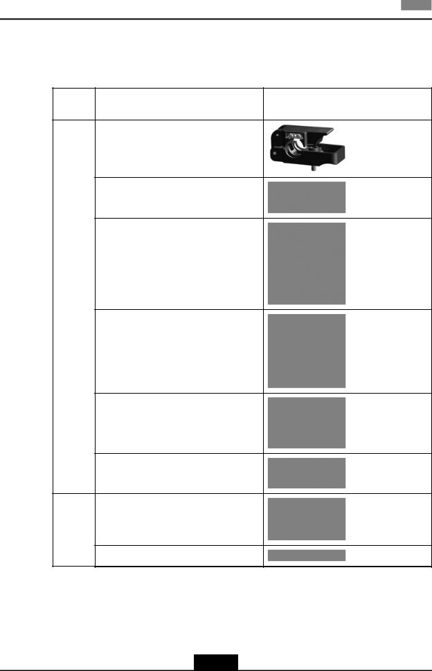
2.3.2 Tools and Instruments Preparation
Table 2-1 shows tools and meters list required during installation.
Table 2-1 Tool and Meter List
Cate-
Name |
Example |
gory
One feeder connector knife
One 75 Ω coaxial cable stripper
One multi-functional crimping pliers
Special- |
|
purpose |
|
tools |
One multimeter |
One standing wave ratio tester
One earth resistance tester
One electric percussion drill
Punching tools
Several auxiliary percussion drill bits
2-4
SJ-20100722143906-002|02/20/2011(R1.3) |
ZTE Proprietary and Confidential |

|
|
|
Chapter 2 Installation Overview |
|
|
|
|
|
|
|
|
|
Cate- |
Name |
Example |
|
gory |
||
|
|
|
|
|
|
|
|
|
|
One vacuum cleaner |
|
|
|
|
|
|
|
Power connector board (providing at least 3 |
|
|
|
two-phase sockets and 3 three-phase sock- |
|
|
|
ets, with the current capacity larger than 15 |
|
|
|
A) |
|
|
|
|
|
|
|
Cross screwdrivers (4”, 6” and 8” each) |
|
|
|
|
|
|
|
Flathead screwdrivers (4”, 6” and 8” each) |
|
|
|
|
|
|
|
Adjustable wrenches (6”, 8”, 10” and 12” |
|
|
|
each) |
|
|
|
|
|
|
|
Dual-purpose wrenches (17” and 19” each) |
|
|
|
|
|
|
|
One set of socket wrenches |
|
|
General- |
|
|
|
purpose |
|
|
|
tools |
|
|
|
|
|
|
|
|
One paper knife |
|
|
|
|
|
|
|
5 kg nail hammer |
|
|
|
|
|
|
|
One 300 W iron and one 40 W iron |
|
|
|
|
|
2-5
SJ-20100722143906-002|02/20/2011(R1.3) |
ZTE Proprietary and Confidential |

ZXSDR R8860 Installation Manual
|
Cate- |
Name |
Example |
||
|
gory |
||||
|
|
|
|
|
|
|
|
|
|
|
|
|
|
One set of inner-hexagon wrench |
|
||
|
|
|
|
|
|
|
|
Solder wires |
|
||
|
|
|
|
|
|
|
|
One 50 m (164 feet) tape measure |
|
||
|
|
|
|
|
|
|
|
One 5 m (16 feet) steel tape |
|
||
|
Mea- |
|
|
|
|
|
sure- |
|
|
|
|
|
ment |
|
|
|
|
|
tools |
One angle instrument |
|
||
|
|
|
|
|
|
|
|
One compass |
|
||
|
|
|
|
|
|
|
|
|
|
|
|
|
|
|
2-6 |
|
|
|
|
|
|
||
SJ-20100722143906-002|02/20/2011(R1.3) |
ZTE Proprietary and Confidential |
||||

|
|
|
Chapter 2 Installation Overview |
|
|
|
|
|
|
|
|
|
Cate- |
Name |
Example |
|
gory |
||
|
|
|
|
|
|
|
|
|
|
One level bar |
|
|
|
|
|
|
|
One plumb |
|
|
|
|
|
|
|
Antistatic wrist strap |
|
|
|
|
|
|
|
slip-proof gloves |
|
|
Protec- |
|
|
|
tion tools |
|
|
|
|
|
|
|
|
Safety helmet |
|
|
|
|
|
|
|
One hacksaw (with several saw blades) |
|
|
|
|
|
|
|
One pair of sharp-nose pliers (8″) |
|
|
|
|
|
|
|
One pair of diagonal pliers (8″) |
|
|
Clamp |
|
|
|
tools |
|
|
|
|
|
|
|
|
One pair of round-nose pliers (8″) |
|
|
|
|
|
|
|
One pair of vices (8″) |
|
|
|
|
|
2-7
SJ-20100722143906-002|02/20/2011(R1.3) |
ZTE Proprietary and Confidential |

ZXSDR R8860 Installation Manual
Cate-
Name |
Example |
gory
One set of needle files (medium-sized)
Nippers
One paint brush
One pair of scissors
One hot air blower
One solder removal tool
One hydraulic crimper
One crowbar
Pulley set
Auxiliary
tools
Rope
2-8
SJ-20100722143906-002|02/20/2011(R1.3) |
ZTE Proprietary and Confidential |
Loading...