


PM5D/PM5D-RH V2 |
DSP5D |
Owner’s Manual
EN
FCC INFORMATION (U.S.A.)
1. IMPORTANT NOTICE: DO NOT MODIFY THIS UNIT! |
not guarantee that interference will not occur in all installations. If |
|
This product, when installed as indicated in the instructions con- |
this product is found to be the source of interference, which can be |
|
tained in this manual, meets FCC requirements. Modifications not |
determined by turning the unit “OFF” and “ON”, please try to elimi- |
|
expressly approved by Yamaha may void your authority, granted by |
nate the problem by using one of the following measures: |
|
the FCC, to use the product. |
Relocate either this product or the device that is being affected by |
|
2. IMPORTANT: When connecting this product to accessories and/ |
the interference. |
|
or another product use only high quality shielded cables. Cable/s |
Utilize power outlets that are on different branch (circuit breaker or |
|
supplied with this product MUST be used. Follow all installation |
fuse) circuits or install AC line filter/s. |
|
instructions. Failure to follow instructions could void your FCC |
In the case of radio or TV interference, relocate/reorient the |
|
authorization to use this product in the USA. |
||
antenna. If the antenna lead-in is 300 ohm ribbon lead, change the |
||
3. NOTE: This product has been tested and found to comply with the |
||
lead-in to co-axial type cable. |
||
requirements listed in FCC Regulations, Part 15 for Class “B” digital |
If these corrective measures do not produce satisfactory results, |
|
devices. Compliance with these requirements provides a reason- |
||
please contact the local retailer authorized to distribute this type of |
||
able level of assurance that your use of this product in a residential |
||
product. If you can not locate the appropriate retailer, please con- |
||
environment will not result in harmful interference with other elec- |
||
tact Yamaha Corporation of America, Electronic Service Division, |
||
tronic devices. This equipment generates/uses radio frequencies |
||
6600 Orangethorpe Ave, Buena Park, CA90620 |
||
and, if not installed and used according to the instructions found in |
||
The above statements apply ONLY to those products distributed by |
||
the users manual, may cause interference harmful to the operation |
||
Yamaha Corporation of America or its subsidiaries. |
||
of other electronic devices. Compliance with FCC regulations does |
||
|
||
|
|
|
* This applies only to products distributed by YAMAHA CORPORATION OF AMERICA. |
(class B) |
CAUTION
RISK OF ELECTRIC SHOCK
DO NOT OPEN
CAUTION: TO REDUCE THE RISK OF ELECTRIC SHOCK, DO NOT REMOVE COVER (OR BACK). NO USER-SERVICEABLE PARTS INSIDE. REFER SERVICING TO QUALIFIED SERVICE PERSONNEL.
The above warning is located on the rear/top of the unit.
Explanation of Graphical Symbols
The lightning flash with arrowhead symbol within an equilateral triangle is intended to alert the user to the presence of uninsulated “dangerous voltage” within the product’s enclosure that may be of sufficient magnitude to constitute a risk of electric shock to persons.
The exclamation point within an equilateral triangle is intended to alert the user to the presence of important operating and maintenance (servicing) instructions in the literature accompanying the product.
IMPORTANT SAFETY INSTRUCTIONS
1Read these instructions.
2Keep these instructions.
3Heed all warnings.
4Follow all instructions.
5Do not use this apparatus near water.
6Clean only with dry cloth.
7Do not block any ventilation openings. Install in accordance with the manufacturer’s instructions.
8Do not install near any heat sources such as radiators, heat registers, stoves, or other apparatus (including amplifiers) that produce heat.
9Do not defeat the safety purpose of the polarized or grounding-type plug. A polarized plug has two blades with one wider than the other. A grounding type plug has two blades and a third grounding prong. The wide blade or the third prong are provided for your safety. If the provided plug does not fit into your outlet, consult an electrician for replacement of the obsolete outlet.
10Protect the power cord from being walked on or pinched particularly at plugs, convenience receptacles, and the point where they exit from the apparatus.
11Only use attachments/accessories specified by the manufacturer.
12Use only with the cart, stand, tripod, bracket, or table specified
by the manufacturer, or sold with the apparatus. When a cart is used, use caution when moving the cart/apparatus combination to avoid injury from tip-over.
13Unplug this apparatus during
lightning storms or when unused for long periods of time.
14Refer all servicing to qualified service personnel. Servicing is required when the apparatus has been damaged in any way, such as power-supply cord or plug is damaged, liquid has been spilled or objects have fallen into the apparatus, the apparatus has been exposed to rain or moisture, does not operate normally, or has been dropped.
WARNING
TO REDUCE THE RISK OF FIRE OR ELECTRIC SHOCK, DO NOT EXPOSE THIS APPARATUS TO RAIN OR MOISTURE.
(98-6500)

This product contains a high intensity lamp that contains a small amount of mercury. Disposal of this material may be regulated due to environmental considerations. For disposal information in the United States, refer to the Electronic Industries Alliance web site: www.eiae.org
* This applies only to the PM5D (PM5D-RH) distributed by |
(mercury) |
YAMAHA CORPORATION OF AMERICA. |
|
IMPORTANT NOTICE FOR THE UNITED KINGDOM
Connecting the Plug and Cord
WARNING: THIS APPARATUS MUST BE EARTHED
IMPORTANT. The wires in this mains lead are coloured in accordance with the following code:
GREEN-AND-YELLOW : EARTH
BLUE |
: |
NEUTRAL |
BROWN |
: |
LIVE |
As the colours of the wires in the mains lead of this apparatus may not correspond with the coloured markings identifying the terminals in your plug proceed as follows:
The wire which is coloured GREEN-and-YELLOW must be connected to the terminal in the plug which is marked by the letter E or by the safety earth symbol  or colored GREEN or GREEN-and-YELLOW.
The wire which is coloured BLUE must be connected to the terminal which is marked with the letter N or coloured BLACK.
The wire which is coloured BROWN must be connected to the terminal which is marked with the letter L or coloured RED.
• This applies only to the DSP5D distributed by |
(3 wires) |
Yamaha-KembleMusic(U.K.)Ltd. |
|
ADVARSEL!
Lithiumbatteri—Eksplosionsfare ved fejlagtig håndtering. Udskiftning må kun ske med batteri af samme fabrikat og type. Levér det brugte batteri tilbage til leverandoren.
VARNING
Explosionsfara vid felaktigt batteribyte. Använd samma batterityp eller en ekvivalent typ som rekommenderas av apparattillverkaren. Kassera använt batteri enligt fabrikantens instruktion.
VAROITUS
Paristo voi räjähtää, jos se on virheellisesti asennettu. Vaihda paristo ainoastaan laitevalmistajan suosittelemaan tyyppiin. Hävitä käytetty paristo valmistajan ohjeiden mukaisesti.
(lithium caution)
NEDERLAND / THE NETHERLANDS
•Dit apparaat bevat een lithium batterij voor geheugen back-up.
•This apparatus contains a lithium battery for memory back-up.
•Raadpleeg uw leverancier over de verwijdering van de batterij op het moment dat u het apparaat ann het einde van de levensduur of gelieve dan contact op te nemen met de vertegenwoordiging van Yamaha in uw land.
•For the removal of the battery at the moment of the disposal at the end of life please consult your retailer or Yamaha representative office in your country.
•Gooi de batterij niet weg, maar lever hem in als KCA.
•Do not throw away the battery. Instead, hand it in as small chemical waste.
(lithium disposal)
COMPLIANCE INFORMATION STATEMENT (DECLARATION OF CONFORMITY PROCEDURE)
Responsible Party : Yamaha Corporation of America
Address : 6600 Orangethorpe Ave., Buena Park, Calif. 90620
Telephone : 714-522-9011
Type of Equipment : Digital Mixing System
Model Name : DSP5D
This device complies with Part 15 of the FCC Rules.
Operation is subject to the following two conditions:
1)this device may not cause harmful interference, and
2)this device must accept any interference received including interference that may cause undesired operation.
See user manual instructions if interference to radio reception is suspected.
* This applies only to the DSP5D distributed by |
(FCC DoC) |
YAMAHA CORPORATION OF AMERICA. |
|
This product contains a battery that contains perchlorate material. Perchlorate Material—special handling may apply,
See www.dtsc.ca.gov/hazardouswaste/perchlorate.
* This applies only to products distributed by YAMAHA CORPORATION OF AMERICA. |
(Perchlorate) |

PRECAUTIONS
PLEASE READ CAREFULLY BEFORE PROCEEDING
* Please keep this manual in a safe place for future reference.
 WARNING
Always follow the basic precautions listed below to avoid the possibility of serious injury or even death from electrical shock, short-circuiting, damages, fire or other hazards. These precautions include, but are not limited to, the following:
Power supply/Power cord
•Only use the voltage specified as correct for the device. The required voltage is printed on the name plate of the device.
•Use only the specified power supply (PW800W or an equivalent recommended by Yamaha).
•(DSP5D only) Use only the included power cord.
If you intend to use the device in an area other than in the one you purchased, the included power cord may not be compatible. Please check with your Yamaha dealer.
•Do not place the power cord near heat sources such as heaters or radiators, and do not excessively bend or otherwise damage the cord, place heavy objects on it, or place it in a position where anyone could walk on, trip over, or roll anything over it.
•(DSP5D only) Be sure to connect to an appropriate outlet with a protective grounding connection. Improper grounding can result in electrical shock.
Water warning
•Do not expose the device to rain, use it near water or in damp or wet conditions, or place containers on it containing liquids which might spill into any openings.
•Never insert or remove an electric plug with wet hands.
If you notice any abnormality
•If the power cord or plug becomes frayed or damaged, or if there is a sudden loss of sound during use of the device, or if any unusual smells or smoke should appear to be caused by it, immediately turn off the power switch, disconnect the electric plug from the outlet, and have the device inspected by qualified Yamaha service personnel.
•If this device or power supply should be dropped or damaged, immediately turn off the power switch, disconnect the electric plug from the outlet, and have the device inspected by qualified Yamaha service personnel.
Do not open
•Do not open the device or attempt to disassemble the internal parts or modify them in any way. The device contains no user-serviceable parts. If it should appear to be malfunctioning, discontinue use immediately and have it inspected by qualified Yamaha service personnel.
 CAUTION
Always follow the basic precautions listed below to avoid the possibility of physical injury to you or others, or damage to the device or other property. These precautions include, but are not limited to, the following:
Power supply/Power cord
•Remove the electric plug from the outlet when the device is not to be used for extended periods of time, or during electrical storms.
•When removing the electric plug from the device or an outlet, always hold the plug itself and not the cord. Pulling by the cord can damage it.
•Turn the PM5D ON/OFF using only the power supply PW800W POWER switch. Turning the PM5D ON/OFF by plugging or unplugging the power cord, using a switch on a power tap, a breaker switch, or similar external means can result in damage.
Location
•When transporting or moving the device, always use four or more people (PM5D), two or more people (DSP5D). Attempting to lift the device by yourself may damage your back, result in other injury, or cause damage to the device itself.
•Before moving the device, remove all connected cables.
•When setting up the DSP5D, make sure that the front-panel power switch can be easily turned ON/OFF. If some trouble or malfunction occurs, immediately turn off the power switch and disconnect the plug from the outlet.
•If the DSP5D is to be mounted in an EIA-standard rack, leave the back of the rack open and make sure that it is at least 10 cm away from walls or surfaces. Also, if the DSP5D is to be mounted with devices that tend to generate heat, such as power amplifiers, be sure to keep an adequate gap between the DSP5D and the heat-generating devices or install ventilation panels to prevent high temperatures from developing inside the DSP5D.
Inadequate ventilation can result in overheating, possibly causing damage to the device(s), or even fire.
•Do not use the DSP5D in a confined, poorly-ventilated location. If the DSP5D is to be used in a small space other than an EIA-standard rack, make sure that there is adequate space between the DSP5D and surrounding walls or other devices: at least 10 cm behind and 10 cm above. Inadequate ventilation can result in overheating, possibly causing damage to the device(s), or even fire.
(5)-4 1/2
4 PM5D/PM5D-RH V2 / DSP5D Owner’s Manual
•Avoid setting all equalizer controls and faders to their maximum. Depending on the condition of the connected devices, doing so may cause feedback and may damage the speakers.
•Do not expose the device to excessive dust or vibrations, or extreme cold or heat (such as in direct sunlight, near a heater, or in a car during the day) to prevent the possibility of panel disfiguration or damage to the internal components.
•Do not place the device in an unstable position where it might accidentally fall over.
•Do not block the vents. This device has ventilation holes at the front and rear to prevent the internal temperature from becoming too high. In particular, do not place the device on its side or upside down. Inadequate ventilation can result in overheating, possibly causing damage to the device(s), or even fire.
•Do not use the device in the vicinity of a TV, radio, stereo equipment, mobile phone, or other electric devices. Doing so may result in noise, both in the device itself and in the TV or radio next to it.
Connections
•Before connecting the device to other devices, turn off the power for all devices. Before turning the power on or off for all devices, set all volume levels to minimum.
Handling caution
•When turning on the AC power in your audio system, always turn on the power amplifier LAST, to avoid speaker damage. When turning the power off, the power amplifier should be turned off FIRST for the same reason.
•Do not insert your fingers or hands in any gaps or openings on the device (vents, etc.).
•Avoid inserting or dropping foreign objects (paper, plastic, metal, etc.) into any gaps or openings on the device (vents, etc.) If this happens, turn off the power immediately and unplug the power cord from the AC outlet. Then have the device inspected by qualified Yamaha service personnel.
•(PM5D only) Do not apply oil, grease, or contact cleaner to the faders. Doing so may cause problems with electrical contact or fader motion.
•Do not use the headphones for a long period of time at a high or uncomfortable volume level, since this can cause permanent hearing loss. If you experience any hearing loss or ringing in the ears, consult a physician.
•Do not rest your weight on the device or place heavy objects on it, and avoid use excessive force on the buttons, switches or connectors.
Backup battery
•This device has a built-in backup battery. When you unplug the power cord from the AC outlet, the internal data of current scene is retained. However, if the backup battery fully discharges, this data will be lost. When the backup battery is running low in the system using PM5D or PM5D/DSP5D Editor, each LCD display indicates “Low Battery!” during operation or “NO BATTERY!” when starting up the system (the BATTERY field also indicates “LOW” or “NO BATTERY” in the PREFERENCE2 screen).
When using only the DSP5D, the message such as “Low Battery!” cannot be displayed because the DSP5D itself has no LCD display. When the DSP5D is cascade-connected to the PM5D or online with the DSP5D Editor, these messages will be displayed. In this case, have qualified Yamaha service personnel replace the backup battery.
XLR-type connectors are wired as follows (IEC60268 standard): pin 1: ground, pin 2: hot (+), and pin 3: cold (-).
Yamaha cannot be held responsible for damage caused by improper use or modifications to the device, or data that is lost or destroyed.
Always turn the power off when the device is not in use.
The performance of components with moving contacts, such as switches, volume controls, and connectors, deteriorates over time. Consult qualifi ed Yamaha service personnel about replacing defective components.
Included Accessories
PM5D/PM5D-RH
•Owner's Manual (this document)
•Gooseneck Lamps x 3
•Power Supply PW800W Connection Cable
DSP5D
•Owner's Manual (this document)
•AC Power Cord
•D-SUB 68-pin Cable 10 m x 2
(5)-4 2/2
PM5D/PM5D-RH V2 / DSP5D Owner’s Manual |
5 |
|
|

Table of Contents — Operating section
1 Introduction.......................................... |
10 |
Thank you ....................................................................... |
10 |
An overview of the PM5D system .................................... |
10 |
Differences between the PM5D model and |
|
the PM5D-RH model ........................................... |
11 |
About the channel structure of the PM5D ................................ |
12 |
About the DSP5D ............................................................ |
12 |
Differences with the PM5D......................................................... |
12 |
Regarding cascade connections between the PM5D and |
|
DSP5D ................................................................................ |
13 |
About PM5D Editor and DSP5D Editor ............................ |
13 |
Firmware versions ............................................................ |
14 |
Major new functionality in PM5D firmware V2.0 ............. |
14 |
Regarding word clock synchronization ............................ |
15 |
How this manual is organized.......................................... |
15 |
Conventions in this manual........................................................ |
15 |
2 Top, front, and rear panels.................. |
16 |
Top panel ........................................................................ |
16 |
Rear panel........................................................................ |
18 |
Front panel ...................................................................... |
20 |
DSP5D front panel........................................................... |
21 |
DSP5D rear panel ............................................................ |
22 |
3 Basic operation on the PM5D.............. |
23 |
About the various types of user interface ......................... |
23 |
User interface in the display........................................................ |
23 |
DISPLAY ACCESS section.......................................................... |
24 |
Data Entry section........................................................................ |
24 |
External user interface ................................................................. |
25 |
Basic operation ................................................................ |
26 |
Click .............................................................................................. |
26 |
Drag............................................................................................... |
26 |
Drag and drop .............................................................................. |
26 |
Accessing a desired screen ........................................................... |
27 |
Moving the cursor........................................................................ |
27 |
Scrolling the screen ...................................................................... |
28 |
Operating the buttons ................................................................. |
29 |
Adjusting the setting of a knob or fader..................................... |
29 |
Assigning a name ......................................................................... |
30 |
4 Connections and setup ........................ |
31 |
Examples of systems expanded with the DSP5D ............. |
31 |
Example of simple input expansion |
|
(PM5D + one DSP5D unit) .............................................. |
31 |
PM5D + remotely connected input expansion |
|
(PM5D + DCU5D + two DSP5D units).......................... |
31 |
Control from DSP5D Editor (one DSP5D unit + PC) ............. |
32 |
Audio connections........................................................... |
33 |
Analog audio connections........................................................... |
33 |
Analog output connections......................................................... |
34 |
Digital input/output connections............................................... |
36 |
Installing an option card ............................................................. |
37 |
Word clock connections and settings .............................. |
38 |
About word clock......................................................................... |
38 |
Selecting the word clock master.................................................. |
38 |
Restoring the current scene to the default state............... |
40 |
Switching the target of panel operations |
|
(when cascade-connected with the DSP5D)........ |
40 |
5 Input channel operations ..................... |
41 |
About the input channels ................................................ |
41 |
AD IN section .................................................................. |
43 |
Items in the AD IN section......................................................... |
43 |
Controlling the input sensitivity and phantom power |
|
(+48V) of the head amp ................................................... |
44 |
INPUT channel strip......................................................... |
45 |
Items in the INPUT channel strip.............................................. |
45 |
ST IN/FX RTN channel strip ............................................. |
47 |
Items in the ST IN/FX RTN channel strip ................................ |
47 |
FADER FLIP/ENCODER MODE section ............................. |
48 |
Items in the FADER FLIP/ENCODER MODE section ........... |
48 |
Various operations for input channels.............................. |
49 |
Selecting the function of the encoders....................................... |
49 |
Exchanging the fader and encoder functions............................ |
49 |
Sending a signal from an input channel to the STEREO |
|
bus ...................................................................................... |
50 |
Sending the signal from the input channel to a MIX bus ........ |
51 |
Enabling/disabling pairing.......................................................... |
53 |
6 Output channel operations .................. |
55 |
About the output channels.............................................. |
55 |
MIX section ..................................................................... |
57 |
Items in the MIX section ............................................................ |
57 |
Operations in the MIX section................................................... |
57 |
STEREO A/B channel strip ................................................ |
61 |
Items in the STEREO A/B channel strip ................................... |
61 |
Operations in the STEREO A/B channel strip .......................... |
62 |
MATRIX section ............................................................... |
63 |
Items in the MATRIX section .................................................... |
63 |
Operations in the MATRIX section........................................... |
63 |
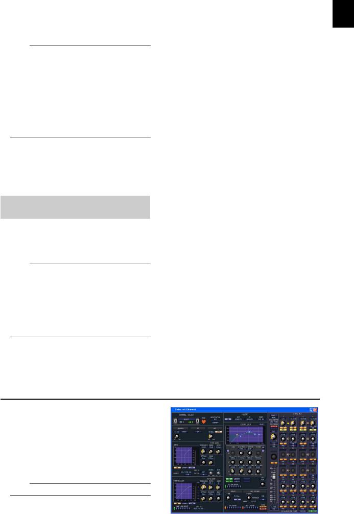
7 Using the Selected Channel section..... |
65 |
About the SELECTED CHANNEL section .......................... |
65 |
Items in the SELECTED CHANNEL section ....................... |
65 |
GROUP ........................................................................................ |
65 |
CHANNEL SELECT ................................................................... |
66 |
DELAY ......................................................................................... |
66 |
GAIN/ATTENUATION/ø (Gain / Attenuation / Phase) ........ |
67 |
NOISE GATE............................................................................... |
67 |
STEREO ....................................................................................... |
68 |
COMPRESSOR ........................................................................... |
68 |
HPF (High Pass Filter)................................................................ |
69 |
EQUALIZER................................................................................ |
69 |
Operations in the SELECTED CHANNEL section .............. |
70 |
Selecting a channel and editing its parameters ......................... |
70 |
Compressor operations............................................................... |
71 |
Gate operations ........................................................................... |
72 |
EQ/HPF operations..................................................................... |
73 |
8 Input Patch / Output Patch operations .74 |
|
Changing the input patch settings .................................. |
74 |
Changing the output patch settings................................ |
75 |
Inserting an external device into a channel...................... |
77 |
Connecting an external device for insertion ............................. |
77 |
Patching the insert-out and insert-in ........................................ |
78 |
Directly outputting the signal of an input channel .......... |
80 |
6 |
PM5D/PM5D-RH V2 / DSP5D Owner’s Manual Table of Contents |
|
|

9 Grouping and linking............................ |
81 |
About DCA Groups and Mute Groups ............................. |
81 |
Items in the ASSIGN MODE section ................................. |
81 |
Items in the DCA strip...................................................... |
81 |
Using DCA Groups........................................................... |
82 |
Assigning channels to DCA groups ............................................ |
82 |
Controlling DCA groups............................................................. |
83 |
Using mute groups .......................................................... |
83 |
Assigning channels to mute groups............................................ |
83 |
Controlling mute groups............................................................. |
84 |
Using the Mute Safe function ..................................................... |
84 |
Using EQ Link and Compressor Link ................................ |
85 |
10 Scene memory.................................... |
87 |
About scenes ................................................................... |
87 |
Items in the SCENE MEMORY section .............................. |
88 |
Using scene memories ..................................................... |
89 |
Storing a scene.............................................................................. |
89 |
Recalling a scene........................................................................... |
90 |
Using PREVIEW mode ...................................................... |
90 |
Using the Auto Store function.......................................... |
91 |
Using the Direct Recall function ....................................... |
91 |
Using the Selective Recall function................................... |
92 |
Using the Recall Safe function.......................................... |
94 |
Using the Fade function................................................... |
95 |
Using the Tracking Recall function ................................... |
96 |
Using the Global Paste function ....................................... |
97 |
11 Monitor and Cue................................ |
99 |
About the MONITOR and CUE sections........................... |
99 |
Using the Monitor function ........................................... |
100 |
Items in the MONITOR section............................................... |
100 |
Monitoring a signal.................................................................... |
101 |
Using the Cue/Solo functions ........................................ |
102 |
Items in the CUE section........................................................... |
102 |
About CUE mode and SOLO mode......................................... |
102 |
Cue and Solo groups.................................................................. |
103 |
Using the Cue function ............................................................. |
104 |
Using the Solo function............................................................. |
104 |
12 Talkback and Oscillator.................... |
105 |
About the TALKBACK/OSCILLATOR sections.................. |
105 |
Items in the TALKBACK/OSCILLATOR sections.................. |
105 |
Using talkback ............................................................... |
106 |
Using the oscillator ........................................................ |
107 |
13 Meters............................................... |
108 |
Items in the meter section ............................................. |
108 |
Switching the meter display........................................... |
108 |
Switching the metering point ........................................ |
109 |
Specifying the metering point for input channels ................... |
109 |
Specifying the metering point for output channels ................ |
109 |
Viewing the gain reduction of the internal gates and |
|
compressors....................................................... |
110 |
Viewing the gain reduction for input channels ....................... |
110 |
Viewing the gain reduction for output channels..................... |
110 |
14 Effects ............................................... |
111 |
About the internal effects............................................... |
111 |
Using an internal effect via a MIX bus ............................ |
112 |
Inserting an internal effect into a channel ...................... |
113 |
Basic operations in the effect screen .............................. |
114 |
Recalling settings from the effect library.................................. |
114 |
Editing the effect parameters .................................................... |
115 |
Storing settings in the effect library .......................................... |
115 |
Using the Tap Tempo function ...................................... |
116 |
Using the Freeze effect................................................... |
117 |
15 Graphic EQ and Parametric EQ ....... |
118 |
Patching the GEQ modules............................................ |
118 |
Expanding the GEQ modules......................................... |
119 |
Basic graphic EQ operations .......................................... |
119 |
Controlling the graphic EQ from the display ......................... |
119 |
Controlling the graphic EQ from the DCA section................ |
120 |
Basic parametric EQ operations ..................................... |
121 |
Controlling the parametric EQ from the display.................... |
121 |
Controlling the parametric EQ from the SELECTED |
|
CHANNEL section.......................................................... |
122 |
16 Remote control ................................ |
123 |
MIDI on the PM5D ........................................................ |
123 |
Using program changes to control events ..................... |
123 |
Using control changes to control events........................ |
125 |
Using the MIDI Remote function ................................... |
127 |
Assigning MIDI messages to controllers ................................. |
127 |
Using MIDI remote channels................................................... |
131 |
Transmitting MIDI events when you switch scenes........ |
132 |
Using GPI (General Purpose Interface) ........................... |
133 |
Using GPI IN ............................................................................. |
133 |
Calibrating the GPI IN ports .................................................... |
135 |
Using GPI OUT......................................................................... |
136 |
17 Using memory cards........................ |
138 |
Using memory cards with the PM5D ............................. |
138 |
Saving files to a memory card........................................ |
138 |
Loading files from a memory card ................................. |
140 |
18 Surround pan ................................... |
142 |
About surround pan ...................................................... |
142 |
Bus configuration and operation in surround mode ...... |
143 |
About the surround buses ........................................................ |
143 |
How the MIX section will operate ........................................... |
143 |
Basic settings for surround buses ................................... |
144 |
Controlling surround pan .............................................. |
145 |
Notes regarding surround pan ...................................... |
147 |
19 Other functions................................ |
148 |
Using the user defined keys ........................................... |
148 |
Items in the USER DEFINED section ..................................... |
148 |
Assigning functions to the User Defined keys ........................ |
148 |
Executing functions assigned to the User Defined keys ......... |
149 |
Using the FADER MODE section .................................... |
149 |
Items in the FADER MODE section........................................ |
149 |
Assigning the FADER MODE section layer ............................ |
149 |
Switching the FADER MODE section layer............................ |
150 |
Locking the PM5D (Security functions).......................... |
151 |
Setting the System Password or Console Password................ |
151 |
Using Parameter Lock or Console Lock.................................. |
152 |
Using cascade connections ............................................ |
153 |
Example of cascade connections between the PM5D and |
|
DSP5D.............................................................................. |
153 |
Example of cascade connections between PM5D units ......... |
153 |
Specifying the DSP5D’s machine ID number......................... |
153 |
Basic settings for cascade connection ...................................... |
154 |
Selecting the buses used for cascade connection .................... |
156 |
Connecting the PM5D to your computer via USB ......... |
158 |
Caution when using the USB TO HOST connector .............. |
158 |
Connecting the DSP5D to your computer via Ethernet . 159 |
|
Initializing the PM5D’s internal memory........................ |
160 |
Initializing the DSP5D’s internal memory....................... |
160 |
Adjusting the faders and input/output gain |
|
(Calibration) ...................................................... |
161 |
Calibrating the faders................................................................ |
161 |
Adjusting the analog input gain (PM5D-RH model only).... |
162 |
Adjusting the output gain......................................................... |
162 |
PM5D/PM5D-RH V2 / DSP5D Owner’s Manual Table of Contents |
7 |
|
|

Table of Contents — Reference section
Information shown in the display.......... |
163 |
Upper part of the display (always visible)....................... |
163 |
Main area of the display ................................................ |
164 |
Lower part of the display (always visible) ....................... |
164 |
Function menu........................................ |
165 |
Global functions...................................... |
166 |
EFFECT functions ........................................................... |
166 |
EFFECT PARAM (Effect parameter) screen ........................... |
166 |
EFFECT ASSIGN screen............................................................ |
168 |
EFFECT LIBRARY screen ......................................................... |
169 |
PLUG-IN screen......................................................................... |
170 |
GEQ function................................................................. |
170 |
GEQ PARAM (GEQ parameter) screen .................................. |
170 |
GEQ ASSIGN screen ................................................................. |
173 |
GEQ LIBRARY screen ............................................................... |
174 |
SCENE function ............................................................. |
175 |
SCENE screen............................................................................. |
175 |
EVENT LIST screen................................................................... |
177 |
SELECTIVE RECALL screen .................................................... |
180 |
RECALL SAFE screen ................................................................ |
182 |
FADE TIME screen.................................................................... |
184 |
TRACKING RECALL screen .................................................... |
186 |
GLOBAL PASTE screen ............................................................ |
187 |
MIDI REMOTE function ................................................. |
188 |
MIDI SETUP screen .................................................................. |
188 |
MIDI PGM CHANGE (MIDI program change) screen ........ |
190 |
MIDI CTRL CHANGE (MIDI control change) screen .......... |
191 |
MIDI REMOTE screen.............................................................. |
192 |
GPI screen................................................................................... |
194 |
FADER START screen............................................................... |
196 |
TRANSPORT screen ................................................................. |
198 |
DME CONTROL screen ........................................................... |
199 |
UTILITY function ............................................................ |
204 |
PREFERENCE 1/2 screens ........................................................ |
204 |
USER DEFINE screen................................................................ |
208 |
SAVE screen ............................................................................... |
211 |
LOAD screen .............................................................................. |
215 |
FADER ASSIGN screen ............................................................. |
217 |
SECURITY screen...................................................................... |
218 |
SYS/W.CLOCK function ................................................. |
219 |
WORD CLOCK screen.............................................................. |
219 |
MIXER SETUP screen ............................................................... |
221 |
CASCADE screen....................................................................... |
226 |
HA (Head Amp) screen............................................................. |
228 |
OUTPUT PORT ATT (Output port attenuation) screen ...... |
229 |
DITHER screen .......................................................................... |
229 |
HA LIBRARY screen.................................................................. |
230 |
METER function ............................................................. |
231 |
INPUT METER screen .............................................................. |
231 |
OUTPUT METER screen.......................................................... |
232 |
INPUT GR (Input Gain Reduction) screen............................. |
233 |
OUTPUT GR (Output Gain Reduction) screen ..................... |
234 |
MON/CUE function ....................................................... |
234 |
TALKBACK screen .................................................................... |
234 |
OSCILLATOR screen ................................................................ |
236 |
2TR I/O screen ........................................................................... |
237 |
MONITOR screen ..................................................................... |
238 |
CUE/SOLO screen ..................................................................... |
240 |
Output functions .................................... |
243 |
OUTPUT PATCH function .............................................. |
243 |
OUTPUT PATCH screen ......................................................... |
243 |
INSERT PATCH screen............................................................ |
244 |
INSERT POINT screen............................................................. |
246 |
NAME screen............................................................................. |
247 |
OUTPUT PATCH LIBRARY screen ....................................... |
247 |
OUTPUT INSERT function.............................................. |
248 |
INSERT IN MIX 1-24 screen ................................................... |
248 |
INSERT IN MATRIX/STEREO/MONITOR screen .............. |
248 |
HA LIBRARY screen ................................................................. |
249 |
OUTPUT EQ function .................................................... |
250 |
EQ PARAM (EQ Parameter) screen........................................ |
250 |
MIX 1-24 screen ........................................................................ |
251 |
MATRIX/STEREO screen ........................................................ |
251 |
OUTPUT EQ LIBRARY screen................................................ |
252 |
OUTPUT COMP function............................................... |
253 |
COMP PARAM (Compressor parameter) screen.................. |
253 |
MIX 1-24 screen ........................................................................ |
255 |
MATRIX/STEREO screen ........................................................ |
255 |
COMP LIBRARY (Compressor library) screen...................... |
256 |
OUTPUT DELAY function ............................................... |
257 |
MIX 1-24 screen ........................................................................ |
257 |
MATRIX/STEREO screen ........................................................ |
257 |
OUTPUT DCA/GROUP function..................................... |
258 |
DCA GROUP ASSIGN screen ................................................. |
258 |
MUTE GROUP ASSIGN screen .............................................. |
259 |
EQ LINK ASSIGN screen ......................................................... |
260 |
COMP LINK ASSIGN (Compressor link assign) screen ....... |
261 |
MATRIX/ST function...................................................... |
262 |
MATRIX/ST ROUTING screen............................................... |
262 |
MIX to MATRIX VIEW screen................................................ |
264 |
LCR screen ................................................................................. |
267 |
SURR SETUP screen................................................................. |
268 |
OUTPUT VIEW function ................................................. |
270 |
CH VIEW (Channel view) screen............................................ |
270 |
SIGNAL FLOW screen ............................................................. |
272 |
FADER VIEW screen ................................................................ |
273 |
CH JOB (Channel job) screen.................................................. |
274 |
OUTPUT CH LIBRARY screen ............................................... |
275 |
8 |
PM5D/PM5D-RH V2 / DSP5D Owner’s Manual Table of Contents |
|
|

Input functions ........................................ |
277 |
INPUT PATCH function .................................................. |
277 |
INPUT PATCH screen .............................................................. |
277 |
DIRECT OUT PATCH screen.................................................. |
278 |
INSERT PATCH screen ............................................................ |
279 |
INSERT/DIRECT OUT POINT screen ................................... |
281 |
NAME screen ............................................................................. |
282 |
INPUT PATCH LIBRARY screen ............................................ |
283 |
INPUT HA/INSERT function............................................ |
283 |
CH 1-24 (Input channel 1-24) screen ...................................... |
283 |
CH 25-48 (Input channel 25-48) screen .................................. |
283 |
STIN/FXRTN (ST IN/FXRTN channel) screen ...................... |
283 |
INSERT 1-24 screen................................................................... |
284 |
INSERT 25-48 screen................................................................. |
284 |
INSERT STIN screen ................................................................. |
284 |
HA LIBRARY screen.................................................................. |
285 |
INPUT ø/EQ function ..................................................... |
286 |
EQ PARAM (EQ parameter) screen ........................................ |
286 |
EQ 1-24 screen ........................................................................... |
287 |
EQ 25-48 switch ......................................................................... |
287 |
EQ STIN/FXRTN screen ........................................................... |
287 |
ø/ATT 1-48 (Phase/Attenuation 1-48) screen ......................... |
288 |
ø/ATT STIN/FXRTN (Phase/Attenuation STIN/FXRTN) |
|
screen ................................................................................ |
288 |
INPUT EQ LIBRARY screen .................................................... |
289 |
INPUT GATE/COMP function......................................... |
289 |
GATE PARAM (Gate parameter) screen ................................. |
289 |
COMP PARAM (Compressor parameter) screen .................. |
291 |
CH 1-12 (Input channel 1–12) screen ..................................... |
293 |
CH 13-24 (Input channel 13–24) screen ................................. |
293 |
CH 25-36 (Input channel 25–36) screen ................................. |
293 |
CH 37-48 (Input channel 37–48) screen ................................. |
293 |
ST IN (ST IN channel) screen................................................... |
293 |
GATE LIBRARY screen ............................................................. |
294 |
COMP LIBRARY (Compressor library) screen ...................... |
295 |
INPUT DELAY function ................................................... |
295 |
CH 1-24 (Input channel 1–24) screen ..................................... |
295 |
CH 25-48 (Input channel 25–48) screen ................................. |
295 |
ST IN (ST IN channel) screen................................................... |
295 |
INPUT DCA/GROUP function......................................... |
296 |
DCA GROUP ASSIGN screen .................................................. |
296 |
MUTE GROUP ASSIGN screen............................................... |
297 |
EQ LINK ASSIGN screen.......................................................... |
298 |
COMP LINK ASSIGN (Compressor link assign) screen ....... |
299 |
PAN/ROUTING function ................................................ |
299 |
CH to MIX (Channel to mix) screen ....................................... |
299 |
MIX SEND VIEW screen .......................................................... |
305 |
FIX ASSIGN VIEW screen ........................................................ |
307 |
LCR screen.................................................................................. |
308 |
SURR PARAM (Surround parameter) screen......................... |
309 |
SURR VIEW (Surround view) screen ...................................... |
310 |
M/S screen .................................................................................. |
311 |
INPUT VIEW function ..................................................... |
311 |
CH VIEW (Channel view) screen ............................................ |
311 |
SIGNAL FLOW screen .............................................................. |
313 |
FADER VIEW screen................................................................. |
314 |
CH JOB screen ........................................................................... |
314 |
INPUT CH LIBRARY (Input channel library) screen............ |
316 |
Appendices.............................................. |
|
317 |
EQ Library List................................................................ |
|
317 |
GATE Library List............................................................ |
|
318 |
Compressor Library List ................................................. |
|
319 |
Dynamics Parameters .................................................... |
|
321 |
GATE section............................................................................. |
|
321 |
COMP section ........................................................................... |
|
322 |
Effect Library List............................................................ |
|
324 |
Effects Parameters.......................................................... |
|
325 |
Effects and tempo synchronization ......................................... |
|
336 |
Scene Memory/Effect Library to Program Change Table |
.. 337 |
|
Parameters that can be assigned to control changes ..... |
341 |
|
Control change parameter assignments ........................ |
|
343 |
NRPN parameter assignments ....................................... |
|
360 |
Channel Library List ....................................................... |
|
364 |
List of parameters available for Pair, Recall Safe or |
|
|
OUTPUT ISOLATION operation ......................... |
|
365 |
MIDI Data Format.......................................................... |
|
368 |
Warning Messages......................................................... |
|
377 |
Error Messages............................................................... |
|
379 |
Troubleshooting ............................................................ |
|
380 |
General Specifications.................................................... |
|
381 |
PM5D/PM5D-RH..................................................................... |
|
381 |
DSP5D........................................................................................ |
|
383 |
Input/output characteristics........................................... |
|
384 |
Electrical characteristics ................................................. |
|
389 |
PM5D/PM5D-RH..................................................................... |
|
389 |
DSP5D........................................................................................ |
|
391 |
Other Functions............................................................. |
|
393 |
Pin Assignment.............................................................. |
|
394 |
Dimensions.................................................................... |
|
395 |
MIDI Implementation Chart .......................................... |
|
396 |
Index ............................................................................. |
|
397 |
PM5D/PM5D-RH Block Diagram ................... |
End of Manual |
|
DSP5D Block Diagram ................................... |
End of Manual |
|
PM5D Level Diagram..................................... |
End of Manual |
|
PM5D-RH Level Diagram ............................... |
End of Manual |
|
DSP5D Level Diagram ................................... |
End of Manual |
|
•The illustrations and screen displays as shown in this Owner’s Manual are for instructional purposes only, and may be different from the ones on your device.
•The company names and product names in this Owner’s Manual are the trademarks or registered trademarks of their respective companies.
PM5D/PM5D-RH V2 / DSP5D Owner’s Manual Table of Contents |
9 |
|
|

Operating section
1 Introduction
Thank you
Thank you for purchasing the Yamaha PM5D digital mixing console and/or Yamaha DSP5D digital mixing system. In order to take full advantage of the PM5D/DSP5D’s superior functionality and enjoy years of trouble-free use, please read this manual before you begin using the product. After you have read the manual, keep it in a safe place.
An overview of the PM5D system
The PM5D is an expandable digital mixing console with the following features.
Full digital SR mixing system
The PM5D is a full-digital SR mixing console that takes advantage of cutting-edge digital audio processing technology. 24-bit linear AD/DA converters are used to deliver up to 110 dB of dynamic range and amazing sound quality. As input channels, it provides 48 monaural channels, four stereo channels, and four stereo channels for effect return. As output channels, it provides 24 MIX channels, eight MATRIX channels, and two STEREO channels. The PM5D can be used in a wide range of applications. You can assign desired channels to be controlled by the eight DCA faders on the panel, and use them as group faders.
PM5D model and PM5D-RH model
In addition to the standard PM5D model that provides manual control of the head amp for each input, the PM5D-RH model is also available, providing programmable control of head amp input sensitivity and phantom power settings. You can choose the model appropriate for your situation and budget.
Cutting-edge user interface
For the input channels and STEREO A/B channels, dedicated channel strips are provided where you can operate the fader, pan, cue, and on/off controls. For MIX channels and MATRIX channels, encoders allow you to control the send level and master level. The PM5D allows quick and intuitive operation just as on an analog mixer. In addition, you can use the SELECTED CHANNEL section to manually control the principal parameters (delay, EQ, gate, compressor) of the desired channel.
Eight effect modules / Twelve graphic EQ modules
Eight high-quality multi-effect modules are built in. Effects such as reverb, delay, multiband compressor, and various modulation effects can be routed via internal buses or inserted into the desired channel. 31-band graphic EQ (alternatively, 8-band parametric EQ) can also be inserted into any channel or any output.
Add-On effects provided as standard
As effect types, the channel strip package (COMP276/276S, COMP260/260S, EQ601), master strip package (OPEN DECK), and reverb package (REV-X) are provided as standard.
Scene memories and libraries
Mix parameters and internal effect settings can be stored in memory as up to 500 scenes for immediate recall. Effects, input/output patching, input channel/output channel settings, internal head amp (PM5D-RH model only) or external head amp settings can be stored in various libraries, independently of scenes.
Digital cascade connection
Up to four PM5D units, or one PM5D and one Yamaha DM2000/02R96 unit, can be cascade-connected to share buses in the digital domain. In particular when PM5D units are cascaded together, operations such as scene saving and recall can also be linked. DME64N can also be used as inserts or as extended signal processors via a cascade connection.
Surround panning
Surround pan functionality allows multi-channel playback systems to be used, letting you place the signal of an input channel in two-dimensional space, or move the sound image forward/backward and left/right. 3-1ch, 5.1ch, and 6.1ch surround modes are available.
I/O card expansion
The rear panel provides four slots in which separately sold mini-YGDAI cards can be installed. AD cards, DA cards, or digital I/O cards can be installed in these slots to add inputs and outputs.
Expansion via the DSP5D
A maximum of two DSP5D digital mixing systems can be cascade-connected to a PM5D to expand the inputs and outputs. You can also connect a Yamaha DCU5D digital cabling unit between the PM5D and DSP5D, and locate the DSP5D remotely.
10 |
PM5D/PM5D-RH V2 / DSP5D Owner’s Manual Operating section |
|
|
Differences between the PM5D model and the PM5D-RH model
The PM5D is available as the standard PM5D model or as the PM5D-RH model which allows internal head amp settings to be programmed. These models differ as follows.
PM5D model |
PM5D-RH model |
• Head amp adjustments (input sensitivity settings, |
• Head amp adjustments (input sensitivity settings, |
phantom power (+48V) on/off) for the analog inputs |
phantom power (+48V) on/off) for the analog inputs |
(INPUT jacks 1–48, ST IN jacks 1–4) are performed |
are controlled from within the screen via software. For |
manually, using the controls of the top panel. |
this reason, the top panel does not have head amp con- |
|
trols; instead, LEDs showing the presence or absence of |
|
a signal are provided. Head amp settings can be saved |
|
in a library and recalled at any time. |
1
Introduction
•Insert jacks (INSERT IN/OUT jacks) for the monaural analog inputs (INPUT jacks 1–48) are provided on the rear panel, allowing external effect processors to be inserted in the analog domain.
•ST IN jacks 1–4 are only for line level.
•There is no +48V MASTER switch.
ST IN jacks 1–4 |
|
|
|
|
INPUT jacks 1–48 |
|||||||||
|
|
|
|
|
|
|
|
|
|
|
|
|
|
|
|
|
|
|
|
|
|
|
|
|
|
|
|
|
|
INSERT IN/OUT jacks 1–48
•Insert jacks for the analog inputs are not provided.
•ST IN jacks 1–4 support mic levels through line levels. Phantom power can also be supplied to ST IN jacks 1– 4.
•The +48V MASTER switch turns all phantom power (+48V) on/off.
ST IN jacks 1–4
INPUT jacks 1–48
PM5D/PM5D-RH V2 / DSP5D Owner’s Manual Operating section |
11 |
|
|

1 Introduction
About the channel structure of the PM5D
The PM5D provides the following input channels and output channels.
Input channels
This section processes input signals and sends them to the STEREO bus or MIX buses. There are three types of input channel, as follows.
•Input channels 1–48
These channels are used to process monaural signals. By default, the input signals from the monaural analog input jacks (INPUT jacks 1–48) are assigned to these channels.
•ST IN channels 1–4
These channels are used to process stereo signals. By default, the input signals from the stereo analog input jacks (ST IN jacks 1–4) are assigned to these channels.
•FX RTN channels 1–4
These channels are used mainly to process the return signals (stereo) from the internal effects. By default, the left/right output channels of internal effects 1 through 4 are assigned to these channels.
Hint
Signal assignments to the input channels can be changed as desired.
Output channels
This section mixes the signals sent from input channels etc., and sends them to the corresponding output jacks or output buses. There are three types of output channel, as follows.
•MIX channels 1–24
These channels process signals sent from input channels to MIX buses. In the initial state, output signals are assigned to MIX OUT jacks 1–24. These channels are used mainly for foldback or as sends to external effects. The signals of MIX channels 1–24 can also be sent to the STEREO bus or MATRIX buses.
•MATRIX channels 1–8
These process the signals sent from MIX channels or STEREO A/B channels to MATRIX buses, and output them from the MATRIX OUT jacks. This allows MIX channels or STEREO A/B channels to be mixed at the desired balance for output.
•STEREO A/B channels
These process the signals sent from input channels or MIX channels, and output them to STEREO OUT jacks A/B. These channels are used as the main stereo outputs. Normally, the same signal is sent from the STEREO A and B channels. However, it is also possible to use the STEREO B channel as the center channel for three-channel L/C/R playback.
About the DSP5D
The DSP5D is a digital signal processing (DSP) system expanding the inputs and outputs of the PM5D.
•Its audio processing capability is equivalent to that of the PM5D-RH. As analog audio input/output jacks, it provides INPUT jacks 1–48, ST IN jacks 1–4, and OMNI OUT jacks 1–24.
•Up to two DSP5D units can be cascade-connected to one PM5D. By connecting it with DSP5D units, the PM5D system can be expanded to a maximum of 168 channels of input (144 channels + 12 ST).
•By switching the control target on the PM5D, the DSP5D can be seamlessly controlled in the same way as the PM5D itself.
•You can use DSP5D Editor application software to remotely control and edit the parameters of the DSP5D. Only Windows computers are supported.
•The DSP5D can be connected to a Yamaha DCU5D digital cabling unit and placed on stage, and operated remotely from the PM5D.
•The front panel provides two slots in which you can install separately sold mini-YGDAI cards to add inputs and outputs in a variety of digital formats.
Differences with the PM5D
Connectors and interfaces not found on the DSP5D
•INSERT IN/OUT jacks, MIX OUT jacks, LAMP jacks, MONITOR OUT jacks, CUE OUT jacks, STEREO OUT A/B jacks, MATRIX OUT jacks, 2TR IN ANALOG jacks, TIME CODE INPUT jack, USB TO HOST connector, GPI connector, RS422 REMOTE connector, HA REMOTE connector, MIDI IN/THRU/OUT connectors, 2TR OUT DIGITAL jack, 2TR IN DIGITAL jack, SLOT 3–4, MEMORY CARD slot, MOUSE connector, KEYBOARD connector, PHONES jack
•Controllers such as faders, display devices such as
meters. LCD display, +48V MASTER switch (PM5DRH), 75Ω ON/OFF switch
Connectors and interfaces found only the DSP5D
•OMNI OUT jacks, CASCADE IN/OUT RJ-45 connectors, NETWORK connector, AC IN connector
•POWER switch, mode switch, FAN switch
About the connectors: Since the DSP5D does not have the functionality for the connectors with which DSP5D is not equipped, these functions and connectors are not shown in the screen of the PM5D or DSP5D Editor.
12 |
PM5D/PM5D-RH V2 / DSP5D Owner’s Manual Operating section |
|
|
About the interface: Since the DSP5D does not have controllers such as faders or the LCD display, it is operated from the PM5D or DSP5D Editor.
Note
•The explanations in chapter 5 and following of this Owner’s Manual are based on the functionality and operating procedures of the PM5D. Supplementary explanations regarding the DSP5D are added only in cases where there is a significant difference in functionality or operating procedure.
However, in cases where it is obvious that the abovedescribed differences would make clear differences in operation or in the on-screen display, explanations for the DSP5D will be omitted.
•There are some differences between the PM5D and DSP5D in the I/O cards that are supported. For the most recent information regarding I/O cards, refer to the following Yamaha website.
http://www.yamahaproaudio.com/
Connection to a computer
The PM5D can be connected to a computer via a USB cable from its USB TO HOST connector, but the DSP5D can be connected to a computer via an Ethernet CAT5 cable from its NETWORK connector.
Regarding cascade connections between the PM5D and DSP5D
By bi-directionally cascade-connecting the PM5D and DSP5D, you can share MIX buses 1–24, STEREO A/B buses, and CUE buses.
For details on cascade connections, refer to p.153.
Note
•Cascade connection with the DSP5D is possible only for PM5D V2.0 or later. If you’re using earlier version than V2.0, you will need to upgrade to PM5D V2.0 or later. You can download the most recent firmware from the following Yamaha website.
http://www.yamahaproaudio.com/
•Connectors and interfaces not found on the DSP5D cannot be controlled from the PM5D. For example, the MONITOR [LEVEL] and MONITOR [PHONES] knobs found on the PM5D’s top panel are always operated at the level of the PM5D.
Controlling the DSP5D
•As the target of control from the PM5D’s panel and screen, you can recall machine #1 (PM5D), machine #2
(first DSP5D), or machine #3 (second DSP5D) as desired. For details on operation, refer to p.153.
•Functions assigned to the user-defined keys or the FADER MODE section can be used to select the DSP5D as the target machine to be operated ( p.148, 149). Operations can be performed from the panel of the PM5D itself or from DSP5D Editor connected to the DSP5D.
Operation when cascade-connected
•Output channels
In general, operations for the output channels of cas- cade-connected buses will be linked between machines. (You can also specify that they not be linked.) This means that you can operate the system as if it were a single console with an expanded number of inputs. However, since the inserts to output channels will also be duplicated, inserted GEQ modules and effects may also be consumed in duplicate or triplicate. (Separate GEQ modules or effects are inserted into the linked buses on each machine.)
•Scene memories and libraries
Scene memory and library data is stored on each machine. When a scene or a library associated with a scene is stored or recalled, the same scene/library number will be stored/recalled on all machines. When the cascade-connection becomes active, the PM5D’s library data not associated with a scene will be sent to each DSP5D to synchronize the libraries. The data on cascade-connected machines can also be saved together to a memory card.
•Effects
The DSP5D provides GEQ modules and effects that are equivalent to those on the PM5D, but since the connections between machines are bus cascade connections, inserts into input channels are limited to being within each machine.
•DCA groups / Mute groups
These will operate in tandem for cascade-connected PM5D/DSP5D machines. ( p.156)
•CH JOB function
Channel copy operations between the PM5D/DSP5D can be performed from the PM5D front panel. However, channels can be moved using the INPUT VIEW function only within each machine. ( p.274, 314)
About PM5D Editor and DSP5D Editor
These programs are application software for operating the PM5D/DSP5D’s functionality from a computer. You can use this software to remotely control and edit the parameters of the PM5D/DSP5D.
The USB-MIDI driver (for the PM5D) or DME-N Network driver (for the DSP5D) required for connection with a computer, as well as the PM5D/DSP5D editor, can be downloaded from the following Yamaha website. http://www.yamahaproaudio.com/
Note
DSP5D Editor supports only Windows computers.
1
Introduction
PM5D/PM5D-RH V2 / DSP5D Owner’s Manual Operating section |
13 |
|
|

1 Introduction
Firmware versions
You can download the most recent firmware from the following Yamaha website. http://www.yamahaproaudio.com/
For either the PM5D or the DSP5D, you can check the firmware version in the UTILITY function PREFERENCE 2 screen ( p.207).
Major new functionality in PM5D firmware V2.0
The major new functionality and improvements that were added in conjunction with the upgrade to firmware V2.0 are as follows.
Basic functionality and panel operations
•You can now control the DSP5D from the PM5D’s panel. ( p.153)
•On/off operations of the channel selected in the FADER MODE section can now be operated from the DCA [MUTE] key.
•Even if the FADER [FLIP] key is on, you can now use the encoders to control the panning of the signal sent to the MIX buses, the head amp gain, or the attenuators. ( p.49)
•If there is no vacant library number when you store the selected scene as NEW, it will now be impossible to save the scene; this prevents an existing library item from being overwritten.
•Remote control of the DME64N/24N (firmware V2.0 and later) is now faster. In particular, operation is faster when connected via an MY16-C or MY16-CII card (supported from V1.2).
•As parameters that can be operated in the screen, MONITOR LEVEL and CUE LEVEL have been added. You can now assign these to the faders of the DCA strip so that the monitor or cue levels can be adjusted.
( p.149)
•When you insert a GEQ in the GEQ PARAM screen, insert-in will automatically be turned on for that channel, and will be automatically turned off when you remove the GEQ.
SCENE functions
•In the SCENE screen, you can now specify “read-only” scenes that will not be overwritten when you load scenes from a memory card. ( p.175)
•In the SCENE screen, a DELAY field has been added, allowing you to specify the timing of the program change or MIDI events that are transmitted when the scene is recalled. ( p.175)
•In the SELECTIVE RECALL screen and the RECALL SAFE screen, the ON parameter has been added as a channel parameter that can be included in or excluded from recall operations. ( p.180, 182)
•In the SELECTIVE RECALL screen and RECALL SAFE screen, separately from the conventional Recall Safe functionality, an OUTPUT ISOLATION field has been added, so that output channels and parameters to be excluded from recall operations can be stored in SETUP memory (which is not affected by memory card load operations). ( p.180, 182)
EFFECT functions
•Add-On Effects (COMP276/276S, COMP260/260S, EQ601, OPEN DECK) and DE-ESSER have been added.
•A DSP CONFIGURATION option has been added to the EFFECT ASSIGN screen and to the GEQ function GEQ ASSIGN screen, allowing internal effects 1–8 to be used as graphic EQ or parametric EQ.
( p.168, 173)
•When the panel [SEL] key is pressed in the EFFECT PARAM screen, or when a [SEL] key is turned on via a linking setting, the effect module inserted in that channel will automatically be selected.
•If you’ve used the tap tempo function to specify the tempo in the EFFECT PARAM screen and then edited the DELAY parameter, the tempo will now stay unchanged.
GEQ functions
•Options have been added to the GEQ PARAM screen, allowing you to switch a graphic EQ to a parametric EQ. ( p.170)
•Not only when the panel [SEL] key is pressed in the GEQ PARAM screen but also when a [SEL] key is turned on via a linking setting, the GEQ module inserted in that channel will automatically be selected.
SYS/W.CLOCK functions
•In the MIXER SETUP screen, a VIRTUAL SOUNDCHECK button has been added, allowing you to temporarily switch the input signals without affecting the scene memory (input patching). For example, this allows you to perform a sound check using prerecorded material played back by a DAW connected to a slot, instead of the analog input material received via the INPUT jacks. ( p.221)
•In the OUTPUT ATT PORT screen, a ø (phase) button has been added, allowing you to switch the phase between normal and reverse for each output channel or I/O channel output port.
UTILITY functions
•In the PREFERENCE 1 screen, a DCA MUTE TARGET option has been added, allowing you to specify that the DCA [MUTE] key will mute the send to the MIX bus. ( p.205)
•In the PREFERENCE 1 screen, an ATT OPERATION ON PANEL option has been added, allowing you to prevent the panel encoders from operating the attenuators. ( p.206)
•In the PREFERENCE 1 screen, a MIX SEL/ENCODER MODE LINK option has been added, allowing you to
14 |
PM5D/PM5D-RH V2 / DSP5D Owner’s Manual Operating section |
|
|

link selection of MIX channels with selection of MIX SEND SELECT keys. ( p.206)
•In the USER DEFINE screen, functions such as DSP5D CONTROL and ENCODER MODE KEY have been added to the functions that can be assigned to userdefined keys. ( p.208)
•In the FADER ASSIGN screen, options have been added, allowing you to use the STEREO/DCA strip section to control the monitor/cue level and on/off status. ( p.217)
•In the FADER ASSIGN screen, you can now assign the desired channels of the DSP5D as well. ( p.217)
•In the SECURITY screen, a LOAD LOCK function has been added, allowing you to disable loading for each type of file. ( p.218)
•In the SECURITY screen, a RECALL LOCK option has been added, allowing you to lock parameters so that they will not be changed when a scene or library is recalled. ( p.218)
Input/output functions
•In the OUTPUT PATCH function OUTPUT PATCH screen, you can now change the patching of output channels to MIX OUT jacks 1–24. ( p.243)
•In the OUTPUT PATCH function INSERT POINT screen and the INPUT PATCH function INSERT/ DIRECT OUT POINT screen, a SET ALL button and CLEAR ALL button have been added, allowing you to turn all channels on/off in a single operation.
( p.246, 281)
•In the OUTPUT PATCH function, a NAME screen has been added, allowing you to assign names to output channels for display in various screens (supported from V1.2). ( p.247)
•In the INPUT VIEW function CH JOB screen, channel settings can now be moved as well as copied. ( p.314)
•In the INPUT PATCH function INSERT/DIRECT OUT POINT screen, PRE ATT has been added as a direct output transmit location. ( p.282)
•In the PAN/ROUTING function MIX SEND VIEW screen, the send position (PRE/POST) of the signal sent to the MIX bus is now indicated by the color of the bar graph. ( p.306)
•You can now set a Q of up to 16 for the parametric EQ in the input channels, output channels, and GEQ modules.
•You can now set a threshold level of down to –72 dB for an input channel GATE.
Regarding word clock synchronization
The signal used to synchronize digital audio signal processing is called “word clock.” Normally, one device transmits a reference word clock signal, and the other devices receive this word clock signal and synchronize to it.
In order to transmit or receive digital audio signals to or from an external device via the PM5D/DSP5D’s digital input/output jacks or via a digital I/O card installed in a slot, the word clock must be synchronized between the devices. Be aware that if the word clock is not synchronized, the signals will not be transmitted correctly, and unpleasant noise will occur.
Hint
•For details on synchronizing the word clock of the PM5D/ DSP5D and external devices, refer to the explanation of word clock in Operating section “Chapter 4. Connections and setup” ( p.38), and to the Reference Section “WORD CLOCK screen” ( p.219).
•As an exception, digital signals that are not synchronized with the PM5D/DSP5D can be input via a digital I/O card that contains a sampling rate converter, or via the 2TR IN/ OUT DIGITAL jacks.
How this manual is organized
This owner’s manual is divided into the following three sections.
Operating section
This section explains the items on the front and rear panels, connections and setup, and how to operate the PM5D’s basic functionality. In particular if you have not operated a digital console before, we recommend that you read chapters 2 through 7 first.
Reference section
This section explains the functionality and operation for all of the PM5D’s screens. Refer to this section when you want to learn about the items in the screens.
Appendices
This contains various information such as library lists, parameter lists for the internal effects, the MIDI data format, and lists of warning messages and error messages.
Conventions in this manual
In this manual, non-locking panel switches that you press are called “keys,” and those that change their on/off status when you push them in (locking types) are called “switches.” Of the control knobs on the panel, those that turn from a minimum value to a maximum value are called “knobs,” while those that turn endlessly are called “encoders.”
Controls located on the panel are enclosed in square brackets [ ] (e.g., [CUE] key, [PAD] switch) in order to distinguish them from the buttons and knobs displayed in the screen. For some controls, the section name is listed before the [ ] (e.g., CH [ON] key, EQ [FREQUENCY] encoder).
Unless otherwise specified, references to the PM5D apply to both the PM5D model and the PM5D-RH model. If specifications differ between the PM5D model and the PM5D-RH model, such differences will be noted each time they occur.
1
Introduction
PM5D/PM5D-RH V2 / DSP5D Owner’s Manual Operating section |
15 |
|
|

2 Top, front, and rear panels
2 Top, front, and rear panels
This chapter explains the names and functions of each part of the PM5D/DSP5D. Details for each section of the top panel are explained in subsequent chapters of this operating section; refer to the appropriate chapter for more information.
Top panel
(PM5D model)
1 |
AAD IN section (PM5D model)
In this section you can adjust the sensitivity of the analog signals being input from the rear panel INPUT jacks 1–48 and ST IN jacks 1–4, and switch pad, insert, and phantom power (+48 V) on/off ( p.43).
(PM5D-RH model)
2 |
BAD IN section (PM5D-RH model)
This area indicates the presence, peak level, and phantom power (+48V) on/off status of the input signal from rear panel INPUT jacks 1–48 and ST IN jacks 1– 4.
Hint
For the PM5D-RH model, input sensitivity and phantom power on/off are controlled by operations in the display ( p.44).
6 |
8 |
4 |
5 |
7 |
3 |
CINPUT channel strip section
This section controls the principal parameters for input channels 1–48 ( p.45).
DFADER FLIP/ENCODER MODE section
Here you can select the parameters controlled by the faders/encoders of the INPUT channel strip (3) ( p.48).
EMIX section
This section controls the on/off status and send level of the signals sent from input channels to MIX buses, and adjusts the master level of the MIX channels ( p.57).
FMATRIX section
This section controls the send level of the signals sent from MIX channels to MATRIX buses, and adjusts the master level of the MATRIX channels ( p.63).
GSELECTED CHANNEL section
In this section you can view and control the mix parameters for the currently selected input channel or output channel ( p.65).
HMeter section
This section contains peak level meters that indicate the input levels of input channels and the output levels of output channels and cue monitoring, as selected by key operations ( p.108).
16 |
PM5D/PM5D-RH V2 / DSP5D Owner’s Manual Operating section |
|
|

8 |
9 |
|
|
|
|
|
|
N |
O |
P |
|
R |
|
|
Q |
J |
|
|
R |
|
|
|
|
|
|
K |
M |
L T |
|
S |
IDisplay
This display shows the information you need to operate the PM5D, and lets you make system-wide settings and control mix parameters for input and output channels ( p.23).
Hint
You can adjust the angle of the display by moving the upper part of the display frame forward or backward.
Note
Before moving the PM5D, you must lower the display all the way back until it is fastened in place.
JFADER MODE section
Here you can select the combination of channels or DCA groups that will be controlled by the faders of the DCA strip section (K) ( p.149).
KDCA strip section
From this section you can control the channels assigned to DCA groups 1–8 ( p.81).
LST IN/FX RTN (Stereo in / Effect return) channel strip section
This section controls the principal parameters of ST IN channels 1–4 or FX RTN channels 1–4 ( p.47).
MSTEREO strip section
This section controls the principal parameters of the STEREO A/B channels ( p.61).
NSCENE MEMORY section
This section stores/recalls mix parameters as scene memories ( p.88). Mute operations for mute groups 1–8 are also performed in this section ( p.83).
OCUE/MONITOR section
This section selects the monitor source that is output from the MONITOR OUT jacks, and adjusts the levels. This section also determines the cue point and monitoring method that will be used when you press a [CUE] key for a channel ( p.99).
POSCILLATOR/TALKBACK section
This section switches the oscillator or talkback on/off, and adjusts the talkback level ( p.105).
QDISPLAY ACCESS section
This section selects the functions or screen shown in the display ( p.24).
RUSER DEFINED KEYS sections
This section executes the functions that have been assigned to the User Defined keys [1]–[25] ( p.148).
SData entry section
This section lets you move the pointer (the arrow displayed in the screen) or cursor (the red frame indicating a selection) in the display and edit the parameter value ( p.24).
TASSIGN MODE section
This section lets you assign mute groups and DCA groups for control from the panel ( p.81).
2
Top, front, and rear panels
PM5D/PM5D-RH V2 / DSP5D Owner’s Manual Operating section |
17 |
|
|
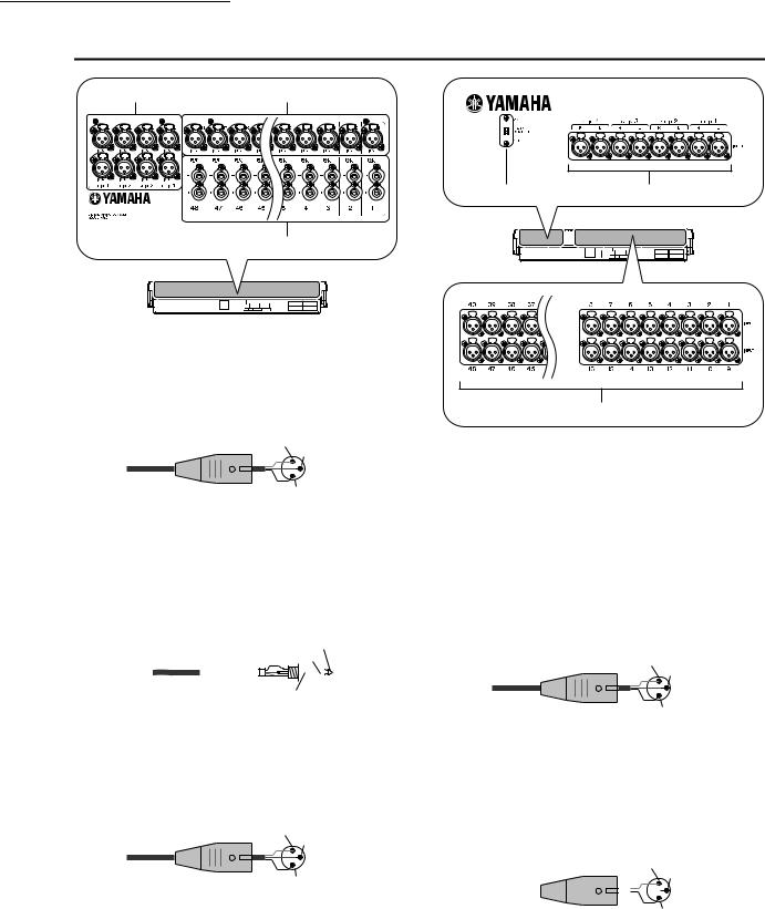
2 Top, front, and rear panels
Rear panel
3 1
2
(PM5D model)
AINPUT jacks 1–48 (PM5D model)
These are balanced XLR-3-31 type input jacks for inputting analog audio signals from line level devices or microphones. Nominal input level is
–60 dBu to +10 dBu.
Male XLR plug |
1 (ground) |
|
3 (cold) |
||
|
||
|
2 (hot) |
BINSERT IN/OUT jacks 1–48 (PM5D model only)
These are balanced TRS phone type input/output jacks for inserting external effects or dynamics processors etc. into INPUT jacks 1–48. Nominal input/output level is +4 dBu.
1/4" TRS |
|
|
|
|
Tip (hot) |
|||||||
|
Ring (cold) |
|
||||||||||
phone |
plug |
|
|
|||||||||
|
|
|
|
|
|
|
|
|
|
|||
|
|
|
|
|
|
|
|
|
|
|
|
|
|
|
|
|
|
|
|
|
|
|
|
|
|
|
|
|
|
|
|
|
|
|
|
|
|
|
Sleeve (ground)
CST IN (Stereo input) jacks 1–4 (PM5D model)
These are balanced XLR-3-31 type input jacks for inputting analog audio signals from line level devices. Nominal input level is –34 dBu to +10 dBu.
Male XLR plug |
1 (ground) |
|
3 (cold) |
||
|
||
|
2 (hot) |
4 6
(PM5D-RH model)
5
D+48V MASTER switch (PM5D-RH model only)
This is the master phantom power (+48V) switch for INPUT jacks 1–48 and ST IN jacks 1–4. If this switch is off, the +48V buttons shown in the display are unavailable.
EINPUT jacks 1–48 (PM5D-RH model)
These are balanced XLR-3-31 type input jacks for inputting analog audio signals from line level devices or microphones. Nominal input level is
–62 dBu to +10 dBu.
Male XLR plug |
1 (ground) |
|
3 (cold) |
||
|
||
|
2 (hot) |
FST IN (Stereo input) jacks 1–4 (PM5D-RH model)
These are balanced XLR-3-31 type input jacks for inputting analog audio signals from line level devices or microphones. Nominal input level is
–62 dBu to +10 dBu.
Male XLR plug |
|
1 (ground) |
||||||
|
|
|
|
3 (cold) |
||||
|
|
|
|
|
|
|
|
|
|
|
|
|
|
|
|
|
|
|
|
|
|
|
|
|
|
|
|
|
|
|
|
|
|
|
|
2 (hot)
18 |
PM5D/PM5D-RH V2 / DSP5D Owner’s Manual Operating section |
|
|
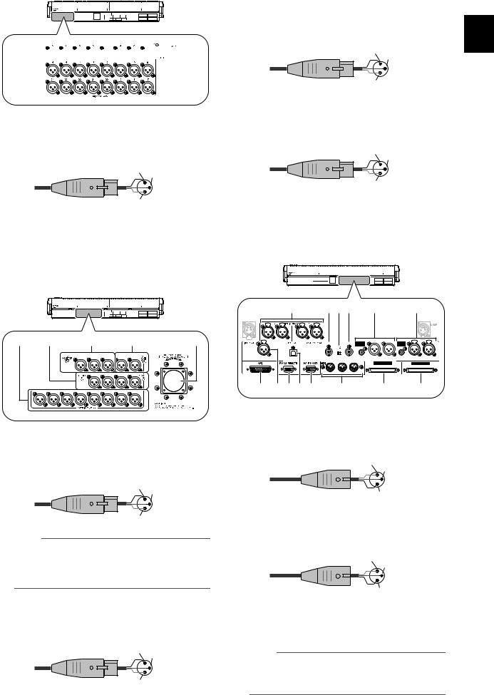
7


 8
8
GMIX OUT jacks
These are XLR-3-32 (balanced) jacks that output analog signals such as those that are patched from MIX channels 1–24. Nominal output level is +4 dBu.
Female XLR plug |
2 (hot) |
|
3 (cold) |
||
|
||
|
1 (ground) |
HLAMP connector
This is a four-pin female XLR output jack for supplying power to a gooseneck lamp. (These jacks are provided at three locations). The location of these jacks differs between the PM5D model and the PM5D-RH model.
L |
K |
|
|
9 |
|
|
J |
M |
|
|
|
C |
R |
L |
R |
L |
|
|
|
|
|
R |
L |
R |
L |
|
8 |
7 |
6 |
5 |
4 |
3 |
2 |
1 |
|
IMONITOR OUT jacks
These are XLR-3-32 (balanced) jacks that output the monitor signal selected in the MONITOR section of the top panel. Nominal output level is +4 dBu.
Female XLR plug |
2 (hot) |
|
3 (cold) |
||
|
||
|
1 (ground) |
Note
Although the various output jacks and 2TR IN ANALOG jacks have a nominal input/output level of +4 dBu (maximum level is +24 dBu), an internal switch allows this to be changed to
–2 dBu (maximum level +18 dBu) if necessary. For details, contact your Yamaha dealer.
JCUE OUT jacks
These are XLR-3-32 (balanced) jacks that output the cue monitor signal from the channel selected by its [CUE] key. Nominal output level is +4 dBu.
Female XLR plug |
2 (hot) |
|
3 (cold) |
||
|
||
|
1 (ground) |
KSTEREO OUT A/B jacks
These are XLR-3-32 (balanced) jacks that output the analog signals of the STEREO A/B channels. Nominal output level is +4 dBu.
Female XLR plug |
2 (hot) |
|
3 (cold) |
||
|
||
|
1 (ground) |
LMATRIX OUT jacks
These are XLR-3-32 (balanced) jacks that output the analog signals of MATRIX channels 1–8. Nominal output level is +4 dBu.
Female XLR plug |
2 (hot) |
|
3 (cold) |
||
|
||
|
1 (ground) |
MDC POWER INPUT connector
This is a connector for connecting the PW800W power supply. Use the dedicated cable included with the PM5D to make the connection.
|
N |
VUT |
X |
|
Y |
|
|
R |
L R |
L |
|
|
|
|
|
IN |
|
OUT |
IN |
2 |
1 |
2 |
1 |
|
75 |
|
|
|
|
|
|
|
|
|
3 |
|
3 |
|
|
|
|
ON OFF |
|
|
|
|
|
SMPTE |
USB |
|
|
COAXIAL AES/EBU |
AES/EBU |
COAXIAL AES/EBU |
AES/EBU |
|
|
THRU OUT |
IN |
|
|
|
|
Q ORPS |
W |
|
Z |
a |
|||
N2TR IN ANALOG jacks 1/2
These are XLR-3-31 (balanced) jacks that input stereo analog signals from an external source. Nominal input level is +4 dBu.
Male XLR plug |
1 (ground) |
|
3 (cold) |
||
|
||
|
2 (hot) |
OTIME CODE INPUT jack
This is an XLR-3-31 (balanced) jack that receives SMPTE time code (LTC) from an external source.
Male XLR plug |
1 (ground) |
|
3 (cold) |
||
|
||
|
2 (hot) |
PTO HOST connector
This is a USB (type B) connector that allows communication with a computer.
Note
PM5D Editor and the USB-MIDI driver required for connection with your computer can be downloaded from the Yamaha website listed below.
http://www.yamahaproaudio.com/
2
Top, front, and rear panels
PM5D/PM5D-RH V2 / DSP5D Owner’s Manual Operating section |
19 |
|
|

2 Top, front, and rear panels
QGPI connector
This is a D-sub 25-pin female connector that allows communication with a GPI-equipped external device.
RRS422 REMOTE connector
This is a D-sub 9-pin female connector for remotely controlling an external device that supports the RS422 protocol.
SHA REMOTE connector
This is a D-sub 9-pin male connector for remotely controlling an external head amp device (e.g., Yamaha AD8HR or AD824) that supports a special protocol.
TWORD CLOCK IN connector
This is a BNC connector for supplying a word clock from an external device to the PM5D.
U75Ω ON/OFF switch
This switch terminates the word clock connection. Normally you will leave this ON. If a device made by another manufacturer is connected and word clock cannot be received correctly, try turning this OFF.
VWORD CLOCK OUT connector
This is a BNC connector for supplying a word clock from the PM5D to an external device.
WMIDI IN/THRU/OUT connectors
These connectors are used to transmit and receive MIDI messages to and from external MIDI devices. The MIDI IN connector receives messages from an external device, and the MIDI OUT connector transmits messages from the PM5D. Messages received at the MIDI IN connector are retransmitted without change from the MIDI THRU connector.
X2TR OUT DIGITAL (2 track out digital) jacks 1–3
These jacks digitally output the signals of the STEREO A/B channels. Two types are provided; AES/EBU (XLR-3-32) jacks (1/2) which output AES/EBU format signals, and a COAXIAL (RCA phono) jack (3) which outputs consumer format signals (IEC60958).
Y2TR IN DIGITAL (2 track in digital) jacks 1–3
These jacks input digital audio from external devices such as CD players. Two types are provided; AES/EBU (XLR-3-31) jacks (1/2) which receive AES/EBU format
signals, and a COAXIAL (RCA phono) jack (3) which receives consumer format signals (IEC60958).
ZCASCADE OUT connector
This is a D-sub half-pitch 68-pin female connector that can be connected to another PM5D, DSP5D, DCU5D or DME64N for transmission/reception of control signals and transmission of audio signals.
aCASCADE IN connector
This is a D-sub half-pitch 68-pin female connector that can be connected to another PM5D, DSP5D or DCU5D for transmission/reception of control signals and reception of audio signals.
b c
bCooling fan vent
This is the vent for the cooling fans inside the console (two locations). When placing the unit, take care that this vent is not obstructed.
cSLOT 1–4
These slots allow separately sold mini-YGDAI I/O cards to be installed to expand the input/output ports.
Front panel
|
|
|
|
A MEMORY CARD slot |
|
|
|
|
|
A memory card inserted in this slot can be used to |
|
|
|
|
|
save/load scene memories or library data. You can use |
|
MEMORY CARD |
MOUSE |
KEYBOARD |
PHONES |
PCMCIA Type II flash ATA cards, or CompactFlash |
|
1 |
2 |
3 |
4 |
cards inserted into a PC card adaptor. |
|
B MOUSE connector |
|||||
|
|
|
|
A PS/2 mouse can be connected to this connector and used to perform operations in the display.
C KEYBOARD connector
A PS/2 keyboard can be connected to this connector and used to input text or perform operations in the display.
D PHONES (Headphone) jack
This headphone jack lets you monitor the MONITOR
OUT or CUE signals.
20 |
PM5D/PM5D-RH V2 / DSP5D Owner’s Manual Operating section |
|
|
DSP5D front panel
|
|
|
|
1 |
|
|
2 |
|
|
|
|
|
|
|
|
|
E |
|
|
|
|
|
|
|
CASCADE IN |
|
|
|
|
|
|
|
|
3 |
F |
|
OUT |
IN |
75 |
OUT |
|
IN |
|
|
|
TERMINATEDΩ |
|
|
|
||||
|
|
|
|
|
|
OUT IN |
|
|
|
|
|
|
|
|
TX RX TX RX |
|
|
4 |
5 |
|
|
|
6 |
7 |
J K |
|
OUT |
IN |
75Ω |
OUT |
IN |
TERMINATED |
||||
|
|
|
|
OUT IN |
|
|
|
|
TX RX TX RX |
8 9 L M
G
AINPUT jacks 1–48 / ST IN (stereo input) jacks 1–4
These are balanced XLR-3-31 type input jacks for inputting analog audio signals from line level devices
or microphones. The nominal input level is –62 dBu to +10 dBu. A resettable head amp is provided on all
jacks, and head amp settings can be stored in scene H memory.
B OMNI OUT jacks 1–24
These are XLR-3-32 (balanced) jacks for outputting |
I |
|||
analog audio signals. These are used mainly for output- |
||||
|
||||
ting the MIX/MATRIX/STEREO A/B channel signals. |
|
|||
The nominal output level is +4 dBu. |
|
|||
Note |
|
|
||
|
The nominal output level of OMNI OUT jacks 1–24 is +4 dBu |
J |
||
|
(maximum level is +24 dBu), but if necessary, this can be |
|||
|
|
|||
|
changed to –2 dBu (maximum level +18 dBu) by setting an |
|
||
|
internal switch (a fee will be charged). For details, please con- |
K |
||
|
tact your Yamaha dealer. |
|||
|
|
|||
|
|
|
||
C CASCADE IN/OUT connectors |
L |
|||
These are D-sub half-pitch 68-pin female connectors to allow connection of the DSP5D, PM5D, DCU5D, and
DME64N so that audio signals and control signals can M be transmitted and received.
DNETWORK connector
This connector allows the DSP5D to be connected to a Windows computer via a CAT5 Ethernet cable.
This is used mainly when remotely controlling or editing the DSP5D from the dedicated “DSP5D Editor” application software.
Note
•You should use a CAT5 STP (Shielded Twisted Pair) cable to prevent electromagnetic interference.
•DSP5D Editor and the DME-N Network driver required for connection with your computer can be downloaded from the Yamaha website listed below. http://www.yamahaproaudio.com/
WORD CLOCK IN/OUT connectors
These are BNC connectors used to input and output word clock signals from and to an external device. The input connector is terminated with 75 ohms.
CASCADE IN/OUT connectors
These are RJ-45 connectors that can be connected via a CAT5 Ethernet cable to a DSP5D or DCU5D so that audio signals and control signals can be transmitted and received.
Note
•As connectors, use RJ-45 connectors that are compatible with Neutrik’s EtherCon®.
•As cables, you should use CAT5 STP cables (shielded twisted pair cables) to prevent electromagnetic interference.
•To prevent electromagnetic interference, use conductive tape etc. to firmly fasten the metal portion of the connector to the shield of the cable.
•These connectors use EtherSound technology, but are only for use with the PM5D system; they cannot be connected to other EtherSound equipment. For details on the length of cables that can be used, refer to the following website. http://www.ethersound.com/technology/compatibility.php
IN/OUT [TX]/[RX] LED
When signals are transmitted (TX) or received (RX) via the [CASCADE IN]/[CASCADE OUT] connectors, the corresponding LED will light.
When you use the rear panel mode switch to set the machine ID, the number of LEDs corresponding to the machine ID number will light for five seconds
( p.153).
SLOT 1–2
The input/output ports can be expanded by installing separately sold mini-YGDAI I/O cards in these slots.
DC POWER INPUT connector
A separately sold PW800W power supply can be connected here as an external backup power supply. Use a power supply link cable (PSL360) to make this connection.
POWER LED
This will light if power is being supplied to the DSP5D.
POWER switch
This switch turns the power on/off.
AC IN connector
Use the included power cable to supply power to this connector.
Grounding screw
For safe operation, be sure that the DSP5D is correctly grounded. The included power cable has a three-pin plug, and if the AC outlet is grounded, the DSP5D will be grounded appropriately. If the AC outlet you’re using is not grounded, you must be sure to connect this screw to a valid electrical ground. Correct grounding will effectively eliminate noises such as hum and interference.
2
Top, front, and rear panels
PM5D/PM5D-RH V2 / DSP5D Owner’s Manual Operating section |
21 |
|
|
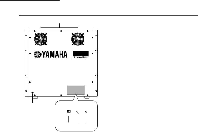
2 Top, front, and rear panels
DSP5D rear panel
1
FAN POWER
HIGH
 LOW
LOW
5
FAN POWER
HIGH 
 LOW
LOW
2 3 4
ACooling fan vents
These are the vents for the DSP5D’s internal cooling fans (two locations). When placing the unit, take care that these vents are not obstructed.
BFAN switch
This switches the rotational speed of the DSP5D’s internal cooling fans between HIGH and LOW. For normal use, set this to LOW. However if the
DSP5D is in a location of high temperature or is outside in direct sunlight, set this to HIGH. You should also set this to HIGH if you feel that the panel is warmer than usual.
CMode switch
This switch is used when initializing the settings of internal memory, when updating the firmware in the future, and when setting the machine ID number.
DPOWER LED
This will light if power is being supplied to the DSP5D.
EGrounding screw
For safe operation, be sure that the DSP5D is correctly grounded. The included power cable has a three-pin plug, and if the AC outlet is grounded, the DSP5D will be grounded appropriately. If the AC outlet you’re using is not grounded, you must be sure to connect this screw to a valid electrical ground. Correct grounding will effectively eliminate noises such as hum and interference.
22 |
PM5D/PM5D-RH V2 / DSP5D Owner’s Manual Operating section |
|
|

3 Basic operation on the PM5D
This chapter explains the various types of user interface used to operate the PM5D.
About the various types of user interface
Basic parameters such as mixing and editing the sound of each channel can be controlled by the faders and encoders of the top panel. However to make more detailed settings, you will need to access the appropriate “function” and edit the parameter values in the display. The section below explains the various user interface components shown in the display, and how to use them.
User interface in the display
The user interface in the PM5D’s display uses the following components.
Pointer
The arrow shown in the display is called the “pointer.” Use the pointer to select the parameter you want to control next.
Cursor |
Cursor |
Knobs/Faders/Boxes
Knobs/faders in the display are used to edit parameter values. The current value is shown in the box. Boxes for which  /
/  buttons are displayed at left and right allow you to edit the parameter by using these buttons. (If editing is not possible, the buttons will be gray.)
Knob
Box
Fader
Box
 /
/ buttons for editing the value
The red frame shown in the display is called |
If you want to assign a name to a channel or scene, input |
|
characters, numerals, and symbols into the box. |
||
the “cursor.” If the cursor encloses a parame- |
||
|
||
ter on the screen, that parameter is selected |
|
|
for operation. |
|
Tabs |
Tab |
|
The screen names shown in the upper left of the display are called “tabs.” Tabs are used to switch between screens within the same function.
Buttons
Buttons in the display are |
Buttons turned |
Buttons turned |
on (green) |
off (gray) |
|
used to switch parameters |
|
|
on/off or to select one of |
|
|
multiple choices. Buttons |
|
|
that are currently on are dis- |
|
|
played in green (some |
|
|
buttons are displayed in red |
|
|
or blue); buttons that are |
|
|
turned off are displayed in |
|
|
gray. |
|
|
Character palette
This is a “virtual” keyboard used to input characters, numerals, and symbols into a text input box.
3
Basic operation on the PM5D
PM5D/PM5D-RH V2 / DSP5D Owner’s Manual Operating section |
23 |
|
|

3 Basic operation on the PM5D
Scroll bar
If the displayed items are too numerous to fit into a single screen, you can use the scroll bar to view the portion that is not currently displayed.
Scroll bar
DISPLAY ACCESS section
The DISPLAY ACCESS section contains keys that access the desired function or screen in the display.
1

2

3

AGlobal functions
These keys access functions that affect the entire PM5D.
BOutput functions
These keys access functions that are related to output channels.
CInput functions
These keys access functions that are related to input channels.
When you press the key for the desired function, the screen for that function will appear in the display. By repeatedly pressing a key you can cycle through the screens included in that function.
Hint
If you hold down the [SHIFT] key and press a key in the DISPLAY ACCESS section, the screens included in that function will appear in the reverse order (Page Back function). You can also use the Page Back function by holding down a key in the DISPLAY ACCESS section. If you rapidly press a key twice, you will return to the first screen in that function.
Data Entry section
Controllers used to edit settings and values in the display are gathered into the data entry section.
7
1
2
6
3
4
5
A[DEC/CANCEL]/[INC/OK] keys
Use these keys to increase or decrease the value of the parameter where the cursor is located. If the PM5D has displayed a window asking you to confirm an operation such as recall or store, these buttons can be used instead of the CANCEL button and OK button shown in the window.
BCURSOR [√]/[®]/[π]/[†] keys
These keys are used to move the cursor to the desired parameter.
C[SHIFT] key
This key can be used in conjunction with the CURSOR [√]/[®]/[π]/[†] keys to move the cursor rapidly, or in conjunction with the [DATA] encoder or [DEC]/[INC] keys to change the parameter value rapidly.
If you hold down the [SHIFT] key and press the [ENTER] key, the JOB SELECT window will appear, allowing you to set multiple parameters in a single operation. (When you move the cursor to a parameter for which there is a JOB SELECT window, an indication of “Job Select = [SHIFT] + [ENTER]” will appear.)
D[ENTER] key
Use this key to switch a button at the cursor location on/off, or to open a window.
E[DATA] encoder
Use this to increase or decrease the value of the parameter where the cursor is located. The parameter value will change more rapidly if you turn the [DATA] encoder while holding down the [SHIFT] key.
24 |
PM5D/PM5D-RH V2 / DSP5D Owner’s Manual Operating section |
|
|
FTrack pad and left/right buttons
These are used to move the pointer or select the desired parameter. To adjust a knob-type parameter in the display, hold down the left button or right track pad button while you operate the track pad.
GPHONES (Headphone) jack
This is a stereo phone jack for connecting a set of headphones.
External user interface
If desired, you can add the following external user interface components.
Mouse
A PS/2 compatible mouse can be connected to the MOUSE connector located on the front panel of the PM5D and used in the same way as the track pad.
Keyboard
A PS/2 compatible keyboard can be connected to the KEYBOARD connector located on the front panel of the PM5D and used in the same way as the character palette in the display to input characters, numerals, and symbols. The numeric key pad of the keyboard can be used to input numerical values or to recall scenes.
Each key (or combination of keys) has the following function.
Full keyboard
Key |
Function |
|
|
|
|
||
<PageUp> |
Same function as the [INS/OK] key of the Data |
||
Entry section |
|
||
|
|
||
|
|
||
<PageDown> |
Same function as the [DEC/CANCEL] key of |
||
the Data Entry section |
|
||
|
|
||
|
|
||
<←>, <→>, |
Same function as the CURSOR [√]/[®]/[π]/ |
||
<↑>, <↓> |
[†] keys |
|
|
|
|
||
<Alt> + |
Same function as moving the [DATA] encoder |
||
<PageUp> |
clockwise |
|
|
|
|
||
<Alt> + |
Same function as moving the [DATA] encoder |
||
<PageDown> |
counterclockwise |
|
|
|
|
||
<Enter> |
Same function as the [ENTER] key |
||
|
|
||
<Shift> |
Same function as the [SHIFT] key |
||
|
|
|
|
<Ctrl> + <←>, |
Same function as the |
buttons of the |
|
<Ctrl> + <→> |
character palette |
|
|
|
|
||
<Ctrl> + <x> |
Copies the text string in the box and clears the |
||
copy-source character string (Cut) |
|||
|
|||
|
|
||
<Ctrl> + <c> |
Same function as the COPY button of the |
||
character palette |
|
||
|
|
||
|
|
||
<Ctrl> + <v> |
Same function as the PASTE button of the |
||
character palette |
|
||
|
|
||
|
|
||
<Insert> |
Same function as the INS button of the char- |
||
acter palette |
|
||
|
|
||
|
|
||
<Delete> |
Same function as the DEL button of the char- |
||
acter palette |
|
||
|
|
||
|
|
||
<Home> |
Moves the input location in the box to the |
||
beginning |
|
||
|
|
||
|
|
||
<End> |
Moves the input location in the box to after the |
||
last-input character |
|
||
|
|
||
|
|
||
<BackSpace> |
Deletes the preceding character that was |
||
input in the box (Backspace) |
|
||
|
|
||
|
|
||
<Tab> |
Switches to the next screen within the same |
||
function |
|
||
|
|
||
|
|
|
|
3
Basic operation on the PM5D
Key |
Function |
<Shift> + <Tab>
Switches to the previous screen within the same function
Accesses the function menu (if the function <Esc> menu is already displayed, recalls the last-dis-
played screen)
<Alt> +
Switch screens within the same function
<0>–<9>
Numeric key pad
Key |
Function |
|
|
|
|
<0>–<9> |
Input a scene number (if the PREFERENCE 1 |
|
screen item USE NUMERIC-KEYPAD is on), |
||
|
input numerical values (if off) |
|
|
|
|
<.> |
Returns the scene selection number to the |
|
number of the scene that was last recalled or |
||
|
stored |
|
|
|
|
<+> |
Same function as the [π] key of the SCENE |
|
MEMORY section |
||
|
||
|
|
|
<-> |
Same function as the [†] key of the SCENE |
|
MEMORY section |
||
|
||
|
|
|
</>, <*> |
Not used |
|
|
|
|
|
Same function as the [RECALL] key of the |
|
<Enter> |
SCENE MEMORY section (if the PREFER- |
|
ENCE 1 screen item USE NUMERIC-KEY- |
||
|
PAD is on), same function as the [ENTER] key |
|
|
(when off) |
|
|
|
PM5D/PM5D-RH V2 / DSP5D Owner’s Manual Operating section |
25 |
|
|
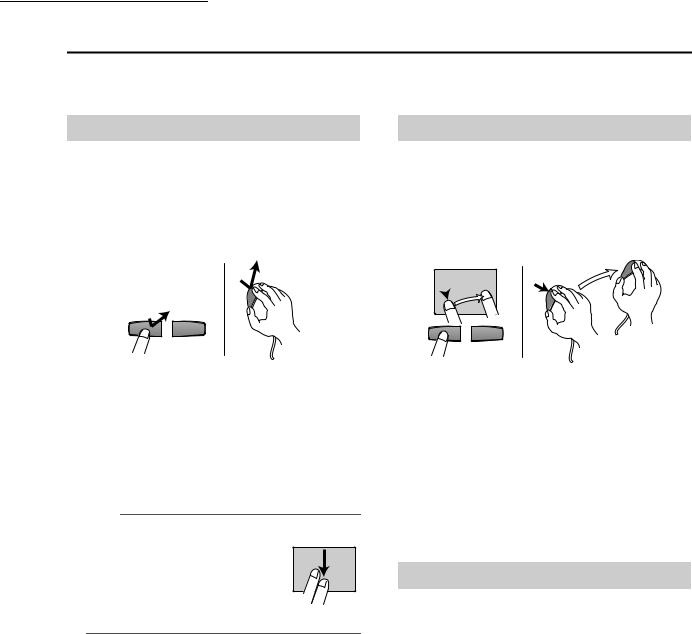
3 Basic operation on the PM5D
Basic operation
This section explains the basic procedures you can perform in the PM5D’s display. In general, you will perform operations in the PM5D’s display by combining the operations described here.
Click
Moving the pointer to a specific parameter in the screen and pressing the left/right track pad button (or the left/ right mouse button) is called “clicking.” Clicking is mainly used to turn an on-screen button on/off, to move the cursor, or to make fine adjustments to a value.
• Track pad |
• Mouse |
Click
Click
Using the CURSOR [√]/[®]/[π]/[†] keys of the data entry section to move the cursor to a desired parameter and then pressing the [ENTER] key is equivalent to clicking. If you are using a PS/2 keyboard, you can perform the same action using the arrow keys and the <Enter> key.
Subsequently in this manual, this operation will simply be called “clicking.”
Hint
When using the track pad, you can move the pointer to the desired parameter and then tap the track pad to obtain the same result as if you pressed the left button. (This is called the Tapping function.) If you want to use the tapping function, you must enable it in the PREFERENCE 2 screen (UTILITY function) ( p.206).
• Track pad
Tapping
Drag
Moving the pointer to a specific parameter in the screen and then holding down the left/right track pad (or mouse) button while moving up/down/left/right is called “dragging.” Dragging is used mainly to adjust the value of a knob or fader.
• Track pad |
• Mouse |
Drag
 Drag
Drag
While pressing
Using the CURSOR [√]/[®]/[π]/[†] keys of the data entry section to move the cursor to a desired parameter and then turning the [DATA ] encoder (or pressing the [DEC/CANCEL]/[INC/OK] keys) is equivalent to dragging. If you are using a PS/2 keyboard, you can perform the same action using the arrow keys and the <PageUp>/ <PageDown> keys (or keys that have the same function).
Subsequently in this manual, this operation will simply be called “dragging.”
Drag and drop
Moving the mouse pointer to a specific parameter in the screen, dragging to another location in the screen, and then releasing your finger is called “dragging and dropping.” Dragging and dropping is used to copy EQ or compressor settings to another channel. Dragging and dropping cannot be performed using the CURSOR keys or keyboard.
Subsequently in this manual, this operation will be called “dragging and dropping.”
26 |
PM5D/PM5D-RH V2 / DSP5D Owner’s Manual Operating section |
|
|
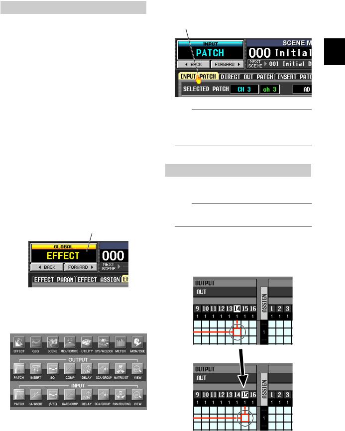
Accessing a desired screen
A desired function/screen can be accessed in the display using either of the following two methods.
Using the keys of the DISPLAY ACCESS section
1 From the keys of the DISPLAY ACCESS section, press the key corresponding to the desired function.
The most recently operated screen for that function will appear.
2 If you want to switch to another screen within that function, press the same key you pressed in step 1.
If you repeatedly press a key in the DISPLAY ACCESS section, or hold down the [SHIFT] key of the data entry section and press the same key as in step 1, you will return to the preceding screen of the same function.
Using buttons within the display
1 In any screen, click the function name area located in the upper left of the screen.
When you click the function name area, the function menu screen will appear. This screen is the starting point from which you can access the desired screen via operations in the display.
Click the function name area
2 In the function menu screen, click the button corresponding to the desired function.
The most recently operated screen for that function will appear.
3 Click a tab in the screen to select the desired screen.
Click a tab
Hint
By clicking the  buttons located below the function name area you can switch backward through the screens that had been previously displayed for at least two seconds (not including the function menu). Up to the eight most recent screens are remembered.
Moving the cursor
To select a parameter, use the data entry section’s controllers or a PS/2 keyboard to move the cursor (the red frame).
Hint
If you are using a mouse or the track pad, the cursor will move when you click on the button or knob of the desired parameter.
1 Use the CURSOR [√]/[®]/[π]/[†] keys to move the cursor.
The cursor in the display will move in the direction of the key you pressed. However, it will not move if there is no parameter in the direction of that key.
Move to the adjacent grid
3
Basic operation on the PM5D
PM5D/PM5D-RH V2 / DSP5D Owner’s Manual Operating section |
27 |
|
|

3 Basic operation on the PM5D
2 To move quickly to the outer edge of the current window or to a different window, hold down the [SHIFT] key and use the CURSOR [√]/[®]/[π]/[†] keys.
You will move from the scroll window in which the cursor is currently located, in the direction of the key you pressed.
Scrolling the screen
A scroll bar is displayed if there are more items than can be shown in a single screen. To scroll the screen, drag the box shown in the bar.
[SHIFT] key
+
CURSOR [®] key
Drag
You can also scroll the screen by clicking the vacant portion of the scroll bar or the  /
/  buttons or
  /
/  buttons located at the ends of the scroll bar.
Hint
If the cursor is located on a grid such as in a PATCH screen, turning the [DATA] encoder clockwise will move the cursor toward the right, and turning it counterclockwise will move the cursor toward the left. If you are holding down the [SHIFT] key, turning the [DATA] encoder clockwise will move the cursor downward, and turning it counterclockwise will move the cursor upward.
Click these buttons to move the |
Click in these areas to |
||
scroll bar box step-wise in the |
make the scroll bar box |
||
direction indicated. Clicking the |
move by a large step in the |
||
/ |
buttons will move in larger |
corresponding direction; |
|
steps than clicking the |
/ |
the screen will scroll |
|
buttons. |
|
|
accordingly. |
If you move the cursor to the scroll bar and press the [DEC/CANCEL] key or
turn the [DATA] encoder counterclockwise, the screen will scroll toward the left
(or upward, in the case of vertical scrolling). If you press the [INC/OK] key or
turn the [DATA] encoder clockwise, the screen will scroll toward the right (or downward, in the case of vertical scrolling).
Hint
If the cursor is located at the scroll bar box, holding down the [SHIFT] key and turning the [DATA] encoder will have the same result as clicking the  button or
  button, depending on the direction in which you turn the encoder.
28 |
PM5D/PM5D-RH V2 / DSP5D Owner’s Manual Operating section |
|
|
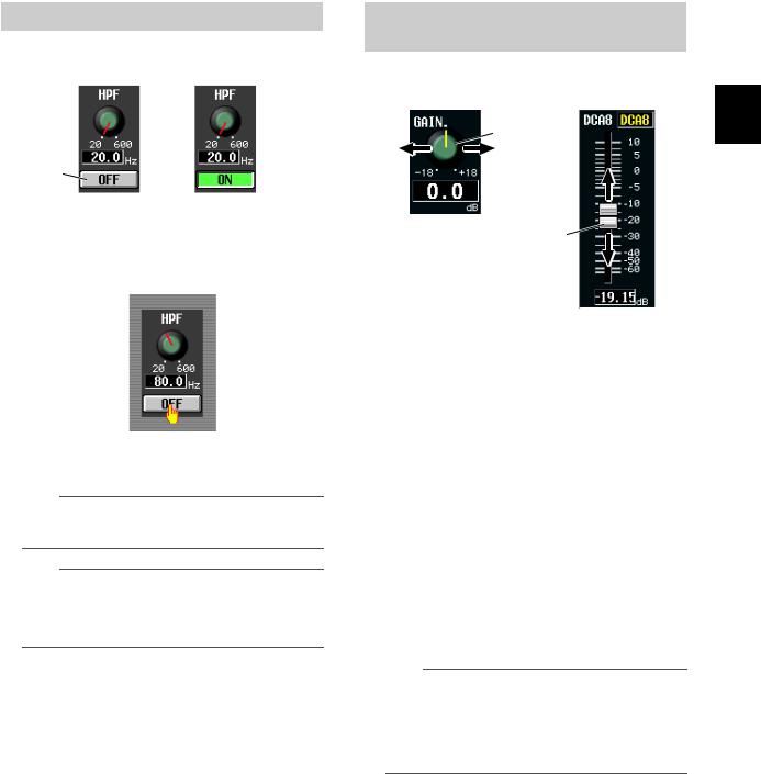
Operating the buttons
Buttons in the display are used to switch parameters on/off or to select one of multiple choices.
Click
Off On
1 Move the pointer to the desired button, and use the left/right buttons of the track pad (or mouse) to click the button.
The button will be switched on/off (or the corresponding button will be selected).
Hint
You can use the CURSOR [√]/[®]/[π]/[†] keys and the [ENTER] key (or the arrow keys and <Enter> key of a PS/2 keyboard) to perform the equivalent operation.
Hint
When using the track pad, you can also click by tapping the track pad if you have enabled tapping in the PREFERENCE 2 screen (UTILITY function p.206). In this case, the result will be the same as if you pressed the left button of the track pad (or mouse).
Adjusting the setting of a knob or fader
Knobs and faders in the display are used to adjust the value of specific parameters.
Adjust the knob value
Adjust the fader value
1 Move the pointer to the desired knob/fader, and use the left/right buttons of the track pad (or mouse) to click the knob/fader.
The cursor will move to that location.
2 To increase or decrease the value in steps of 1, click the right button or left button of the track pad (or mouse).
Clicking the right button will raise the value by one step, and clicking the left button will lower the value by one step.
3 To raise or lower the value continuously, use the track pad (or mouse) to drag the knob/ fader.
The value will change as you drag the knob or fader left/right or up/down. For a parameter whose knob has a wide range of adjustment, holding down the right button of the track pad (or mouse) as you drag will produce a larger range of change than when using the left button.
Hint
You can also adjust the value by using the [DEC/CANCEL]/ [INC/OK] keys, the [DATA] encoder, or the <PageUp>/<PageDown> keys of a PS/2 keyboard. When adjusting a parameter that has a wide range of adjustment, you can increase the rate of change by holding down the [SHIFT] key while you press the [DEC/CANCEL]/[INC/OK] keys (or turn the [DATA] encoder).
3
Basic operation on the PM5D
PM5D/PM5D-RH V2 / DSP5D Owner’s Manual Operating section |
29 |
|
|
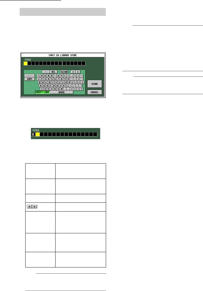
3 Basic operation on the PM5D
Assigning a name
On the PM5D you can assign a four-character name to each input channel or DCA group, and assign a title to scene and library data when saving it.
For example, the screen shown below is the LIBRARY STORE window that appears when you assign a name to the INPUT EQ library. To input characters in this screen, use the following procedure.
1 Use the character palette (or a PS/2 keyboard) to input a character.
When you click the character palette, a character will be input in the box, and the highlighted area will move to the right.
2 Input the subsequent characters in the same way.
When inputting characters, you can use the following buttons in the character palette.
Inserts a space (blank) at the high-
INS button
lighted position. Pressing the <Insert> key of a PS/2 keyboard will produce the same result.
Deletes the character at the high-
DEL button
lighted position. Pressing the <Delete> key of a PS/2 keyboard will produce the same result.
CLEAR button
Deletes all characters that have been input in the text input box.
buttons
Move the highlighted area to left or right.
Pastes the character string that was copied to buffer memory by the
PASTE button
COPY button. Holding down the <Ctrl> key and pressing the <V> key of a PS/2 keyboard will produce the same result.
Copies the character string in the box to a temporary buffer memory. Hold- COPY button ing down the <Ctrl> key and pressing
the <C> key of a PS/2 keyboard will produce the same result.
Switches between uppercase and
CAPS LOCK button
lowercase alphabetical characters. Uppercase characters can be input while this button is on.
Note
Copy/paste operations are not possible in some screens. There are also cases in which the paste operation cannot be performed due to the type of character string copied to the buffer memory.
3 When you have finished inputting the name, click the STORE button.
The name you input will be stored.
Hint
•In general, the same procedure applies in screens where you enter names for scenes or other library items.
•If a PS/2 keyboard is connected, you can use it to enter characters.
•If you move the cursor to the text input box and press the [ENTER] key (or click), the input position will move to that point. If the cursor is located at the text input box, you can step through the available characters by turning the [DATA] encoder. If the cursor is located elsewhere, turning the [DATA] encoder will move the selected position. The [INC]/ [DEC] keys move the selected position regardless of where the cursor is located.
Note
The number of characters that can be input will depend on the type of data (scene/library) you are saving. You cannot input more than the specified number of characters, or move the highlighted area beyond that range.
30 |
PM5D/PM5D-RH V2 / DSP5D Owner’s Manual Operating section |
|
|
 Loading...