


50/144/430 MHz
TRIPLE-BAND HEAVY DUTY SUBMERSIBLE TRANSCEIVER
VX-8DR
OPERATING MANUAL
VERTEX STANDARD CO., LTD.
4-8-8 Nakameguro, Meguro-Ku, Tokyo 153-8644, Japan
VERTEX STANDARD
US Headquarters
10900 Walker Street, Cypress, CA 90630, U.S.A.
YAESU UK LTD.
Unit 12, Sun Valley Business Park, Winnall Close
Winchester, Hampshire, SO23 0LB, U.K.
VERTEX STANDARD HK LTD.
Unit 5, 20/F., Seaview Centre, 139-141 Hoi Bun Road,
Kwun Tong, Kowloon, Hong Kong
VERTEX STANDARD (AUSTRALIA) PTY., LTD.
Normanby Business Park, Unit 14/45 Normanby Road Notting Hill 3168, Victoria, Australia

Contents
Introduction ................................................................................. |
1 |
Controls &Connections ............................................................... |
2 |
Display Icons & Indicators ......................................................... |
3 |
Keypad Functions ....................................................................... |
4 |
Accessories & Option .................................................................. |
6 |
Accessories Supplied with the VX-8R ..................................... |
6 |
Available Options for your VX-8R .......................................... |
7 |
Installation of Accessories ........................................................... |
8 |
Antenna Installation ................................................................. |
8 |
Belt Clip Installation ................................................................ |
8 |
Installation of FNB-101LI Battery Pack .................................. |
9 |
Battery Life Information ........................................................ |
10 |
Installation of FBA-39 Alkaline Battery Case ....................... |
11 |
Interface of Packet TNCs .......................................................... |
12 |
Operation ................................................................................... |
13 |
Switching Power On and Off ................................................. |
13 |
Adjusting the Volume Level .................................................. |
13 |
Squelch Adjustment ............................................................... |
14 |
Selecting the Operating Band ................................................ |
15 |
Selecting the Frequency Band ................................................ |
16 |
Frequency Navigation ............................................................ |
17 |
1) Tuning Dial .................................................................. |
17 |
2) Direct Keypad Frequency Entry .................................. |
17 |
3) Scanning ....................................................................... |
18 |
Transmission .......................................................................... |
19 |
Changing the Transmitter Power Level ............................ |
19 |
VOX Operation ................................................................ |
20 |
AM and FM Broadcast Reception ......................................... |
22 |
AF-Dual Operation ........................................................... |
24 |
Advanced Operation ................................................................. |
26 |
Keyboard Locking ................................................................. |
26 |
Adjusting the Keypad Beeper Volume Level ......................... |
27 |
Setting the Frequency Display Image Size ............................. |
27 |
Audio Muting ......................................................................... |
28 |
Keypad/LCD Illumination ...................................................... |
28 |
Changing the Channel Steps .................................................. |
29 |
Changing the Receiving Mode ............................................... |
29 |
SQL S-meter .......................................................................... |
30 |
Repeater Operation ................................................................... |
31 |
General ................................................................................... |
31 |
Repeater Shifts ....................................................................... |
31 |
Automatic Repeater Shift (ARS) ........................................... |
31 |
Manual Repeater Shift Activation .......................................... |
32 |
Changing the Default Repeater Shifts .............................. |
32 |
Checking the Repeater Uplink (Input) Frequency ................. |
33 |
CTCSS/DCS/EPCS Operation ................................................. |
34 |
CTCSS Operation .................................................................. |
34 |
DCS Operation ...................................................................... |
36 |
DCS Code Inversion ........................................................ |
37 |
Tone Search Scanning ........................................................... |
39 |
EPCS (Enhanced Paging & Code Squelch) ........................... |
40 |
Storing the CTCSS Tone Pairs for EPCS Operation ....... |
40 |
Activating the Enhanced Paging & Code Squelch System .. |
41 |
Paging Answer Back ........................................................ |
41 |
CTCSS/DCS/EPCS Bell Operation ....................................... |
42 |
Programming the User Melody ........................................ |
43 |
Split Tone Operation .............................................................. |
44 |
Tone Calling (1750 Hz) ......................................................... |
45 |
Memory Mode (Regular Memory Channel Operation) ......... |
46 |
Memory Storage .................................................................... |
47 |
Memory Recall ....................................................................... |
48 |
HOME Channel Memory ....................................................... |
49 |
Labeling Memories ................................................................ |
50 |
Memory Offset Tuning .......................................................... |
51 |
Masking Memories ................................................................ |
52 |
Memory Bank Operation ....................................................... |
53 |
Moving Memory Data to the VFO ........................................ |
55 |
Memory Only Mode ............................................................... |
55 |
Memory Mode (Special Memory Channel Operation) .......... |
56 |
Weather Broadcast Channels ................................................. |
56 |
VHF Marine Memory Channels ............................................. |
57 |
Short-wave Broadcast Station Memory Channels ................. |
58 |
Scanning ..................................................................................... |
60 |
General ................................................................................... |
60 |
VFO Scanning ........................................................................ |
62 |
How to Skip (Omit) a Frequency during VFO Scan ........ |
63 |
Memory Scanning .................................................................. |
64 |
How to Skip (Omit) a Channel during Memory Scan ...... |
65 |
Preferential Memory Scan ................................................ |
66 |
Memory Bank Scan .......................................................... |
67 |
Programmable (Band Limit) Memory Scan (PMS) ............... |
68 |
“Priority Channel” Scanning (Dual Watch) ........................... |
69 |
Priority Revert Mode ....................................................... |
70 |
Automatic Lamp Illumination on Scan Stop .......................... |
71 |
Band Edge Beeper ................................................................. |
71 |
Bluetooth® Operation ............................................................. |
72 |
Pairing .................................................................................... |
72 |
Activation ............................................................................... |
73 |
Operation ............................................................................... |
74 |
GPS Operation .......................................................................... |
76 |
Setting the Time Zone (Time Offset) ..................................... |
78 |
Selecting the Display Units of the GPS Screen ...................... |
79 |
Selecting the Map Datum ...................................................... |
79 |
APRS® Operation ...................................................................... |
80 |
Preparations ........................................................................... |
80 |
Receiving an APRS Beacon ................................................... |
83 |
Transmit an APRS Beacon .................................................... |
85 |
Receiving an APRS Message ................................................. |
88 |
Transmit an APRS Message .................................................. |
90 |
ARTSTM (Automatic Range Transponder System) ................ |
92 |
Basic ARTSTM Setup and Operation ..................................... |
93 |
ARTSTM Polling Time Options .............................................. |
93 |
ARTSTM Alert Beep Options ................................................. |
94 |
CW Identifier Setup ............................................................... |
95 |
Spectrum Analyzer Operation ................................................. |
96 |
Channel Counter Operation ..................................................... |
98 |
Smart Search Operation ......................................................... |
100 |
Message Feature ...................................................................... |
102 |
General ................................................................................. |
102 |
Programming a Message ...................................................... |
102 |
Programming a Member List ............................................... |
103 |
Set your Personal ID ............................................................ |
104 |
Sending a Message ............................................................... |
105 |
Receiving a Message ............................................................ |
106 |
Emergency Feature ................................................................. |
107 |
Emergency Channel Operation ............................................ |
107 |
Emergency Automatic ID (EAI) feature .............................. |
108 |
Selecting the EAI mode and its Transmit Time .............. |
109 |
Activating the EAI feature ............................................. |
109 |
To Locate an Unresponsive Operator |
|
using the EAI feature .......... |
110 |
Internet Connection Feature .................................................. |
111 |
General ................................................................................. |
111 |
SRG (“Sister Radio Group”) Mode ..................................... |
111 |
FRG (“Friendly Radio Group”) Mode ................................. |
112 |
DTMF Operation ..................................................................... |
114 |
CW Learning Feature ............................................................. |
116 |
CW Training Feature .............................................................. |
118 |
Sensor Mode ............................................................................. |
119 |
Sensor Mode Options .......................................................... |
120 |
Clock Set ........................................................................ |
120 |
Selecting the Measurement Units of the Sensor Unit ..... |
121 |
Correcting the Sensor Unit ............................................. |
121 |
Miscellaneous Setting .............................................................. |
122 |
Password .............................................................................. |
122 |
Programming the [Internet(TXPO)] Key ............................. |
123 |
ATT (Front End Attenuator) ............................................... |
124 |
Receive Battery Saver Setup ............................................... |
125 |
TX Battery Saver ................................................................. |
125 |
Disabling the BUSY Indicator ............................................. |
126 |
Automatic Power-Off (APO Feature) .................................. |
126 |
Transmitter Time-Out Timer (TOT) .................................... |
127 |
ON/OFF Preset Timer .......................................................... |
128 |
Busy Channel Lock-Out (BCLO) ........................................ |
129 |
Changing the TX Deviation Level ....................................... |
129 |
Changing the Microphone Gain ........................................... |
130 |
S-and TX Power Meter Symbols ......................................... |
130 |
Display Contrast .................................................................. |
131 |
Display Dimmer ................................................................... |
131 |
My Bands Operation ............................................................ |
132 |
Changing the Status of the [VOL] Key ................................ |
133 |
Reset Procedures ..................................................................... |
134 |
Cloning ..................................................................................... |
135 |
Set Mode ................................................................................... |
136 |
APRS/GPS Set Mode .............................................................. |
162 |
Specifications ........................................................................... |
168 |
Installation of the BU-1 (Option) ........................................... |
170 |

INTRODUCTION
The Ultra Compact VX-8DR (2.4”W x 3.7”H x 0.9”D) is thinner than the previous advanced model - It is packed with advanced technology and features, designed for outdoor operation. It is submersible and shockproof! The compact case combines a rugged die-cast chassis with the clean, tough polycarbonate resin front panel. Its shockproof versatility will allow you to operate the radio in the toughest environments.
The large High-resolution Dot Matrix LCD display provides clear, easy-to-read indication of both “A” (Main band) and “B” (Sub band) frequencies, the operating mode, and S-meters for both bands. When you engage the Spectrum Scope function, the high-resolution display will indicate relative signal strengths of up to ±50 adjacent channels!
The Bluetooth® capabilities, already known and utilized among users and enthusiasts of the FTM-10R/SR, are also available with the VX-8DR. The optional Bluetooth® Unit BU-1 makes it possible to operate Hands-free with the optional waterproof Bluetooth® headsets BH-1A (Stereo) or BH-2A (monaural).
The built-in worldwide standard AX.25 Data TNC Modem permits uncomplicated APRS® operation. (Automatic Packet/Position Reporting System: APRS® is a registered trademark of the APRS Software and Bob Bruninga, WB4APR.) The VX-8DR supports APRS® 1200/9600 bps data communication on the B band only. You may communicate your location to other APRS® stations along with the position, speed and heading displayed on your radio! You and others will be able to see your APRS® movement on the web! The VX-8DR displays the received station’s positions, heading directions, messages, distances, icons (43 kinds), weather information, object, etc. With the list function you may automatically store and recall up to 20 messages and the APRS® data from up to 40 stations. The optional GPS Antenna Unit FGPS- 2 can provide you with your real time APRS® data. You may also send the information without the FGPS-2 if you manually input your data in advance.
An Enhanced Paging and Code Squelch (EPCS) allows you to page a particular station and only receive calls from that station. A security Password may be set, which will allow you to turn on and operate the transceiver only after you enter the Password. A convenient key provides access to Vertex Standard's WIRES™ (Wide-Coverage Internet Repeater Enhancement System). The Emergency Automatic ID (EAI) function can automatically cause your VX-8DR to transmit your callsign and engage your rig’s microphone, even if you are disabled and unable to press the PTT switch. Additional features include: transmit Time-Out Timer (TOT), Automatic Power-Off (APO), and Automatic Repeater Shift (ARS). Yaesu’s exclusive ARTS™ (Auto-Range Transponder System) which “beeps” the user when you move out of communications range with another ARTS™ equipped station. There is provision to reduce the TX deviation for use in areas of high channel congestion. The squelch circuit allows adjusting the squelch to open at a programmable setting of the S-Meter, thus reducing guesswork in setting the squelch threshold. Provides a completely independent FM/AM broadcast receiver and an internal bar antenna for better AM broadcast reception. Listen to FM broadcasts in stereo with your stereo headset/earphone!
We appreciate your purchase of the VX-8DR, and encourage you to read this manual thoroughly, and learn about the many exciting features of your thrilling new Yaesu hand-held transceiver!
VX-8DR OPERATING MANUAL |
1 |

CONTROLS & CONNECTIONS
ANTENNA Jack Connect the supplied rubber flex antenna (or another antenna presenting a 50-Ohm impedance) here.
PTT Switch
(“Push To Talk”) Press this switch inward to transmit, and release it (to receive) after your transmission is completed.
MONI Key Pressing this key disables the noise squelching action, allowing you to hear very weak signals near the background noise level.
VOL Key
Rotate the DIAL knob while pressing and holding this key to adjust the audio volume level.
F/W Key Pressing this key activates the “Alternate” key function of the keypad.
SPEAKER
T h e i n t e r n a l speaker is located hear.
MIC/SP Jack This 7-pin miniature jack connects an optional MH74A7A Speaker Microphone or CT136 GPS Antenna Adapter.
KEYPAD
The 20 front panel key buttons select many of the most important operating features.
The functions of the keys are described in details on pages 4 and 5.
DIAL Knob The main tuning Dial is used to set the operating frequency, and is also used for audio volume level, menu selections, and other adjustments.
MIC
The internal microphone is located hear.
LED Light This white LED will glow (or flash) during “Emergency Channel” operation. It can also be useful as a flash light in a dark environment via the Set Mode Item 50 LED LIGHT.
EAR Jack This 3-contact miniature jack allows connection of stereo earphones . With aftermarket earphones, you may enjoy stereo FM broadcasts.
EXT DC
This coaxial DC jack allows connection to an external DC power source (4-14V DC). The center pin of this jack is the Positive
(+) line.

 (PWR) Switch
Press and hold this switch for 2 seconds to toggle the transceiver’s power “on” and “off”.
Press this switch briefly while the t r a n s c e i v e r i s turned “on” to toggle the key lockout feature “on” or “off”.
Some stereo earphone plugs may not fit this jack, depending on the shape of the connection plug.
2 |
VX-8DR OPERATING MANUAL |
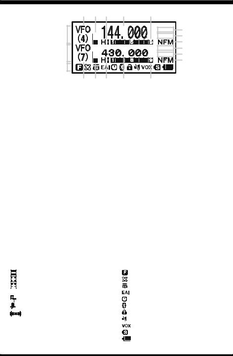
DISPLAY ICONS & INDICATORS
“B” Band
Display
Icon
|
|
|
|
|
|
|
|
|
|
|
|
|
|
|
|
|
|
|
|
|
|
|
|
FREQUENCY CONTROL |
VOLUME LEVEL |
||||
VFO: VFO Mode |
TX POWER LEVEL |
||||
MR: |
Memory Mode |
||||
|
|||||
MT: Memory Tune Mode |
HI: High Power (5 W) |
||||
|
|||||
HOM: Home Channel Memory |
L3: LOW3 Power (2.5 W) |
||||
|
|||||
PMS: Programmable Memory Scan Mode |
L2: LOW2 Power (1 W) |
||||
|
|||||
VDW: Dual Watch Active |
L1: LOW1 Power (0.02 W) |
||||
|
|||||
|
|
|
(VFO-Memory Channel) |
OPERATING FREQUENCY |
|
MDW:Dual Watch Active |
|||||
|
|||||
|
|
|
(Memory Channel-Memory Channel) |
S&PO METER |
|
SQUELCH TYPE & RADIO MODE |
|
||||
TN: |
Tone Encoder Active |
|
|||
TSQ: |
Tone Squelch Active |
|
|||
DCS: |
Digital Code Squelch Active |
|
|||
RTN: |
Reverse Tone Squelch Active |
|
|||
PR: |
User Programmed Reverse CTCSS Decoder Active |
||||
PAG: |
Enhanced Paging & Code Squelch (EPCS) Active |
||||
MSG: |
Message Feature Active |
|
|||
DC: |
Split Tone Feature Active (DCS Encode only) |
||||
T-D: |
Split Tone Feature Active (Encodes a CTCSS Tone and Decodes a DCS Code) |
||||
D-T: |
Split Tone Feature Active (Encodes a DCS Code and Decodes a CTCSS Tone) |
||||
A12: |
APRS® Feature Active (1200 bps) |
|
|||
A96: |
APRS® Feature Active (9600 bps) |
|
|||
|
|
|
: AM/FM Broadcast Reception |
|
|
|
|
|
|
||
MISCELLANEOUS SETTING |
ICON |
||
: |
Repeater Shift Direction (Minus Shift) |
: |
Secondary Keypad Active |
: |
Repeater Shift Direction (Plus Shift) |
: |
Internet Connection Feature (WiRESTM) Active |
: |
Independent Transmit Frequencies |
: |
DTMF Autodialer Active |
|
(Odd Splits) |
: |
Emergency Automatic ID (EAI) Feature Active |
: |
Attenuator Active |
: |
Automatic Power-Off Active |
: |
Bell Alarm Active |
: |
Bluetooth® Active |
|
: Receiving an FM Stereo Signal |
: |
Key Lock Active |
OPERATING MODE |
: |
Mute Feature Active |
|
|
: VOX Feature Active |
||
NFM: FM |
: |
Battery Saver Active |
|
WFM: Wide FM |
|
: Battery Indicator |
|
AM: AM |
|
|
|
VX-8DR OPERATING MANUAL |
3 |

KEYPAD FUNCTIONS
|
|
|
|
|
|
|
|
|
|
|
|
|
|
|
|
|
|
|
|
|
|
|
|
|
|
|
|
|
|
|
|
Switches the “Upper” |
Switches the “Lower” |
Increases the VFO |
|||||
PRIMARY FUNCTION |
frequency by one step or |
||||||||
frequency to be the |
frequency to be the |
||||||||
(PRESS KEY) |
|
moves the memory channel |
|||||||
|
“Operating” (TX) Band. |
“Operating” (TX) Band. |
|||||||
|
|
to the next-highest channel. |
|||||||
|
|
|
|
|
|
|
|
||
SECONDARY FUNCTION |
No Action |
No Action |
Tunes the VFO frequency |
||||||
(PRESS + |
) |
upward in 1 MHz steps. |
|||||||
|
|
|
|
|
|
||||
|
|
|
|
|
|
|
|
|
|
THIRD FUNCTION |
|
|
|
|
|
|
Activates the Scanner |
||
Activates the |
Activates the |
Upward (toward a higher |
|||||||
(PRESS AND HOLD KEY) |
Dual Receive Feature. |
Dual Receive Feature. |
frequency or a higher |
||||||
|
|
|
|
|
|
|
|
channel number). |
|
|
|
|
|
|
|
|
|
|
|
|
|
(1) Moves operation to the |
|
|
|
|
|||
PRIMARY FUNCTION |
next-highest frequency band. |
Frequency entry digit “1” |
Frequency entry digit “2” |
||||||
(PRESS KEY) |
|
(2) Activates the Memory Bank |
|||||||
|
|
|
|
|
|||||
|
|
feature. |
|
|
|
|
|||
SECONDARY FUNCTION |
Moves operation to the |
Selects the synthesizer steps |
Selects the CTCSS Tone, |
||||||
(PRESS + |
) |
next-lowest frequency band |
to be used during VFO |
DCS code, EPCS code, or |
|||||
operation. |
Message. |
||||||||
|
|
|
|
|
|||||
|
|
|
|
|
|
|
|
|
|
|
|
(1) Select the Bandwidth for |
|
|
|
|
|||
THIRD FUNCTION |
the VFO scanner. |
No Action |
No Action |
||||||
(PRESS AND HOLD KEY) |
(2) Select the Memory Scan |
||||||||
|
|
|
|
||||||
|
|
mode. |
|
|
|
|
|||
|
|
|
|
|
|
|
|
|
|
PRIMARY FUNCTION |
Reverses transmit and |
|
|
|
|
||||
receive frequencies while |
Frequency entry digit “4” |
Frequency entry digit “5” |
|||||||
(PRESS KEY) |
|
||||||||
|
working through a repeater. |
|
|
|
|
||||
|
|
|
|
|
|
||||
|
|
|
|
|
|
|
|
|
|
SECONDARY FUNCTION |
Switches operation to the |
Activates the ARTS feature. |
Activates the Memory Scan |
||||||
“Home” (favorite frequency) |
“Skip” channel selection |
||||||||
(PRESS + |
) |
||||||||
|
|
|
|||||||
channel. |
|
|
|
mode. |
|||||
|
|
|
|
|
|||||
|
|
|
|
|
|
|
|
||
THIRD FUNCTION |
Activates the EMERGENCY |
No Action |
No Action |
||||||
(PRESS AND HOLD KEY) |
function. |
||||||||
|
|
|
|
||||||
|
|
|
|
|
|
|
|
|
|
|
|
|
|
|
|
|
|
|
|
PRIMARY FUNCTION |
Activates the Internet |
Frequency entry digit “7” |
Frequency entry digit “8” |
||||||
(PRESS KEY) |
|
Connection feature. |
|||||||
|
|
|
|
|
|||||
|
|
|
|
|
|
|
|
|
|
SECONDARY FUNCTION |
Selects the desired transmit |
Activates the AF Dual |
Activates the Spectrum |
||||||
function while receiving the |
Analyzer (Spectra-ScopeTM) |
||||||||
(PRESS + |
) |
power output level. |
Broadcast Stations. |
feature. |
|||||
|
|
|
|
|
|||||
|
|
|
|
|
|
|
|
||
THIRD FUNCTION |
No Action. |
No Action |
No Action |
||||||
(PRESS AND HOLD KEY) |
|||||||||
|
|
|
|
|
|
|
|||
|
|
|
|
|
|
|
|
|
|
|
|
|
|
|
|
|
|
|
|
4 |
VX-8DR OPERATING MANUAL |

KEYPAD FUNCTIONS
|
|
|
|
|
|
|
|
Decreases the VFO |
Activate the APRS (Automatic |
PRIMARY FUNCTION |
USA Version: Disables the Noise |
||||
frequency by one step or |
and Tone Squelch System. |
||||||
moves the memory channel |
Position Reporting System) |
(PRESS KEY) |
|
EXP Version: Activates the T.CALL |
|||
function. |
|
||||||
to the next-lowest channel. |
|
|
(1750 Hz) for repeater access. |
||||
|
|
|
|||||
Tunes the VFO frequency |
No Action |
SECONDARY FUNCTION |
Adjusts the Squelch |
||||
downward in 1 MHz steps. |
(PRESS + |
) |
threshold level. |
|
|||
|
|
||||||
|
|
|
|
|
|||
Activates the Scanner |
|
THIRD FUNCTION |
USA Version: Disables the Noise |
||||
Downward (toward a lower |
Enter the Set Mode. |
and Tone Squelch System. |
|||||
frequency or a lower channel |
(PRESS AND HOLD KEY) |
EXP Version: Activates the T.CALL |
|||||
|
|||||||
number). |
|
|
|
(1750 Hz) for repeater access. |
|||
|
|
|
|
|
|
|
|
|
Selects the receive mode |
PRIMARY FUNCTION |
|
|
|
||
Frequency entry digit “3” |
among AM, FM, |
No Action |
|
||||
(PRESS KEY) |
|
|
|||||
|
and Wide FM. |
|
|
|
|
||
|
|
|
|
|
|
||
|
|
|
|
|
|||
|
|
SECONDARY FUNCTION |
Toggle the DIAL knob |
||||
Selects the DTMF mode. |
Activates the CTCSS |
function between the |
|||||
or DCS operation. |
(PRESS + |
) |
“Frequency Control” and |
||||
|
|||||||
|
|
|
|
“Receiver Audio Control”. |
|||
|
Engage the Special |
THIRD FUNCTION |
Rotate the DIAL knob while |
||||
No Action |
holding this key to adjust the |
||||||
(PRESS AND HOLD KEY) |
|||||||
Search mode. |
|||||||
|
audio volume level. |
||||||
|
|
|
|
||||
|
|
|
|
|
|
|
|
|
|
|
|
|
|
|
|
|
Switches frequency control |
PRIMARY FUNCTION |
Activates the “Secondary” |
||||
Frequency entry digit “6” |
between the VFO and |
||||||
|
|
||||||
(PRESS KEY) |
|
key function. |
|
||||
|
Memory System. |
|
|
||||
|
|
|
|
|
|
||
|
|
|
|
|
|
|
|
Selects the direction of the |
Activates the “Memory Tune” |
|
|
|
|
|
|
uplink frequency shift (either |
SECONDARY FUNCTION |
Disables the “Secondary” |
|||||
mode while in the Memory |
|||||||
“–”, “+”, or “simplex”) during |
(PRESS + |
) |
key function. |
|
|||
Recall mode. |
|
||||||
repeater operation. |
|
|
|
|
|
||
|
|
|
|
|
|
||
No Action |
Activates the Priority (Dual |
THIRD FUNCTION |
Activates the “Memory Write” |
||||
Watch) function. |
(PRESS AND HOLD KEY) |
mode (for memory channel |
|||||
|
|||||||
|
storage). |
|
|||||
|
|
|
|
|
|||
|
|
|
|
|
|
||
|
|
|
|
NOTE |
|
||
|
|
|
|
1: The |
and |
keys |
|
|
|
|
|
||||
Frequency entry digit “9” |
Frequency entry digit “0” |
PRIMARY FUNCTION |
glows green when the |
||||
(PRESS KEY) |
|
squelch |
opens, |
and |
|||
|
|
|
turns red during trans- |
||||
|
|
|
|
||||
|
|
|
|
mission. |
|
|
|
|
|
|
|
|
|
||
Enters the “Special Memory” |
Enters the Broadcast |
SECONDARY FUNCTION |
2: P r e s s t h e |
o r |
|||
key to switch the |
|||||||
mode. |
Reception mode. |
(PRESS + |
) |
||||
frequency display be- |
|||||||
|
|
|
|
||||
|
|
|
|
tween the “Double-size |
|||
|
|
|
|
||||
|
|
THIRD FUNCTION |
Character” and “Small |
||||
No Action |
No Action |
Character” mode while |
|||||
(PRESS AND HOLD KEY) |
|||||||
|
|
Mono band operation. |
|||||
|
|
|
|
||||
|
|
|
|
|
|
|
|
|
|
|
|
|
|
|
|
VX-8DR OPERATING MANUAL |
|
|
|
|
5 |
||

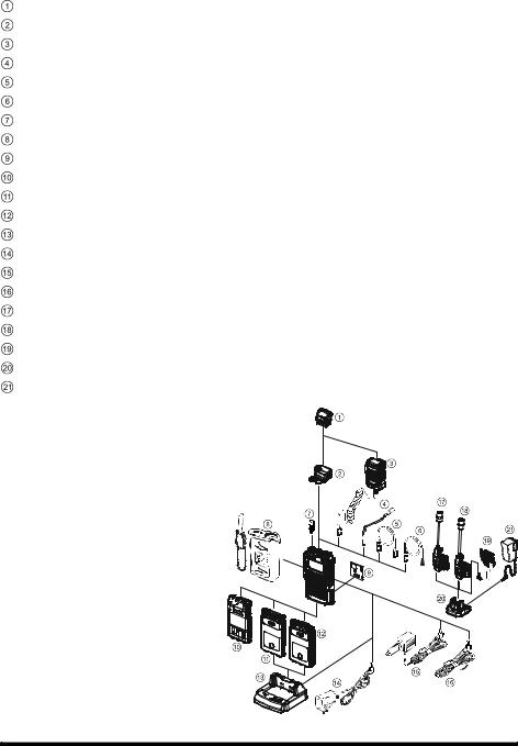
ACCESSORIES & OPTIONS
ACCESSORIES SUPPLIED WITH THE VX-8DR
Antenna |
1 pc |
YHA-65 (for USA version: Q3000185) or |
|
|
YHA-64 (for EXP version: Q3000183) |
Li-Ion Battery Pack |
1 pc |
FNB-101LI (7.4V/1,100mAh: AAG10X001) |
Battery Charger |
1 pc |
NC-86B (for USA version: Q9500149) or |
|
|
NC-86C (for EXP version: Q9500150) |
Connector Unit |
1 pc |
(CB4392001) |
Belt Clip |
1 pc |
(RA1053600) |
Screws |
2 pcs |
(M3x10SUS: U24310020) |
Plastic Cap |
1 pc |
(RA1054200) |
Sheet |
2 pcs |
(RA1066900) |
Operating Manual |
1 pc |
|
Warranty Card |
1 pc |
|
6 |
VX-8DR OPERATING MANUAL |
|
ACCESSORIES & OPTIONS |
|
|
|
|
|
|
|
|
AVAILABLE OPTIONS FOR YOUR VX-8DR |
|
|
|
FGPS-2 |
GPS Antenna Unit |
CT-136 |
GPS Antenna Adapter |
MH-74A7A |
Waterproof Speaker/Microphone |
CT-131 |
Microphone Adapter |
CT-134 |
Clone Cable |
CT-M11 |
MIC/SP Connection Cable |
CN-3 |
BNC-to-SMA Adapter |
CSC-93 |
Soft Case |
BU-1 |
Bluetooth® Unit |
FBA-39 |
3 x “AA” Cell Battery Case (batteries not supplied) |
FNB-101LI |
Li-Ion Battery Pack (7.4V/1,100 mAh) |
FNB-102LI |
Li-Ion Battery Pack (7.4V/1,800 mAh) |
CD-41 |
Rapid Charger (requires NC-86B/C/U) |
NC-86B/C/U |
Battery Charger for the CD-41 |
E-DC-5B |
DC Cable w/Noise Filter |
E-DC-6 |
DC Cable; plug and wire only |
BH-2A |
Bluetooth® Headset (Monaural) |
BH-1A |
Bluetooth® Headset (Stereo) |
FEP-4 |
Earphone for BH-1A |
CD-40 |
Charger Cradle for the BH-1A/BH-2A (requires NC-85B/C/U) |
NC-85B/C/U |
Battery Charger for the CD-40 |
: “B” suffix is for use with 120 VAC (Type-A plug), “C” suffix is for use with 230 VAC (Type- C plug), and “U” suffix is for use with 230 VAC (Type-BF plug).
Availability of accessories may vary.
Some accessories are supplied as stan-
dard per local requirements, while others may be unavailable in some regions. Consult your Yaesu Dealer for details regarding these and any newly-
available options. Connection of any  non-Yaesu approved accessory, should
it cause damage, may void the Limited Warranty on this apparatus.
VX-8DR OPERATING MANUAL |
7 |
INSTALLATION OF ACCESSORIES
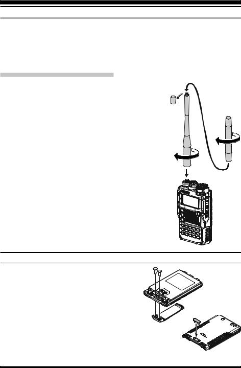
ANTENNA INSTALLATION
The supplied antenna provides good results over the entire frequency range of the transceiver. However, for enhanced base station medium-wave and shortwave reception, you may wish to connect an external (outside) antenna. The supplied antenna consists of two sections: the “Base Antenna” (used for operation above 50 MHz), and the “Extender Element” (used for monitoring of frequencies below 50 MHz).
TO INSTALL THE SUPPLIED ANTENNA
Hold the bottom end of the antenna, then screw it onto the mating connector on the transceiver until it is snug. Do not over-tighten by use of extreme force.
When operating the VX-8DR on the 50 MHz band and lower frequencies, disconnect the antenna cap from the base antenna, then screw the Extender Element onto the Antenna Base. Of course, the VX-8DR may be operated on frequencies higher than the 50 MHz band while the Extender Element is still attached to the Antenna Base.
Notes:
Never transmit without having an antenna connected.Carefully turn the supplied antenna onto the SMA jack.
Never twist the upper part of the antenna while screwing it onto the mating connector of the transceiver.
If using an external antenna for transmission, ensure that the SWR presented to the transceiver is 1.5:1 or lower.
Take care, do not lose the antenna cap when removing it from the Base Antenna.
BELT CLIP INSTALLATION
Install the supplied Belt Clip to the FNB-101LI |
|
Battery Pack using the supplied two screws |
|
(Figure 1). Use only the screws included with |
|
the Belt Clip to mount the Belt Clip to the back |
|
of the Battery Pack! |
|
If you do not need the Belt Clip, install the sup- |
|
plied Plastic Cap to the Battery Pack (Figure |
|
2). If you install the belt clip later, push the Plas- |
Figure 1 |
|
tic Cap out with a small tool or screwdriver. |
|
Figure 2 |
8 |
VX-8DR OPERATING MANUAL |
INSTALLATION OF ACCESSORIES
INSTALLATION OF FNB-101LI BATTERY PACK
The FNB-101LI is a high-performance Lithium-Ion battery providing high capacity in a very compact package. Under normal use, the FNB-101LI may be used for approximately 300 charge cycles, after which operating time may be expected to decrease. An old battery pack, which is displaying diminished capacity should be replaced with a new one.
To install the FNB-101LI Battery Pack, carefully mate the |
|
battery’s three alignment tabs with their corresponding align- |
|
ment slots on the transceiver bottom case, then gently press |
|
the top side of the Battery Pack until it locks in place with a |
|
“click”. |
|
To remove the Battery Pack, turn the transceiver off and |
|
remove any protective cases. Press the Battery Pack Release |
|
Knobs downward to unlock the latch, then remove the Bat- |
|
tery Pack from the transceiver. |
INSTALL |
|
 The VX-8DR battery must be correctly installed, to BATTERY PACK RELEASE KNOB maintain the waterproof integrity.
REMOVE
If the battery has never been used, or its charge is depleted, it may be charged by connecting the NC-86B/C Battery Charger, as shown in the illustration, to the EXT DC jack. If only 12 ~ 16 Volt DC power is available, the optional E-DC-5B DC Adapter (with its cigarette lighter plug) or E-DC-6 DC Cable may also be used for charging the battery, as shown in the illustration.
While the battery is being charged, the display will indicate “CHARGING” and the  key will glow red. The S-meter will deflect according to the charging status. When charging is finished, the display will change to indicate “COMPLETE” and the
  key will glow green.
NC-86 |
E-DC-5B |
E-DC-6 |
VX-8DR OPERATING MANUAL |
9 |

INSTALLATION OF ACCESSORIES
BATTERY LIFE INFORMATION
When the battery charge is almost depleted, a “Low Voltage” indicator will appear on the display. When this icon appears, it is recommended that you charge the battery soon.
OPERATING BAND |
BATTERY LIFE (APPROX.) |
|
|
|
BATTERY INDICATOR |
|||
FNB-101LI |
FNB-102LI |
FBA-39 |
|
|
|
|||
|
|
|
|
|
|
|||
50 |
MHz (1) |
5.5 hours |
9.0 hours |
20 hours |
|
|
|
: Full battery power |
|
|
|||||||
|
|
|
|
|
|
|
|
|
144 |
MHz (1) |
5.0 hours |
8.5 hours |
17 hours |
|
|
|
: Enough battery power |
|
|
|
||||||
|
|
|
|
|
|
|
|
|
222 |
MHz (1) |
6.0 hours |
11 hours |
20 hours |
|
|
|
: Low battery power |
|
|
|
||||||
(USA version) |
|
|
|
|
|
|
: Poor battery power |
|
430 |
MHz (1) |
5.0 hours |
8.0 hours |
16 hours |
|
|
|
(w/Blink): charge |
Broadcast Band (2) |
13 hours |
20 hours |
20 hours |
|
|
|
(or replace) the battery |
|
(1)TX 6 sec., RX 6 sec. and Squelched 48 sec (continuous operating cycle).
(2)Continuous signal reception.
The present battery voltage can be displayed manually on the LCD, by following the instructions on page 119.
Battery capacity may be reduced during extremely cold weather. Keeping the radio inside your parka may help preserve the full charge capacity.
10 |
VX-8DR OPERATING MANUAL |
INSTALLATION OF ACCESSORIES
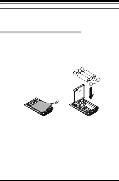
INSTALLATION OF FBA-39 ALKALINE BATTERY CASE (OPTION)
The optional FBA-39 Battery Case allows receive monitoring using three “AA” size Alkaline batteries. Alkaline batteries can also be used for low power transmission in an emergency. The power output will only be selectable 1 W/50 mW (for 50/144/430 MHz FM) or 500 mW/50 mW (for 222 MHz FM), or 1 W fixed (for 50 MHz AM).
TO INSTALL ALKALINE BATTERIES INTO THE FBA-39
1.Lift up the lower right corner of the rubber cover, and then open the cover (Figure 1).
2.Referring to Figure 2, slide the batteries into the FBA-39 as shown in the illustration, with the Negative [–] side of the batteries touching the spring connections inside the
FBA-39.
3.Close the rubber cover.
4.Install the FBA-39 in the transceiver in the same manner as the FNB-101LI.
Figure 1 |
Figure 2 |
The FBA-39 does not provide connections for charging, since Alkaline cells cannot be re-charged. Therefore, the NC-86B/C, E-DC-5B, or E-DC-6 may safely be connected to the EXT DC jack when the FBA-39 is installed.
Notes:
The FBA-39 is designed for use only with AA-type Alkaline cells.
If you do not use the VX-8DR for a long time, remove the Alkaline batteries from the FBA-39, as battery leakage could cause damage to the FBA-39 and/or the transceiver.
VX-8DR OPERATING MANUAL |
11 |
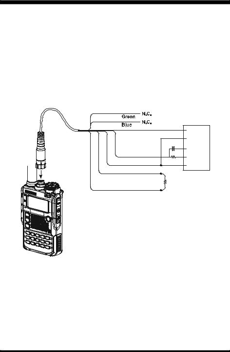
INTERFACE OF PACKET TNCS
The VX-8DR may be used for Packet operation, using the optional CT-M11 MIC/SP Connection Cable (available from your Yaesu dealer) for easy interconnection to com- monly-available connectors wired to your TNC.
The audio level from the receiver to the TNC may be adjusted by rotating the DIAL knob while pressing and holding the  key, as with voice operation. The input level to the VX-8DR from the TNC should be adjusted at the TNC side; the optimum input voltage is approximately 5 mV at 2000 Ohms.
Be sure to turn the transceiver and TNC off before connecting the cables, to prevent voltage spikes from damaging your transceiver.
CT-M11 MIC/SP Connection Cable
Brown
Orange
Red
Black
Gray
TNC
 SP
SP
 GND
GND
10 µF
 MIC
MIC

 PTT 2 kΩ
 GND
GND
22 kΩ
If you wish to disable the
VX-8R internal speaker while packet operation, connect a 22 kΩ resistor between wires Black and Gray.
12 |
VX-8DR OPERATING MANUAL |
OPERATION
Hi! I’m R. F. Radio, and I’ll be helping you along as you learn the many features of the VX-8DR. I know you’re anxious to get on the air, but I encourage you to read the “Operation” section of this manual as thoroughly as
possible, so you’ll get the most out of this fantastic new transceiver. Now. . .let’s get operating!
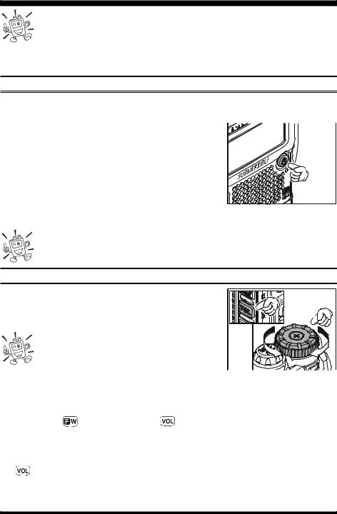
SWITCHING POWER ON AND OFF
1.Be sure the battery pack is installed, and that it is fully charged. Connect the antenna to the top panel ANTENNA jack.
2.Press and hold in the  (PWR) switch (on the right
  side of the front panel) for 2 seconds. Two beeps will be
heard when the switch has been held long enough. The
opening message will appear briefly on the display, then the frequency display will appear. After another two sec-
onds, the receive-mode Battery Saver function will become active, unless you have disabled it (see page 125).
3. To turn the VX-8DR off, press and hold in the  (PWR) switch again for 2 seconds.
If you don’t hear the two “Beep” tones when the radio comes on, the Beeper may have been disabled via the Menu system. See page 27, which tells you how to reactivate the Beeper.
ADJUSTING THE VOLUME LEVEL
Rotate the DIAL knob while pressing and holding the  key to set the desired audio level. Clockwise rotation increases the volume level.
1) The Volume level may be set on the “A-Band” and “B-Band” separately.
2) You may set the Audio Output Level to the Speaker, and the Earphone Output Level individually. The 
“SP VOLUME” notation appears in the S- & PO meter area while adjusting the Speaker Output Level. The “HP VOLUME” notation appears in the S- & PO meter area while
adjusting the Earphone Output Level. |
|
|
3) Pressing the |
key followed by the |
key, the DIAL knob function changes to |
the Volume Level adjustment instead of the frequency control. In this case, the “Volume Level Indicator” on the display blinks. Pressing the  key followed by the
  key again, returns the DIAL knob function to the frequency control. You may also change
the |
key function via Set Mode Item 107: VOLUME MODE. See page 133 for de- |
tails. |
|
VX-8DR OPERATING MANUAL |
13 |
OPERATION
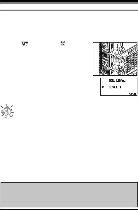
SQUELCH ADJUSTMENT
The VX-8DR’s Squelch system allows you to mute the background noise when no signal is being received. Not only does the Squelch system make “standby” operation more pleasant, it also significantly reduces battery current consumption.
The Squelch system may be adjusted independently for the FM and Wide-FM (FM Broadcast) modes.
1. |
Press the |
key, then press the |
key on the left |
|
side of the radio. This provides a “Short-cut” to Set |
||
|
Mode Item 92: SQL LEVEL. |
|
|
2. |
Now, rotate the DIAL knob to the point where the back- |
||
|
ground noise is just silenced (typically at a setting of |
||
|
about “3” or “4” on the scale); this is the point of maxi- |
||
|
mum sensitivity to weak signals. |
|
|
3.When you are satisfied with the Squelch threshold setting,  press the PTT key briefly to save the new setting and exit to
normal operation.
4. You may also adjust the Squelch setting by using the “Set” (Menu) mode. See page 157 for details.
1) The Squelch level may be set on the “Main” and “Sub” bands separately. 2) If you’re operating in an area of high RF pollution, you may need to consider “Tone Squelch” operation using the built-in CTCSS Decoder. This
feature will keep your radio quiet until a call is received from a station sending a carrier which contains a matching (sub audible) CTCSS tone. Or if your friends have radios equipped with DCS (Digital Coded Squelch) like your VX-8DR, try using that mode for silent monitoring of busy channels.
24-HOUR CLOCK
The VX-8DR has a 24-hour clock with a calendar which covers all dates from January 1, 2000 through December 31, 2099. Set the clock according to the “Clock Set” column on page 120.
14 |
VX-8DR OPERATING MANUAL |
OPERATION
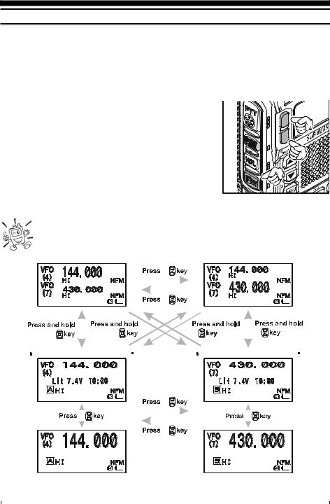
SELECTING THE OPERATING BAND
In the factory default configuration, the VX-8DR operates in the “Dual Receive” mode.
During Dual Receive operation, the “A-Band” frequency will be displayed on the upper part of the LCD, and the “B-Band” frequency will be displayed on the lower part. The “Operating” band (the band on which transmission and band/frequency changes are possible) is shown in large characters, and “Receive only” band is shown in small characters.
Press the  key briefly to engage the “A-Band” fre-
  quency as the “Operating” band. Alternatively, press the
 key briefly to engage the “B-Band” frequency, as described previously.
Press and hold in the  or
or  key for 1/2 seconds to switch to Mono Band Operation. During Mono band operation, you may change the display between “double-size character” and “large character” by pressing the
  /
/ key.
key.
When monitoring the receive audio with stereo earphones, the audio from the “A-Band” is only heard in the left ear, and the audio from the “B-Band” is only heard in the right ear.
|
|
|
|
|
|
|
|
|
|
|
|
|
|
|
|
|
|
|
|
|
|
|
|
|
|
|
|
|
|
|
|
|
|
|
|
|
|
|
|
|
|
|
|
|
|
|
|
|
|
|
|
|
|
|
|
|
|
|
|
|
|
|
|
|
|
|
|
|
|
|
|
|
|
|
|
|
|
|
|
|
|
|
|
|
|
|
|
|
|
|
|
|
|
|
|
|
|
|
|
|
|
|
|
|
|
|
|
|
|
|
|
|
|
|
|
|
|
|
|
|
|
|
|
|
|
|
|
|
|
|
|
|
|
|
|
|
|
|
|
|
|
|
|
|
|
|
|
|
|
|
|
|
|
|
|
|
|
|
|
|
|
|
|
|
|
|
|
|
|
|
|
|
|
|
|
|
|
|
|
|
|
|
|
|
|
|
|
|
|
|
|
|
|
|
|
|
|
|
|
|
|
|
|
|
|
|
|
|
|
|
|
|
|
|
|
|
|
|
|
|
|
|
|
|
|
|
|
|
|
|
|
|
|
|
|
|
|
|
|
|
|
|
|
|
|
|
|
|
|
|
|
|
|
|
|
|
|
|
|
|
|
|
|
|
|
|
|
|
|
|
|
|
|
|
|
|
|
|
|
|
|
|
|
|
|
|
|
|
|
|
|
|
|
|
|
|
|
|
|
|
|
|
|
|
|
|
|
|
|
|
|
|
|
|
|
|
|
|
|
|
|
|
|
|
|
|
|
|
|
|
|
|
|
|
|
|
|
|
|
|
|
|
|
|
|
|
|
|
|
|
|
|
|
|
|
|
|
|
|
|
|
|
|
|
|
|
|
|
|
|
|
|
|
|
|
|
|
|
|
|
|
|
|
|
|
|
|
|
|
|
|
|
|
|
|
|
|
|
|
|
|
|
|
|
|
|
|
|
|
|
|
|
|
|
|
|
|
|
|
|
|
|
|
|
|
|
|
|
|
|
|
|
|
|
|
|
|
|
|
|
|
|
|
|
|
|
|
|
|
|
|
|
|
|
|
|
|
|
|
|
|
|
|
|
|
|
|
|
|
|
|
|
|
|
|
|
|
|
|
|
|
|
|
|
|
|
|
|
|
|
|
|
|
|
|
|
|
|
|
|
|
|
|
|
|
|
|
|
|
|
|
|
|
|
|
|
|
|
|
|
|
|
|
|
|
|
|
|
|
|
|
|
|
|
|
|
|
|
|
|
|
|
|
|
|
|
|
|
|
|
|
|
|
|
|
|
|
|
|
|
|
|
|
|
|
|
|
|
|
|
|
|
|
|
|
|
|
|
|
|
|
|
|
|
|
|
|
|
|
|
|
|
|
|
|
|
|
|
|
|
|
|
|
|
|
|
|
|
|
|
|
|
|
|
|
|
|
|
|
|
|
|
|
|
|
|
|
|
|
|
|
|
|
|
|
|
|
|
|
|
|
|
|
|
|
|
|
|
|
|
|
|
|
|
|
|
|
|
|
|
|
|
|
|
|
|
|
|
|
|
|
|
|
|
|
|
|
|
|
|
|
|
|
|
|
|
|
|
|
|
|
|
|
|
|
|
|
|
|
|
|
|
|
|
|
|
|
|
|
|
|
|
|
|
|
|
|
|
|
|
|
|
|
|
|
|
|
|
|
|
|
|
|
|
|
|
|
|
|
|
|
|
|
|
|
|
|
|
|
|
|
|
|
|
|
|
|
|
|
|
|
|
|
|
|
|
|
|
|
|
|
|
|
|
|
|
|
|
|
|
|
|
|
|
|
|
|
|
|
|
|
|
|
|
|
|
|
|
|
|
|
|
|
|
|
|
|
|
|
|
|
|
|
|
|
|
|
|
|
|
|
|
|
|
|
|
|
|
|
|
|
|
|
|
|
|
|
|
|
|
|
|
|
|
|
|
|
|
|
|
|
|
|
|
|
|
|
|
|
|
|
|
|
|
|
|
|
|
|
|
|
|
|
|
|
|
|
|
|
|
|
|
|
|
|
|
|
|
|
|
|
|
|
|
|
|
|
|
|
|
|
|
|
|
|
|
|
|
|
|
|
|
|
|
|
|
|
|
|
|
|
|
|
|
|
|
|
|
|
|
|
|
|
|
|
|
|
|
|
|
|
|
|
|
|
|
|
|
|
|
|
|
|
|
|
|
|
|
|
|
|
|
|
|
|
|
|
|
|
|
|
|
|
|
|
|
|
|
|
|
|
|
|
|
|
|
|
|
|
|
|
|
|
|
|
|
|
|
|
|
|
|
|
|
|
|
|
|
|
|
|
|
|
|
|
|
|
|
|
|
|
|
|
|
|
|
|
|
|
|
|
|
|
|
|
|
|
|
|
|
|
|
|
|
|
|
|
|
|
|
|
|
|
|
|
|
|
|
|
|
|
|
|
|
|
|
|
|
|
|
|
|
|
|
|
|
|
|
|
|
|
|
|
|
|
|
|
|
|
|
|
|
|
|
|
|
|
|
|
|
|
|
|
|
|
|
|
|
|
|
|
|
|
|
|
|
|
|
|
|
|
|
|
|
|
|
|
|
|
|
|
|
|
|
|
|
|
|
|
|
|
|
|
|
|
|
|
|
|
|
|
|
|
|
|
|
|
|
|
|
|
|
|
|
|
|
|
|
|
|
|
|
|
|
|
|
|
|
|
|
|
|
|
|
|
|
|
|
|
|
|
|
|
|
|
|
|
|
|
|
|
|
|
|
|
|
|
|
|
|
|
|
|
|
|
|
|
|
|
|
|
|
|
|
|
|
|
|
|
|
|
|
|
|
|
|
|
|
|
|
|
|
|
|
|
|
|
|
|
|
|
|
|
|
|
|
|
|
|
|
|
|
|
|
|
|
|
|
|
|
|
|
|
|
|
|
|
|
|
|
|
|
|
|
|
|
|
|
|
|
|
|
|
|
|
|
|
|
|
|
|
|
|
|
|
|
|
|
|
|
|
|
|
|
|
|
|
|
|
|
|
|
|
|
|
|
|
|
|
|
|
|
|
|
|
|
|
|
|
|
|
|
|
|
|
|
|
|
|
|
|
|
|
|
|
|
|
|
|
|
|
|
|
|
|
|
|
|
|
|
|
|
|
|
|
|
|
|
|
|
|
|
|
|
|
|
|
|
|
|
|
|
|
|
|
|
|
|
|
|
|
|
|
|
|
|
|
|
|
|
|
|
|
|
|
|
|
|
|
|
|
|
|
|
|
|
|
|
|
|
|
|
|
|
|
|
|
|
|
|
|
|
|
|
|
|
|
|
|
|
|
|
|
|
|
|
|
|
|
|
|
|
|
|
|
|
|
|
|
|
|
|
|
|
|
|
|
|
|
|
|
|
|
|
|
|
|
|
|
|
|
|
|
|
|
|
|
|
|
|
|
|
|
|
|
|
|
|
|
|
|
|
|
|
|
|
|
|
|
|
|
|
|
|
|
|
|
|
|
|
|
|
|
|
|
|
|
|
|
|
|
|
|
|
|
|
|
|
|
|
|
|
|
|
|
|
|
|
|
|
|
|
|
|
|
|
|
|
|
|
|
|
|
|
|
|
|
|
|
|
|
|
|
|
|
|
|
|
|
|
|
|
|
|
|
|
|
|
|
|
|
|
|
|
|
|
|
|
|
|
|
|
|
|
|
|
|
|
|
|
|
|
|
|
|
|
|
|
|
|
|
|
|
|
|
|
|
|
|
|
|
|
|
|
|
|
|
|
|
|
|
|
|
|
|
|
|
|
|
|
|
|
|
|
|
|
|
|
|
|
|
|
|
|
|
|
|
|
|
|
|
|
|
|
|
|
|
|
|
|
|
|
|
|
|
|
|
|
|
|
|
|
|
|
|
|
|
|
|
|
|
|
|
|
|
|
|
|
|
|
|
|
|
|
|
|
|
|
|
|
|
|
|
|
|
|
|
|
|
|
|
|
|
|
|
|
|
|
|
|
|
|
|
|
|
|
|
|
|
|
|
|
|
|
|
|
|
|
|
|
|
|
|
|
|
|
|
|
|
|
|
|
|
|
|
|
|
|
|
|
|
|
|
|
|
|
|
|
|
|
|
|
|
|
|
|
|
|
|
|
|
|
|
|
|
|
|
|
|
|
|
|
|
|
|
|
|
|
|
|
|
|
|
|
|
|
|
|
|
|
|
|
|
|
|
|
|
|
|
|
|
|
|
|
|
|
|
|
|
|
|
|
|
|
|
|
|
|
|
|
|
|
|
|
|
|
|
|
|
|
|
|
|
|
|
|
|
|
|
|
|
|
|
|
|
|
|
|
|
|
|
|
|
|
|
|
|
|
|
|
|
|
|
|
|
|
|
|
|
|
|
|
|
|
|
|
|
|
|
|
|
|
|
|
|
|
|
|
|
|
|
|
|
|
|
|
|
|
|
|
|
|
|
|
|
|
|
|
|
|
|
|
|
|
|
|
|
|
|
|
|
|
|
|
|
|
|
|
|
|
|
|
|
|
|
|
|
|
|
|
|
|
|
|
|
|
|
|
|
|
|
|
|
|
|
|
|
|
|
|
|
|
|
|
|
|
|
|
|
|
|
|
|
|
|
|
|
|
|
|
|
|
|
|
|
|
|
|
|
|
|
|
|
|
|
|
|
|
|
|
|
|
|
|
|
|
|
|
|
|
|
|
|
|
|
|
|
|
|
|
|
|
|
|
|
|
|
|
|
|
|
|
|
|
|
|
|
|
|
|
|
|
|
|
|
|
|
|
|
|
|
|
|
|
|
|
|
|
|
|
|
|
|
|
|
|
|
|
|
|
|
|
|
|
|
|
|
|
|
|
|
|
|
|
|
|
|
|
|
|
|
|
|
|
|
|
|
|
|
|
|
|
|
|
|
|
|
|
|
|
|
|
|
|
|
|
|
|
|
|
|
|
|
|
|
|
|
|
|
|
|
|
|
|
|
|
|
|
|
|
|
|
|
|
|
|
|
|
|
|
|
|
|
|
|
|
|
|
|
|
|
|
|
|
|
|
|
|
|
|
|
|
|
|
|
|
|
|
|
|
|
|
|
|
|
|
|
|
|
|
|
|
|
|
|
|
|
|
|
|
|
|
|
|
|
|
|
|
|
|
|
|
|
|
|
|
|
|
|
|
|
|
|
|
|
|
|
|
|
|
|
|
|
|
|
|
|
|
|
|
|
|
|
|
|
|
|
|
|
|
|
|
|
|
|
|
|
|
|
|
|
|
|
|
|
|
|
|
|
|
|
|
|
|
|
|
|
|
|
|
|
|
|
|
|
|
|
|
|
|
|
|
|
|
|
|
|
|
|
|
|
|
|
|
|
|
|
|
|
|
|
|
|
|
|
|
|
|
|
|
|
|
|
|
|
|
|
|
|
|
|
|
|
|
|
|
|
|
|
|
|
|
|
|
|
|
|
|
|
|
|
|
|
|
|
|
|
|
|
|
|
|
|
|
|
|
|
|
|
|
|
|
|
|
|
|
|
|
|
|
|
|
|
|
|
|
|
|
|
|
|
|
|
|
|
|
|
|
|
|
|
|
|
|
|
|
|
|
|
|
|
|
|
|
|
|
|
|
|
|
|
|
|
|
|
|
|
|
|
|
|
|
|
|
|
|
|
|
|
|
|
|
|
|
|
|
|
|
|
|
|
|
|
|
|
|
|
|
|
|
|
|
|
|
|
|
|
|
|
|
|
|
|
|
|
|
|
|
|
|
|
|
|
|
|
|
|
|
|
|
|
|
|
|
|
|
|
|
|
|
|
|
|
|
|
|
|
|
|
|
|
|
|
|
|
|
|
|
|
|
|
|
|
|
|
|
|
|
|
|
|
|
|
|
|
|
|
|
|
|
|
|
|
|
|
|
|
|
|
|
|
|
|
|
|
|
|
|
|
|
|
|
|
|
|
|
|
|
|
|
|
|
|
|
|
|
|
|
|
|
|
|
|
|
|
|
|
|
|
|
|
|
|
|
|
|
|
|
|
|
|
|
|
|
|
|
|
|
|
|
|
|
|
|
|
|
|
|
|
|
|
|
|
|
|
|
|
|
|
|
|
|
|
|
|
|
|
|
|
|
|
|
|
|
|
|
|
|
|
|
|
|
|
|
|
|
|
|
|
|
|
|
|
|
|
|
|
|
|
|
|
|
|
|
|
|
|
|
|
|
|
|
|
|
|
|
|
|
|
|
|
|
|
|
|
|
|
|
|
|
|
|
|
|
|
|
|
|
|
|
|
|
|
|
|
|
|
|
|
|
|
|
|
|
|
|
|
|
|
|
|
|
|
|
|
|
|
|
|
|
|
|
|
|
|
|
|
|
|
|
|
|
|
|
|
|
|
|
|
|
|
|
|
|
|
|
|
|
|
|
|
|
|
|
|
|
|
|
|
|
|
|
|
|
|
|
|
|
|
|
|
|
|
|
|
|
|
|
|
|
|
|
|
|
|
|
|
|
|
|
|
|
|
|
|
|
|
|
|
|
|
|
|
|
|
|
|
|
|
|
|
|
|
|
|
|
|
|
|
|
|
|
|
|
|
|
|
|
|
|
|
|
|
|
|
|
|
|
|
|
|
|
|
|
|
|
|
|
|
|
|
|
|
|
|
|
|
|
|
|
|
|
|
|
|
|
|
|
|
|
|
|
|
|
|
|
|
|
|
|
|
|
|
|
|
|
|
|
|
|
|
|
|
|
|
|
|
|
|
|
|
|
|
|
|
|
|
|
|
|
|
|
|
|
|
|
|
|
|
|
|
|
|
|
|
|
|
|
|
|
|
|
|
|
|
|
|
|
|
|
|
|
|
|
|
|
|
|
|
|
|
|
|
|
|
|
|
|
|
|
|
|
|
|
|
|
|
|
|
|
|
|
|
|
|
|
|
|
|
|
|
|
|
|
|
|
|
|
|
|
|
|
|
|
|
|
|
|
|
|
|
|
|
|
|
|
|
|
|
|
|
|
|
|
|
|
|
|
|
|
|
|
|
|
|
|
|
|
|
|
|
|
|
|
|
|
|
|
|
|
|
|
|
|
|
|
|
|
|
|
|
|
|
|
|
|
|
|
|
|
|
|
|
|
|
|
|
|
|
|
|
|
|
|
|
|
|
|
|
|
|
|
|
|
|
|
|
|
|
|
|
|
|
|
|
|
|
|
|
|
|
|
|
|
|
|
|
|
|
|
|
|
|
|
|
|
|
|
|
|
|
|
|
|
|
|
|
|
|
|
|
|
|
|
|
|
|
|
|
|
|
|
|
|
|
|
|
|
|
|
|
|
|
|
|
|
|
|
|
|
|
|
|
|
|
|
|
|
|
|
|
|
|
|
|
|
|
|
|
|
|
|
|
|
|
|
|
|
|
|
|
|
|
|
|
|
|
|
|
|
|
|
|
|
|
|
|
|
|
|
|
|
|
|
|
|
|
|
|
|
|
|
|
|
|
|
|
|
|
|
|
|
|
|
|
|
|
|
|
|
|
|
|
|
|
|
|
|
|
|
|
|
|
|
|
|
|
|
|
|
|
|
|
|
|
|
|
|
|
|
|
|
|
|
|
|
|
|
|
|
|
|
|
|
|
|
|
|
|
|
|
|
|
|
|
|
|
|
|
|
|
|
|
|
|
|
|
|
|
|
|
|
|
|
|
|
|
|
|
|
|
|
|
|
|
|
|
|
|
|
|
|
|
|
|
|
|
|
|
|
|
|
|
|
|
|
|
|
|
|
|
|
|
|
|
|
|
|
|
|
|
|
|
|
|
|
|
|
|
|
|
|
|
|
|
|
|
|
|
|
|
|
|
|
|
|
|
|
|
|
|
|
|
|
|
|
|
|
|
|
|
|
|
|
|
|
|
|
|
|
|
|
|
|
|
|
|
|
|
|
|
|
|
|
|
|
|
|
|
|
|
|
|
|
|
|
|
|
|
|
|
|
|
|
|
|
|
|
|
|
|
|
|
|
|
|
|
|
|
|
|
|
|
|
|
|
|
|
|
|
|
|
|
|
|
|
|
|
|
|
|
|
|
|
|
|
|
|
|
|
|
|
|
|
|
|
|
|
|
|
|
|
|
|
|
|
|
|
|
|
|
|
|
|
|
|
|
|
|
|
|
|
|
|
|
|
|
|
|
|
|
|
|
|
|
|
|
|
|
|
|
|
|
|
|
|
|
|
|
|
|
|
|
|
|
|
|
|
|
|
|
|
|
|
|
|
|
|
|
|
|
|
|
|
|
|
|
|
|
|
|
|
|
|
|
|
|
|
|
|
|
|
|
|
|
|
|
|
|
|
|
|
|
|
|
|
|
|
|
|
|
|
|
|
|
|
|
|
|
|
|
|
|
|
|
|
|
|
|
|
|
|
|
|
|
|
|
|
|
|
|
|
|
|
|
|
|
|
|
|
|
|
|
|
|
|
|
|
|
|
|
|
|
|
|
|
|
|
|
|
|
|
|
|
|
|
|
|
|
|
|
|
|
|
|
|
|
|
|
|
|
|
|
|
|
|
|
|
|
|
|
|
|
|
|
|
|
|
|
|
|
|
|
|
|
|
|
|
|
|
|
|
|
|
|
|
|
|
|
|
|
|
|
|
|
|
|
|
|
|
|
|
|
|
|
|
|
|
|
|
|
|
|
|
|
|
|
|
|
|
|
|
|
|
|
|
|
|
|
|
|
|
|
|
|
|
|
|
|
|
|
|
|
|
|
|
|
|
|
|
|
|
|
|
|
|
|
|
|
|
|
|
|
|
|
|
|
|
|
|
|
|
|
|
|
|
|
|
|
|
|
|
|
|
|
|
|
|
|
|
|
|
|
|
|
|
|
|
|
|
|
|
|
|
|
|
|
|
|
|
|
|
|
|
|
|
|
|
|
|
|
|
|
|
|
|
|
|
|
|
|
|
|
|
|
|
|
|
|
|
|
|
|
|
|
|
|
|
|
|
|
|
|
|
|
|
|
|
|
|
|
|
|
|
|
|
|
|
|
|
|
|
|
|
|
|
|
|
|
|
|
|
|
|
|
|
|
|
|
|
|
|
|
|
|
|
|
|
|
|
|
|
|
|
|
|
|
|
|
|
|
|
|
|
|
|
|
|
|
|
|
|
|
|
|
|
|
|
|
|
|
|
|
|
|
|
|
|
|
|
|
|
|
|
|
|
|
|
|
|
|
|
|
|
|
|
|
|
|
|
|
|
|
|
|
|
|
|
|
|
|
|
|
|
|
|
|
|
|
|
|
|
|
|
|
|
|
|
|
|
|
|
|
|
|
|
|
|
|
|
|
|
|
|
|
|
|
|
|
|
|
|
|
|
|
|
|
|
|
|
|
|
|
|
|
|
|
|
|
|
|
|
|
|
|
|
|
|
|
|
|
|
|
|
|
|
|
|
|
|
|
|
|
|
|
|
|
|
|
|
|
|
|
|
|
|
|
|
|
|
|
|
|
|
|
|
|
|
|
|
|
|
|
|
|
|
|
|
|
|
|
|
|
|
|
|
|
|
|
|
|
|
|
|
|
|
|
|
|
|
|
|
|
|
|
|
|
|
|
|
|
|
|
|
|
|
|
|
|
|
|
|
|
|
|
|
|
|
|
|
|
|
|
|
|
|
|
|
|
|
|
|
|
|
|
|
|
|
|
|
|
|
|
|
|
|
|
|
|
|
|
|
|
|
|
|
|
|
|
|
|
|
|
|
|
|
|
|
|
|
|
|
|
|
|
|
|
|
|
|
|
|
|
|
|
|
|
|
|
|
|
|
|
|
|
|
|
|
|
|
|
|
|
|
|
|
|
|
|
|
|
|
|
|
|
|
|
|
|
|
|
|
|
|
|
|
|
|
|
|
|
|
|
|
|
|
|
|
|
|
|
|
|
|
|
|
|
|
|
|
|
|
|
|
|
|
|
|
|
|
|
|
|
|
|
|
|
|
|
|
|
|
|
|
|
|
|
|
|
|
|
|
|
|
|
|
|
|
|
|
|
|
|
|
|
|
|
|
|
|
|
|
|
|
|
|
|
|
|
|
|
|
|
|
|
|
|
|
|
|
|
|
|
|
|
|
|
|
|
|
|
|
|
|
|
|
|
|
|
|
|
|
|
|
|
|
|
|
|
|
|
|
|
|
|
|
|
|
|
|
|
|
|
|
|
|
|
|
|
|
|
|
|
|
|
|
|
|
|
|
|
|
|
|
|
|
|
|
|
|
|
|
|
|
|
|
|
|
|
|
|
|
|
|
|
|
|
|
|
|
|
|
|
|
|
|
|
|
|
|
|
|
|
|
|
|
|
|
|
|
|
|
|
|
|
|
|
|
|
|
|
|
|
|
|
|
|
|
|
|
|
|
|
|
|
|
|
|
|
|
|
|
|
|
|
|
|
|
|
|
|
|
|
|
|
|
|
|
|
|
|
|
|
|
|
|
|
|
|
|
|
|
|
|
|
|
|
|
|
|
|
|
|
|
|
|
|
|
|
|
|
|
|
|
|
|
|
|
|
|
|
|
|
|
|
|
|
|
|
|
|
|
|
|
|
|
|
|
|
|
|
|
|
|
|
|
|
|
|
|
|
|
|
|
|
|
|
|
|
|
|
|
|
|
|
|
|
|
|
|
|
|
|
|
|
|
|
|
|
|
|
|
|
|
|
|
|
|
|
|
|
|
|
|
|
|
|
|
|
|
|
|
|
|
|
|
|
|
|
|
|
|
|
|
|
|
|
|
|
|
|
|
|
|
|
|
|
|
|
|
|
|
|
|
|
|
|
|
|
|
|
|
|
|
|
|
|
|
|
|
|
|
|
|
|
|
|
|
|
|
|
|
|
|
|
|
|
|
|
|
|
|
|
|
|
|
|
|
|
|
|
|
|
|
|
|
|
|
|
|
|
|
|
|
|
|
|
|
|
|
|
|
|
|
|
|
|
|
|
|
|
|
|
|
|
|
|
|
|
|
|
|
|
|
|
|
|
|
|
|
|
|
|
|
|
|
|
|
|
|
|
|
|
|
|
|
|
|
|
|
|
|
|
|
|
|
|
|
|
|
|
|
|
|
|
|
|
|
|
|
|
|
|
|
|
|
|
|
|
|
|
|
|
|
|
|
|
|
|
|
|
|
|
|
|
|
|
|
|
|
|
|
|
|
|
|
|
|
|
|
|
|
|
|
|
|
|
|
|
|
|
|
|
|
|
|
|
|
|
|
|
|
|
|
|
|
|
|
|
|
|
|
|
|
|
|
|
|
|
|
|
|
|
|
|
|
|
|
|
|
|
|
|
|
|
|
|
|
|
|
|
|
|
|
|
|
|
|
|
|
|
|
|
|
|
|
|
|
|
|
|
|
|
|
|
|
|
|
|
|
|
|
|
|
|
|
|
|
|
|
|
|
|
|
|
|
|
|
|
|
|
|
|
|
|
|
|
|
|
|
|
|
|
|
|
|
|
|
|
|
|
|
|
|
|
|
|
|
|
|
|
|
|
|
|
|
|
|
|
|
|
|
|
|
|
|
|
|
|
|
|
|
|
|
|
|
|
|
|
|
|
|
|
|
|
|
|
|
|
|
|
|
|
|
|
|
|
|
|
|
|
|
|
|
|
|
|
|
|
|
|
|
|
|
|
|
|
|
|
|
|
|
|
|
|
|
|
|
|
|
|
|
|
|
|
|
|
|
|
|
|
|
|
|
|
|
|
|
|
|
|
|
|
|
|
|
|
|
|
|
|
|
|
|
|
|
|
|
|
|
|
|
|
|
|
|
|
|
|
|
|
|
|
|
|
|
|
|
|
|
|
|
|
|
|
|
|
|
|
|
|
|
|
|
|
|
|
|
|
|
|
|
|
|
|
|
|
|
|
|
|
|
|
|
|
|
|
|
|
|
|
|
|
|
|
|
|
|
|
|
|
|
|
|
|
|
|
|
|
|
|
|
|
|
|
|
|
|
|
VX-8DR OPERATING MANUAL |
15 |
|||||||||||||||||||||||||||||||||||||||||||||||||||||||||||||||||||||||||||||||||||||||||||||||||||||||||||||||||
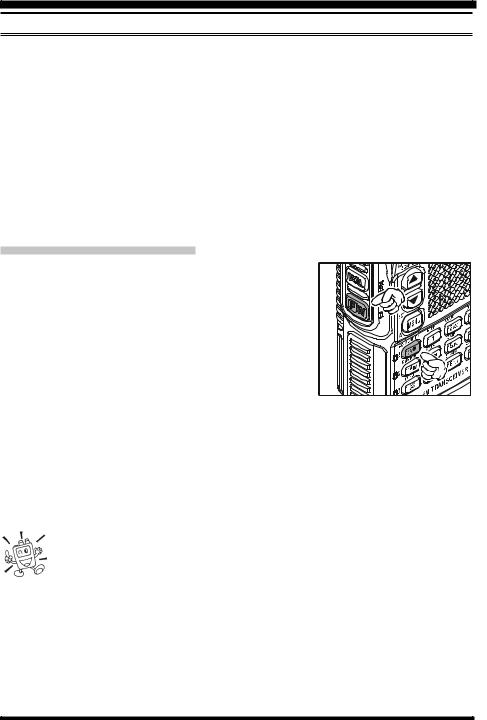
OPERATION
SELECTING THE FREQUENCY BAND
The VX-8DR covers an incred- |
OPERATING BAND |
FREQUENCY RANGE |
||
|
||||
ibly wide frequency range, over |
[BAND NUMBER] |
“VFO-A” |
“VFO-B” |
|
which a number of different op- |
SW Band [1] |
1.8-30 MHz |
– |
|
50 MHz Band [2] |
30-76 MHz |
30-76 MHz |
||
erating modes are used. There- |
||||
AIR Band [3] |
108-137 MHz |
108-137 MHz |
||
|
||||
fore, the VX-8DR’s frequency |
VHF HAM Band [4] |
137-174 MHz |
137-174 MHz |
|
coverage has been divided into |
VHF TV Band [5] |
174-222 MHz |
174-222 MHz |
|
different operating bands. Each |
INFO 1 Band [6] |
222-420 MHz |
222-420 MHz |
|
UHF HAM Band [7] |
420-470 MHz |
420-470 MHz |
||
band has its own preset channel |
UHF TV Band [8] |
470-774 MHz |
470-580 MHz |
|
steps and operating modes. You |
INFO 2 Band [9] |
774-999.99 MHz |
– |
|
can change the channel steps and |
|
USA Version: Cellular Blocked |
||
|
|
|
||
operating modes later, if you like (see page 29).
TO CHANGE OPERATING BANDS
1.Press the  key repeatedly. You will see the LCD indication change to a higher frequency band each time you press the
  key. A Band Number according to the receiving frequency is also displayed.
2.If you wish to move the operating band selection down-
ward (toward lower frequencies), press the  key first, then press the
  key.
key.
3.The VX-8DR uses a dual VFO system (described pre-
viously). To switch TX/RX operation from the “VFO-A” to the “VFO-B” instantly, press the  key briefly. Pressing the
  key will return TX/RX operation to “VFO-A”. The frequency band shown in “Large” characters is the band on which
transmission is possible; the band shown in “Small” characters may only be used for reception.
4.Once you have selected the desired band, you may initiate manual tuning (or scanning). See the discussions on the next page.
1)SW Band and Information Band reception is only possible on the “VFO-A”.
2)The VX-8DR has an AM/FM Broadcast band radio. You can receive these bands independently. See page 22 for details.
3) If desired, you may omit (skip) one or more bands from the band selection loop for faster recall of your favorite operating bands. See page 132 for details.
16 |
VX-8DR OPERATING MANUAL |
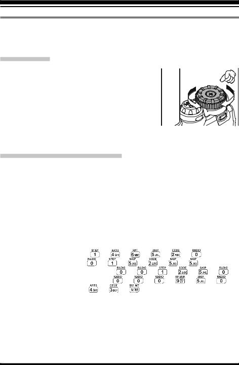
OPERATION
FREQUENCY NAVIGATION
The VX-8DR will initially be operating in the “VFO” mode, as just described. This is a frequency step system which allows free tuning throughout the currently-selected operating band.
Three basic frequency navigation methods are available on the VX-8DR:
1) TUNING DIAL
Rotation of the DIAL knob allows tuning in the pre-pro-  grammed steps established for the current operating band.
Clockwise rotation of the DIAL knob causes the VX-8DR to be tuned toward a higher frequency, while counter-clock- wise rotation will lower the operating frequency.
If you press the  key briefly, then rotate the DIAL knob,
frequency steps of 1 MHz will be selected. This feature is  extremely useful for making rapid frequency excursions over the wide tuning range of the
VX-8DR.
2) DIRECT KEYPAD FREQUENCY ENTRY
The desired operating frequency may be entered directly from the keypad.
The operating mode will automatically be set once the new frequency is entered via the keypad.
To enter a frequency from the keypad, just press the numbered digits on the keypad in the proper sequence. There is no “Decimal point” key on the VX-8DR, so if the frequency is below 100 MHz (e.g. 15.150 MHz), any required leading zeroes must be entered. However, there is a short-cut for frequencies ending in zero - press the  key after the last non-zero digit.
Examples: |
|
|
|
|
|
|
|
To enter 146.520 MHz, press |
|
|
|
|
|
|
|
To enter 15.255 MHz, press |
|
|
|
|
|
|
|
To enter 1.250 |
MHz (1250 kHz), press |
|
|
|
|
|
|
To enter 0.950 |
MHz (950 kHz), press |
|
|
|
|
|
|
To enter 430.000MHz, press |
|
|
|
|
|
|
|
VX-8DR OPERATING MANUAL |
17 |
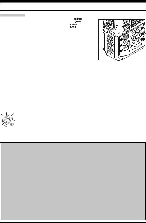
OPERATION
FREQUENCY NAVIGATION
3) SCANNING |
|
From the VFO mode, press and hold in the |
key for |
one second, and while still holding in the |
key, rotate |
the DIAL knob to select the bandwidth for the VFO scanner. Release the  key to begin scanning toward a higher frequency. The scanner will stop when it receives a signal strong enough to break through the Squelch threshold. The VX-8DR will then hold on that frequency according to the setting of the “RESUME” mode (Menu Item 83: SCAN RESUME).
If you wish to reverse the direction of the scan (i.e. toward a lower frequency, instead of a higher frequency), just rotate the DIAL knob one click in the counter-clockwise direction while the VX-8DR is scanning. The scanning direction will be reversed. To revert to scanning toward a higher frequency once more, rotate the DIAL knob one click clockwise.
Press the PTT switch briefly to cancel the scanning. See page 60 for more details regarding Scan Operation.
You may initiate upward or downward scanning by pressing and holding either  or
or  key for one second, respectively. In this case, the scanner scans the bandwidth that was previously selected.
Dual Receive Notice
The VX-8DR may receive very strong signals on the Image frequency, and/or the receiver sensitivity may be somewhat reduced by the combination of the “A-Band” and “B-Band” frequencies while Dual Receive operation is engaged.
If you experience interference that you suspect may be coming in via an “Image” path, you may calculate the possible frequencies using the formulas below. This information may be used in the design of effective countermeasures such as traps, etc.
9.8304 MHz x n |
11.7 MHz x n |
(n is an integer: 1, 2, 3, …) |
4.9152 MHz x n |
6.1440 MHz x n |
|
“A-Band” Freq. = (“B-Band” Freq. ± 46.35 MHz) x n
“B-Band” Freq. = (“A-Band” Freq. ± 47.25 MHz) x n (@ “A-Band” = NFM)
“B-Band” Freq. = (“A-Band” Freq. ± 45.8 MHz) x n (@ “A-Band” = WFM)
18 |
VX-8DR OPERATING MANUAL |
OPERATION
TRANSMISSION
Once you have set up an appropriate frequency inside one of the three (or four) Amateur bands on which the VX-8DR can transmit (50 MHz, 144 MHz, or 430 MHz, plus 222 MHz on the USA version), you’re ready to transmit. These are the most basic steps; more advanced aspects of transmitter operation will be discussed later.
1. |
To transmit, press the PTT switch, and speak into the |
||
|
front panel microphone (located in the lower right-hand |
||
|
corner of the speaker grille) in a normal voice level. |
||
|
The LED of the |
or |
which is designated the |
|
“Main” band will glow red during transmission. |
||
2. |
To return to the receive mode, release the PTT switch. |
||
3. |
During transmission, the relative power level will be |
||
|
indicated on the LCD. Additionally, the “L1”, “L2”, “L3”, |
||
|
or “HI” icon will appear at the left side of the PO meter, |
||
|
corresponding with the “Power” Level setting. |
||
1) If you’re just talking to friends in the immediate  area, you’ll get much longer battery life by switching to Low Power operation. To do this, press the
  key, then press the
  key so that the “Low
Power” icon appears at the bottom of the display. And don’t forget: always have an antenna connected when you transmit.
2) Transmission is not possible on “Sub” band and any operating bands other than the 50 MHz, 144 MHz, 222 MHz (USA version), and 430 MHz bands on the “Main” band.
CHANGING THE TRANSMITTER POWER LEVEL
You can select between a total of four transmitter power levels on your VX-8R. The exact power output will vary somewhat, depending on the voltage supplied to the transceiver. With the standard FNB-101LI Battery Pack and external DC source, the power output levels available are: “L1”, “L2”, “L3”, or “HI”
To change the power level:
1. The default setting for the power output is “High;” in this configuration, the display shows the “HI” icon. Pressing the  key, followed by the
  key, causes the power level “L1”, “L2”, or “L3” to appear.
2. Press the  key, followed by the
  key (repeatedly, if necessary) to make the “HI” icon appear and restore “High Power” operation.
VX-8DR OPERATING MANUAL |
19 |
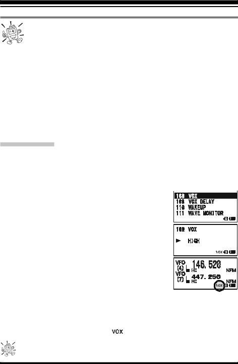
OPERATION
TRANSMISSION
1) The VX-8DR is smart! You can set up Low power on one band (like UHF), while leaving VHF on High power, and the radio will remember the different settings on each band. And when you store memories, you can store High
and Low power settings separately in each memory, so you don’t waste battery power when using very close-in repeaters!
2) When you are operating on one of the Low power settings, you can press the  key,
key,
then press the PTT switch, |
|
|
TRANSMIT POWER |
||
to cause the VX-8DR to |
OPERATING BAND |
FNB-101LI/-102LI or |
FBA-39 |
||
transmit (temporarily) on |
|
EXT DC (7.4 V) |
(w/Fresh Batteries) |
||
50/144/430 MHz |
HI: 5.0 |
W, L3: 2.5 W, |
L2: 1.0 W, |
||
High power. After one trans- |
|||||
|
FM |
L2: 1.0 |
W, L1: 0.05 W |
L1: 0.05 W |
|
mission, the power level will |
222 MHz FM |
HI: 1.5 |
W, L3: 1.0 W, |
L2: 0.5 W, |
|
revert to the previously-se- |
|
L2: 0.5 |
W, L1: 0.05 W |
L1: 0.05 W |
|
50 MHz AM |
1.0 W (Fixed) |
1.0 W (Fixed) |
|||
lected Low power setting. |
|||||
|
|
|
|
||
VOX OPERATION
The VOX system provides automatic transmit/receive switching based on voice input to the microphone. With the VOX system enabled, you do not need to press the PTT switch in order to transmit, and it is not necessary to use a VOX headset in order to utilize VOX operation.
1.Press and hold in the  key for one second to enter the Set mode.
2.Rotate the DIAL knob to select the Set Mode Item 108: 
VOX.
3. Press the  key briefly to enable adjustment of this Set Mode Item.
4. Rotate the DIAL knob to select the desired VOX Gain level (“HIGH” or “LOW”).
5. When you have made your choice, press the PTT switch to save the new setting and return to normal operation.
6. Without pressing the PTT switch, speak into the VX-8DR microphone in a normal voice level. When you start speaking, the transmitter should be activated automatically. When you finish speaking, the transceiver should return to the receive mode (after a short delay).
To cancel VOX and return to PTT operation, just repeat the above procedures, selecting “OFF” in step 4 above.
When the VOX system is activated, the “ |
” icon will appear on the display. |
The VOX is activated by the VX-8DR. The optional MH-74A7A Speaker/Microphone is ignored.
20 |
VX-8DR OPERATING MANUAL |

OPERATION
TRANSMISSION
Adjust the VOX “Hang-Time” (the transmit-receive delay after the cessation of speech) from the Set Mode Item 109: VOX DELAY. The default delay is 0.5 second. To set a different delay time:
1.Press and hold in the  key for one second to enter the Set mode.
2.Rotate the DIAL knob to select the Set Mode Item 109: 
VOX DELAY.
3. Press the  key briefly to enable adjustment of this Set Mode Item.
4. Rotate the DIAL knob to select the desired delay time (“0.5sec”, “1.0sec”, “1.5sec”, “2.0sec”, “2.5sec”, or “3.0sec”).
5.When you have made your choice, press the PTT switch to  save the new setting and return to normal operation.
VX-8DR OPERATING MANUAL |
21 |
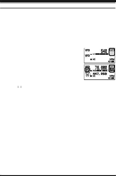
OPERATION
AM AND FM BROADCAST RECEPTION
The VX-8DR includes provision for reception of AM and FM broadcasts. FM broadcast reception, utilizes a wide-bandwidth filter and stereo decoder which provides excellent fidelity.
The AM and FM Broadcast reception is only possible on “VFO-A”.
1.Press the  key briefly to engage the “VFO-A” as the “Operating” band.
2.Press the  key, then press the
  key to enter the Broadcast Reception mode. The “
 ” icon will appear on the display while in the Broadcast Reception mode.
3.Press the  key to toggle the receiver between the “AM broadcast” and “FM broad-
cast” bands.  The AM broadcast coverage is 510 to 1790 kHz. The Band


 Number changes to “A” (which means AM) and an Operat-


ing Mode icon changes to “AM”.
The FM broadcast coverage is 76.00 to 107.90 MHz and utilizes Wide-FM mode. The Band Number changes to “F” (which means FM) and an Operating Mode icon changes to “WFM”.
4.Rotate the DIAL knob to select the desired station. When receiving an FM stereo signal, “


 ” icon will appear on the display.
5.To exit to normal operation, press the  key followed by the
  key.
key.
22 |
VX-8DR OPERATING MANUAL |

OPERATION
AM AND FM BROADCAST RECEPTION
ANTENNA SELECTION
To select the antenna for the AM Broadcast Reception:
1.Press and hold the  key for one second to enter the Set Mode.
2.Rotate the DIAL knob to select Set Mode Item 1: ANTENNA AM.
3.Press the  key briefly to enable the antenna selection.
4.Rotate the DIAL knob to select the AM antenna to be used: “BAR ANTENNA” (Uses the internal Bar Antenna) or “BAR & EXT” (Uses both the internal Bar Antenna and the Rubber Flex Antenna).
5.When you finish the selection, press the PTT switch to exit from the Menu mode and return to the Broadcast Reception mode.
To select the antenna for the FM Broadcast Reception:
1.Press and hold the  key for one second to enter the Set Mode.
2.Rotate the DIAL knob to select Set Mode Item 2: ANTENNA FM.
3.Press the  key briefly to enable the antenna selection.
4.Rotate the DIAL knob to select the antenna to be used:“EXT ANTENNA” (Uses the Rubber Flex Antenna) or “EAR PHONE” (Uses the Earphone Antenna).
5.When you finish the selection, press the PTT switch to exit from the Menu mode and return to the Broadcast Reception mode.
If you wish to output the audio of the FM Broadcast station to the VX-8DR internal speaker while using the earphone antenna, select Set Mode Item 90: SPEAKER OUT to “SPEAKER”.
VX-8DR OPERATING MANUAL |
23 |
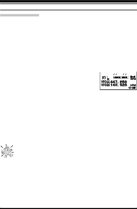
OPERATION
AM AND FM BROADCAST RECEPTION
AF-DUAL OPERATION
The AF-Dual Operation allows you to monitor two desired amateur band frequencies while also receiving an AM or FM broadcast station (Triple Watch functions!). When a signal is received in the amateur band, the amateur band audio is output instead of the AM or FM Broadcast station audio. When the amateur band signal drops, the AF-Dual Operation is resumed as determined by the user settings in the below procedures. Furthermore, you may transmit on the “Main” band amateur frequency by pressing the PTT switch at anytime. The “Main” band is selected by pressing the  /
/ key as usual.
1.Set the VX-8DR to the desired amateur band frequencies by the VFO or Memory channel selections on both “A-Band” and “B-Band”.
2.Select the “Main” Band you wish to use for transmit by pressing the  /
/ key.
key.
3.Press the  key, then press the
  key to activate the
AF Dual operation.
4. Press the  key to toggle the receiver between “AM broadcast” and “FM broadcast”.
5.Rotate the DIAL knob to tune the desired Broadcast station.
6.When a signal is received in the amateur band, the amateur band audio is output to the speaker. The AM or FM Broadcast station will no longer be heard. Two seconds after the amateur band signal drops, the AF-Dual Operation is resumed and the AM or FM Broadcast station will be heard from the speaker, while the amateur band frequencies are monitored. You may change the default resume time (two seconds) via Set Mode Item 77: RX AF DUAL. See the box on the next page.
7.You may monitor the amateur band frequencies forcibly by holding the  switch.
8.Press the PTT switch to transmit on the “Main” band.
9.To disable the AF-Dual Operation, press the  key, followed by the
  key.
key.
1)You may change the “Main” band by pressing the  /
/ key.
key.
2)You may change the “Main” band frequency by rotating the DIAL knob
while pressing the  switch.
3) When the  key is pressed, only the AM and FM Broadcast station memories are recalled.
24 |
VX-8DR OPERATING MANUAL |
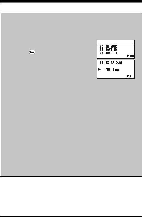
OPERATION
AM AND FM BROADCAST RECEPTION
SETTING THE AF-DUAL RESUME MODE
The VX-8DR allows you to select the resume mode of the AF-Dual Operation when a signal is received in the amateur band.
1.Press and hold the  key for one second to enter the Set Mode.
2.Rotate the DIAL knob to select Set Mode Item 77: 
RX AF DUAL. |
|
3. Press the |
key briefly to enable selection of this |
Menu Item.
4. Rotate the DIAL knob to select the desired resume mode of the AF-Dual Operation:
TX 1sec - TX 10sec: |
Sets the period of time |
||||||
|
after you transmit an |
|
|
|
|
||
|
|
|
|
|
|
|
|
|
|
|
|
||||
|
amateur signal before the AM or FM Broadcast sta- |
||||||
|
tion will be heard from the speaker, and the AF- |
||||||
|
Dual Operation is resumed. However, if a signal is |
||||||
|
received in the amateur band, the AF-Dual Opera- |
||||||
|
tion will halt on the amateur band frequency and |
||||||
|
the AF-Dual Operation does not resume. |
||||||
TRX 1sec - TXR 10sec: When the selected time passes after the amateur
|
band signal drops or transmission is over, the AM |
|
or FM Broadcast station will be heard from the |
|
speaker and the AF-Dual Operation is resumed. |
HOLD: |
When a signal is received in the amateur band or if |
|
you transmit on the amateur band, the AF-Dual Op- |
|
eration will halt on the amateur band frequency (the |
|
AF-Dual Operation does not resume.). You must |
|
manually re-initiate the AF-Dual Operation, if you |
|
wish to resume. |
5.When you have made your selection, press the PTT switch to save the new setting and resume normal mode.
VX-8DR OPERATING MANUAL |
25 |
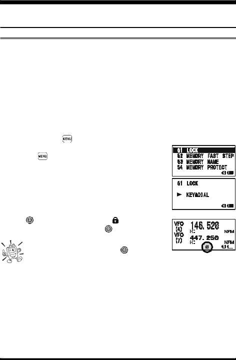
ADVANCED OPERATION
Now that you mastered the basics of VX-8DR operation, let’s learn more about some of the really neat features.
KEYBOARD LOCKING
In order to prevent accidental frequency change or inadvertent transmission, various keys and switches may be locked out. The possible lockout combinations are:
KEY: Just the front panel keys are locked out
DIAL: Just the top panel DIAL is locked out
KEY&DIAL: Both the DIAL knob and Keys are locked out
PTT: The PTT switch is locked (TX not possible)
KEY&PTT: Both the keys and PTT switch are locked out
DIAL&PTT: Both the DIAL knob and PTT switch are locked out
ALL: All of the above are locked out
To lock out some or all of the keys:
1. |
Press and hold the |
key for one second to enter the Set Mode. |
|
2. |
Rotate the DIAL knob to select Set Mode Item 51: LOCK. |
||
3. |
Press the |
key briefly to enable selection of this Menu |
|
|
Item. |
|
|
4. |
Rotate the DIAL knob to choose between one of the lock- |
||
|
ing schemes as outlined above. |
||
5.When you have made your selection, press the PTT switch to save the new setting and resume normal operation.
To activate the locking feature:
Press the |
|
(PWR) switch briefly. The “ |
” icon will appear |
|
|||||||||
|
|
||||||||||||
|
|
|
|
|
|
|
|||||||
on the LCD. To cancel locking, press the |
|
(PWR) switch again. |
|
|
|
|
|||||||
|
|
||||||||||||
|
|
|
|
|
|
|
|
|
|
|
|
|
|
|
|
|
|
|
|
|
|||||||
|
Even when “ALL” keys have been locked out, one |
|
|
|
|
|
|||||||
|
key actually is not locked out: the |
|
(PWR) switch |
|
|
|
|||||||
|
|
|
|
||||||||||
|
|
|
|||||||||||
remains available so you can unlock your keypad when you want to!
26 |
VX-8DR OPERATING MANUAL |
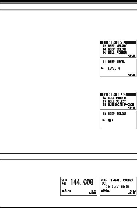
ADVANCED OPERATION
ADJUSTING THE KEYPAD BEEPER VOLUME LEVEL
A keypad beeper provides useful audible feed back whenever a key button is pressed. The keypad beeper level changes according to the receiver audio volume level setting. However, you may adjust the volume balance between the receiving audio and keypad beeper using Set Mode Item 11: BEEP LEVEL.
1.Press and hold the  key for one second to enter the Set Mode.
2.Rotate the DIAL knob to select Set Mode Item 11: BEEP 
LEVEL.
3. Press the  key briefly to enable selection of this Set Mode Item.
4. Rotate the DIAL knob to select the desired level.
5.When you have made your choice, press the PTT switch to save the new setting and return to normal operation.
Additionally, if you want to turn the beep off:
1.Press and hold the  key for one second to enter the Set Mode.
2.Rotate the DIAL knob to select Set Mode Item 13: BEEP 
SELECT.
3. Press the  key briefly to enable selection of this Set Mode Item.
4. Rotate the DIAL knob to change the setting to “OFF”.
5.When you have made your choice, press the PTT switch to save the new setting and return to normal operation.
6.If you wish to re-enable the Beeper, just repeat the above  procedure, rotating the DIAL knob to select “KEY” or “KEY & SCAN” in step “4” above.
KEY: The beeper sounds when you press any key.
KEY & SCAN: The beeper sounds when you press a key or when the scanner stops.
SETTING THE FREQUENCY DISPLAY IMAGE SIZE
When operating in “Mono” band, pressing the  or
or  key, causes the LCD to “toggle” between display of double-size characters and large characters. However, this feature does not work during Dual Receive operation, as two frequencies are displayed in that instance.

DOUBLE-SIZE CHARACTERS LARGE CHARACTERS
VX-8DR OPERATING MANUAL |
27 |
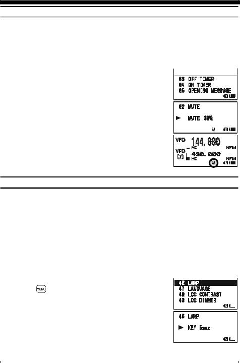
ADVANCED OPERATION
AUDIO MUTING
The Audio Mute feature is useful in situations where it would be helpful to reduce the audio level of the “Receive Only” band (Small character display) whenever you receive a signal on the “Main” band (Large character display) during Dual Receive operation.
To activate the Audio Mute feature:
1.Press and hold the  key for one second to enter the Set Mode.
2.Rotate the DIAL knob to select Set Mode Item 62: MUTE. 
3. Press the  key briefly to enable selection of this Set Mode Item.
4. Rotate the DIAL knob to select the desired muting level (MUTE 30%, MUTE 50%, MUTE 100%, or OFF).
5. When you have made your choice, press the PTT switch to save the new setting and return to normal operation.
When the Audio Mute feature is activated, the “ ” icon will
  appear on the display, and the “
 ” icon blinks while muting the


“Receive Only” band audio.
KEYPAD/LCD ILLUMINATION
Your VX-8DR includes a reddish illumination lamp which aids in nighttime operation. The red illumination yields clear viewing of the display in a dark environment, with minimal degradation of your night vision. Three options for activating the lamp are provided:
KEY 2sec - KEY 10sec: Illuminates the Keypad/LCD for the selected illumination
|
time when any key is pressed. |
CONTINUOUS: |
Illuminates the Keypad/LCD continuously. |
OFF: |
Disables the Keypad/LCD lamp. |
Here is the procedure for setting up the Lamp mode:
1.Press and hold the  key for one second to enter the Set Mode.
2.Rotate the DIAL knob to select Set Mode Item 46: LAMP. 
3. |
Press the |
key briefly to enable selection of this Set Mode |
|
||
|
Item. |
|
|
|
|
4. |
Rotate the DIAL knob to select one of the three modes de- |
|
|
|
|
|
|
||||
|
|
||||
|
scribed above. |
|
|||
5.When you have made your choice, press the PTT switch to save the new setting and return to normal operation.
|
|
|
|
28 |
VX-8DR OPERATING MANUAL |
||
 Loading...