

Page 1
Motors | Automation | Energy | Transmission & Distribution | Coatings
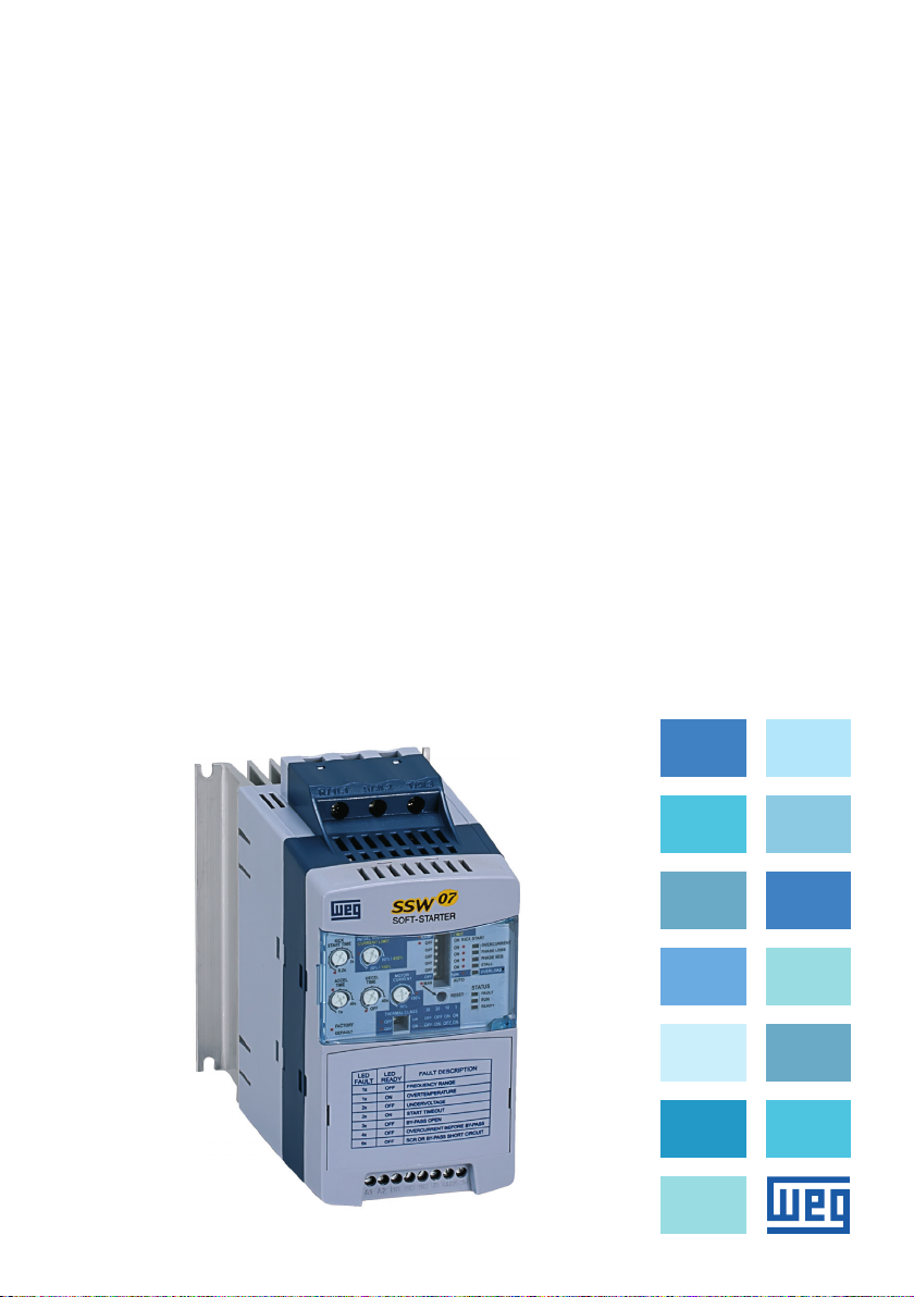
Soft-Starter
Arrancador Suave
Soft-Starter
SSW-07
User's Manual
Manual del Usuario
Manual do Usuário
Page 2

SOFT-STARTER
USER’S MANUAL
MANUAL DEL
USUARIO DEL
ARRANCADOR
SUAVE
English
Español
MANUAL DO
USUÁRIO DA
SOFT-STARTER
Series: SSW-07
Document: 0899.5832 / 10
English - Español - Português
Português
07/2012
Page 3
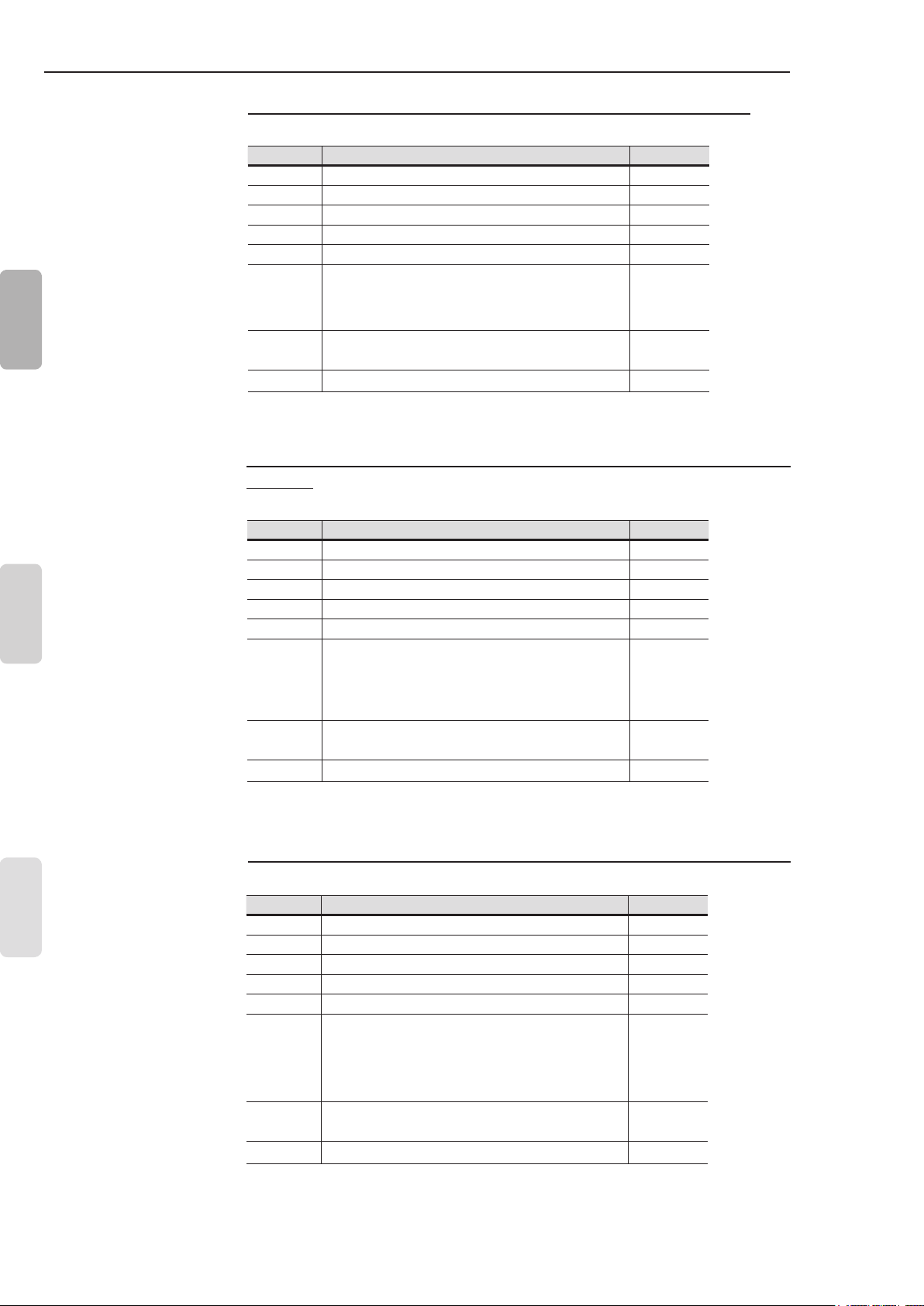
Summary of revisions / Sumario de las revisiones / Sumário das revisões
The information below describes the revisions in this manual.
Revision Description Chapter
1 First Edition 2 General Revision 3 General Revision 4 Size 4 Included -
5 and 6 Table 3.1 and 8.2 corrected 3 and 8
English
Revision after the Size 4 UL certication.
7
Changed: item 3.2.3; 3.2.4.1; 3.2.4.2; 3.2.7;
4.8; 5.2; E77 in the table 6.1; table 8.1
8
9 General Revision -
Included new functions of
software version V1.4x
3, 4, 5, 6
and 8
3,4
and 5
La información abajo describe las revisiones ocurridas en este
manual.
Español
Português
Revisión Descripción Capítulo
1 Primer Edición 2 Revisión General 3 Revisión General 4 Inclusión Mecánica 4 -
5 y 6 Correción de las tablas 3.1 y 8.2 3 y 8
Corrección luego de la certicación UL de la
Mecánica 4. Modicado: ítem 3.2.3; 3.2.4.1;
7
8
9 Revisión General -
3.2.4.2; 3.2.7; 4.8; 5.2; E77 en la tabla 6.1;
tabla 8.1
Inclusión de las nuevas funciones de la
version de software V1.4x
3, 4, 5, 6
y 8
3, 4 y 5
A informação abaixo descreve as revisões ocorridas neste manual.
Revisão Descrição Capítulo
1 Primeira Edição 2 Revisão Geral 3 Revisão Geral 4 Inclusão da mecânica 4 -
5 e 6 Correções das tabelas 3.1 e 8.2 3 e 8
Correção depois da certicação UL da
7
8
9 Revisão Geral -
Mecânica 4. Alterado: item 3.2.3; 3.2.4.1;
3.2.4.2; 3.2.7; 4.8; 5.2; E77 na tabela 6.1;
tabela 8.1
Inclusão das novas funções da versão
de software V1.4x
3, 4, 5,
6 e 8
3, 4 e 5
Page 4

Summary
CHAPTER 1
Safety Instructions
1.1 Safety Notices in the Manual ................................................5
1.2 Safety Notices on the Product ..............................................5
1.3 Preliminary Recommendations .............................................5
CHAPTER 2
General Information
2.1 About this Manual ................................................................7
2.2 About the Soft-Starter SSW-07 ............................................7
2.3 Soft-Starter SSW-07 Identication Plate ............................8
2.4 Receiving and Storage .......................................................11
CHAPTER 3
Installation and Connection
3.1 Mechanical Installation .......................................................12
3.1.1 Environmental Conditions ............................................12
3.1.2 Soft-Starter SSW-07 Dimensions ................................12
3.1.3 Mounting Specications ...............................................13
3.1.3.1 Mounting Inside a Panel .....................................14
3.1.3.2 Mounting on Surface ..........................................15
3.2 Electrical Installation ...........................................................15
3.2.1 Power Terminals ...........................................................16
3.2.2 Location of the Grounding, Control and Power
Connections ..................................................................17
3.2.3 Recommended Power and Grounding Cables ............18
3.2.4 Power Supply Connection to the Soft-Starter SSW-07 18
3.2.4.1 Power Supply Capacity .......................................19
3.2.4.2 Recommended Fuses .........................................19
3.2.4.3 Recommended Contactors .................................20
3.2.5 Soft-Starter SSW-07 Connection to the Motor .............20
3.2.5.1 Standard Three-Wire Connection .......................21
3.2.6 Grounding Connections ...............................................21
3.2.7 Control and Signal Connections ...................................22
3.3 Recommended Set-ups ......................................................23
3.3.1 Recommended Set-up with Command via Two-wire
Digital Inputs and Isolation Contactor ..........................24
3.3.2 Recommended Set-up with Command via Three-wire
Digital Inputs and Circuit-Breaker ................................24
3.3.3 Recommended Set-up with Command via Two-wire
Digital Inputs and Direction of Rotation .......................25
3.3.4 Recommended Set-up with Command via Two-wires
Digital Inputs and DC-Braking .....................................26
3.3.5 Symbols .......................................................................27
English
Page 5

Summary
English
CHAPTER 4
Setting the SSW-07
4.1 Control Type Setting ...........................................................28
4.2 Kick Start ............................................................................29
4.3 Initial Voltage Setting ..........................................................29
4.4 Current Limit Setting ...........................................................30
4.5 Acceleration Ramp Time Setting ........................................31
4.6 Deceleration Ramp Time Setting ........................................31
4.7 Motor Current Setting .........................................................32
4.8 Motor Electronic Overload Protection ................................33
4.9 Reset ..................................................................................36
4.10 DI2 Digital Input Setting ....................................................36
4.11 Output Relay Operation ....................................................37
4.12 Relay Output RL1 Programming ......................................37
CHAPTER 5
Programming Information and Suggestions
5.1 Applications and Programming ...........................................38
5.1.1 Voltage Ramp Starting .................................................39
5.1.2 Current Limit Starting ...................................................40
5.1.3 Starting with Pump Control (P202 = 2) ........................40
5.1.4 Programming the control type in pump control ............42
5.2 Protections and Programming ............................................43
5.2.1 Suggestion on How to Program the Thermal Class .....43
5.2.2 Service Factor ..............................................................45
CHAPTER 6
Solution and Troubleshooting
6.1 Faults and Possible Causes ...............................................47
6.2 Troubleshooting ..................................................................50
6.3 Preventive Maintenance .....................................................51
CHAPTER 7
Options and Accessories
7.1 IP20 Kit ...............................................................................52
CHAPTER 8
Technical Characteristics
8.1 Nominal Powers and Currents According to UL508 ...........53
8.2 Nominal Powers and Currents for Standard IP55,
IV Pole Weg Motor .............................................................53
8.3 Power Data .........................................................................54
8.4 Electronics and Programming Data ....................................54
Page 6
CHAPTER 1
SAFETY INSTRUCTIONS
This Manual contains the necessary information for the correct use
of the Soft-Starter SSW-07.
It was written to be used by qualied personnel with suitable training
or technical qualications to operate this type of equipment.
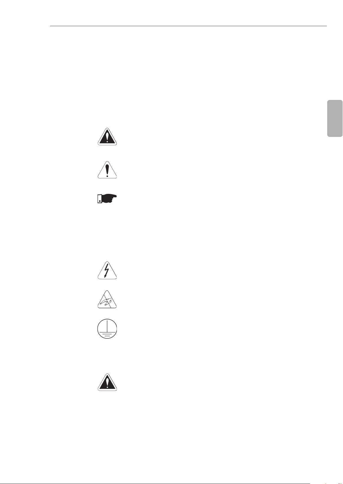
1.1 SAFETY NOTICES IN THE MANUAL
1.2 SAFETY NOTICES ON THE PRODUCT
The following safety notices will be used in the text.
DANGER!
The nonobservance of the procedures recommended in this warning
can lead to death, serious injuries and considerable material damage.
ATTENTION!
Failure to observe the recommended procedures in this notice may
lead to material damage.
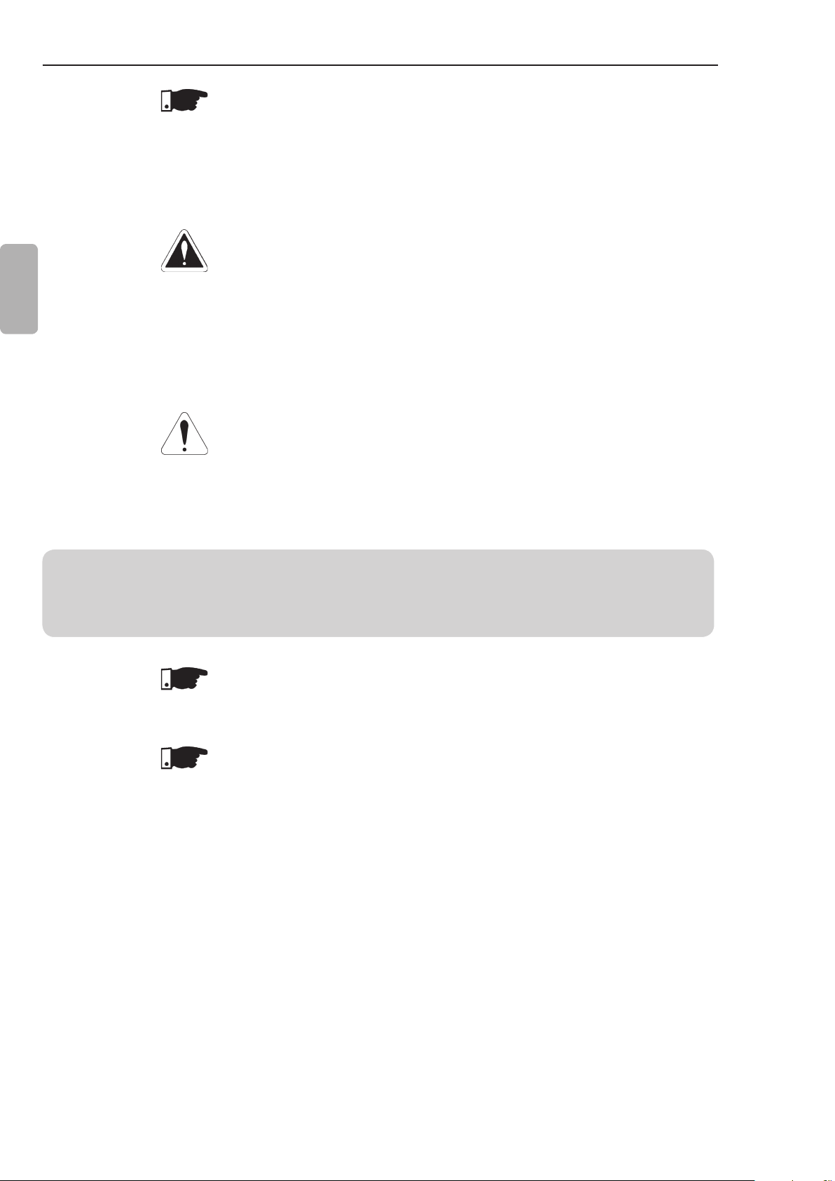
NOTE!
The text intents to supply important information for the correct
understanding and good operation of the product.
The following symbols may be attached to the product as a safety
notice.
English
1.3 PRELIMINARY RECOMMENDATIONS
High Voltages.
Components are sensitive to electrostatic discharge.
Do not touch them.
Mandatory connection to ground protection (PE).
DANGER!
Only personnel with suitable qualication and familiar with the
Soft-Starter SSW-07 and associated equipment should plan or
implement the installation, start-up, operation and maintenance of
this equipment.
These personnel must follow all safety instructions in this manual
and/ or dened by local regulations.
Failure to follow these safety instructions may result in personnel
injury and/or equipment damage.
5
Page 7
CHAPTER 1 - SAFETY INSTRUCTIONS
NOTE!
In this Manual, qualied personnel are those trained to:
1. Install, ground, power-up, and operate the Soft-Starter SSW-07
according to this manual and the required safety procedures;
2. Use protection equipment according to established regulations;
3. Give First Aid.
DANGER!
Always disconnect the general power supply before touching any
electrical component associated to the Soft-Starter SSW-07.
English
High voltage may be present even after the power supply is
disconnected. Wait at least 3 minutes for the total discharge of the
capacitors.
Always connect the equipment’s heatsink to the protection ground
(PE), at the proper connection point.
ATTENTION!
All electronic boards have components that are sensitive to
electrostatic discharges. Do not touch these components or
connectors directly.
If necessary, rst touch the grounded metallic heatsink or use a
suitable grounded wrist strap.
Do not apply any high voltage test on the Soft-Starter SSW-07!
If necessary, contact the manufacturer.
NOTE!
Soft-Starters SSW-07 may interfere with other electronic equipment.
Follow the measures in Chapter 3 to reduce these effects.
NOTE!
Read this manual completely before installing or operating the
Soft-Starter SSW-07.
6
Page 8
GENERAL INFORMATION
Tampa para
Trifásica
Opcionais Plug-In
Ajustes e Habilitar as
Proteções
DIP Swith para
LED's para Indicação
Entrada de Alimentação
de Status da SSW-07
Saída para Motor
Saida a Relé
(13,14/23 e 24)
CHAPTER 2
2.1 ABOUT THIS MANUAL
2.2 ABOUT THE
SOFT-STARTER
SSW-07
This manual presents the Soft-Starter installation, how to start it up,
its main technical characteristics and how to identify and correct the
most common problems. The manuals listed next must be consulted
in order to get more information regarding the functions, accessories
and working conditions:
Programming Manual, with a detailed description of the
parameters and its functions;
RS232 / RS485 Communication Manual.
DeviceNet Communication Manual.
These manuals are supplied in electronic format on the CD-ROM
that accompanies the Soft-Starter, or can be obtained at WEG’s
web site: http://www.weg.net.
The Soft-Starter SSW-07 is a high performance product that permits
the start control of the three phase AC induction motors. Thus, it
prevents mechanical shocks on the load and current peaks in the
supply line.
Three-phase
Power Supply
English
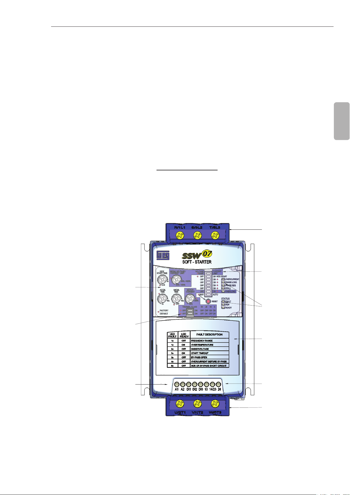
Trimpots to adjust
DIP switch to adjust
the Thermal Class
Electronic Power Supply
(A1 and A2)/
Start/Stop Command
of the Motor (D1) and
Reset (DI2 and DI3)
Figure 2.1 - Frontal view of the SSW-07
DIP Switch for
Soft-Starter adjustment
and protection enabling
Status Indication LEDs
of the SSW-07
Lid for optional Plug-in
Modules
Relay Output
(13, 14/23 and 24)
Motor Output
7
Page 9
CHAPTER 2 - GENERAL INFORMATION
English
Three-Phase
Power Supply
R S
U
V W
Three-Phase Motor
Programmable
Digital Inputs
Dl1
Dl2
Dl3
T
Control
Power Supply
A1
A2
3 x
Digital Signal
2 x
Processor
DSP
PE
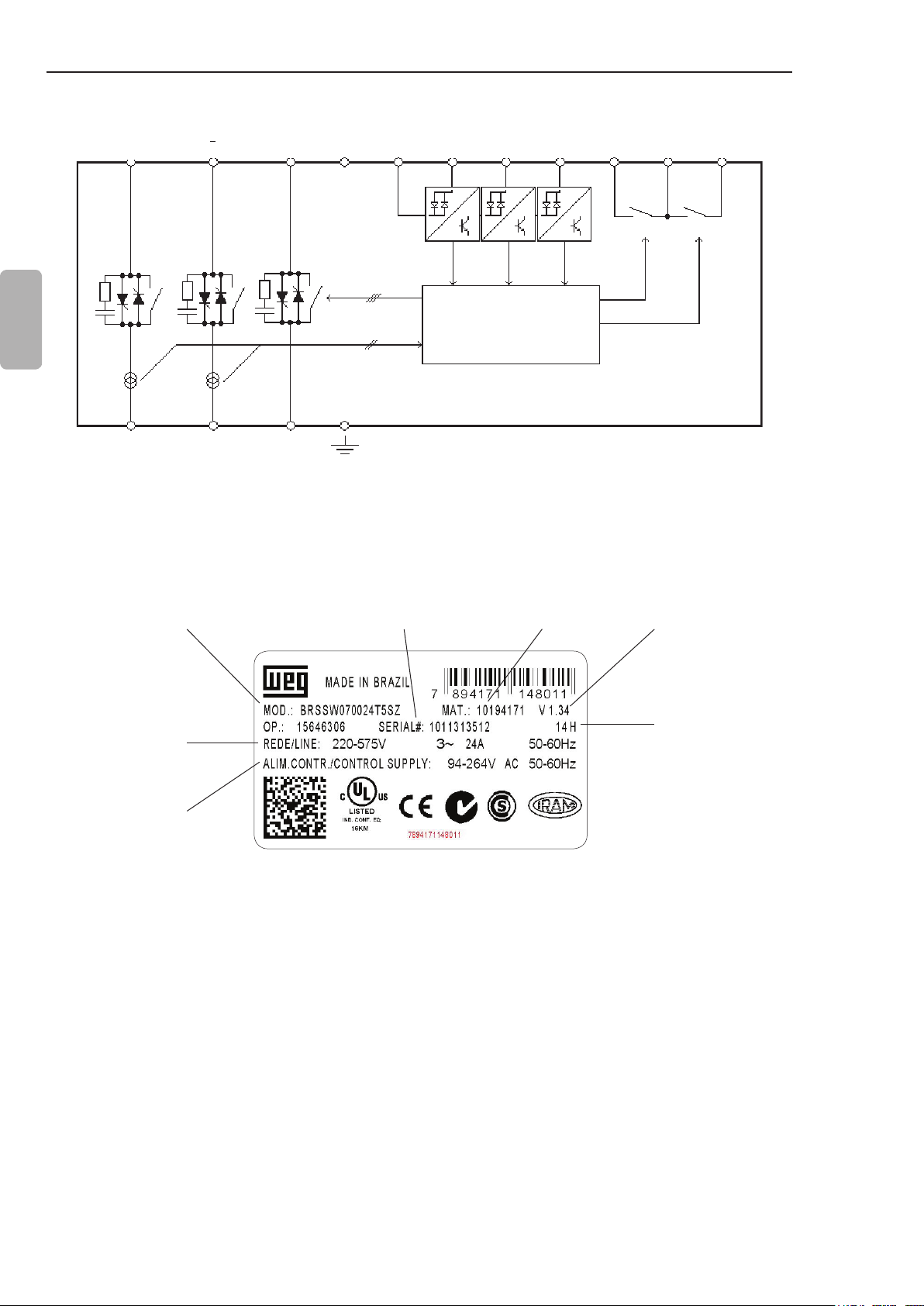
Figure 2.2 - Soft-Starter SSW-07 block diagram
Programmable Digital
Outputs
13
14/23 24
RL1
RL2
2.3 SOFT-STARTER SSW-07 IDENTIFICATION PLATE
WEG Stock
SSW-07 Model
Input Data (Voltage,
Number of Phases,
Current and Frequency)
Control Power Supply
Data (Voltage, Frequency)
Serial Number
Figure 2.3 - Soft-Starter SSW-07 identication plate
Item Number
Software
Version
Manufacturing date
(14 corresponds to
week and H to year)
8
Page 10
CHAPTER 2 - GENERAL INFORMATION
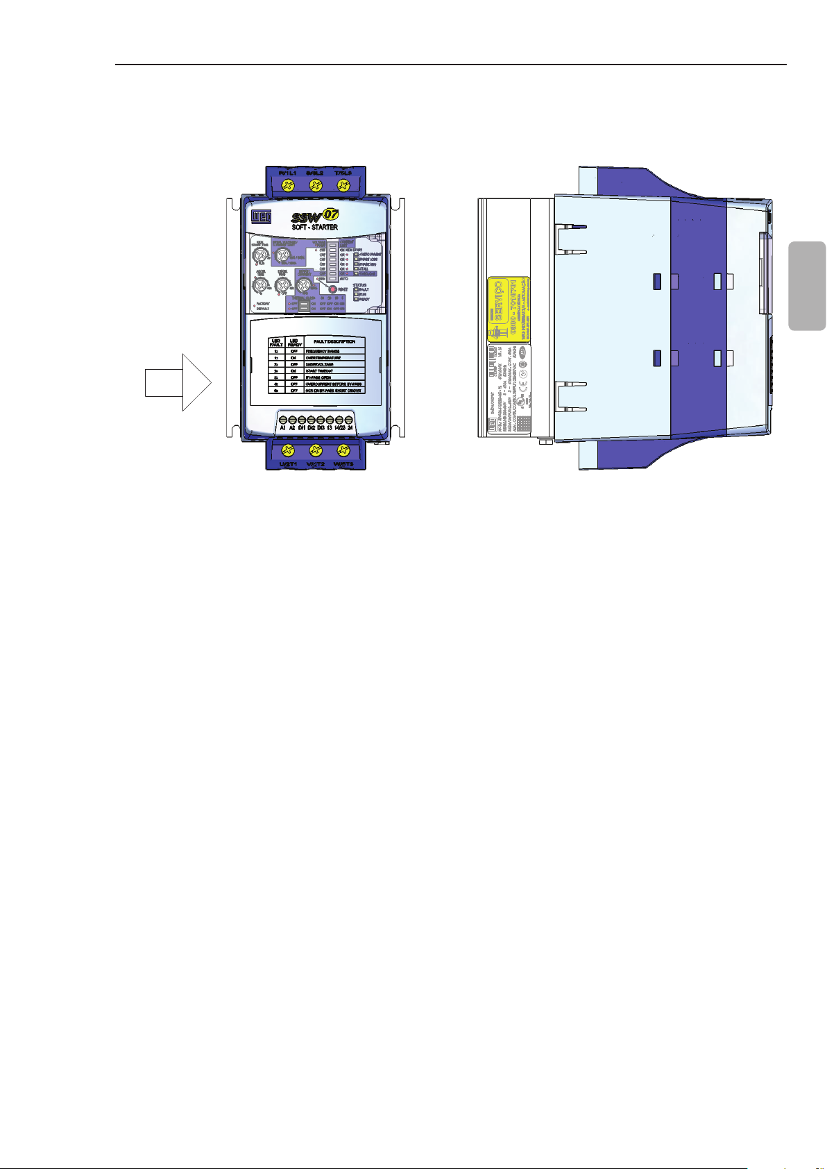
VISTA FRONTAL
VISTA DE X
Position of the Identication Plate on the Soft-Starter SSW-07:
FRONTAL VIEW X VIEW
English
X
Figure 2.4 - Location of the labels
9
Page 11
CHAPTER 2 - GENERAL INFORMATION
End of
Code
Special
Software
Blank =
Standard
S1 = Special
Software
English
Special
Hardware
Blank =
Degree of
Protection
Blank =
S = Standard
O = with
220-575 Vac Optional:
(2)
Standard
H1 = Electronics
supply: 110 to
130 Vac
H2 = Electronics
(1)
Standard
IP=IP20
Optional
(2)
supply: 208 to
240 Vac
10
HOW TO SPECIFY THE SSW-07 MODEL:
Three-
Phase
SSW-07
Nominal Current
WEG Soft-
Starter
EX SSW-07 0017 T 5 S _ _ _ _ _ _ Z
Market
Power
Supply
0017 = 17 A
0024 = 24 A
0030 = 30 A
Series
SSW-07
BR = Brazil
EX = Export
0045 = 45 A
0061 = 61 A
0085 = 85 A
0130 = 130 A
0171 = 171 A
0200 = 200 A
0255 = 255 A
0312 = 312 A
0365 = 365 A
0412 = 412 A
(1) Only for models 130 A to 412 A.
(2) Only for the 255 A to 412 A models.
NOTE!
The option eld (S or O) denes if the Soft-Starter SSW-07 will be a standard version or if it will include any optional. If standard, the
code ends here.
Always put the letter Z at the end. For example:
EXSSW070017T5SZ = Standard Soft-Starter SSW-07 with 17 A and 220 V to 575 V to three-phase input with the User’s Guide in
English, Spanish and Portuguese.
If there is any optional, the elds must be lled out in the correct sequence until the code is completed with the letter Z.
The standard product as dened by this code is described as:
Degree of Protection: IP20 from 17 A to 85 A and IP00 from 130 A to 412 A.
Page 12
CHAPTER 2 - GENERAL INFORMATION
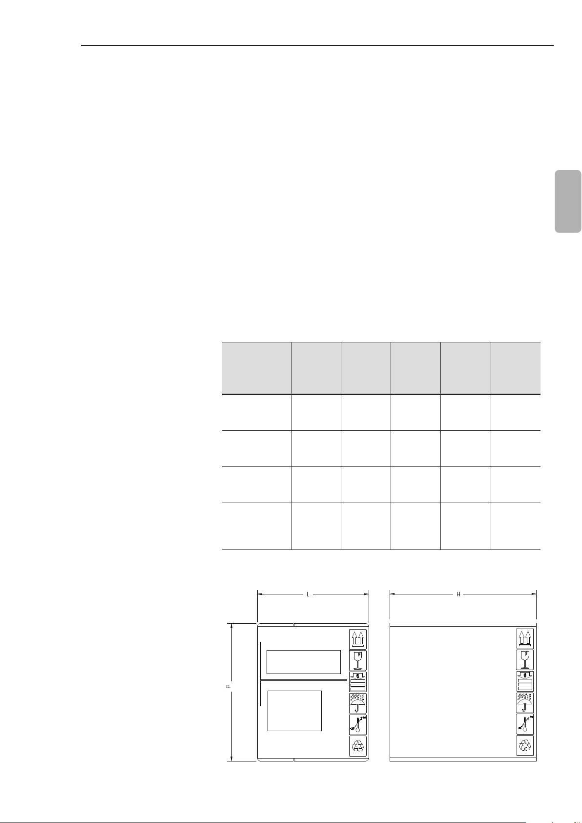
2.4 RECEIVING AND STORAGE
The Soft-Starter SSW-07 is supplied in a cardboard box. On the
outside of the package there is an identication plate which is
identical to the one placed on the Soft-Starter SSW-07.
To open the package:
1- Put it on a table;
2- Open the package;
3- Take out the Soft-Starter.
Check if:
The Identication plate of the Soft-Starter SSW-07 matches the
model purchased:
Damage has occurred during transport. If so, contact the carrier
immediately.
If the Soft-Starter SSW-07 is not installed immediately, store it in
its package in a clean and dry place with temperature between
-25 °C (-13 °F) and 65 °C (149 °F). 1 hour at -40 °C (-40 °F) is
permitted.
English
SSW-07
Model
17 A
24 A
30 A
45 A
61 A
85 A
130 A
171 A
200 A
255 A
312 A
365 A
412 A
Height
H
mm
(in)
221
(8.70)
260
(10.24)
356
(14.02)
415
(16.34)
Table 2.1 - Dimensions of the package in mm (in)
Width
L
mm
(in)
180
(7.09)
198
(7.80)
273
(10.75)
265
(10.43)
Depth
P
mm
(in)
145
(5.71)
245
(9.65)
295
(11.61)
320
(12.6)
Volume
3
cm
(in3)
5768
(352.2)
12613
(770.8)
28670
(1750)
35192
(2147)
Weight
kg
(lb)
1.65
(3.64)
3.82
(8.42)
8.36
(18.43)
12.8
(28.2)
Figure 2.5 - Dimensions of the package
11
Page 13
C
A
B
P
L
3.1 MECHANICAL INSTALLATION
CHAPTER 3
INSTALLATION AND CONNECTION
This chapter describes the procedures for the electrical and
mechanical installation of the Soft-Starter SSW-07. The guidelines
and suggestions must be followed for the correct operation of the
Soft-Starter SSW-07.
3.1.1 Environmental
English
Conditions
The location of the Soft-Starters SSW-07 is an important factor to
assure the correct operation and high product reliability.
Avoid:
Direct exposure to sunlight, rain, high moisture and sea air ;
Exposure to explosive or corrosive gases and liquids;
Exposure to excessive vibration, dust or any metallic and/or oil
particles in the air.
Allowed Environmental Conditions:
Surrounding air Temperature: 0 ºC to 55 ºC (32 ºF to 131 ºF) -
nominal conditions.
Relative air moisture: 5 % to 90 %, with no-condensation.
Maximum altitude: 1,000 m (3,300 ft) above sea level - nominal
conditions.
From, 1,000 m to 4,000 m (3,300 ft to 13,200 ft) above sea level -
current reduction of 1 % for each 100 m (330 ft) above 1,000 m
(3,300 ft).
From 2000 m to 4000 m (6,600 ft to 13,200 ft) above sea level -
voltage reduction of 1.1 % for each 100m (330 ft) above 2,000 m
(6,600 ft).
Pollution degree: 2 (according to the UL508).
Normally, only non conductive pollution. Condensation must not
cause conduction in the particles in the air.
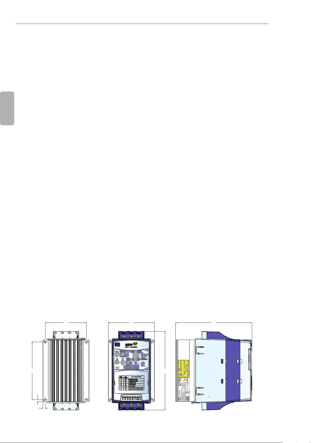
3.1.2 Soft-Starter SSW-07 Dimensions
B
D
D
C
12
The external dimensions and mounting holes are shown in gure
3.1 and table 3.1 below.
A
Figure 3.1 - SSW-07 dimensions
L
H
H
P
Page 14
CHAPTER 3 - INSTALLATION AND CONNECTION
Height
SSW-07
Model
17 A
24 A
30 A
45 A
61 A
85 A
130 A
171 A
200 A
255 A
312 A
365 A
412 A
H
mm
(in)
162
(6.38)95(3.74)
208
(8.19)
276
(10.9)
331
(13.0)
* IP20 with optional.
3.1.3 Mounting
Specications
Width
L
mm
(in)
144
(5.67)
223
(8.78)
227
(8.94)
Depth
P
mm
(in)
157
(6.18)85(3.35)
203
(7.99)
220
(8.66)
242
(9.53)
A
mm
(in)
132
(5.2)
208
(8.19)
200
(7.87)
B
mm
(in)
120
(4.72)5(0.20)4(0.16) M4
148
(5.83)6(0.24)
210
(8.27)
280
(11.0)15(0.59)9(0.35)
C
mm
(in)
7.5
(0.3)
D
Mounting
mm
(in)
3.4
(0.13) M4
5
(0.2) M5
Screw
M8
Weight
kg
(lb)
1.3
(2.9) IP20
3.3
(7.28) IP20
7.6
(16.8)
11.5
(25.4)
Table 3.1 - Installation data with dimensions in mm (in)
To install the Soft-Starter SSW-07 leave at least the free spaces
surrounding the Soft-Starter as in gure 3.2 below. The dimensions
of these free spaces are described in table 3.2.
Degree
of
Protection
IP00 *
English
IP00 *
SSW-07 Model
17 A
24 A
30 A
45 A
61 A
85 A
130 A
171 A
200 A
A
mm
(in)
50
(2)
80
(3.2)
100
(4)
B
mm
(in)
50
(2)
80
(3.2)
100
(4)
C
mm
(in)
30
(1.2)
30
(1.2)
30
(1.2)
255 A
312 A
365 A
150
(6)
150
(6)
30
(1.2)
412 A
Table 3.2 - Recommended free spaces
Install the Soft-Starter SSW-07 in the vertical position according to
the following recommendations:
1) Install on a reasonably at surface;
2) Do not put heat sensitive components immediately above the
Soft-Starter SSW-07.
ATTENTION!
If a Soft-Starter SSW-07 is installed on top of another use the
minimum distance A + B and diverge from the top Soft-Starter the
hot air that comes from the one beneath it.
13
Page 15

CHAPTER 3 - INSTALLATION AND CONNECTION
ATTENTION!
Independent conduits or cable trays must be planned for physic
separation of signal, control and power cables. (Refer to item 3.2
Electrical Installation).
A
A
English
SAIDA
Air Flow
FLUXO DE AR
Outlet
C
C
3.1.3.1 Mounting Inside a Panel
SSW-07
Model
130 A 12 117 129
171 A 12 154 166
200 A 12 180 192
255 A 12 230 242
312 A 12 281 293
365 A 12 329 341
412 A 12 371 383
Air Flow
B
B
Figure 3.2 - Free spaces for ventilation
ENTRADA
FLUXO DE AR
Inlet
For Soft-Starters SSW-07 installed in panels or closed metallic
boxes exhaustion/cooling is required so the temperature does not
exceed the maximum allowed. Refer to dissipated nominal power
in table 3.3.
Average Power
Dissipated Power
in the electronics
(W)
17 A 12 15.3 27.3
24 A 12 21.6 33.6
30 A 12 27 39
45 A 12 41 53
61 A 12 55 67
85 A 12 77 89
dissipated
10 starts/h
3 x In @ 30 s
(W)
Total Average Power
dissipated
10 starts/h
3 x In @ 30 s
(W)
14
Table 3.3 - Dissipated power for ventilator panel dimensioning
Page 16
CHAPTER 3 - INSTALLATION AND CONNECTION
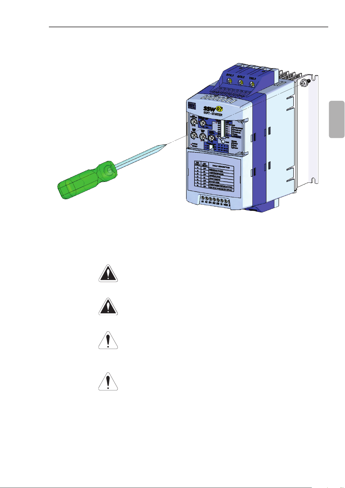
3.1.3.2 Mounting on Surface
Figure 3.3 shows the installation of the Soft-Starter SSW-07 on the
surface of a mounting plate.
English
Figure 3.3 - Installation procedures of the Soft-Starter SSW-07 on a surface
3.2 ELECTRICAL
INSTALLATION
DANGER!
The Soft-Starter SSW-07 cannot be used as an emergency stop
device.
DANGER!
Be sure that the AC input power is disconnected before making any
terminal connection.
ATTENTION!
The information below may be used as a guide to achieve a proper
installation. Follow also the applicable local standards for electrical
installations.
ATTENTION!
If a power isolating contactor or circuit breaker with minimum voltage
coil is not used at the rst power on, then power up the electronics
rst, adjust the trimpots that are necessary to put the SSW-07 into
operation and only after this energize the power section.
15
Page 17
CHAPTER 3 - INSTALLATION AND CONNECTION
Circuit-breaker
T
S
R
Line
English
Fuses
R/1L1 S/3L2 T/5L3
3.2.1 Power Terminals
U/2T1 V/4T2 W/6T3 PE
Figure 3.4 - Standard power/grounding connections
PE
PE
The power terminal blocks vary in size and conguration, depending
on the SSW-07 soft-starter model, as can be observed at the gures
3.5 and 3.6.
Terminals:
R / 1L1, S / 3L2 and T / 5L3: AC supply line.
U / 2T1, V / 4T2 and W / 6T3: Motor connection.
16
Page 18
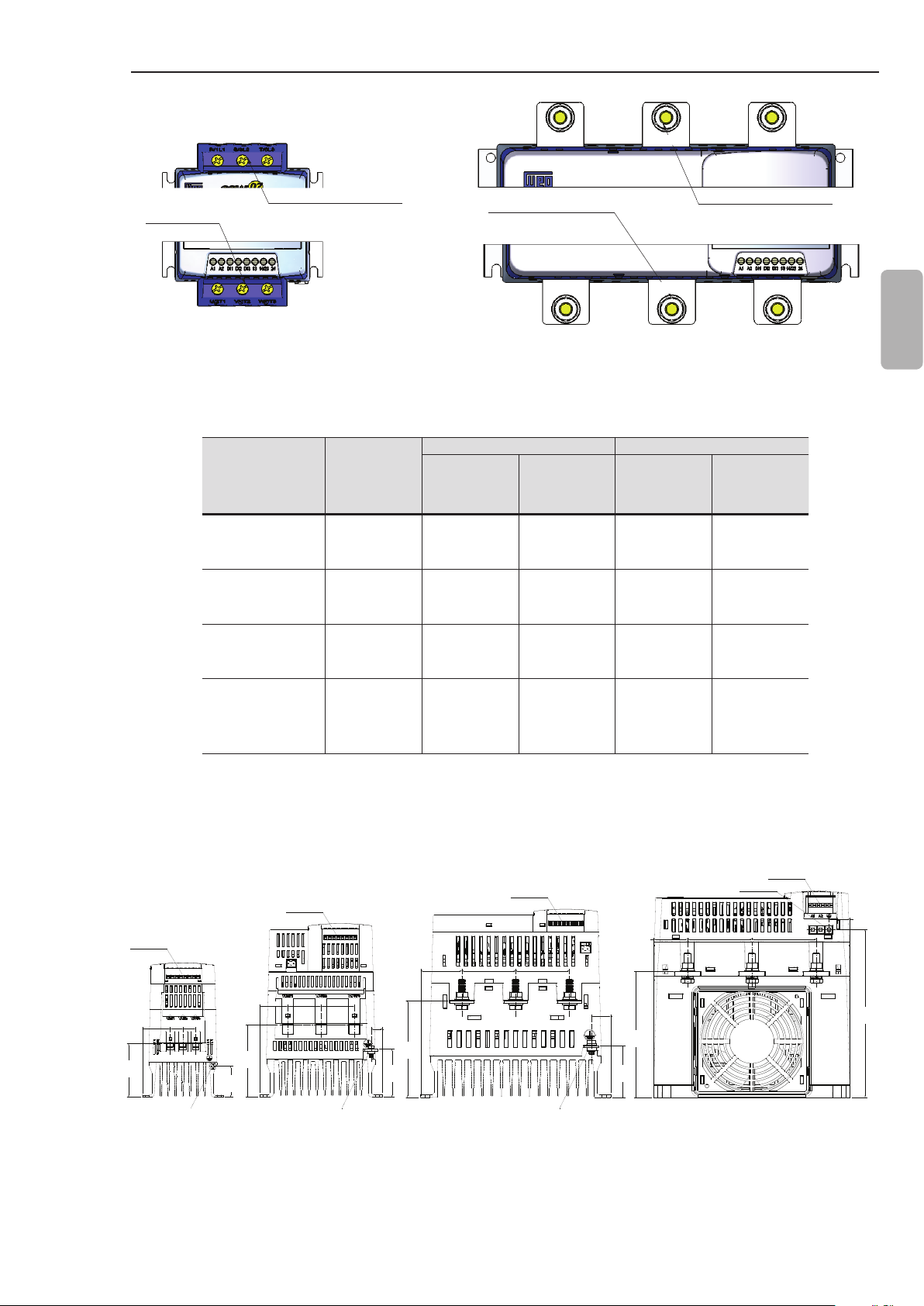
CHAPTER 3 - INSTALLATION AND CONNECTION
R/1L1 S/3L2 T/5L3
Output Power
BORNE DE SAIDA
POTENCIA
Terminal
Models 17 A to 85 A Models 130 A to 412 A
Input
BORNE DE ENTRADA
Power Terminal
POTENCIA
SSW-07
Model
17 A
24 A
30 A
45 A
61 A
85 A
130 A
171 A
200 A
255 A
312 A
365 A
412 A
Figure 3.5 - Power terminals
Enclosure
Size
Screw/
Terminal
Size 01 Terminal
Size 02 Terminal
Size 03
Size 04
M8
(5/16”)
M10
(3/8”)
R/1L1
Output
BORNE DE SAIDA
POTENCIA
Power Terminal
U/2T1
S/3L2
V/4T2
Input
BORNE DE ENTRADA
POTENCIA
Power Terminal
Line / Motor Grounding
Torque
Nm
Screw
(in lb)
3
(27)
5.5
(49)
19
(168)
37
(328)
M4
(5/32”)
M5
(3/16”)
M6
(1/4”)
Terminal
T/5L3
W/6T3
English
Torque
Nm
(in lb)
4.5
(40)
6
(53)
8.3
(73)
0.5
(4.5)
Table 3.4 - Maximum torque for power connection
3.2.2 Location of the Grounding, Control and Power Connections
Control
Control
CONTROLE
Control
CONTROLE
48.2
(1.90)
39.0
(1.54)
ATERRAMENTO
39.0
(1.54)
13.3
(0.52)
114
(4.48)
56.3
(2.22)
62.8
(2.48)
32.7
(1.29)
ATERRAMENTO
33.0
36.3
84,8
(3.34)
(1.30)
14.8
14.8
(0.59)
(0.59)
(1.43)
Grounding Grounding Grounding
Dimensions in mm (in).
Figure 3.6 - Location of the grounding, control and power connections
CONTROLE
63.0
(2.48)
(2.48)
ATERRAMENTO
63.0
22.7
(0.89)
60.5
(2.38)
39.7
(1.56)
148
(5.81)
Grounding
ATERRAMENTO
75.5
(2.97)
Control
CONTROLE
75.5
(2.97)
25.1
(0.99)
197
(7.75)
17
Page 19
CHAPTER 3 - INSTALLATION AND CONNECTION
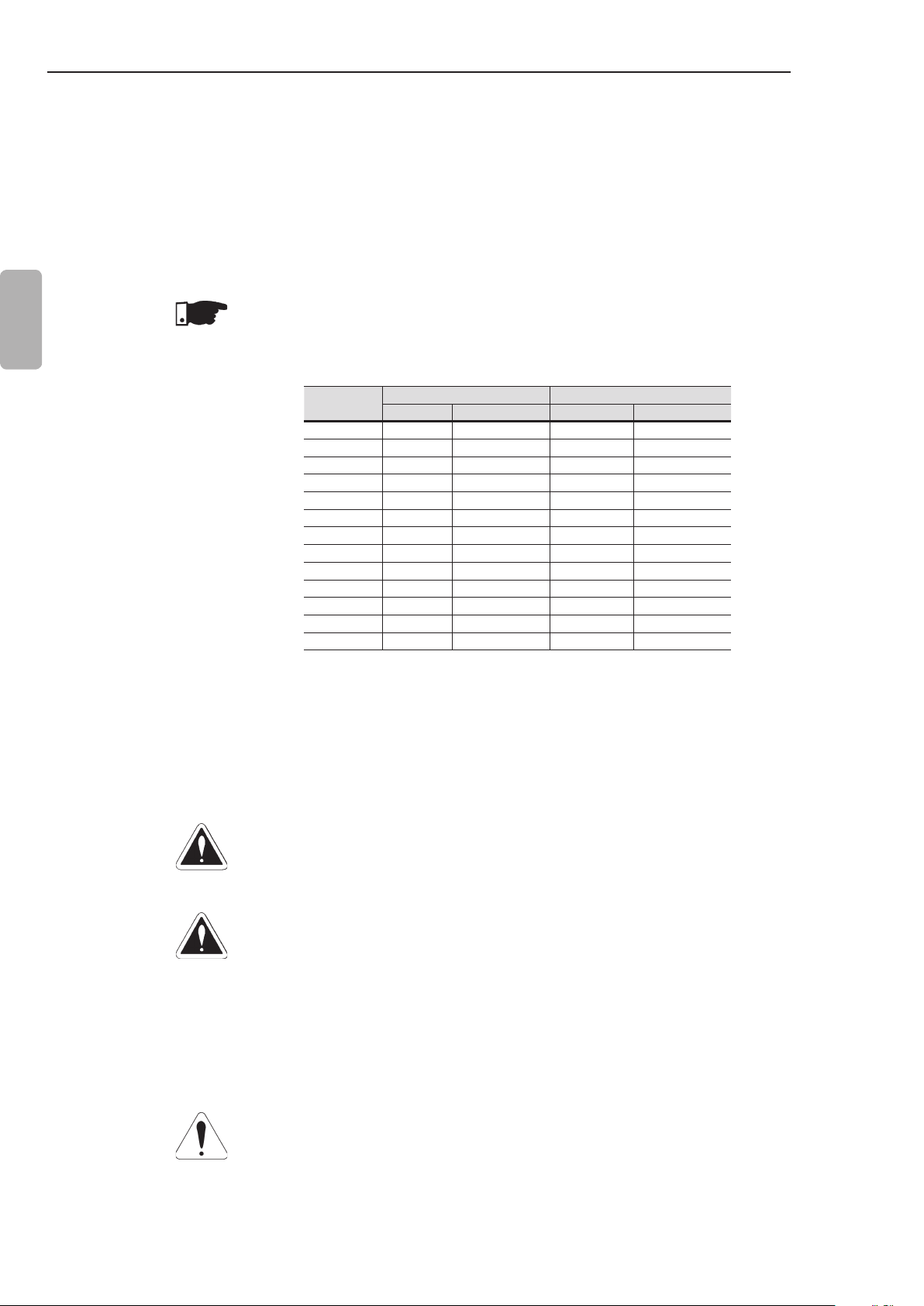
3.2.3 Recommended Power and Grounding Cables
English
The described specications in table 3.5 are valid only for the
following conditions:
Copper wires for 70 ºC (158 ºF) with PVC insulation for ambient
temperature of 40 ºC (104 ºF), installed in perforated and not
agglomerated conduits.
Naked or silver coated copper busbars with round edges with 1
mm radius with ambient temperature of 40 ºC (104 ºF) and bus
temperature of 80 °C (176 °F).
NOTE!
For correct cable dimensioning, consider the installation condition
and the maximum permitted line voltage drop.
SSW-07
Model
17 A 4 12 4 12
24 A 6 10 6 10
30 A 6 10 6 10
45 A 10 8 6 10
61 A 16 6 10 8
85 A 25 4 10 8
130 A 50 1 25 4
171 A 70 2/0 35 2
200 A 95 3/0 50 1
255 A 120 250 kcmil 2.5 14
312 A 185 350 kcmil 2.5 14
365 A 240 500 kcmil 2.5 14
412 A 300 600 kcmil 2.5 14
Power Cable Grounding Cable
2
) AWG (mm2) AWG
(mm
3.2.4 Power Supply Connection to the Soft-Starter SSW-07
18
Table 3.5 - Minimum cable gauge specication
DANGER!
The AC input must be compatible with the voltage range of the
Soft-Starter SSW-07.
DANGER!
Provide a power supply disconnecting switch for the Soft-Starter
SSW-07. This disconnecting switch must disconnect the AC input
voltage to the Soft-Starter SSW-07 whenever necessary (for
example: during maintenance services).
If a disconnected switch or a contactor is inserted in the motor supply
line never operate these devices with the motor running or when
the Soft-Starter SSW-07 is enabled.
ATTENTION!
The overvoltage control in the line that feeds the soft-starter must
be done using overvoltage suppressors with a clamping voltage of
680 Vac (phase-to-phase connection) and an energy absorption
capability of 40 joules (17 A to 200 A models) and 80 joules (255 A
to 412 A models).
Page 20

CHAPTER 3 - INSTALLATION AND CONNECTION
NOTE!
Use the wire sizes and fuses recommended in tables 3.5 and 3.7.
The connector tightening torque is indicated in table 3.4. Use only
copper wires 70 °C (158 °F).
3.2.4.1 Power Supply Capacity
The Soft-Starter SSW-07 is suitable to be used in a circuit capable
of supplying not more than X (according to table 3.6) symmetrical
rms amperes, Y maximum volts when protected by ultra-rapid fuses.
SSW-07 Model
17 A 5
24 A 5
30 A 5
45 A 5
61 A 5
85 A 10
130 A 10
171 A 10
200 A 10
255 A 25
312 A 25
365 A 25
412 A 25
Table 3.6 - Maximum current capacity of the power supply
Y = 220-575 V
X (kA)
The SSW-07 can be installed on power supplies with a higher
fault level, if it is protected by ultra-rapid fuses with an adequate
2
interrupting current and an I
t according to item 3.2.4.2.
English
3.2.4.2 Recommended Fuses
The fuses to be used on the input must be high speed semiconductor
fuses with l2t lower or equal to 75 % of the SCR value indicated in
2
table 3.7 (A
s). The fuse rated current should preferably be equal or
greater than the motor starting current to avoid cyclic overloads and
fuse opening in the forbidden region of the Time x Current curve.
These fuses will protect the SSW-07 in case of a short-circuit.
Normal fuses can also be used, instead of the high speed, which will protect
the installation from short-circuits, but the SSW-07 will not be protected.
For the electronic supply protection of the SSW-07 must be used
fuse type D, or circuit breaker type C as specied in table 3.7.
I²t of
SSW-07
Model
17 A 720 63 FNH1-63-K-A 10806688 50 6.6URD30TTF0050 170M2611
24 A 4000 80 FNH00-80-K-A 10705995 80 6.6URD30TTF0080 170M1366
30 A 4000 100 FNH00-100-K-A 10707110 80 6.6URD30TTF0080 170M1366
45 A 8000 125 FNH00-125-K-A 10707231 100 6.6URD30TTF0100 170M1367
61 A 10500 160 FNH00-160-K-A 10701724 125 6.6URD30TTF0125 170M1368
85 A 51200 250 FNH00-250-K-A 10711445 200 6.6URD30TTF0200 170M1370
130 A 97000 400 FNH1-400-K-A 10815073 315 6.6URD31TTF0315 170M1372
171 A 168000 500 FNH2-500-K-A 10824109 450 6.6URD32TTF0450 170M3170
200 A 245000 630 FNH2-630-K-A 10824110 500 6.6URD32TTF0500 170M3171
255 A 90000 500 FNH3-500-K-A 10833056 400 6.6URD32TTF0400 170M5158
312 A 238000 710 FNH3-710-K-A 10833591 500 6.6URD33TTF0500 170M3171
365 A 238000 710 FNH3-710-K-A 10833591 550 6.6URD33TTF0550 170M5161
412 A 320000 2 x 500 A FNH3-500-K-A 10833056 700 6.6URD33TTF0700 170M6161
the
SCR
(A²s)
WEG Fuses with CE Certication Fuses with UL Certication (A)
Fuse
Nominal
Current
(A)
Fuse Model
(Blade Contacts)
Part
Number
WEG
Fuse
Nominal
Current
(A)
Ferraz Shawmut/
Mersen
Flush End Contacts
Cooper
Bussmann
Bolted
Contacts
Control
Fuse
2 A
(D Type)
or
2 A
Circuit
Breakers
(C Type)
Table 3.7 - Recommended fuses
19
Page 21
CHAPTER 3 - INSTALLATION AND CONNECTION
NOTE!
The maximum I2t of the SSW-07 255 A fuse is smaller than 200 A
because of the thyristor constructive type used on this soft-starter.
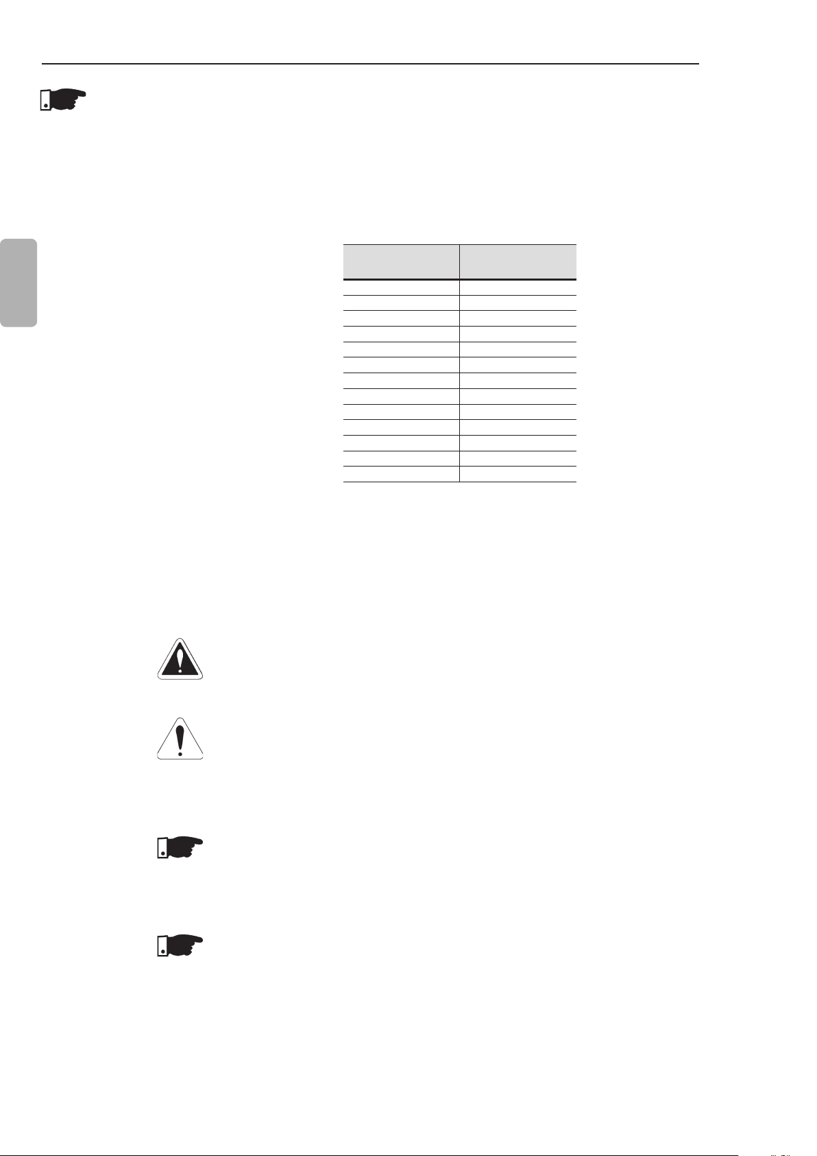
3.2.4.3 Recommended Contactors
English
3.2.5 Soft-Starter
SSW-07
Connection to
the Motor
When the SSW-07 is used in applications that require an isolator
contactor, according to the gure 3.10 (K1), the use of WEG
contactors is recommended.
SSW-07 Model WEG Contactor
17 A CWM18
24 A CWM25
30 A CWM32
45 A CWM50
61 A CWM65
85 A CWM95
130 A CWM150
171 A CWM180
200 A CWM250
255 A CWM250
312 A CWM300
365 A CWME400
412 A CWME400
Table 3.8 - Recommended contactors
DANGER!
Power factor correction capacitors must never be installed at the
output of the Soft-Starter SSW-07. (U / 2T1, V / 4T2 and W / 6T3).
ATTENTION!
To ensure that the protections based on the current reading and
display operate correctly, for example the overload, the motor
nominal current must not be lower than 50 % of the nominal SoftStarter SSW-07 current.
NOTE!
Use the wire sizes and fuses recommended in tables 3.5, 3.6 and
3.7. The connector tightening torque is indicated in table 3.4. Use
only copper wires.
NOTE!
The Soft-Starter SSW-07 is provided with electronic protection
against motor overload. This protection must be set according to
the specic motor. When several motors are connected to the same
Soft-Starter SSW-07 use individual overload relays for each motor.
20
Page 22
CHAPTER 3 - INSTALLATION AND CONNECTION
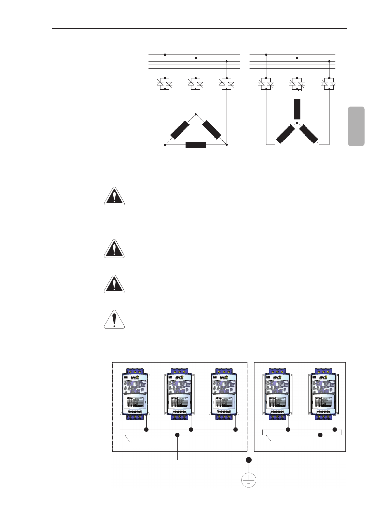
3.2.5.1 Standard Three-Wire Connection
3.2.6 Grounding
Connections
Line current of the Soft-Starter SSW-07 is equal to the motor current.
R
S
T
N
PE
R
U
1/U1
S
V
4/U2
6/W2
3/W1
T
2/V1
5/V2
Figure 3.7 - Soft-Starter SSW-07 with standard connection
R
S
T
N
PE
R
W
U
1/U1
2/V1
4/U2
S
5/V2
6/W2
T
WV
3/W1
DANGER!
The Soft-Starter must be grounded for safety purposes (PE).
The ground connection must comply with the local regulations.
Make the ground connection to a grounding bar or to the general
grounding point (resistance ≤10 ohms).
English
DANGER!
The AC input for the Soft-Starter SSW-07 must have a ground
connection.
DANGER!
Do not use the neutral conductor for grounding purpose. Use
dedicated ground conductor.
ATTENTION!
Do not share the ground wiring with other equipment that operate
with high current (for examples: high voltage motors, welding
machines, etc.). When several Soft-Starters SSW-07 are used,
observe the connections in the gure 3.8.
GROUNDING BAR
BARRA DE ATERRAMENTO
INTERNAL TO THE PANEL
INTERNA AO PAINEL
GROUNDING BAR
BARRA DE ATERRAMENTO
INTERNAL TO THE PANEL
INTERNA AO PAINEL
Figure 3.8 - Grounding connections for more than one Soft-Starter SSW-07
21
Page 23
CHAPTER 3 - INSTALLATION AND CONNECTION
EMI - Electronic Interference
The Soft-Starter SSW-07 is developed to be used in industrial
systems (Class A) according to Standard EN60947-4-2.
It’s necessary to have a distance of 0.25 m (10 in) between the
Soft- Starter SSW-07 control cables and motor cables.
Example: PLC wiring, temperature controllers, thermocouple cables, etc.
Grounding of the Motor frame
Always ground the motor frame. The Soft-Starter SSW-07 output
wiring to the motor must be installed separately from the input wiring
as well as from the control and signal wiring.
English
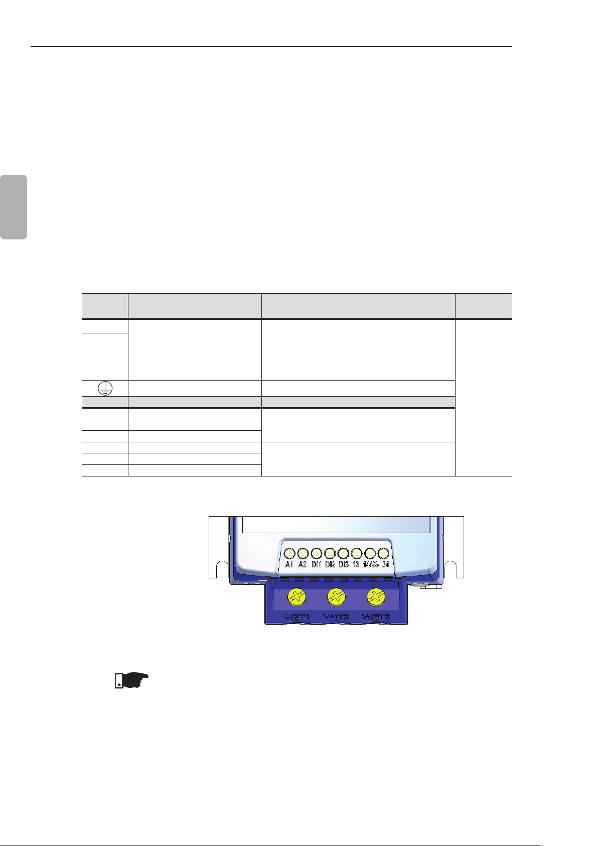
3.2.7 Control and Signal Connections
Terminal Description Specications
A1
A2
Terminal Factory Default Specications
DI1 Starts/Stops Motor
DI2 Fault reset
DI3 Fault reset
13 Relay 1 output - Operation
14/23 Relay common point
24 Relay 2 output - Full voltage
The control connections (digital inputs and relay outputs) are made
through the terminals (refer to gure 3.9).
Voltage: 110 to 240 Vac (-15 % to +10 %)
(models from 17 A to 200 A)
Electronics Supply
Grounding Only for the 255 to 412 A models
Table 3.9 - Description of the control connector pins
110 to 130 Vac or 208 to 240 Vac
(-15 % to 10 %) (models from 255 A
to 412 A).
3 isolated digital inputs
Voltage: 110 to 240 Vac (-15 % to +10 %)
Current: 2 mA Max.
Contact capacity:
Voltage: 250 Vac
Current: 1 A
Torque Nm
(in lb)
0.5 (4.5)
22
Figure 3.9 - Control terminals of the Soft-Starter SSW-07
NOTE!
It is recommended to use shielded cables for the Dix inputs when
using long cables (above 30 m) in noisy environments. The metallic
shield and A2 must be grounded.
Page 24
CHAPTER 3 - INSTALLATION AND CONNECTION
3.3 RECOMMENDED SET-UPS
Some recommended set-ups are shown here and they can be
completely or partly used.
The main warning notes for all the recommended set-ups are
shown below and are described in the schemes by their respective
numbers.
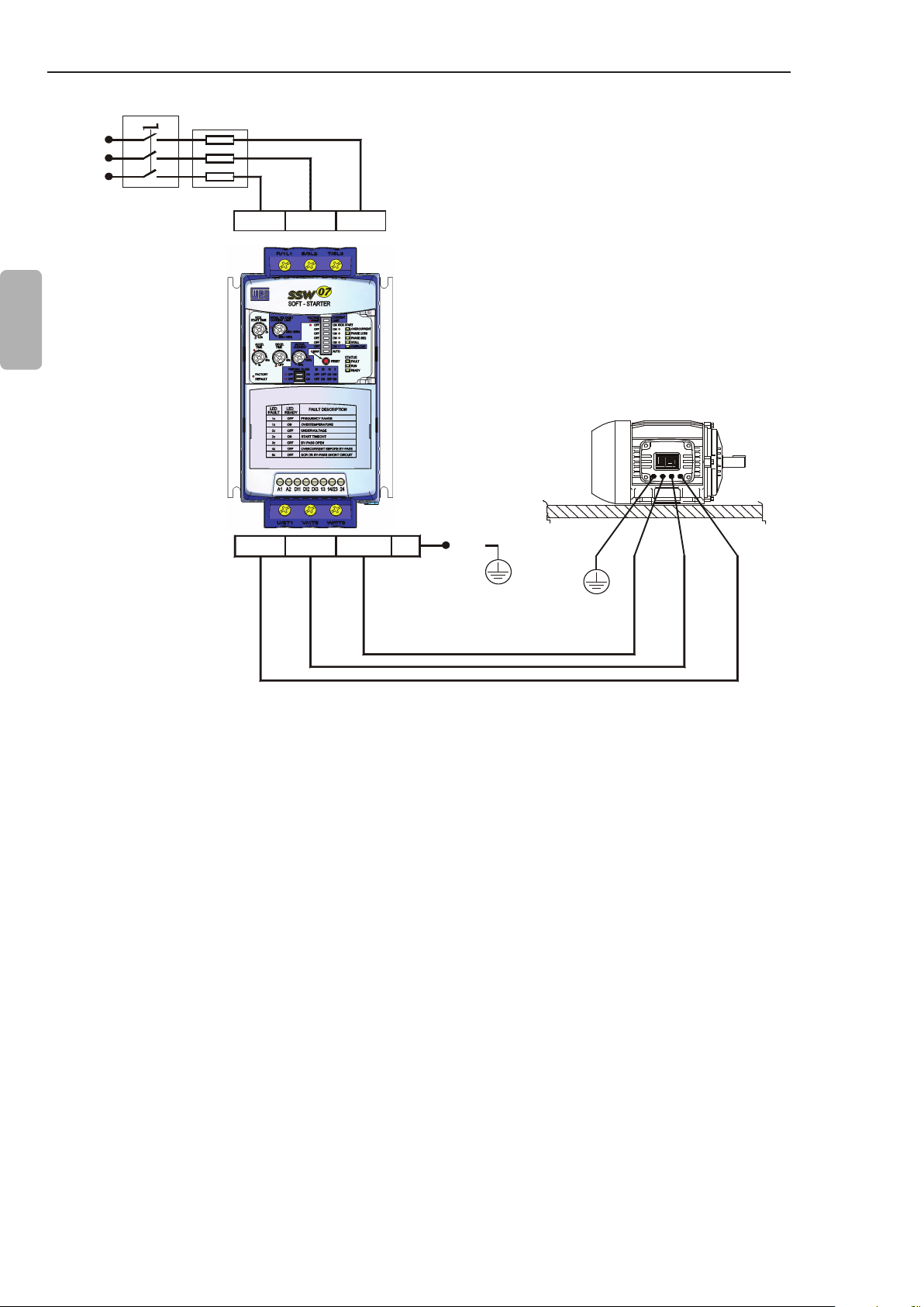
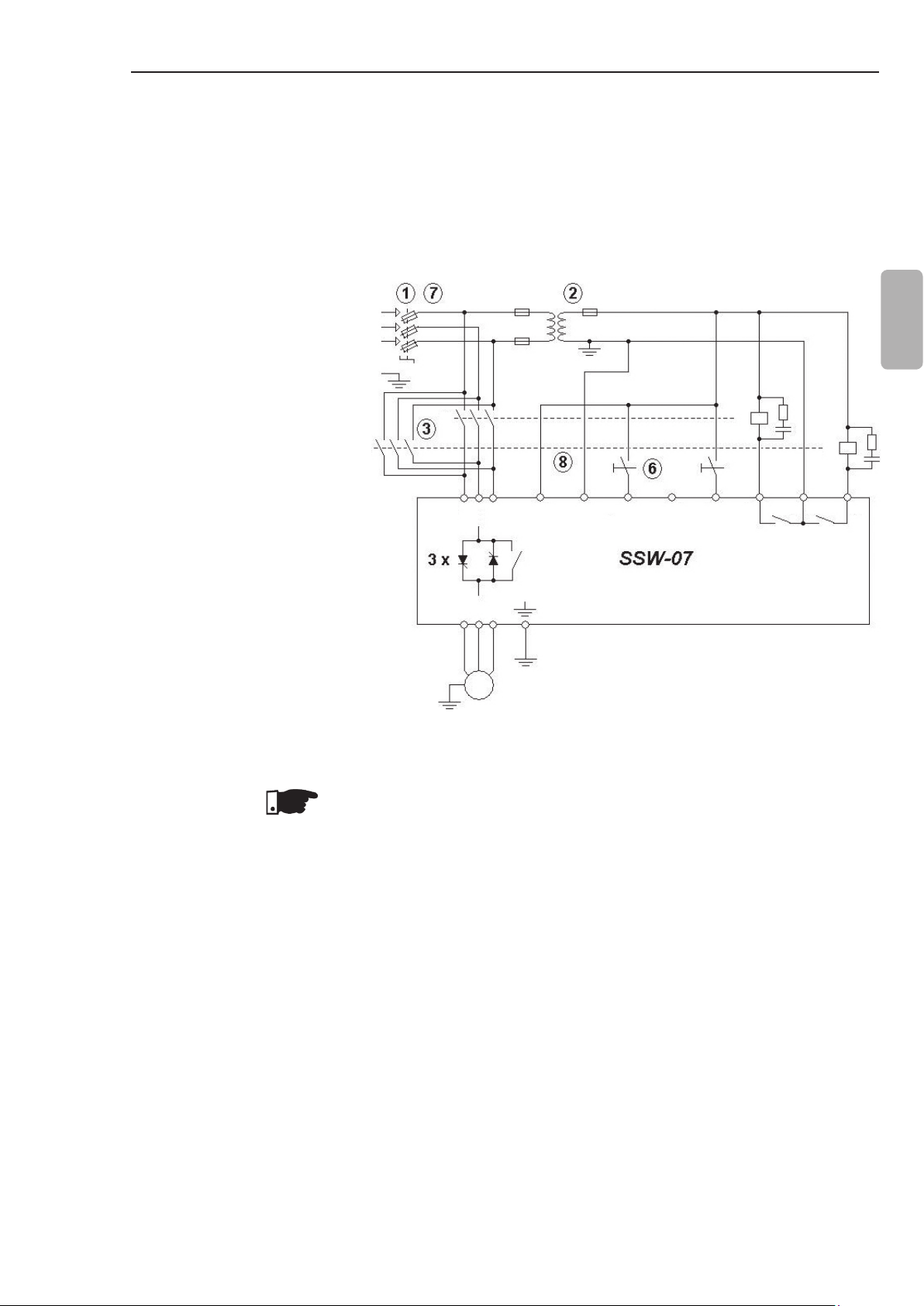
NOTES!
The use of fuses or circuit breakers at the input circuit is
1
necessary for the entire installation protection. It is not necessary
to use ultra-fast fuses for the SSW-07 operation; however, their
use is recommended for the soft-starter complete protection.
The transformer “T1” is optional and must be used when there
2
is a difference between the line voltage and the electronic power
voltage.
In case that damage at the SSW-07 Soft-Starter power circuit
3
keeps the motor running (e.g., shorted thyristors), the motor
protection is obtained with the use of the power isolating
contactor (K1) or circuit breaker (Q1).
English
Start push-button.
4
Stop push-button.
5
Start/Stop switch. Bear in mind that when using two-wire digital
6
input command (normally open switch with retention), in case
of a power interruption, upon return of power, the motor will be
started immediately if the switch remains closed.
In case of maintenance of the Soft-Starter SSW-07 or the motor
7
it is necessary to remove the input fuses or disconnect the power
supply to ensure the complete equipment disconnection from
the power supply.
The emergency stop can be used by disconnecting the
8
electronics power supply.
Undervoltage release for the Q1 power isolation circuit breaker.
9
23
Page 25
CHAPTER 3 - INSTALLATION AND CONNECTION
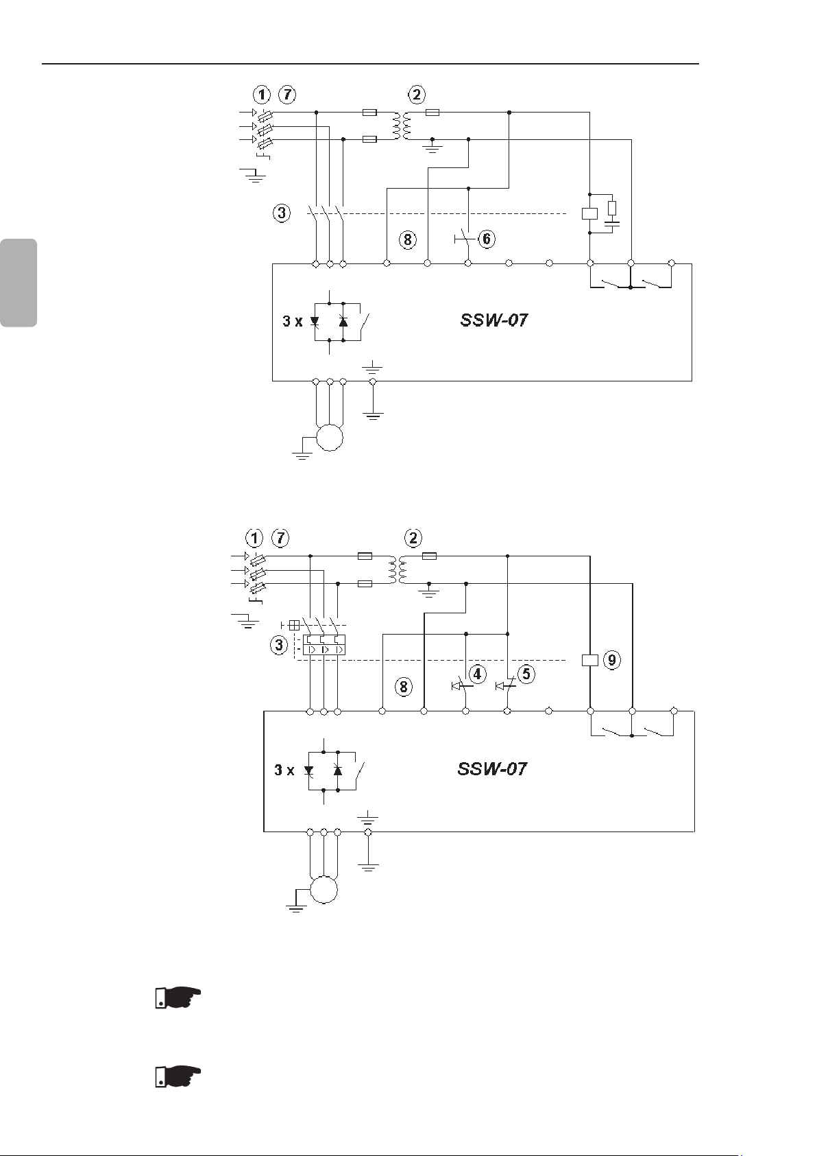
3.3.1 Recommended Set-up with Command via Two-wire Digital Inputs and Isolation Contactor
English
Refer to notes in item 3.3.
R
S
T
PE
K1
R S T
U V W
M
3~
T1
K1
RL1
23
14
24
RL2
DI1A2A1
DI2
DI3
13
Figure 3.10 - Recommended set-up with commands via two-wire digital inputs
and isolation contactor
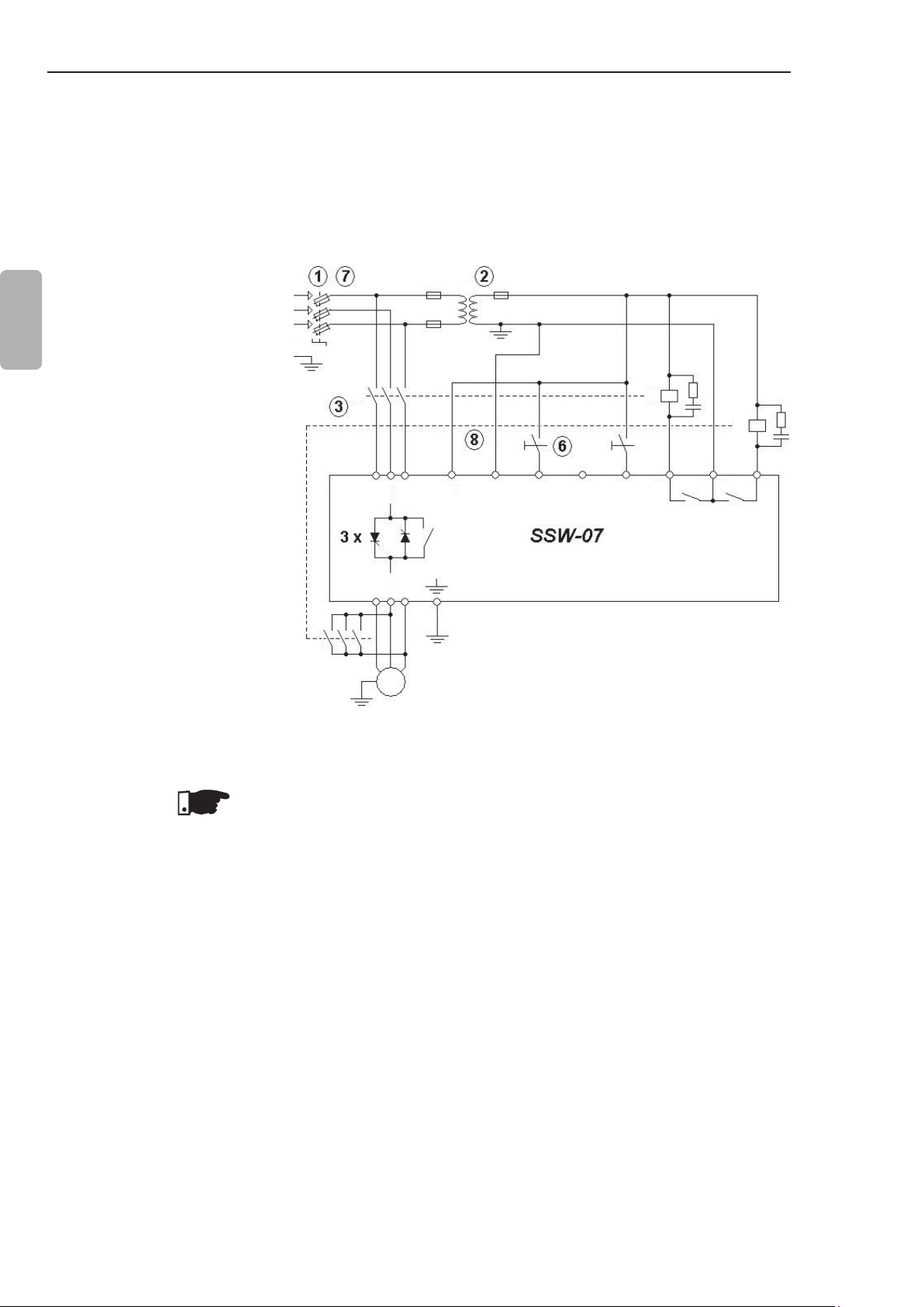
3.3.2 Recommended
Set-up with
Command
via Threewire Digital
Inputs and
Circuit- Breaker
Refer to notes in item 3.3.
R
S
T
PE
Q1
R S T
U V W
M
3~
T1
Q1
DI1A2A1
DI2
DI3
13
14
23
RL1 RL2
24
24
Figure 3.11 - Recommended set-up with commands via three-wire digital
inputs and a circuit-breaker
NOTE!
It’s necessary to program the digital input DI2 for the three-wire
command function. Refer to item 4.10.
NOTE!
The RL1 shall be set to the “No fault” function. Refer to item 4.12.
Page 26
3.3.3 Recommended Set-up with Command via Two-wire Digital Inputs and Direction of Rotation
P220 = 1
P230 = 1
P263 = 1 (DI1 = Start/Stop two
wires)
P265 = 4 (DI3 = Rotation
Direction)
P277 = 4 (RL1 = FWD/REV - K1)
P278 = 4 (RL2 = FWD/REV - K2)
CHAPTER 3 - INSTALLATION AND CONNECTION
R
S
T
PE
K1
K2 K2
T1
K1
English
Refer to notes in item 3.3.
Figure 3.12 - Recommended Set-up with Command via Two-wire Digital
NOTE!
To program the parameters shown above, is necessary the use of
keypad or serial communication. See the Programming Manual for
more information.
R S T
U V W
M
3~
DI1A2A1
Inputs and Direction of Rotation
DI2
DI3
RL1
23
14
24
RL2
13
25
Page 27
CHAPTER 3 - INSTALLATION AND CONNECTION
3.3.4 Recommended
Set-up with
Command via
Two-wires Digital
Inputs and DCBraking
P220 = 1
P230 = 1
P263 = 1 (DI1 = Start/Stop two
wires)
English
P265 = 5 (DI3 = Brake Off)
P277 = 1 (RL1 = Running)
P278 = 5 (RL2 = DC-Braking)
P501 ≥ 1 (DC Braking Time ≥ 1s)
R
S
T
PE
K1
T1
K1
K2
Refer to notes in item 3.3.
NOTE!
To program the parameters shown above, is necessary the use of
keypad or serial communication. See the Programming Manual for
more information.
K2
R S T
U V W
M
3~
DI1A2A1
DI2
DI3
13
RL1
23
14
24
RL2
Figure 3.13 - Recommended Set-up with Command via Two-wires Digital
Inputs and DC-Braking
26
Page 28
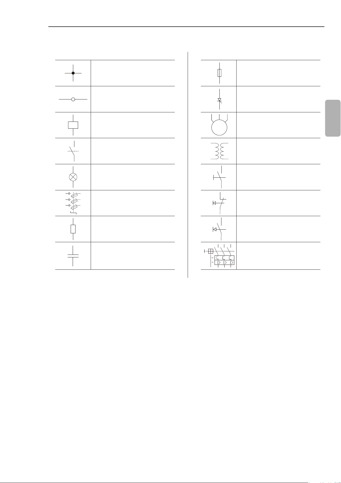
3.3.5 Symbols
CHAPTER 3 - INSTALLATION AND CONNECTION
Electrical connection between
two signals
Connection terminals Thyristor/SCR
Relay or contactor coil
M
3~
Normally open contact (NO) Transformer
Indicator light N.O Contact (with retention)
Circuit-breaker
(opens under load)
Resistor Normally open (NO)
Fuse
Three-phase motor
Normally closed (NC)
push-button
push-button
English
Capacitor Circuit-breaker with
undervoltage release
27
Page 29
CHAPTER 4
SETTING THE SSW-07
This chapter describes how to make the necessary settings for the
correct functioning of the SSW-07.
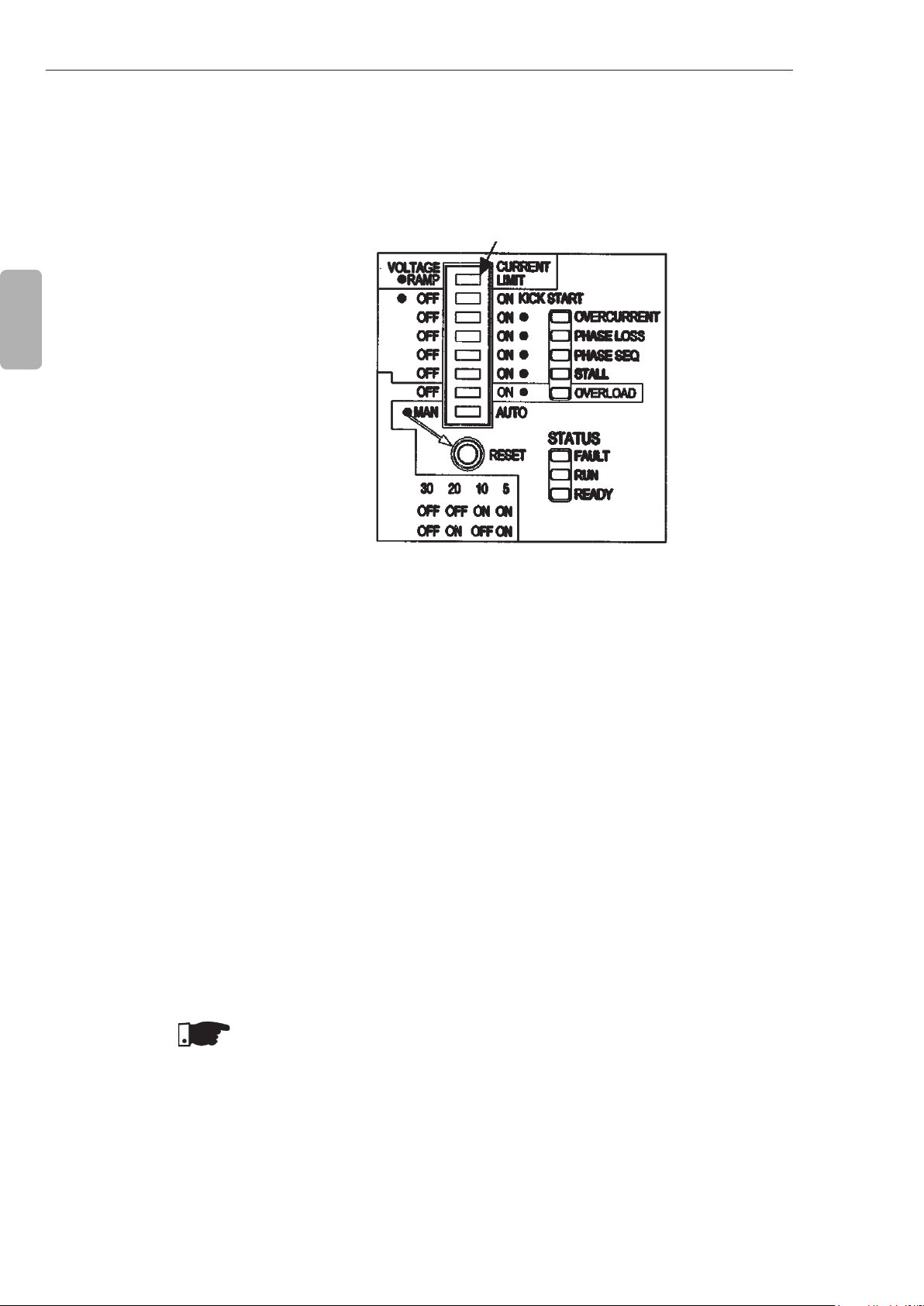
4.1 CONTROL TYPE SETTING
English
DIP Switch Control
Type Setting
Figure 4.1 - Control type setting
Select the type of starting control that best adapts to the application.
Voltage Ramp Starting:
This is the most commonly used method. Very easy to program
and set.
The Soft-Starter SSW-07 imposes the voltage applied to the motor.
Generally applied to loads with a lower initial torque or a square
torque.
This kind of control can be used as an initial working test.
Current Limit Starting:
The maximum current level is maintained during the start, being set
according to the application necessities.
Generally applied to loads with a higher initial torque or a constant
torque.
This kind of control is used to adapt the start to the capacity limits
of the supply network.
NOTES!
1. The Current Ramp control type, is only programmed using keypad
or serial communication. See the Programming Manual for more
details.
2. To program the control type in Pump control, see the Programming
Manual or item 5.1.4.
28
Page 30

CHAPTER 4 - SETTING THE SSW-07
4.2 KICK START
Kick Start Enabling
DIP Switch
English
Figure 4.2 - Kick Start enabling
Soft-Starter SSW-07 offers a Kick Start function for loads that
present a large initial resistance to movement.
This function is enabled through the Kick Start DIP Switch. The
duration of the voltage pulse is set through the trimpot Kick Start
Time.
The voltage pulse applied is of 80 % Un during the programmed
trimpot Kick Start Time.
4.3 INITIAL VOLTAGE SETTING
NOTE!
Use this function only for specic applications and where necessary.
Set the initial voltage to a value that the motor starts to run as soon
as the start command is given to the SSW-07.
Initial Voltage
Setting Trimpot
The dot indicates
the factory default
setting
Figure 4.3 - Initial voltage setting
29
Page 31

CHAPTER 4 - SETTING THE SSW-07
NOTE!
The Initial Voltage trimpot has an initial voltage setting function only
when the kind of control is programmed to start with a voltage ramp.
4.4 CURRENT LIMIT SETTING
English
This setting denes the maximum limit of the current during motor
starting in percentage of the nominal current of the Soft-Starter.
If the current limit is reached during the start of the motor, SoftStarter SSW-07 will maintain the current at this limit until the motor
reaches nominal speed.
If the current limit is not reached, the motor will start immediately.
The current limitation should be set to a level that the motor
acceleration can be observed, otherwise the motor will not start.
Current Limit
Setting Trimpot
Figure 4.4 - Current limit setting
NOTES!
If at the end of the acceleration ramp (set at the Trimpot Acceleration
Time), full voltage is not reached, a start timeout Fault will be shown.
This fault is indicated through the Fault LED ashing twice with the
Ready LED on.
The trimpot Current Limit has a Current Limit setting function only
when the kind of control is programmed to start with a Current Limit.
30
Page 32

CHAPTER 4 - SETTING THE SSW-07
4.5 ACCELERATION RAMP TIME SETTING
When Soft-Starter SSW-07 is programmed to Voltage Ramp control,
this is the voltage increment ramp time.
When Soft-Starter SSW-07 is programmed to Current Limit control,
this time is used as the maximum starting time, working as a
protection against blocked rotors.
English
Acceleration Ramp
Time Setting Trimpot
Figure 4.5 - Acceleration ramp time setting
NOTE!
The programmed acceleration time is not the exact motor
acceleration time, but the time of the voltage ramp or the maximum
starting time. The motor acceleration time depends on the motor
characteristics and the load.
4.6 DECELERATION RAMP TIME SETTING
Please consider that in cases where the relation of the SSW-07
current and the motor nominal current is 1.00, the maximum time
that the SSW-07 can work with 3 x In is 30 seconds.
Enables and sets the time of voltage decrease.
This setting should be used only for the deceleration of pumps to
reduce the water hammer. This setting must be made to achieve
the best pump performance.
NOTE!
This function is used to lengthen the normal deceleration time of a
load and not to force a lower time than that imposed by the load itself.
31
Page 33

CHAPTER 4 - SETTING THE SSW-07
English
Deceleration Ramp
Time Setting Trimpot
Figure 4.6 - Deceleration ramp time setting
4.7 MOTOR CURRENT SETTING
This setting denes the ratio of the SSW-07 current and the motor
current. The value of the setting is very important since it denes
the protection of the motor driven by the SSW-07. The setting of
this function interferes directly in the following motor protections:
-Overload;
-Overcurrent;
-Stall;
-Phase loss.
Calculation Example:
SSW-07 Used: 30 A
Motor Used: 25 A
Trimpot for the Motor Current Setting
Motor Current Setting = I
motor
I
SSW-07
Motor Current Setting = 25 A
30 A
32
Motor Current Setting = 0.833
Therefore it must be set at 83 %
Page 34

CHAPTER 4 - SETTING THE SSW-07
Motor Current
Setting Trimpot
Figure 4.7 - Motor current setting
English
4.8 MOTOR ELECTRONIC OVERLOAD PROTECTION
The motor electronic overload protection simulates the heating and
cooling of the motor, also known as thermal image. This simulation
uses as input data the True rms current.
When the thermal image passes the limit, the overload protection
trips and turns the motor off.
The adjustment of the thermal class is based on the motor locked
rotor current and locked rotor time. With this data it is possible to
nd a point in the gure to determine, which thermal class protects
the motor. Please refer to gure 4.8 for cold stall time or to gure
4.9 for hot stall time. The thermal classes below the point protect
the motor.
33
Page 35

CHAPTER 4 - SETTING THE SSW-07
Time t(s)
10000
1000
English
100
10
1
S.F.=1 1x 2x 3x 4x 5x 6x 7x 8x 9x
S.F.=1,15 1x 2x 3x 4x 5x 6x 7x 8x 9x 10x
Class 30
Class 25
Class 20
Class 15
Class 10
Class 5
x In motor
current
Figure 4.8 - Thermal classes of motor protection in cold condition
Time t(s)
1000
100
34
10
Class 30
Class 25
Class 20
Class 15
1
0.1
1x 2x 3x 4x 5x 6x 7x 8x 9x S.F.=1
Class 10
Class 5
x In motor
Current
Figure 4.9 - Motor protection thermal classes in hot condition at 100 % ln
Page 36

CHAPTER 4 - SETTING THE SSW-07
Overload Protection
Enabling DIP Swicth
Thermal class adjustment DIP Switches
Figure 4.10 - Overload protection Enabling and Adjustment
NOTES!
Adjust the motor current according to chapter 4.7 for the correct
function of the overload protection;
This protection is based on Three Phase IP55 Standard WEG
motors. If your motor is different, we recommend to adjusting a
lower thermal class. For more details refer to chapter 5.2;
When SSW-07 is without the electronic supply voltage (A1 and
A2), the thermal image is saved internally. When the supply (A1
and A2) is reestablished, the thermal image returns to the value
prior to the electronic supply loss;
The RESET of the electronic overload protection can be set to
manual function (man). In this case the RESET must be made
via digital input 2 (DI2) or through the RESET key. If the RESET
setting is automatic (auto), the fault condition will automatically
be reset after the cooling time;
The thermal image is set to zero, when the overload protection
is disabled.
English
35
Page 37

CHAPTER 4 - SETTING THE SSW-07
4.9 RESET
English
A fault condition can be reset using the RESET key at the front of
the SSW-07 or through a push-button (0.5 seconds) at DI3 (digital
input for RESET). Another way to reset the SSW-07 is by switching
Off/On the electronic power supply (A1 and A2).
NOTE!
The SSW-07 also allows for the possibility of automatic RESET by
enabling this function through the DIP Switch (auto):
Automatic RESET occurs after 15 minutes in the following
conditions:
-Overcurrent;
-Phase loss;
-Stall;
-Overcurrent before By-pass;
-Frequency out of range;
-Contact of the internal By-pass relay is open;
-Power control supply undervoltage;
-External fault.
For incorrect phase sequence there is no automatic RESET.
For electronic overload of the motor there is a specic algorithm
for the automatic RESET time.
4.10 DI2 DIGITAL INPUT SETTING
In the factory default, the DI2 digital input has its function programmed
for the reset of faults. DI2 can also be programmed to work as a
three wire control.
The three wire control allows the Soft-Starter to be commanded
through two digital inputs, DI1 as an ON input and DI2 as an OFF
input. This allows for the direct placement of two push buttons.
Refer to item 3.3.2.
To change the DI2 digital input, follow the instructions below:
1. To enter in programming mode, maintain the reset key at the
front of the SSW-07 pressed for 5 seconds. Maintain the reset
key pressed during programming;
2. When in programming mode, two LEDs will turn on (overcurrent
and phase loss), indicating that DI2 is programmed for fault Reset.
When three LEDs turn on (overcurrent, phase loss and phase
sequence), it indicates that the DI2 is programmed for three wire
commands;
3. To change the programming to three wire commands, move the
overcurrent DIP Switch and return to the previous position. The
three LEDs will turn on, indicating that DI2 is programmed for
three wire commands;
4. To change the DI2 programming to fault Reset, move the Kick
Start DIP Switch and return to the previous position. Two LEDs
will turn on, indicating that the DI2 is programmed for fault Reset;
5. Programming is concluded when the reset key is released.
36
Page 38

CHAPTER 4 - SETTING THE SSW-07
4.11 OUTPUT RELAY OPERATION
Operation Function
The relay of the Operation Function closes its N.O. contact
(13-14/23) every time the SSW-07 receives the enable command.
This contact is only opened at the end of the deceleration ramp
(when it is set via trimpot) or when the SSW-07 receives the
disable command.
The relay of the Full Voltage Function closes the N.O. contacts
(14/23-24) every time the SSW-07 applies 100 % of the voltage to
the driven motor. This contact opens when the SSW-07 receives
the disable command.
(Motor Voltage)
U
N
100 %
t
(13- 14/23)
t
Relay on
English
4.12 RELAY OUTPUT RL1 PROGRAMMING
Full Voltage Function
(14/23-24)
In the factory default programming, the relay output RL1 has its
function programmed for “Operation”. RL1 (13/14) can be also be
programmed for the “No Fault” function. This function allows the
installation of a circuit breaker with an undervoltage release at the
SSW-07 input. Refer to gure 3.3.2. In order to change the relay
output RL1 programming follow these instructions:
1. To enter in programming mode keep the reset key, at the SSW-07
front cover, pressed during 5 seconds, keeping it also pressed
throughout the programming;
2. When in the programming mode two LEDs turn on (Overcurrent
and Phase Loss), indicating that DI2 is programmed for Error
Reset. If three LEDs turn on (Overcurrent, Phase Loss and Phase
Sequence), it indicates that DI2 is programmed for three-wire
command. If the Overload LED turns on, then the RL1 function
is “No Fault”, otherwise the function is “Operation”;
3. To modify the RL1 function change the Overload DIP Switch
and put it back in the previous position. The Overload LED will
indicate the new programmed function:
- Overload LED off: Operation function;
- Overload LED on: No Fault function.
t
Figure 4.11 - Output relay operation
37
Page 39

5.1 APPLICATIONS AND PROGRAMMING
English
CHAPTER 5
PROGRAMMING INFORMATION AND SUGGESTIONS
This chapter helps the user to set the types of starting controls
according to their applications.
ATTENTION!
Suggestions and important notes for each type of starting control.
ATTENTION!
To know the correct programming of the parameters, have your
load data on hand and use the WEG (Soft-Starter) Dimensioning
Software available at WEG’s home page (http://www.weg.net).
If you are unable to use the software mentioned above, you can
follow some practical concepts described in this chapter.
Shown below are some characteristic curves with current and
starting torque behavior according to some kinds of control.
I/In
T/Tn
Current
Torque
Tn
I/In
T/Tn
38
Tn
Current
Torque
Figure 5.1 - Characteristic curves of torque and current in a direct on-line start
and by voltage ramp
Page 40

CHAPTER 5 - PROGRAMMING INFORMATION AND SUGGESTIONS
I/In
T/Tn
5.1.1 Voltage Ramp Starting
Current
Torque
Figure 5.2 - Characteristic curves of torque and current in a
current limitation start
Tn
1) Set the value of the initial voltage to a low value;
2) When a load is applied to the motor, set the initial voltage to a
value that makes the motor rotate smoothly from the instant it is
started.
3) Set the acceleration time with the necessary start time, initially
with short times, 10 to 15 seconds, and afterwards try to nd the
best starting condition for the used load.
U(V)
Start
100 %Un
English
0
Enable
Figure 5.3 - Voltage ramp starting
Voltage Ramp
t(s)
Disable
NOTES!
With long starting times, or when the motor is without a load,
vibration can occur during the start of the motor, therefore lower
the starting time;
If faults occur during the start, check all the connections from the
Soft-Starter to the supply network, motor connections, supply
network voltage levels, fuses and circuit breakers.
39
Page 41

CHAPTER 5 - PROGRAMMING INFORMATION AND SUGGESTIONS
5.1.2 Current Limit Starting
English
1) To start with a current limitation it is necessary to start with a load.
Initial test without load can be done with a voltage ramp;
2) Set the acceleration time with the necessary starting time, initially
with short times, 20 to 25 seconds. This time will be used as the
stall time in case the motor does not start;
3) Set the current limit according to the conditions that your electric
installation allows, as well as to the values that supply enough
torque to start the motor. It can initially be programmed with values
between 2x and 3x the nominal current of the motor (ln of the motor).
I(A)
Start
I Limitation
I Nominal
Maximum Time
0
Enable
Current Limitation
t(s)
Disable
5.1.3 Starting with Pump Control (P202 = 2)
Figure 5.4 - Current limit starting
NOTES!
If the current limit is not reached during the start, the motor will
start immediately;
Very low Current Limit values do not provide sufcient torque to
start the motor. Always keep the motor rotating once it is started.
For loads that need a higher initial starting torque, the Kick Start
function can be used;
If faults occur during the start, check all the connections from the
Soft-Starter to the supply network, motor connections, supply
network voltage levels, fuses and circuit breakers.
1) To start with pump control a load is necessary. No-load tests can
be done with voltage ramp;
2) The starting parameters setting depend mainly on the types of
hydraulic installations. Thus we recommend optimizing factory
settings, if possible.
3) Check if the motor rotation direction is an indicated on the pump
frame. If not, connect the phase sequence as indicated at P620;
40
Figure 5.5 - Direction of rotation of a hydraulic centrifugal pump
Page 42

CHAPTER 5 - PROGRAMMING INFORMATION AND SUGGESTIONS
4) Set the initial voltage - P101 – so the motor starts smoothly as
soon as it is enabled.
5) Set the acceleration time according to the application, and, that
the motor is able to start the load smoothly, but the required
acceleration is not exceeded. If acceleration times are set too
long, this may result in vibration or harmful motor overheating;
6) To check the correct starting process, always use a manometer
in the hydraulic installation. Pressure increase should not result
in sudden oscillations. Thus the pressure increase should be as
linear as possible;
English
U(V)
P101
0
Figure 5.6 - Manometer showing pressure increase
P102
Enable
100%UnStart
Pump Control
7) Program the deceleration initial voltage (P103) only when no
pressure drop is detected at the deceleration begin. With this
deceleration initial voltage you can improve the linear pressure
drop during the deceleration;
8) Set the deceleration time according to the application, and,
ensuring that the pump stops smoothly within the expected
limits. The set of excessively long times may result in vibrations
or harmful motor overheating;
U(V)
Figure 5.7 - Manometer showing the pressure drop
100%Un
0
P103
Parada
P104
Pára
P105
t(s)
9) Generally, the current increases at the end of the deceleration ramp
and in this case the motor requires more torque to achieve a smooth
water ow stop. When the motor has already stopped, but is still
enabled, the current will increase too much. To prevent this condition,
set P105 to a value that as soon it stop it is also disabled;
41
Page 43

CHAPTER 5 - PROGRAMMING INFORMATION AND SUGGESTIONS
10)Set P610 and P611 to current and time levels that prevent the
hydraulic pump from running without a load.
English
U(V)
P101
Start
0
Pump Control
Figure 5.8 - Start with pump control
100%Un
P103
DisableEnable
Stop
P104P102
P105
t(s)
NOTES!
1) If the hydraulic piping is not tted with a manometer, the water
hammer can be noted at the pressure relief valves;
2) Please, consider that sudden line voltage drops results in motor
torque drops. Thus, ensure that the power supply line characteristics
are within the characteristics required for motor operation;
3) If errors are detected during the motor start, check all connections
of the Soft-Starter to the power line, the motor connections, the
voltage levels of the power line, the fuses, circuit-breakers and
disconnecting switches.
5.1.4 Programming the control type in pump control
Is recommended program the control type in pump control using
keypad or serial communication, see the Programming Manual
for more details. In special cases, when is not available keypad or
serial communication, is also possible to program the control type
in pump control following these instructions:
1) To enter in programming mode, keep the reset key at the SSW-07
front cover pressed during 5 seconds, keeping it also pressed
throughout the programming;
2) When in the programming mode, LEDs will turn on indicating the
actual parameterization. See item 4.10 and 4.12;
3) To modify the control type, change the Stall DIP Switch and put
it back in the previous position. The Stall LED will indicate the
new programmed control type:
- LED Stall off: P219=0. Control type dened through Voltage
Ramp/Current Limit DIP Switch.
- LED Stall on: P219=2. Control type in Pump Control and
parameterization through Trimpots and DIP Switches.
42
Page 44

CHAPTER 5 - PROGRAMMING INFORMATION AND SUGGESTIONS
5.2 PROTECTIONS AND PROGRAMMING
5.2.1 Suggestion on
How to Program
the Thermal
Class
For each application exists a range of thermal classes, which might
be set. The overload protection should not trip during normal starting.
Therefore it is necessary to know the starting time and current, to
determine the minimum thermal class. The maximum thermal class
depends on the motor limit.
Determine the minimum thermal class:
1) Initially start at the standard thermal class, sometimes, but without
the motor overheating;
2) Determine the correct starting time and nd an average of the
current using a multimeter with a current probe to measure it; A
current average can be found for any type of starting control;
For example:
Starting an 80 A motor using a voltage ramp. The current starts at
100 A and goes to 300 A, returning afterwards to the nominal value
in 20 seconds.
(100 A + 300 A)/2 = 200 A
200 A/80 A = 2.5 x ln of the motor
Therefore: 2.5 x ln @ 20 seconds.
English
U(V) Start
Initial Voltage
P101
Figure 5.9 - Typical current curve during a voltage ramp start
100 A
0
Enable
P102
Accel Time
100 % Un
300 A
Motor
Current
t(s)
20 s
3) Use this time to nd the minimum class necessary to start the
motor in cold condition. In the item 4.8 Motor Electronic Overload
Protection it is possible to check the thermal class curves of the
motor in cold condition.
43
Page 45

CHAPTER 5 - PROGRAMMING INFORMATION AND SUGGESTIONS
t(s)
Cold
English
20 s
0
2.5 x ln of the
motor
Figure 5.10 - Checking the minimum class of curves in cold condition
F.S.=1
15
10
5
xln
Therefore the minimum class necessary to start the cold motor is
Class 10. Class 5 will trip during starting.
NOTE!
If the motor must start in the hot condition, class 10 will trip during
the second start. In the case a higher thermal class must be set.
Determine the maximum thermal class:
To correctly program the Thermal Class that will protect your motor it
is essential to have in hand the motor locked rotor current and locked
rotor time. This information is available in the motor manufacturer’s
catalogue. Put these values into gure 4.8, in case of the cold stall
time or into gure 4.9, in case of hot stall time.
For example:
Stall Current = 6,6 x ln
Hot Stall Time = 6s
t(s)
Hot
6 s
0
6.6 x ln of the
motor
Figure 5.11 - Checking the maximum class of curves in hot condition
Class 25 is the highest class that protects the motor.
30
25
20
xln
44
Page 46

CHAPTER 5 - PROGRAMMING INFORMATION AND SUGGESTIONS
NOTE!
Remember that this protection has as a standard the Three Phase
IP55 Standard WEG Motor, therefore if your motor is different, then
do not program the thermal class to its maximum, instead, program
it near its minimum thermal class to start.
Example of how setting the thermal class:
Motor data:
Power: 50 hp
Voltage: 380 V
Nominal Current (ln): 71 A
Service Factor (S.F.): 1.00
lp/ln: 6.6
Stall time: 12 s in hot condition
Speed: 1770 rpm
Motor + load starting data:
Starting by Voltage Ramp, starting current average:
3 x the nominal current of the motor during 17 s (3 x ln @ 17 s).
1) In the graph, gure 4.8 in cold condition, one can see the minimum
Thermal Class that will allow the start with a reduced voltage:
For 3 x ln of the motor @17 s, the next highest is adopted: Class 10.
2) In the graph, gure 4.9 in hot condition, one can see the maximum
Thermal Class that the motor can stand due to the stall time in hot
condition:
For 6.6 x ln of the motor @ 12 s, the next lowest is adopted. Class 30.
English
5.2.2 Service Factor
One now knows that Thermal Class 10 allows a start and Thermal
Class 30 is the maximum limit. Thus, a Thermal Class between the
two should be adopted, according to the quantity of starts per hour
and the interval of time between Off/On procedures the motor.
The closer to Class 10, the more protected the motor will be, the
fewer the starts per hour and the greater the interval of time must
be between Off/On procedures the motor.
The closer to Class 30, the closer it gets to the maximum limit of the
motor, thus there can be more starts per hour and lower intervals of
time between Off/On procedures the motor.
When the Service Factor (S.F.) is different from 1.00 and if there is
the need to use it in the application, this must be considered in the
setting of the overload protection. To avoid tripping of the overload
protection, when the service factor is used, the nominal motor current
set at the SSW-07 must be readjusted. If an acessorie with parameter
access is used, the service factor can be set directly in the P406,
avoiding the readjustment of the nominal currrent.
45
Page 47

CHAPTER 5 - PROGRAMMING INFORMATION AND SUGGESTIONS
Example of readjustment of the nominal current:
I
I
SSW-07
MOTOR
= 30 A
= 25 A
S. F. = 1.15
English
Setting of the Motor Current = I
MOTOR
x S.F. / I
= 25 A x 1.15 /
SSW-07
30 A = 96 %
ATTENTION!
The increased motor current has direct impact on the maximum
thermal class, that protects the motor, even if the S.F. parameter is
set.
Determine the maximum thermal class, considering the service
factor:
Stall Current = 6.6 x ln
Hot Stall Time = 6 s
Service Factor = 1.15
Before the maximum thermal class is veried in gure 4.9, the stall
current must be divided by the service factor.
Stall Current / S.F. = 6.6 / 1.15 = 5.74
t(s)
Hot
6 s
25
20
15
0
5.74 x In of the motor
Figure 5.12 - Checking of the maximum thermal class, considering the S.F.
xln
Class 20 is the highest class that protects the motor, if the service
factor is used.
46
Page 48

SOLUTION AND TROUBLESHOOTING
CHAPTER 6
6.1 FAULTS AND POSSIBLE CAUSES
Protection
Description and
Fault Display
Phase loss or
Undercurrent
E03
(LED Phase
Loss)
Flashing
When an error is detected, the Soft-Starter is blocked (disabled)
and the LED’s indicate this error by means of intermittent ashes.
In order that the Soft-Starter operates normally again after an error
trip, it is necessary to reset it. This procedure is performed in the
following ways:
Disconnecting and reapplying the AC power (power-on RESET);
Pressing the “RESET” key in the SSW-07 front panel (RESET
key);
Automatically by the automatic RESET. Enable this function via
DIP Switch (auto);
Via digital input DI2 or DI3.
Activation Description Probable Causes Reset
At starting: It occurs when there
is no voltage in the power supply
terminals (R/1L1, S/3L2 and
T/5L3) or when the motor is
disconnected.
With the motor running: It trips
when the current stays below
the programmed value longer
than the programmed time.
Referring to the nominal motor
current.
When the parameters are set
with the factory default values,
then this protection trips after
elapsing 1 second with phase
loss either at the input or at the
output (motor). It trips when the
current circulating through the
SSW-07 is less than 20 % of
the value adjusted at the Motor
Current trimpot.
In hydraulic pump applications, it may
be running with no load.
Phase loss in the three-phase
network.
Short-circuit or fault at the thyristor or
By-pass.
Motor not connected.
Motor connection is incorrect
Loose contact in the connections.
Starting problems with the input
contactor.
Input fuses are blown.
Incorrect programming of the Motor
Current trimpot.
Motor current consumption lower
than required for phase loss
protection to work.
English
Power-on.
Reset key.
Auto-reset.
DIx.
Over
temperature
in the power
section
E04
(LED Fault)
Flashes once
(LED Ready)
On
When the heatsink temperature
is superior to the limit.
Also trips when the temperature
sensor is not connected.
Table 6.1 - Faults and possible causes
Shaft load too high.
Elevated number of successive
starts.
Internal temperature sensor not
connected.
Starting cycle requires ventilation kit
(models from 45 A to 200 A).
Power-on.
Reset key.
Auto-reset.
DIx.
47
Page 49

CHAPTER 6 - SOLUTION AND TROUBLESHOOTING
Protection
Description and
Fault Display
Activation Description Probable Causes Reset
motor overload
(LED Overload)
English
Start timeout
during current
Flashes twice
(LED Ready)
Electronic
E05
Flashing
limit starting
E62
(LED Fault)
On
When the times given by the
programmed thermal class
curves exceed the limit.
When the starting time is
longer than the time set in the
acceleration ramp trimpot. Active
only with current limit starting.
Incorrect setting of the "Motor
Current" trimpot (motor current set).
The set value is too low for the motor
being used.
Starting sequence greater than
allowed.
Programmed thermal class too low.
Time between Off/On procedures
lower than that permitted by the
motor power refrigeration time.
Load on the motor shaft too high.
Thermal protection value saved when
the control is turned off and brought
back when turned back on.
Programmed time for the acceleration
ramp inferior to what is needed.
Value of the programmed current
limitation too low.
Motor locked, rotor blocked.
Power-on.
Reset key.
Auto-reset.
DIx.
Power-on.
Reset key.
Auto-reset.
DIx.
Stall
E63
(LED Stall)
Flashing
Overcurrent
E66
(LED
Overcurrent)
Flashing
Incorrect phase
sequence
E67
(LED Phase
Seq.)
Flashing
Activates before full voltage, if
the current is greater than twice
the nominal motor current.
It is only monitored when the
SSW-07 is at full voltage. When
the parameters are set with
the factory default values this
protection trips when the motor
current exceeds 2 times the
value adjusted in the trimpot
(Motor Current) for a time longer
than 1 second.
When the sequence of
synchronism signals
interruptions does not follow the
RST sequence.
Programmed acceleration ramp time
lower than the actual acceleration
time.
Motor shaft is locked
The transformer that supplies the
motor can be saturating and taking
too much time to recover from the
starting current.
Momentary motor overload.
Motor shaft is locked, rotor blocked.
Network phase sequence inverted at
the input.
May have been changed in another
place of the supply network.
Motor connection is incorrect.
Power-on.
Reset key.
Auto-reset.
DIx.
Power-on.
Reset key.
Auto-reset.
DIx.
Power-on.
Reset key.
DIx.
48
Table 6.1 - Faults and possible causes (cont.)
Page 50

Protection
Description and
Fault Display
CHAPTER 6 - SOLUTION AND TROUBLESHOOTING
Activation Description Probable Causes Reset
Undervoltage
in the control
supply
E70
(LED Fault)
Flashes twice
(LED Ready)
Off
Internal
By-pass relay
contact Open
E71
(LED Fault)
Flashes 3 times
(LED Ready)
Off
Overcurrent
before the
By-pass
E72
(LED Fault)
Flashes 4 times
(LED Ready)
Off
Frequency out
of tolerance
E75
(LED Fault)
Flashes once
(LED Ready)
Off
Closed By-pass
contact or
shorted SCR’s
E77
(Fault LED)
ashes 6 times
(Ready LED) is
off
Activates when the control
supply voltage is lower than 93
Vac.
When there is a fault with the
internal By-pass relay contacts
at full voltage.
Activates before the closing
of the By-pass if the current is
greater than:
37.5 A for the models up to 30 A;
200 A for the models from
45 to 85 A;
260 A for the model of 130 A;
400 A for the models from
171 and 200 A.
824 for the models from 255 A to
412 A.
When the limit is higher or lower
than the limits of 45 to 66 Hz.
When the SSW-07 does not
detect voltage difference
between the input and output
at the moment the motor is
switched off.
Electronics supply lower than the
minimum value.
Electronics power supply with loose
contact.
Electronics power supply fuse blown.
Loose contact in the starting cables
of the Internal By-pass relays.
Defective By-pass relay contacts due
to an overload.
Incorrect electronic supply voltage,
only for SSW-07 models 255-412 A.
The time programmed for the
acceleration ramp is shorter than the
actual acceleration time.
Nominal motor current higher than
the current that can be supported by
the Soft-Starter.
Motor shaft is locked, rotor blocked.
The line frequency is out of range.
When the Soft-Starter + motor are
being supplied by a generator that
is not supporting the full load or the
start of the motor.
Bad contact in the bypass cables.
By-Pass contacts are welded.
Short-circuited thyristor.
Input and output external shortcircuit.
Disconnected motor.
Power-on.
Reset key.
Auto-reset.
DIx.
English
Power-on.
Reset key.
Auto-reset.
DIx.
Power-on.
Reset key.
Auto-reset.
DIx.
Power-on.
Reset key.
Auto-reset.
DIx.
Power-on.
Reset key.
DIx.
Table 6.1 - Faults and possible causes (cont.)
49
Page 51

CHAPTER 6 - SOLUTION AND TROUBLESHOOTING
NOTES:
In the case of E04 (over temperature), it is necessary to wait a little
before resetting, in order to cool down.
In the case of E05 (motor overload), it is necessary to wait a little
before resetting, in order to cool down.
6.2 TROUBLESHOOTING
Problem Points to check Corrective action
Motor does not run Wrong wiring Check all the power and command connections.
For example:
English
Wrong programming Check if the parameters are with the correct values
Fault Check if the Soft-Starter is not blocked to a detected
Motor does not reach
nominal speed
Motor rotation oscillates
(uctuates)
Motor rotation:
Too high or too low
LEDs off Check the power supply
Vibration during
acceleration
Motor stall Increase the current limit level with the control to limit
Loose connections Switch the Soft-Starter and the power supply off and
Motor nameplate data Check if the motor used is in accordance to the
voltage of the control
board (A1 and A2)
Soft-Starter Settings Reduce the acceleration ramp time.
The DIx digital inputs programmed as enabling or
external fault must be connected to AC supply.
for the application.
fault condition.
the current (refer to table 6.1).
tighten all the connections.
Check all the internal connections of the Soft-Starter
to make sure they are well connected.
application.
Nominal values must be inside the following limits:
Umin. = 93.5 Vac
Umax.= 264 Vac
Table 6.2 - Solving the most frequent problems
NOTE!
When contacting WEG for service or technical assistance, please
have the following data on hand:
Model of the Soft-Starter;
Serial number, production date and hardware revision present in
the identication label of the product (refer to item 2.3);
Installed software version (refer to item 2.3);
Application and programming data.
For explanations, training or service, please contact WEG
Automação Service Department.
50
Page 52

6.3 PREVENTIVE MAINTENANCE
CHAPTER 6 - SOLUTION AND TROUBLESHOOTING
WARNING!
Always disconnect the general power supply before touching any
electric component associated to the Soft-Starter SSW-07.
Do not apply any high voltage tests on
the Soft-Starter SSW-07!
If necessary, consult the manufacturer.
English
Do not use megometers to test thyristors.
Periodic inspections of Soft-Starters SSW-07 and installations
are necessary to avoid operating problems due to unfavorable
environmental conditions like high temperature, moisture, dust,
vibrations or due to the aging of the components.
When the SSW-07 Soft-Starter is stored for a long period of time, it
is recommended that it be energized for 1 hour, each year.
Component Abnormality Corrective Action
Terminals, Connectors Loose screws Tightening
Loose connectors
Fans / Ventilation Systems Dirty fans Cleaning
Abnormal noise Substitute fan
Fan always off
Abnormal vibration
Dust in the air lters Cleaning or substitution
Power Module / Power
Connections
(1) Every six months.
(2) Twice a month.
Table 6.3 - Periodic inspections after putting into use
Accumulated dust, oil, moisture, etc. Cleaning
Screws with loose connections Tightening
(1)
(1)
(2)
(1)
(1)
51
Page 53

English
382,50mm
483.50mm
CHAPTER 7
OPTIONS AND ACCESSORIES
This chapter describes the optional devices that can be used with
Soft-Starter SSW-07.
Optional Description WEG Part Number
Plug-in Local Keypad 10935572
Remote Keypad Kit (Cable not included) 10935649
1 m SSW-07 - Remote HMI Connection Cable 10050268
2 m SSW-07 - Remote HMI Connection Cable 10190951
3 m SSW-07 - Remote HMI Connection Cable 10211478
5 m SSW-07 - Remote HMI Connection Cable 10211479
7,5 m SSW-07 - Remote HMI Connection Cable 10050302
10 m SSW-07 - Remote HMI Connection Cable 10191029
Plug-in Kit for DeviceNet Communication 10935681
Plug-in Kit for RS-232 Communication 10935578
3 m RS-232 Connection Cable 10050328
10 m RS-232 Connection Cable 10191117
Plug-in Kit for RS-485 Communication 10935573
Ventilation Kit for Size 2 (Currents from 45 to 85 A) 10935650
Ventilation Kit for Size 3 (Currents from 130 to 200 A) 10935559
IP20 Kit for Size 3 (Currents from 130 to 200 A) 10935651
Size 4 IP20 kit (255 to 412 A current) 11059230
Plug-in Kit for Motor PTC 10935663
SuperDrive G2 Kit 10945062
7.1 IP20 KIT
Table 7.1 - Optional description
The purpose of the IP20 KIT is to protect the user from the contact
with the live parts of the Soft-Starter.
383 mm
(15.1 in)
Figure 7.1 - IP20 kit size 3
52
484 mm
(19.1 in)
Figure 7.2 - IP20 kit size 4
Page 54

TECHNICAL CHARACTERISTICS
This chapter describes the electric and mechanical technical
characteristics of the Soft-Starter SSW-07 line.
8.1 NOMINAL POWERS AND CURRENTS ACCORDING TO UL508
CHAPTER 8
SSW-07
Model
17 A 5 3.7 7.5 5.5 10 7.5 15 11
24 A 7.5 5.5 10 7.5 15 11 20 15
30 A 10 7.5 15 11 20 15 25 18.5
45 A 15 11 25 18.5 30 22 40 30
61 A 20 15 30 22 40 30 50 37
85 A 30 22 50 37 60 45 75 55
130 A 50 37 75 55 100 75 125 90
171 A 60 45 100 75 125 90 150 110
200 A 75 55 100 75 150 110 200 150
255 A 100 75 150 110 200 150 250 185
312 A 125 90 175 130 250 185 300 225
365 A 150 110 200 150 300 225 350 260
412 A 150 110 250 185 350 260 400 300
Motor voltage
220/230 V
(Hp) (kW) (Hp) (kW) (Hp) (kW) (Hp) (kW)
Table 8.1 - Powers and currents according to UL508
Motor voltage
380/400 V
Motor voltage
440/460 V
Motor voltage
575 V
8.2 NOMINAL POWERS AND CURRENTS FOR STANDARD IP55, IV POLE WEG MOTOR
Motor
SSW-07
Model
17 A 6 4.5 10 7.5 12.5 9.2 15 11 15 11
24 A 7.5 5.5 15 11 15 11 20 15 20 15
30 A 10 7.5 20 15 20 15 25 18.5 30 22
45 A 15 11 30 22 30 22 40 30 40 30
61 A 20 15 40 30 50 37 50 37 60 45
85 A 30 22 60 40 60 45 75 55 75 55
130 A 50 37 75 55 100 75 125 90 125 90
171 A 60 45 125 90 125 90 150 110 175 132
200 A 75 55 125 90 150 110 200 150 200 150
255 A 100 75 175 132 200 150 250 185 250 185
312 A 125 90 200 150 250 185 300 220 300 225
365 A 150 110 250 185 300 225 350 260 400 300
412 A 150 110 300 220 350 260 440 315 450 330
voltage
220/230 V
(Hp) (kW) (Hp) (kW) (Hp) (kW) (Hp) (kW) (Hp) (kW)
Motor
voltage
380/400 V
Motor
voltage
440/460 V
Motor
voltage
525 V
Motor
voltage
575 V
English
Table 8.2 - Powers and currents for WEG motors
NOTE!
The maximum powers indicated in table 8.1 are based on 3 x nominal
current of Soft-Starter SSW-07 during 30 s and 10 starts per hour
(3xIn @ 30 s).
53
Page 55

CHAPTER 8 - TECHNICAL CHARACTERISTICS
8.3 POWER DATA
Power Supply Power Voltage (R/1L1, S/3L2, T/5L3) (220 to 575) Vac (-15 % to +10 %), or
(187 to 632) Vac
Frequency (50 to 60) Hz (±10 %), or (45 to 66) Hz
Capacity Maximum number of starts per hour
(without ventilation)
Maximum number of starts per hour
with optional ventilation Kit
Start cycle 3 x In of the SSW-07 during 30 seconds
Thyristors (SCRs) Reverse voltage with 1600 V maximum peak
Overvoltage category III (UL508/EN61010)
English
10 (1 every 6 minutes; models from 17 A to 30 A)
3 (1 every 20 minutes; models from 45 A to 200 A)
10 (1 every 6 minutes; models from 255 A to 412 A)
10 (1 every 6 minutes; models from 45 A to 200 A)
8.4 ELECTRONICS AND PROGRAMMING DATA
Power Supply Control voltage
Connector (A1, A2)
Frequency
Consumption
Control Method
Inputs Digitals
Outputs Relay
Safety Protections
(110 to 240) Vac (-15 % to +10 %), models from 17 A to 200 A
(110 to 130) Vac or (208 to 240) Vac (-15 % to +10 %) (models
from 255 A to 412 A)
(50 to 60) Hz (±10 %), or (45 to 66) Hz
15 VA models from 17 A to 200 A
60 VA continuos
800 VA additional during By-pass closing (models from 255 A
to 412 A).
Voltage ramp;
Current limitation.
3 Isolated digital inputs;
Minimum upper level: 93 Vac;
Maximum lower level: 10 Vac;
Maximum voltage: 264 Vac;
Input current: 1.1 mA @ 220 V;
Programmable functions.
2 relays with NO contacts, 240 Vac, 1 A, and programmable
functions.
Overcurrent;
Phase loss;
Inverted phase sequence;
Heatsink overtemperature;
Motor overload;
External fault;
Open By-pass contact;
Closed By-pass contact;
Overcurrent before By-pass;
Stall;
Frequency out of range;
Electronic supply undervoltage.
54
Page 56

Índice
CAPÍTULO 1
Instrucciones de Seguridad
1.1 Avisos de Seguridad en el Manual .....................................57
1.2 Avisos de Seguridad en el Producto ..................................57
1.3 Recomendaciones Preliminares .........................................57
CAPÍTULO 2
Informaciones Generales
2.1 A Respecto del Manual .......................................................59
2.2 A Respecto del Arrancador Suave SSW-07 .......................59
2.3 Etiqueta de Identicación del Arrancador Suave SSW-07 .60
2.4 Recibimiento y Almacenado ...............................................63
CAPÍTULO 3
Instalación y Conexión
3.1 Instalación Mecánica ..........................................................64
3.1.1 Condiciones Ambientales ............................................64
3.1.2 Dimensiones del Arrancador Suave SSW-07 ..............64
3.1.3 Posicionamiento/Fijación ............................................65
3.1.3.1 Montaje en Tablero ..............................................66
3.1.3.2 Montaje en Supercie .........................................67
3.2 Instalación Eléctrica ............................................................67
3.2.1 Terminales de Potencia ...............................................68
3.2.2 Ubicación de las Conexiones de Potencia,
Puesta a Tierra y Control .............................................69
3.2.3 Cables de Potencia y de Puesta a Tierra Propuestos ...70
3.2.4 Conexiones de la Red de Alimentación al Arrancador
Suave SSW-07 ............................................................70
3.2.4.1 Capacidad de la Red de Alimentación ................71
3.2.4.2 Fusibles Recomendados .....................................71
3.2.4.3 Contactores Recomendados ...............................72
3.2.5 Conexiones del Arrancador Suave SSW-07 al Motor ..72
3.2.5.1 Conexión Padrón del Arrancador Suave
SSW-07 al Motor con Tres Cables ......................73
3.2.6 Conexiones de Puesta a Tierra ...................................73
3.2.7 Conexiones de Señal y Control ...................................74
3.3 Accionamientos Propuestos ...............................................75
3.3.1 Accionamiento Propuesto con Comando por
Entradas Digitales a Dos Cables y Contactor
de Aislamiento de la Potencia ......................................77
3.3.2 Accionamiento Propuesto con Comando por
Entradas Digitales a Tres Cables y Disyuntor de
Aislamiento de la Potencia ..........................................77
3.3.3 Accionamiento Propuesto con Comando por Entradas
digitales y Cambio del Sentido de Giro ........................78
3.3.4 Accionamiento Propuesto con Comando por Entradas
digitales y Frenado CC ................................................79
3.3.5 Simbologia ...................................................................80
Español
Page 57

Índice
CAPÍTULO 4
Como Ajustar el SSW-07
4.1 Ajuste del Tipo de Control ..................................................81
4.2 Kick Start ............................................................................82
4.3 Ajuste de la Tensión Inicial .................................................82
4.4 Ajuste del Limite de Corriente ............................................83
4.5 Ajuste del Tiempo de la Rampa de Aceleración .................84
4.6 Ajuste del Tiempo de la Rampa de Desaceleración ...........84
4.7 Ajuste de Corriente del Motor .............................................85
4.8 Protección de Sobrecarga Electrónica del Motor ...............86
4.9 Reset ................................................................................88
4.10 Programación de la Entrada Digital DI2 ...........................89
4.11 Funcionamiento de las Salidas a Relé .............................90
4.12 Programación de la Salida a Relé RL1 .............................90
CAPÍTULO 5
Informaciones y Sugerencias de Programación
Español
5.1 Aplicaciones y Programación .............................................91
5.1.1 Arranque con Rampa de Tensión ................................92
5.1.2 Arranque con Limitación de Corriente .........................93
5.1.3 Arranque con Control de Bombas (P202 = 2) .............93
5.1.4 Programación del tipo de control para control
de bombas ...................................................................95
5.2 Protecciones y Programación .............................................96
5.2.1 Sugerencia de como Programar la Clase Térmica ......96
5.2.2 Factor de Servicio ........................................................99
CAPÍTULO 6
Solución y Prevención de Fallos
6.1 Errores y Posibles Causas ...............................................100
6.2 Solución de los Problemas más Frecuentes ....................103
6.3 Mantenimiento Preventivo ................................................104
CAPÍTULO 7
Dispositivos Opcionales
7.1 Kit IP20 .............................................................................105
CAPÍTULO 8
Características Técnicas
8.1 Potencias y Corrientes Nominales Conforme UL508 .......106
8.2 Potencias y Corrientes Nominales Conforme Motores WEG,
Estándar, IP55, IV Polos ...................................................106
8.3 Datos de la Potencia ........................................................107
8.4 Datos de la Electronica y Programación ..........................107
Page 58

CAPÍTULO 1
INSTRUCCIONES DE SEGURIDAD
Este manual contiene las informaciones necesarias para el uso
correcto del Arrancador Suave SSW-07.
Fue desarrollado para ser utilizado por personas con entrenamiento
o calificación técnica adecuada para operar este tipo de
equipamiento.
1.1 AVISOS DE SEGURIDAD EN EL MANUAL
1.2 AVISOS DE SEGURIDAD EN EL PRODUCTO
En el texto serán utilizados los siguientes avisos de seguridad:
¡PELIGRO!
No considerar los procedimientos recomendados en este aviso
puede llevar a la muerte, daños físicos graves y daños materiales
considerables.
¡ATENCIÓN!
No considerar los procedimientos recomendados en este aviso
puede llevar a daños materiales.
¡NOTA!
El texto objetiva suministrar informaciones importantes para la
correcta comprensión y buen funcionamiento del producto.
Español
Los siguientes símbolos estãn jados al producto, sirviendo como
aviso de seguridad:
Tensiones elevadas presentes.
Componentes sensibles a descargas electrostáticas.
No tocarlos.
Conexión obligatoria puesta a tierra de protección (PE).
1.3 RECOMENDACIONES PRELIMINARES
¡PELIGRO!
Solamente personas con calicación adecuada y familiaridad
con el Arrancador Suave SSW-07 y equipamientos asociados
deben planear o implementar la instalación, arranque, operación
y mantenimiento de este equipamiento.
Estas personas deben seguir todas las instrucciones de seguridad
contenidas en este manual y/o denidas por las normas locales.
No seguir las instrucciones de seguridad puede resultar en risco
de vida y/o daños en el equipamiento.
57
Page 59

CAPÍTULO 1 - INSTRUCCIONES DE SEGURIDAD
¡NOTA!
Para los propósitos de este manual, personas calicadas son
aquellas entrenadas de forma a que estén aptas para:
1. Instalar, hacer la puesta a tierra, energizar y operar el SSW-07
de acuerdo con este manual y los procedimientos legales de
seguridad vigentes;
2. Utilizar los equipamientos de protección de acuerdo con las
normas establecidas;
3. Prestar servicios de primeros socorros.
¡PELIGRO!
Siempre desconecte la alimentación general antes de cambiar
cualquier componente eléctrico asociado al Arrancador Suave SSW-
07.
Altas tensiones pueden estar presente mismo después de la
desconexión de la alimentación. Aguarde por lo menos 3 minutos
para la descarga completa de los condensadores (capacitores).
Siempre conecte el disipador del equipamiento a tierra de protección
(PE), en el punto adecuado para esto.
¡ATENCIÓN!
Las tarjetas electrónicas poseen componentes sensibles a las
descargas electrostáticas. No toque directamente sobre los
componentes o conectores. Caso necesario, tocar antes en el
Español
disipador metálico puesta a tierra o utilice pulsera antiestática
adecuada.
No ejecute ninguna prueba de tensión aplicada al Arrancador Suave SSW-07!
Caso sea necesario consultar el fabricante.
¡NOTA!
Arrancadores Suaves SSW-07 pueden interferir en otros
equipamientos electrónicos. Cumpra los cuidados recomendados
en el capítulo 3 (Instalación) para minimizar estos efectos.
¡NOTA!
Leer completamente este manual antes de instalar o operar el
Arrancador Suave SSW-07.
58
Page 60

INFORMACIONES GENERALES
Tampa para
Trifásica
Opcionais Plug-In
Ajustes e Habilitar as
Proteções
DIP Swith para
LED's para Indicação
Entrada de Alimentação
de Status da SSW-07
Saída para Motor
Saida a Relé
(13,14/23 e 24)
CAPÍTULO 2
2.1 A RESPECTO DEL MANUAL
2.2 A RESPECTO DEL ARRANCADOR SUAVE SSW-07
Este manual describe la instalación del Arrancador Suave, como
proceder la puesta en marcha, las principales características
técnicas y como identicar y corregir los problemas más comunes.
Los manuales descriptos a seguir deben ser consultados para
obtener mayores informaciones, referentes a las funciones,
accesorios y condiciones de funcionamiento:
Manual de Programación, con descripción detallada de los
parámetros y sus funciones;
Manual de Comunicación RS-232 / RS-485.
Manual de Comunicación DeviceNet.
Estos manuales son suministrados en formato electrónico (en CD),
en conjunto con el Arrancador Suave. También se puede obtner
estos manuales en la pagina Web de la WEG (www.weg.net).
El Arrancador Suave SSW-07 es un producto de alto desempeño
lo cual permite el control del arranque de motores de inducción
trifásicos. De esta forma, se evitan golpes mecánicos en la carga
y surtos de corrientes en la red de alimentación.
“Trimpots”
para Ajuste
DIP Switch para
Ajuste de la
Clase Térmica
Alimentación de la
Electrónica (A1 y A2).
Comando Acciona /
Desacciona Motor (DI1) y
Reset (DI2 y DI3)
Entrada de
Alimentación Trifásica
DIP Switch para
Ajuste y Habilitar las
Protecciones
LEDs para Indicación
de Status del SSW-07
Tapa para
Opcionales Plug-in
Salida a Relé
(13,14/23 y 24)
Salida para el Motor
Español
Figura 2.1 - Vista frontal del SSW-07
59
Page 61

CAPÍTULO 2 - INFORMACIONES GENERALES
Alimentación Trifásica
de la Potencia
R S
U
V W
Motor Trifásico
Figura 2.2 - Diagrama de bloques del Arrancador Suave SSW-07
Alimentación de
la Electrónica
T
A1
PE
3 x
2 x
A2
Entradas Digitales
Programables
Dl1
Dl2
"Digital Signal
Processor - DSP"
Dl3
Salidas Digitales
Programables
13
14/23 24
RL1
RL2
2.3 ETIQUETA DE IDENTIFICACIÓN DEL ARRANCADOR SUAVE SSW-07
Ítem de stock
Modelo del SSW-07
Español
Datos de la entrada
(tensión, nº de fases,
corriente, frecuencia)
Datos de la alimentación de
control (tensión, frecuencia)
Figura 2.3 - Etiqueta de identicación del Arrancador Suave SSW-07
Número de serie
WEG
Versión del
“Software”
Fecha de fabricación
(14 corresponde a
semana y H a año)
60
Page 62

CAPÍTULO 2 - INFORMACIONES GENERALES
VISTA FRONTAL
VISTA DE X
Posición de la etiqueta de identicación en el Arrancador Suave
SSW-07:
VISTA FRONTAL VISTA DE X
X
Figura 2.4 - Ubicación de las etiquetas
Español
61
Page 63

CAPÍTULO 2 - INFORMACIONES GENERALES
Fin del
Código
Software
Especial
En blanco =
Estándar
S1 =
Software
Especial
Español
Hardware
Especial
En blanco =
Grado de
Protección
En blanco =
S = Estándar
O = con
220-575 Vca Opcionales:
Estándar
H1 = Alimentación
de la electrónica:
(1)
Estándar
IP = IP20
opcionales
(2)
110 a 130 VAC
(2)
H2 = Alimentación
de la electrónica:
208 a 240 VAC
62
COMO ESPECIFICAR EL MODELO DEL SSW-07
Alimentación
Trifásica
Corriente nominal
del SSW-07
0017 = 17 A
Arrancador
Suave
WEG serie
SSW-07
EX SSW-07 0017 T 5 S _ _ _ _ _ _ Z
Mercado
BR = Brasil
EX =
0024 = 24 A
0030 = 30 A
0045 = 45 A
0061 = 61 A
Exportación
0085 = 85 A
0130 = 130 A
0171 = 171 A
0200 = 200 A
0255 = 255 A
0312 = 312 A
0365 = 365 A
0412 = 412 A
¡NOTA!
Los campos opcionales (S o O) denen si el Arrancador Suave SSW-07 será en la versión estándar o se tendrá opcionales. Si fuera
estándar, aquí termina el código.
Colocar también siempre la letra Z en el n.
Por ejemplo:
EXSSW070017T5SZ = Arrancador Suave SSW-07 de 17 A entrada trifásica 220-575 Vca con manual en inglés, español y portugués.
Si tuviera opcionales, los campos deberán sierren rellenados en la secuencia correcta hasta el código ser nalizado con la letra Z .
El producto estándar, para efecto de este código, es proyectado en:
(1) Solamente para los modelos 130 A hasta 412 A.
(2) Somente para los modelos de 255 A hasta 412 A.
Grado de protección IP20 de 17 A a 85 A y IP00 de 130 A a 412 A.
Page 64

CAPÍTULO 2 - INFORMACIONES GENERALES
2.4 RECIBIMIENTO Y ALMACENADO
El Arrancador Suave SSW-07 es suministrado empaquetado en
caja de cartón. En la parte externa de este embalaje existe una
etiqueta de identicación que es la misma jada en el Arrancador
Suave SSW-07.
Para abrir la embalaje:
1- Colóquelo sobre una mesa;
2- Abra la embalaje;
3- Retire el Arrancador Suave.
Verique se:
La etiqueta de identicación del Arrancador Suave SSW-07
corresponde al modelo comprado;
Ocurrencia de daños durante el transporte. Caso fuera detectado
algún problema, contacte inmediatamente la transportadora;
Si el Arrancador Suave SSW-07 no fuera luego instalado,
mantenerlo dentro del embalaje cerrado y almacenado en un
lugar limpio y seco con temperatura entre -25 °C y 65 °C. 1 hora
en -40 °C es permitido.
Modelo
SSW-07
17 A
24 A
30 A
45 A
61 A
85 A
130 A
171 A
200 A
255 A
312 A
365 A
412 A
Altura
H
mm
(in)
221
(8.70)
260
(10.24)
356
(14.02)
415
(16.34)
Tabla 2.1 - Dimensiones de la embalaje en mm (in)
Anchura
L
mm
(in)
180
(7.09)
198
(7.80)
273
(10.75)
265
(10.43)
Profundidad
P
mm
(in)
145
(5.71)
245
(9.65)
295
(11.61)
320
(12.6)
Volumen
3
cm
(in3)
5768
(352.2)
12613
(770.8)
28670
(1750)
35192
(2147)
Peso
kg
(lb)
1.65
(3.64)
3.82
(8.42)
8.36
(18.43)
12.8
(28.2)
Español
Figura 2.5 - Dimensiones de la embalaje
63
Page 65

C
A
B
P
L
3.1 INSTALACIÓN MECÁNICA
CAPÍTULO 3
INSTALACIÓN Y CONEXIÓN
Este capítulo describe los procedimientos de instalación eléctrica
y mecánica del Arrancador Suave SSW-07. Las orientaciones y
sugerencias deben ser seguidas para la búsqueda del correcto
funcionamiento del Arrancador Suave SSW-07.
3.1.1 Condiciones
Ambientales
Español
La ubicación de los Arrancadores Suaves SSW-07 es factor
determinante para la obtención de un funcionamiento correcto y
una vida normal de sus componentes.
Evitar:
Exposición directa a los rayos solares, lluvia, humedad excesiva
o niebla salina;
Gases o líquidos explosivos o corrosivos;
Vibración excesiva, polvo o partícula metálicas y/o aceites
suspensos en el aire.
Condiciones Ambientales Permitidas:
Temperatura: 0 ºC a 55 ºC - condiciones nominales.
Humedad relativa del aire: 5 % a 90 % sin condensación.
Altitud máxima: 1000 m arriba del nivel del mar - condiciones
nominales.
De 1000 m a 4000 m arriba del nivel del mar - reducción de la
corriente de 1 % para cada 100 m arriba de los 1000 m.
De 2000 m a 4000 m arriba del nivel del mar - reducción de la
tensión de 1.1 % para cada 100 m arriba de los 2000 m.
Grado de contaminación: 2 (conforme UL508).
Normalmente, solamente polución no conductiva. La condensación
no debe causar conducción en las partículas contenidas en el
aire.
3.1.2 Dimensiones del Arrancador Suave SSW-07
B
D
D
C
64
La gura 3.1, en sistema con la tabla 3.1, trae las dimensiones
externas de los agujeros para jación del Arrancador Suave SSW-07.
A
Figura 3.1 - Dimensional de la SSW-07
L
H
H
P
Page 66

CAPÍTULO 3 - INSTALACIÓN Y CONEXIÓN
Modelo
SSW-07
17 A
24 A
30 A
45 A
61 A
85 A
130 A
171 A
200 A
255 A
312 A
365 A
412 A
Alt.
H
mm
(in)
162
(6.38)95(3.74)
208
(8.19)
276
(10.9)
331
(13.0)
Anch.
L
mm
(in)
144
(5.67)
223
(8.78)
227
(8.94)
* IP20 con Kit opcional.
Tabla 3.1 - Datos para la instalación con dimensiones en mm (in)
3.1.3 Posicionamiento/ Fijación
Profund
P
mm
(in)
157
(6.18)85(3.35)
203
(7.99)
220
(8.66)
242
(9.53)
(5.2)
(8.19)
(7.87)
A
mm
(in)
132
208
200
B
mm
(in)
120
(4.72)5(0.20)4(0.16) M4
148
(5.83)6(0.24)
210
(8.27)
280
(11.0)15(0.59)9(0.35)
C
mm
(in)
7.5
(0.3)
D
mm
(in)
3.4
(0.13) M4
(0.2) M5
Tornillo
p/
Fijación
5
M8
Peso
(lb)
1.3
(2.9) IP20
3.3
(7.28) IP20
7.6
(16.8)
11.5
(25.4)
kg
Grado de
Protección
IP00 *
IP00 *
Para la instalación del Arrancador Suave SSW-07 se debe dejar
en el mínimo los espacios libres al rededor del Arrancador Suave
conforme la gura 3.2 presentada a seguir. Las dimensiones de
cada espacio libre están disponibles en la tabla 3.2.
Modelo SSW-07
17 A
24 A
30 A
45 A
61 A
85 A
130 A
171 A
200 A
A
mm
(in)
50
(2)
80
(3.2)
100
(4)
B
mm
(in)
50
(2)
80
(3.2)
100
(4)
C
mm
(in)
30
(1.2)
30
(1.2)
30
(1.2)
255 A
312 A
365 A
150
(6)
150
(6)
30
(1.2)
412 A
Tabla 3.2 - Espacios libres recomendados
Instalar el Arrancador Suave SSW-07 en la posición vertical de
acuerdo con las siguientes recomendaciones:
1) Instalar en supercie razonablemente plana;
2) No colocar componentes sensibles al calor luego arriba del
Arrancador Suave SSW-07.
Español
¡
ATENCIÓN!
Si montar un Arrancador Suave SSW-07 arriba del otro, usar la
distancia mínima A + B y desviar del Arrancador Suave superior el
aire caliente que viene del Arrancador Suave inferior.
65
Page 67

CAPÍTULO 3 - INSTALACIÓN Y CONEXIÓN
¡
ATENCIÓN!
Prever conduíntes o electroductos independientes para la
separación física de los cables conductores de la señal, de control
y de la potencia (mirar ítem 3.2 - Instalación Eléctrica).
A
A
SAIDA
Salida
FLUXO DE AR
Flujo del Aire
C
C
B
B
Español
3.1.3.1 Montaje en Tablero
Modelo
SSW-07
17 A 12 15.3 27.3
24 A 12 21.6 33.6
30 A 12 27 39
45 A 12 41 53
61 A 12 55 67
85 A 12 77 89
130 A 12 117 129
171 A 12 154 166
200 A 12 180 192
255 A 12 230 242
312 A 12 281 293
365 A 12 329 341
412 A 12 371 383
Entrada
ENTRADA
FLUXO DE AR
Flujo del Aire
Figura 3.2 - Espacios libres para la ventilación
Para los Arrancadores Suaves SSW-07 instaladas dentro de tablero
o de cajas metálicas cerradas, proveer extractor adecuada para que
la temperatura quede dentro del rango permitido. Mirar potencias
nominales disipadas en la tabla 3.3.
Potencia disipada
en la electrónica
(W)
Potencia media
disipada con
10 partidas / hora
3 x In @ 30s
(W)
Potencia media
total disipada con
10 partidas / hora
3 x In @ 30s
(W)
66
Tabla 3.3 - Potencias disipadas para dimensionado del ventilador del tablero
Page 68

CAPÍTULO 3 - INSTALACIÓN Y CONEXIÓN
3.1.3.2 Montaje en
Supercie
La gura 3.3 presenta la instalación del Arrancador Suave SSW-07
en la supercie de una placa de montaje.
Figura 3.3 - Procedimiento de instalación del SSW-07 en supercie
3.2 INSTALACIÓN ELÉCTRICA
¡
PELIGRO!
El Arrancador Suave SSW-07 no puede ser utilizado como
mecanismo para parada de emergencia.
¡
PELIGRO!
Certifíquese que la red de alimentación está desconectada antes
de iniciar las conexiones.
¡
ATENCIÓN
Las informaciones a seguir pueden ser usadas como guía para
se obtener una instalación correcta. Siga también las normas de
instalación eléctricas aplicables.
¡
ATENCIÓN
Si en la primera energización no se utiliza un contactor o un disyuntor
de aislamiento de la potencia con bobina de mínima tensión,
energice primero la electrónica, ajuste los trimpots necesarios para
poner el SSW-07 en funcionamiento y solamente después energice
la potencia.
Español
67
Page 69

CAPÍTULO 3 - INSTALACIÓN Y CONEXIÓN
Seccionadora
T
S
R
Red
Fusibles
R/1L1 S/3L2 T/5L3
Español
Figura 3.4 - Conexiones de potencia y de puesta a tierra para conexión padrón
3.2.1 Terminales de Potencia
U/2T1 V/4T2 W/6T3 PE
PE
PE
Los bornes de conexión de potencia cambian de mecánicas y
conguraciones dependiendo del modelo del Arrancador Suave
SSW-07, como se puede observar en las guras 3.5 y 3.6.
Terminales:
R / 1L1, S / 3L2 y T / 5L3: Red de alimentación de la potencia.
U / 2T1, V / 4T2 y W / 6T3: Conexión para el motor.
68
Page 70

CAPÍTULO 3 - INSTALACIÓN Y CONEXIÓN
R/1L1 S/3L2 T/5L3
Terminal de Salida
BORNE DE SAIDA
POTENCIA
de Potencia
Modelos de 17 A a 85 A Modelos de 130 A a 412 A
Modelo SSW-07 Mecánica
17 A
24 A
30 A
45 A
61 A
85 A
130 A
171 A
200 A
255 A
312 A
365 A
412 A
Terminal de Entrada
BORNE DE ENTRADA
de Potencia
POTENCIA
Figura 3.5 - Terminales de potencia
MEC-01 Terminal
MEC-02 Terminal
MEC-03
MEC-04
R/1L1
Terminal de Salida
BORNE DE SAIDA
POTENCIA
Potencia
U/2T1
S/3L2
V/4T2
Red / Motor Puesta a Tierra
Tornillo /
Terminal
M8
(5/16”)
M10
(3/8”)
Torque (Par)
(Nm)
3
(27)
5.5
(49)
19
(168)
37
(328)
Tornillo
M4
(5/32”)
M5
(3/16”)
M6
(1/4”)
Borne
T/5L3
Terminal de Entrada
BORNE DE ENTRADA
POTENCIA
de Potencia
W/6T3
Torque (Par)
(Nm)
4.5
(40)
6
(53)
8.3
(73)
0.5
(4.5)
Español
Tabla 3.4 - Máximo torque (par) en los terminales de conexión de la potencia
3.2.2 Ubicación de las Conexiones de Potencia, Puesta a Tierra y Control
Terminal de Puesta a Tierra
39.7
(1.56)
22.7
(0.89)
148
(5.81)
60.5
(2.38)
Control
CONTROLE
33.0
36.3
84,8
(3.34)
(1.30)
32.7
14.8
14.8
(1.29)
(0.59)
(0.59)
62.8
(2.48)
ATERRAMENTO
Terminal de Puesta a Tierra
(1.43)
Dimensiones en mm(in).
Figura 3.6 - Ubicación de las conexiones de potencia, puesta a tierra y control
Control
CONTROLE
39.0
(1.54)
ATERRAMENTO
Control
CONTROLE
48.2
63.0
(1.90)
(2.48)
39.0
(1.54)
13.3
(0.52)
114
(4.48)
56.3
(2.22)
63.0
(2.48)
ATERRAMENTO
Terminal de Puesta a TierraTerminal de Puesta a Tierra
(2.97)
75.5
Control
ATERRAMENTO
CONTROLE
75.5
(2.97)
25.1
(0.99)
197
(7.75)
69
Page 71

CAPÍTULO 3 - INSTALACIÓN Y CONEXIÓN
3.2.3 Cables de Potencia y de Puesta a Tierra Propuestos
Español
Las especificaciones descriptas en la tabla 3.5 son validas
solamente para las siguientes condiciones:
Cables de Cobre con aislamiento de PVC 70 ºC, temperatura
ambiente de 40 ºC, instalados en canaletas agujeradas y no
amontonadas (aglomeradas);
Barramiento de cobre nudo o plateado con cantos (esquina)
arredondeados de 1 mm de rayo, temperatura 80 ºC y temperatura
ambiente de 40 ºC.
¡
NOTA !
Para el correcto dimensionado de los cableados llevar en cuenta las
condiciones de la instalación y la máxima caída de tensión permitida.
Modelo
SSW-07
17 A 4 4
24 A 6 6
30 A 6 6
45 A 10 6
61 A 16 10
85 A 25 10
130 A 50 25
171 A 70 35
200 A 95 50
255 A 120 2,5
312 A 185 2,5
365 A 240 2,5
412 A 300 2,5
Cable de
Potencia
(mm2)
Cable de
Puesta a la
Tierra (mm2)
3.2.4 Conexiones de la Red de Alimentación al Arrancador Suave SSW-07
Tabla 3.5 - Especicaciones de las espesuras mínimas de los cableados
¡
PELIGRO!
La tensión de red debe ser compatible con el rango de tensión del
Arrancador Suave SSW-07.
¡
PELIGRO!
Prever un equipamiento para seccionar la alimentación del
Arrancador Suave SSW-07. Este debe seccionar la red de
alimentación para el Arrancador Suave SSW-07 cuando necesario
(por ejemplo: durante trabajos de mantenimiento).
Si una llave aislada o contactor fuera inserido en la alimentación
del motor nunca opérelos con el motor girando o con el Arrancador
Suave SSW-07 habilitado.
70
Page 72

CAPÍTULO 3 - INSTALACIÓN Y CONEXIÓN
¡
ATENCIÓN!
El control de sobretensión en la red que alimenta el Arrancador
Suave debe ser hecho a través de protectores de sobretensión con
tensión de actuación de 680 Vca (conexión fase fase) y capacidad de
absorción de energía de 40 joules (modelos de 17 A hasta 200 A) y 80
joules (modelos de 255 A hasta 412 A).
¡
NOTA!
Utilizar en el mínimo las espesuras de cableados y los fusibles
recomendados en las tablas 3.5 y 3.7. El torque (par) de apierto
del el conector es indicado en la tabla 3.4. Use cableado de cobre
(70 ºC) solamente.
3.2.4.1 Capacidad de la Red de Alimentación
El Arrancador Suave SSW-07 es adecuado para ser utilizado en un
circuito capaz de suministrar no más que “X” (conforme tabla 3.6)
amperes “rms” simétricos, “Y” volts máximo, cuando protegidos a
través de fusibles ultra rápidos.
Modelo SSW-07
17 A 5
24 A 5
30 A 5
45 A 5
61 A 5
85 A 10
130 A 10
171 A 10
200 A 10
255 A 25
312 A 25
365 A 25
412 A 25
Tabla 3.6 - Máxima Capacidad de corriente de la fuente de alimentación
Y = 220-575 V
X (kA)
El SSW-07 puede ser instalado en redes con capacidad mayor,
mientras se encuentre protegido por fusibles ultra rápidos con la
2
corriente de interrupción adecuada y el I
t conforme descripto en
el capítulo 3.2.4.2.
Español
3.2.4.2 Fusibles Recomendados
Los fusibles recomendados para la entrada deberán ser del tipo ultra
2
rápido (U.R) con l
en la tabla 3.7 (A
t menor o igual a 75 % del valor del SCR indicado
2
s). Estos fusibles protegerán el SSW-07 en caso
de cortocircuito.
La corriente nominal del fusible debe, más bien, ser igual o mayor
que la corriente de arranque del motor para evitar sobrecargas
cíclicas y la actuación del fusible en la región prohibida de la curva
Tiempo x Corriente.
También puede ser utilizado fusibles normales, al envés de U.R., los
cuales, protegerán la instalación contra cortocircuito, sin embargo
el SSW-07 no se quedará protegida.
Para la protección de los componentes electrónicos del SSW-07
debe utilizarse fusible tipo D, o mini disyuntor tipo C tal como se
especica en el cuadro 3.7.
71
Page 73

CAPÍTULO 3 - INSTALACIÓN Y CONEXIÓN
Fusibles WEG con Certicación CE
Modelo
SSW-07
17 A 720 63 FNH1-63-K-A 10806688 50 6.6URD30TTF0050 170M2611
24 A 4000 80 FNH00-80-K-A 10705995 80 6.6URD30TTF0080 170M1366
30 A 4000 100 FNH00-100-K-A 10707110 80 6.6URD30TTF0080 170M1366
45 A 8000 125 FNH00-125-K-A 10707231 100 6.6URD30TTF0100 170M1367
61 A 10500 160 FNH00-160-K-A 10701724 125 6.6URD30TTF0125 170M1368
85 A 51200 250 FNH00-250-K-A 10711445 200 6.6URD30TTF0200 170M1370
130 A 97000 400 FNH1-400-K-A 10815073 315 6.6URD31TTF0315 170M1372
171 A 168000 500 FNH2-500-K-A 10824109 450 6.6URD32TTF0450 170M3170
200 A 245000 630 FNH2-630-K-A 10824110 500 6.6URD32TTF0500 170M3171
255 A 90000 500 FNH3-500-K-A 10833056 400 6.6URD32TTF0400 170M5158
312 A 238000 710 FNH3-710-K-A 10833591 500 6.6URD33TTF0500 170M3171
365 A 238000 710 FNH3-710-K-A 10833591 550 6.6URD33TTF0550 170M5161
412 A 320000 2 x 500 A FNH3-500-K-A 10833056 700 6.6URD33TTF0700 170M6161
I²t del
SCR
(A²s)
Corriente
Fusible
Tipo NH de Cuchilla
del
(A)
Modelo del
Fusible
¡
NOTA!
El máximo I
Código del
Material
Tabla 3.7 - Fusibles recomendados
2
t del fusible del Arrancador Suave SSW-07 de 255 A
Fusibles con Certicación UL (A)
Corriente
del
Fusible
(A)
Ferraz Shawmut/
Mersen
Con Contacto
Roscado
Cooper
Bussmann
Conexiones
Atornilladas
es menor del que el de 200 A por causa de la forma constructiva
del tiristor utilizado.
Fusible
de la
Electrónica
2 A
(Tipo D)
o
2 A
Disyuntor
(Tipo C)
3.2.4.3 Contactores
Español
Recomendados
3.2.5 Conexiones del Arrancador Suave SSW-07 al Motor
Cuando el SSW-07 fuera utilizado en aplicaciones que necesitan
del uso de un contactor de aislamiento, de acuerdo con la a gura
3.10(K1), se recomienda el uso de contactores WEG.
Modelo
SSW-07
17 A CWM18
24 A CWM25
30 A CWM32
45 A CWM50
61 A CWM65
85 A CWM95
130 A CWM150
171 A CWM180
200 A CWM250
255 A CWM250
312 A CWM300
365 A CWME400
412 A CWME400
Tabla 3.8 - Contactores recomendados
Contator WEG
72
¡
PELIGRO!
Capacitores de corrección del factor de potencia nunca podrán
ser instalados en la salida del Arrancador Suave SSW-07
(U/2T1, V/4T2 y W/6T3).
Page 74

CAPÍTULO 3 - INSTALACIÓN Y CONEXIÓN
¡
ATENCIÓN!
Para las protecciones basadas en la lectura y indicación de corriente
funcionen correctamente, por ejemplo la sobrecarga, la corriente
nominal del motor no deberá ser inferior a 50 % de la corriente
nominal del Arrancador Suave SSW-07.
¡
NOTA!
Utilizar en el mínimo las espesuras de cableados y fusibles
recomendados en las tablas 3.5, 3.6 y 3.7. El torque (par) de apierto
del conector es indicado en la tabla 3.4. Use solamente cableado
de cobre.
¡
NOTA!
El Arrancador Suave SSW-07 posee protección electrónica de
sobrecarga del motor, que debe ser ajustada de acuerdo con el
motor especíco. Cuando diversos motores fueren conectados
al mismo Arrancador Suave SSW-07, utilice relés de sobrecarga
individuales para cada motor.
3.2.5.1 Conexión Padrón del Arrancador Suave SSW-07 al Motor con Tres Cables
3.2.6 Conexiones de
Puesta a Tierra
Corriente de línea del Arrancador Suave SSW-07 igual a la corriente
del motor.
R
S
T
N
PE
R
Figura 3.7 - Arrancador Suave SSW-07 con conexión padrón
¡
PELIGRO!
U
1/U1
4/U2
6/W2
S
V
3/W1
T
2/V1
5/V2
R
S
T
N
PE
R
W
U
1/U1
4/U2
S
2/V1
5/V2
6/W2
T
WV
3/W1
Los Arrancadores Suaves SSW-07 deben ser obligatoriamente
puestos a tierra de protección (PE).
La conexión de puesta a tierra debe seguir las normativas locales.
Conéctelo a una barra de aterramiento especica o al punto de puesta
a la tierra especico o al punto de aterramiento general (resistencia
≤ 10 ohms).
Español
¡
PELIGRO!
La red que alimenta el Arrancador Suave SSW-07 debe ser
solidamente puesta a tierra.
¡
PELIGRO!
Para poner a tierra no utilice el conductor neutro y si un conductor
especíco.
73
Page 75

CAPÍTULO 3 - INSTALACIÓN Y CONEXIÓN
¡
ATENCIÓN!
No compartir el cableado de puesta a tierra con otros equipamientos
que operen con altas corrientes (ej.: motores de alta potencia,
máquinas de soldadura, etc). Cuando varios Arrancadores Suaves
SSW-07 fueren utilizados, observar las conexiones en la gura 3.8.
3.2.7 Conexiones de
Español
Señal y Control
BARRA DE PUESTA A TIERRA
BARRA DE ATERRAMENTO
INTERNA AL TABLERO.
INTERNA AO PAINEL
Figura 3.8 - Conexiones de puesta a tierra para más de un Arrancador Suave
SSW-07
BARRA DE PUESTA A TIERRA
BARRA DE ATERRAMENTO
INTERNA AL TABLERO.
INTERNA AO PAINEL
EMI - Interferencia Electromagnética
El Arrancador Suave SSW-07 es desarrollado para ser utilizado
en sistemas industriales (Categoría A), conforme la normativa
EN60947-4-2. Es necesario desplazar los equipamientos y cableados
sensibles en 0,25 m del Arrancador Suave SSW-07 y de los cableados
entre Arrancador Suave SSW-07 y motor. Ejemplo: Cableado de
PLCs, controladores de temperatura, cables de termopar, etc.
Puesta a Tierra de la Carcasa del Motor
El cableado de salida del Arrancador Suave SSW-07 para el motor
debe ser instalado separado del cableado de entrada de la red, bien
como del cableado de control y de la señal.
74
Las conexiones de control (entradas digitales y salidas a relé) son
hechas a través de los terminales (mirar posicionamiento en la
gura 3.9).
Page 76

CAPÍTULO 3 - INSTALACIÓN Y CONEXIÓN
Terminal Descripción Especicación
A1
A2
Terminal Padrón de Fábrica Especicación
DI1 Acciona / Desaciona el motor
DI2 Reset de Errores
DI3 Reset de Errores
13 Salida a relé - Operación
14/23 Punto Común de los relés
24 Salida relé 2 – Tensión Plena
Alimentación de la Electrónica
Puesta a Tierra Solamente para los modelos 255 A hasta 412 A
Tabla 3.9 - Descripción de los terminales de los conectores de control
Tensión: 110 Vca a 240 Vca (-15 % a +10 %)
(modelos de 17 A hasta 200 A),
110 Vca a 130 Vca o 208 a 240 Vca
(-15 % a +10 %) (modelos de 255 A hasta 412 A)
3 entradas digitales aisladas
Tensión 110 Vca a 240 Vca
(-15 % a +10 %)
Corriente: 2 mA Máx.
Capacidad de los contactos:
Tensión: 250 Vca
Corriente: 1 A
Torque
Nm (Par)
0,5
3.3 ACCIONAMIENTOS
PROPUESTOS
Figura 3.9 - Terminales de control de la SSW-07
¡
NOTA!
Para cables con gran longitud (arriba de los 30 m) en las DIx en
ambientes ruidosos es recomendable el uso de cables blindados.
El blindaje y el A2 deben ser puestos a tierra.
Aquí son presentados algunos accionamientos propuestos, los
cuales pueden ser usados por entero o en parte para implementar
el accionamiento deseado.
Las principales notas de advertencia, para todos los accionamientos
sugestivos, son presentados abajo y están relacionadas con los
proyectos a través de los suyos respectivos números:
Español
75
Page 77

CAPÍTULO 3 - INSTALACIÓN Y CONEXIÓN
¡
NOTAS!
Para la protección de toda la instalación eléctrica es necesaria
1
la utilización de fusibles o disyuntores en el circuito de entrada.
No es necesaria la utilización de fusibles ultra rápidos para el
funcionamiento del Arrancador Suave SSW-07, sin embargo
su utilización es recomendada para la completa protección del
Arrancador Suave.
El transformador “T1” es opcional y debe ser utilizado cuando
2
ocurrir diferencia entre la tensión de la red de alimentación y
la tensión de alimentación de la electrónica.
Caso ocurran daños en el circuito de potencia del Arrancador
3
Suave SSW-07 que mantengan el motor accionado (por
ejemplo: cortocircuito en los tiristores), la protección del motor
es obtenida con la utilización del contactor (K1) o del disyuntor
(Q1) de aislamiento de potencia.
Español
Botonera Acciona.
4
Botonera Desacciona.
5
Llave acciona/desacciona, recuerdas que al utilizar comando
6
por entrada digital a dos cables (llave normalmente abierta con
retención) caso ocurra falta de energía eléctrica, al regresar, el
motor será accionado inmediatamente si la llave permanecer
cerrada.
En caso de mantenimiento, en el Arrancador Suave SSW-07
7
o en el motor, es necesario retirar los fusibles de entrada o
seccionar la entrada de alimentación para garantizar la completa
desconexión del equipamiento de la red de alimentación.
La emergencia puede ser utilizada cortándose la alimentación
8
de la electrónica.
Bobina de mínima tensión del disyuntor de aislamiento de la
9
potencia Q1.
76
Page 78

CAPÍTULO 3 - INSTALACIÓN Y CONEXIÓN
3.3.1 Accionamiento
Propuesto
con Comando
por Entradas
Digitales a
Dos Cables y
Contactor de
Aislamiento de
la Potencia
Mirar notas en el ítem 3.3.
R
S
T
PE
K1
R S T
U V W
M
3~
T1
K1
14
RL1
23
24
RL2
DI1A2A1
DI2
DI3
13
Figura 3.10 - Accionamiento propuesto con comando por entradas digitales a
dos cables y contactor de aislamiento de la potencia
3.3.2 Accionamiento
Propuesto
con Comando
por Entradas
Digitales a
Tres Cables y
Disyuntor de
Aislamiento de
la Potencia
Mirar notas en el ítem 3.3.
R
S
T
PE
Q1
R S T
U V W
M
3~
T1
Español
Q1
DI1A2A1
DI2
DI3
13
14
23
RL1 RL2
24
Figura 3.11 - Accionamiento propuesto con comando por entradas digitales a
tres cables y disyuntor de aislamiento de la potencia
¡
NOTA!
Es necesario programar la entrada digital DI2 para la función
comando a 3 cables. Mirar ítem 4.10.
¡
NOTA!
El RL1 precisa ser programado para la función “sin error”. Mirar
ítem 4.12.
77
Page 79

CAPÍTULO 3 - INSTALACIÓN Y CONEXIÓN
3.3.3 Accionamiento Propuesto con Comando por Entradas digitales y Cambio del Sentido de Giro
P220 = 1
P230 = 1
P263 = 1 (DI1 = Start/Stop
dos cables)
P265 = 4 (DI3 = Sentido de
giro)
P277 = 4 (RL1 = Sentido de
giro K1)
P278 = 4 (RL2 = Sentido de
giro K2)
R
S
T
PE
K1
K2 K2
T1
K1
Español
Mirar notas en el ítem 3.3.
Figura 3.12 - Accionamiento Propuesto con Comando por Entradas digitales
¡NOTA!
Para efectuar la programación de los parámetros citados encima,
es necesario el uso de HMI o comunicación serial. Ver manual de
programación.
R S T
U V W
M
3~
DI1A2A1
DI2
y Cambio del Sentido de Giro
DI3
RL1
23
14
24
RL2
13
78
Page 80

3.3.4 Accionamiento Propuesto con Comando por Entradas digitales y Frenado CC
P220 = 1
P230 = 1
P263 = 1 (DI1 = Start/Stop
dos cables)
P265 = 5 (DI3 = Sin frenado)
P277 = 1 (RL1 = En
funcionamiento)
P278 = 5 (RL2 = Frenado
CC)
P501 ≥ 1 (Tiempo de
Frenado ≥ 1s)
R
S
T
PE
K1
CAPÍTULO 3 - INSTALACIÓN Y CONEXIÓN
T1
K1
K2
Mirar notas en el ítem 3.3.
Figura 3.13 - Accionamiento Propuesto con Comando por Entradas digitales
¡NOTA!
Para efectuar la programación de los parámetros citados encima,
es necesario el uso de HMI o comunicación serial. Ver manual de
programación.
K2
R S T
U V W
M
3~
DI1A2A1
y Frenado CC
DI2
DI3
RL1
23
14
24
RL2
13
Español
79
Page 81

CAPÍTULO 3 - INSTALACIÓN Y CONEXIÓN
3.3.5 Simbología
Español
Conexión eléctrica entre dos
señales
Terminal para conexión Tiristor/SCR
Bobina relé, contactor
M
3~
Contacto normalmente abierto
Señalero Llave N.A. (con retención)
Seccionadora o Disyuntor
(abertura bajo carga)
Resistor Botonera push-botton
Fusible
Motor trifásico
Transformador
Botonera push-botton
normalmente cerrada
normalmente abierta
Capacitor
Disyuntor con bobina de
mínima tensión
80
Page 82

CAPÍTULO 4
COMO AJUSTAR EL SSW-07
Este capítulo describe los procedimientos necesarios para el
correcto funcionamiento del Arrancador Suave SSW-07.
4.1 AJUSTE DEL
TIPO DE
CONTROL
"DIP Switch" de Ajuste
del Tipo de Control
Figura 4.1 - Ajuste del tipo de control
Seleccionar el tipo de control de arranque que mejor se adapta a
su aplicación.
Español
Arranque con rampa de tensión:
Este es el método más utilizado. Muy fácil de programar y ajustar.
El Arrancador Suave SSW-07 impone la tensión aplicada al motor.
Generalmente aplicado a cargas con torque (par) inicial más bajo
o torque (par) cuadrático.
Este tipo de control puede ser usado como un teste inicial de
funcionamiento.
Arranque con Limitación de Corriente:
El máximo nivel de corriente es mantenido durante el arranque y es
ajustado de acuerdo con las necesidades de la aplicación.
Generalmente aplicado a cargas con torque (par) inicial más alto
o torque (par) constante.
Este tipo de control es utilizado para adecuar el arranque a los
límites de capacidad de la red de alimentación.
¡NOTAS!
1. Para programar el tipo de control en Rampa de Corriente es
necesario utilizar HMI o comunicación serial. Ver manual de
programación.
2. Para programar el tipo de control en Control de bombas. Ver
manual de programación o ítem 5.1.4.
81
Page 83

CAPÍTULO 4 - COMO AJUSTAR EL SSW-07
4.2 KICK START
Español
“DIP Switch” de Habilitación
del Kick Start
Figura 4.2 - Habilitación del Kick Start
El Arrancador Suave SSW-07 posibilita la utilización de un pulso de
torque (par) en el arranque para cargas que presentan una grande
resistencia inicial al movimiento.
Esta función es habilitada a través de la “DIP Switch” Kick Start. El
tiempo de duración del pulso de tensión es ajustable a través del
trimpot Kick Start Time.
El pulso de tensión aplicado es de 80 % Un durante el tiempo
programado en el Kick Start Time.
4.3 AJUSTE DE LA TENSIÓN INICIAL
¡
NOTA!
Utilizar esta función solamente para aplicaciones especícas donde
ocurra la necesidad.
Ajustar el valor de la tensión inicial para el valor en que empiece
a girar el motor accionado por el SSW-07, tan luego el Arrancador
Suave reciba el comando de acciona.
Trimpot de Ajuste
de la Tensión Inicial
El punto indica el
ajuste padrón de
fábrica
82
Figura 4.3 - Ajuste de la tensión inicial
Page 84

CAPÍTULO 4 - COMO AJUSTAR EL SSW-07
¡
NOTA!
El trimpot Inicial Voltage posee la función de ajuste de la Tensión
Inicial solamente cuando el tipo de control estuviera programado
para arranque con rampa de tensión.
4.4 AJUSTE DEL LIMITE DE CORRIENTE
Este ajuste dene el valor límite máximo de corriente durante
el arranque del motor en porcentual de la corriente nominal del
Arrancador Suave.
Si el límite es alcanzado durante el arranque del motor, el Arrancador
Suave SSW-07 irá mantener la corriente en ese limite hasta el motor
alcanzar el nal del arranque.
Si el límite de corriente no es alcanzado el motor irá arrancar
inmediatamente.
La limitación de corriente debe ser ajustada para un nivel donde se
pueda observar la aceleración del motor, caso contrario el motor
no irá arrancar.
Trimpot de Ajuste del
Límite de Corriente
Español
Figura 4.4 - Ajuste del límite de corriente
¡
NOTAS!
Si en el nal del tiempo de rampa de aceleración (ajustado en
el Trimpot Accel Time), no es alcanzado la tensión plena, habrá
la actuación del Error de Excesso de Tiempo de Limitación de
Corriente. Este error es indicado a través del LED Fault parpadeando
2 veces con el LED Ready acceso.
El trimpot Current Limit posee la función de ajuste del Limite de
Corriente solamente cuando el tipo de control esta programado
para arranque con Limitación de Corriente.
Cuando el Arrancador Suave SSW-07 se encuentra programado
83
Page 85

CAPÍTULO 4 - COMO AJUSTAR EL SSW-07
4.5 AJUSTE DEL TIEMPO DE LA RAMPA DE ACELERACIÓN
con control de Rampa de Tensión, este es el tiempo de la rampa
de incremento de tensión.
Cuando el Arrancador Suave SSW-07 se encuentra programado
con control de Límite de Corriente, este tiempo actúa como tiempo
máximo de arranque, actuando como una protección contra rotor
bloqueado.
Trimpot de Ajuste de
Tiempo de la Rampa
de Aceleración
Figura 4.5 - Ajuste del tiempo de la rampa de aceleración
Español
4.6 AJUSTE DEL
TIEMPO DE
LA RAMPA DE
DESACELERACIÓN
¡
NOTA!
El tiempo de aceleración programado no es el tiempo exacto de
aceleración del motor, pero sí el tiempo de la rampa de tensión o el
tiempo máximo para el arranque. El tiempo de aceleración del motor
dependerá de las características del motor y también de la carga.
Tomar cuidado para que en los casos en que la relación de corriente
de la SSW-07 y de la Corriente nominal del motor es 1,00 el tiempo
máximo que el SSW-07 puede funcionar con 3x In del SSW-07 es
de 30 segundos.
Habilita y ajusta el tiempo de la rampa de decremento de tensión.
Este ajuste debe ser utilizado solamente en desaceleración de
bombas para amenizar el “Golpe de Ariete”. Este ajuste debe ser
hecho para conseguir el mejor resultado práctico.
¡
NOTA!
Esta función es utilizada para aumentar el tiempo de desaceleración
normal de una carga y no para forzar un tiempo menor que el
impuesto por la propia carga.
84
Page 86

CAPÍTULO 4 - COMO AJUSTAR EL SSW-07
Trimpot de Ajuste del
Tiempo de la Rampa
de Desaceleración
Figura 4.6 - Ajuste del tiempo de la rampa de desaceleración
4.7 AJUSTE DE CORRIENTE DEL MOTOR
Este ajuste irá denir la relación de corriente del Arrancador Suave
SSW-07 y del motor por elle accionado. Este valor es de extrema
importancia, pues es elle quien irá denir las protecciones del motor
accionado por el SSW-07.
El ajuste de esta función interere directamente en las siguientes
protecciones del motor:
- Sobrecarga;
- Sobrecorriente;
- Rotor bloqueado;
- Falta de fase.
Ejemplo de Cálculo:
SSW-07 utilizada: 30 A
Motor utilizado: 25 A
Trimpot de Ajuste de la Corriente del Motor
Ajuste de la Corriente del Motor = l
lSSW-07
Motor
Ajuste de la Corriente del Motor = 25 A
30 A
Español
Ajuste de la Corriente del Motor = 0,833
Por lo tanto debe ser ajustado en 83 %
85
Page 87

CAPÍTULO 4 - COMO AJUSTAR EL SSW-07
Figura 4.7 - Ajuste de la corriente del motor
Trimpot de Ajuste de
la Corriente del Motor
4.8 PROTECCIÓN DE SOBRECARGA ELECTRÓNICA DEL MOTOR
Español
La protección de sobrecarga electrónica del motor haz la simulación
del calentamiento y del enfriamiento del motor, llamada de imagen
térmica.
Esa simulación usa como dato de entrada el valor de corriente ecaz
verdadera (True rms).
Cuando el valor de la imagem térmica pasara del limite, el error de
sobrecarga se dispara y desconecta el motor.
El ajuste de la clase térmica es basado en la corriente de rotor
bloqueado y en el tiempo de rotor bloqueado del motor. A partir
de estos datos, es posible encontrar el punto en el gráco para
determinar cuales clases térmicas protegen el motor. Si el dato de
tiempo de rotor bloqueado fuera a frío, utilice la gura 4.8; caso el
tiempo de rotor bloqueado fuera a caliente, utilice la gura 4.9. Las
clases térmicas abajo del punto encontrado protegen el motor.
86
Page 88

Tiempo t(s)
10000
1000
100
CAPÍTULO 4 - COMO AJUSTAR EL SSW-07
10
1
F.S.=1 1x 2x 3x 4x 5x 6x 7x 8x 9x
F.S.=1,15 1x 2x 3x 4x 5x 6x 7x 8x 9x 10x
Figura 4.8 - Clases térmicas de protección del motor a frío
Tiempo t(s)
1000
100
Clase 30
Clase 25
Clase 20
Clase 15
Clase 10
Clase 5
Corriente
x In del
motor
Español
10
Clase 30
Clase 25
Clase 20
Clase 15
1
0.1
1x 2x 3x 4x 5x 6x 7x 8x 9x F.S.=1
Clase 10
Clase 5
Corriente
x In del
motor
Figura 4.9 - Clases térmicas de protección del motor a caliente con 100 % In
87
Page 89

CAPÍTULO 4 - COMO AJUSTAR EL SSW-07
Figura 4.10 - Habilitación e ajuste del protección de sobrecarga
¡NOTAS!
Cuando el SSW-07 se queda sin tensión de alimentación
en la electrónica (A1 y A2), la imagen térmica es guardada
internamente. Al retornar la alimentación (A1 y A2) el valor de la
imagen térmica retorna al valor anterior a la falta de alimentación
de la electrónica;
El RESET de la protección de sobrecarga electrónica puede ser
ajustado para la función manual (man), en este caso se debe
Español
hacer el RESET vía entrada digital 2 (DI2) o através del botón
de RESET. Si el ajuste del RESET se encuentra ajustado para
automático (auto), la condición de error es automáticamente
reseteada después de transcurrido el tiempo de enfriamiento;
Al desactivar la protección de sobrecarga electrónica, la imagen
térmica es puesta a cero.
Para el perfecto funcionamiento de la protección de sobrecarga,
ajuste la corriente del motor conforme el capítulo 4.7.
Esta protección utiliza como estándar el Motor Trifásico IP55
Standard WEG. Caso el motor sa diferente, recomendamos
ajustar una clase térmica menor. Para más detalles ver 5.2.
DIP Switch de
Habilitación de
la Protección de
Sobrecarga
DIP Switch de ajuste
del clase térmica
4.9 RESET
88
Una condición de error puede ser reseteada a través del botón
de RESET en el frontal del SSW-07, o a través de una botonera
pulsante (0,5 segundos) en la DI3 (entrada digital para RESET).
Otro modo para efectuar el RESET en el SSW-07, es desconectar
y conectar nuevamente la tensión de alimentación de la electrónica
(en los terminales A1 y A2).
Page 90

CAPÍTULO 4 - COMO AJUSTAR EL SSW-07
¡
NOTAS!
En el SSW-07 existe la posibilidad de RESET automático, bastando
habilitar esta función vía DIP Switch (auto):
El tiempo para ocurrir el RESET automático después de la
ocurrencia del error es de 15 minutos para las siguientes
condiciones:
- Sobrecorriente;
- Falta de fase;
- Rotor bloqueado;
- Sobrecorriente antes del By-Pass;
- Frecuencia fuera de la tolerancia;
- Contacto del relé de By-Pass interno abierto;
- Subtensión en la alimentación de la electrónica;
- Error externo.
Para secuencia de fase incorrecta no existe RESET automático;
Para sobrecarga electrónica del motor existe un algoritmo
especíco para tiempo de RESET automático.
4.10 PROGRAMACIÓN DE LA ENTRADA DIGITAL DI2
En la programación padrón de fábrica, la entrada digital DI2 tiene
la suya función programada para reset de errores. La DI2 puede
ser también programada para funcionar con control a tres cables.
El control a tres cables posibilita que el Arrancador Suave sea
comandado a través de dos entradas digitales. DI1 como entrada
de acciona y DI2 como entrada de desacciona. Pudiendo así colocar
directamente una botonera de dos teclas. Mirar ítem 3.3.2.
Para modicar la programación de la entrada digital DI2, seguir las
siguientes instrucciones:
1. Para entrar en el modo de programación, mantener presionada
la tecla reset en la parte frontal del SSW-07 por 5 segundos.
Mantener la tecla de reset presionada durante la programación;
2. Cuando estuviera en el modo programación, encenderá dos
LEDs (sobrecorriente y falta de fase), señalizando que la DI2
esta programada para Reset de errores.
Encendiendo tres LEDs (sobrecorriente, falta de fase y secuencia
de fase), señaliza que la DI2 esta programada para comandos
a tres cables;
3. Para modicar la programación para comandos a tres cables,
mover la “DIP Switch” de sobrecorriente y volver para la posición
anterior. Encenderá los tres LEDs, señalizando que la DI2 esta
programada para comandos a tres cables;
4. Para modicar la programación de la DI2 para Reset de errores,
mover la “DIP Switch” de Kick Start y volver para la posición
anterior. Encenderá los dos LEDs, señalizando que la DI2 esta
programada para Reset de errores;
5. Al desaccionar la tecla de Reset, la programación estará
concluida.
Español
89
Page 91

CAPÍTULO 4 - COMO AJUSTAR EL SSW-07
4.11 FUNCIO NAMIENTO DE LAS
SALIDAS A RELÉ
El relé para la Función de Operación cierra el suyo contacto
NA. (13-14/23), siempre que el SSW-07 recibir un comando de
acciona, este contacto solamente es abierto en la nal de la
rampa de desaceleración (cuando esta se encuentra ajustada
vía trimpot), o cuando el SSW-07 recibir el comando para
desacciona;
El relé para la función Tensión Plena cierra el suyo contacto NA.
(14/23-24) siempre que el SSW-07 se encuentra con 100 % de
la tensión aplicada al motor por elle accionado, este contacto es
abierto cuando el SSW-07 recibir el comando para desaccionar;
U
100%
Función de Operación
(13-14/23)
(Tensión en el Motor)
N
t
Relé
Activado
t
Función de Tensión Plena
Español
4.12 PROGRAMACIÓN DE LA SALIDA A RELÉ RL1
90
(14/23-24)
Figura 4.11 - Funcionamiento de las salidas a relé
t
En la programación padrón de fábrica, la salida a relé RL1 tiene
su función programada para “Operación”. El RL1 (13/14) puede
ser programado también para funcionar “Sin Error”. Esta función
posibilita la instalación de un disyuntor con bobina de mínima tensión
en la entrada del Arrancador Suave SSW-07. Mirar ítem 3.3.2.
Para modicar la programación de la salida a relé RL1, seguir las
siguientes instrucciones:
1. Para entrar en el modo de programación, mantener presionada
la tecla reset en la parte frontal del SSW-07 por 5 segundos.
Manteniéndola presionada durante la programación;
2. Cuando en Arrancador Suave SSW-07 se encuentra en el modo
de programación, encenderá dos LEDs (sobrecorriente y falta
de fase), indicando que la DI2 está programada para reset de
errores.
Encendido 3 LEDs (sobrecorriente, falta de fase y secuencia de
fase), se indica que la DI2 está programada para comandos a
tres cables. Si el LED Overload se encender, la función del RL1
es “Sin Error”, caso contrario la función es “Operación”;
3. Para modicar la programación del relé RL1 es necesario mover
el “DIP switch” de “overload” y volver para la posición anterior. El
LED “overload” indica la nueva programación del RL1.
- LED Overload apagado: Función de Operación;
- LED Overload encendido: Función Sin Error.
Page 92

5.1 APLICACIONES Y PROGRAMACIÓN
CAPÍTULO 5
INFORMACIONES Y SUGERENCIAS DE PROGRAMACIÓN
Este capítulo auxilia el usuario a ajustar y a programar los tipos de
control de arranque de acuerdo con la aplicación.
¡
ATENCIÓN!
Sugerencias y notas importantes para cada tipo de control de
arranque.
¡
ATENCIÓN!
Para saber la correcta programación de los parámetros tenga en
manos los datos de su carga y utilice el “Software” de Dimensionado
WEG para Arrancadores Suaves disponible en la página de Internet
(http://www.weg.net).
Caso no se consiga utilizar este software se pueden seguir algunos
conceptos prácticos descriptos en este capítulo.
A seguir son presentadas las curvas características con el
comportamiento de la corriente y del torque (par) de arranque
conforme algunos tipos de control.
I/In
C/Cn
Corriente
Torque (Par)
Cn
0 25 50 75 100 % rpm
I/In
C/Cn
Cn
Español
Cn
Corriente
Torque (Par)
0 25 50 75 100 % rpm
Figura 5.1 - Curvas características de torque (par) y de corriente en un
arranque directo y por rampa de tensión
91
Page 93

CAPÍTULO 5 - INFORMACIONES Y SUGERENCIAS DE PROGRAMACIÓN
I/In
C/Cn
Corriente
Cn
Torque (Par)
0 25 50 75 100 % rpm
Figura 5.2 - Curvas características de torque (par) y de corriente en un
arranque con limitación de corriente
5.1.1 Arranque con Rampa de Tensión
Español
1) Ajustar el valor de la tensión inicial para un valor bajo;
2) Cuando fuera colocada carga en el motor, ajustar la tensión inicial
para un valor que haga el motor girar suavemente a partir del
instante que fuera accionado;
3) Ajustar el tiempo de aceleración con el tiempo necesario para
el arranque, inicialmente con tiempos cortos, 10 a 15 segundos,
después intente encontrar la mejor condición de arranque para
la suya carga.
U(V)
Arranque
0
Gira
Rampa de Tensión
100 %Un
t(s)
Para
92
Figura 5.3 - Arranque con rampa de tensión
¡
NOTAS!
Con largos tiempos de arranque, o el motor sin carga, pueden
ocurrir vibraciones durante el arranque del motor, por lo tanto
disminuya el tiempo de arranque;
Caso ocurran errores durante el arranque, revise todas las
conexiones del Arrancador Suave a la red de alimentación,
conexiones del motor, niveles de las tensiones de la red de
alimentación, fusibles, disyuntores y seccionadoras.
Page 94

CAPÍTULO 5 - INFORMACIONES Y SUGERENCIAS DE PROGRAMACIÓN
5.1.2 Arranque con Limitación de Corriente
1) Para arrancar con limitación de corriente se debe arrancar con
carga, testes a vació pueden ser hechos con rampa de tensión;
2) Ajustar el tiempo de aceleración con el tiempo necesario para el
arranque, inicialmente con tiempos cortos, 20 a 25 s. Ese tiempo será
utilizado como tiempo de rotor bloqueado caso el motor no arranque;
3) Ajustar el Limite de Corriente de acuerdo con las condiciones
que su instalación eléctrica permita y también a valores que
suministren el torque (par) suciente para arrancar el motor.
Inicialmente puede ser programado con valores entre 2x a 3x
de la corriente nominal del motor (In del motor).
I(A)
Arranque
I Limitación
I Nominal
Tiempo Máximo
0
Gira
Limitación de Corriente
t(s)
Para
5.1.3 Arranque con Control de Bombas (P202 = 2)
Figura 5.4 - Arranque con límite de corriente constante
¡
NOTAS!
Si el límite de corriente no fuera alcanzado durante el arranque,
el motor irá arrancar inmediatamente;
Valores muy bajos de Límite de Corriente no proporcionan
torque (par) suciente para arrancar el motor. Mantenga el motor
siempre girando a partir del instante que fuera accionado;
Para cargas que necesiten de un torque (par) inicial de arranque
más elevado, se puede utilizar la función “Kick Start”;
Caso ocurran errores durante el arranque, revise todas
las conexiones del Arrancador Suave SSW-07 a la red de
alimentación, conexiones del motor, niveles de las tensiones de
la red de alimentación, fusibles, disyuntores y seccionadoras.
1) Para arrancar con control de bombas se debe arrancar con carga,
testes en vacío pueden ser hechos con rampa de tensión;
2) Los ajustes de los parámetros de arranque dependen mucho de
los tipos de instalaciones hidráulicas, por tanto, siempre es útil
optimizar los valores padrones de fábrica;
3) Vericar el correcto sentido de giro del motor, indicado en la carcaza
de la bomba. Caso necesario utilice la secuencia de fase P620;
Español
Figura 5.5 - Sentido de giro en una bomba hidráulica centrífuga
93
Page 95

CAPÍTULO 5 - INFORMACIONES Y SUGERENCIAS DE PROGRAMACIÓN
4) Ajustar el valor de la Tensión Inicial P101 para un valor que
haga el motor girar suavemente a partir del instante que fuera
accionado;
5) Ajustar el valor del tiempo de aceleración suciente para la
aplicación, o sea, que torne el arranque de la bomba suave
sin exceder el necesario. Tiempos largos programados para el
arranque pueden ocasionar vibraciones o sobre calentamientos
desnecesarios al motor;
6) Utilice siempre un manómetro en la instalación hidráulica para
vericar el perfecto funcionamiento del arranque. El aumento de
la presión no debe presentar oscilaciones bruscas y debe ser el
más lineal posible;
Español
U(V)
P101
0
Figura 5.6 - Manómetro presentando el aumento de la presión
P102
Gira
100%UnArranque
Control de
Bombas
7) Programar la tensión inicial de desaceleración solo cuando fuera
observado que, lo instante inicial de la desaceleración, no ocurre
la disminución de la presión. Con el auxilio del tensión inicial de
desaceleración, se puede mejorar la linealidad de la queda de
la presión en la desaceleración;
8) Ajustar el valor del tiempo de desaceleración suciente para la
aplicación, o sea, que torne la parada de la bomba suave más
que no exceda el necesario. Tiempos largos programados para
la parada pueden ocasionar vibraciones o sobre calentamientos
desnecesario al motor;
94
U(V)
Figura 5.7 - Manómetro presentando la caída de la presión
100%Un
0
Parada
P103
P104
Para
P105
t(s)
Page 96

CAPÍTULO 5 - INFORMACIONES Y SUGERENCIAS DE PROGRAMACIÓN
9) En el nal de la rampa de desaceleración es común que la
corriente aumente, en este instante el motor necesita de más par
(torque) para mantener el ujo de agua parando suavemente.
Pero si el motor es parado y continua accionado, la corriente irá
aumentar mucho, para prevenir esto aumentar el valor de P105
hasta el valor ideal en el momento que el motor pare de girar y
es desaccionado;
10)Programe P610 y P611 con niveles de corrientes y tiempos que
pueden proteger su bomba hidráulica de trabajar en vacío.
U(V)
P101
Arranque
0
Control de Bombas
Figura 5.8 - Partida con control de bombas
100%Un
P103
Parada
P104P102
ParaGira
P105
t(s)
¡NOTAS!
1) Si no hubiera manómetros de observación en las tuberías
hidráulicas, los golpes de Arietes pueden ser observados a través
de las válvulas de alivio de presión;
2) Recordar que caídas bruscas de tensión en la red de alimentación
provocan caídas de par (torque) en el motor, por tanto mantenga
las características de su red eléctrica dentro de los limites
permitidos por su motor;
3) Caso ocurran errores durante el arranque, revise todas las
conexiones del Arrancador Suave a la red de alimentación,
conexiones del motor, niveles de las tensiones de la red de
alimentación, fusibles, disyuntores y seccionadoras.
Español
5.1.4 Programación del tipo de control para control de bombas
Es indicado programar el tipo de control para control de bombas,
usando HMI o comunicación serial, ver Manual de Programación.
En casos especiales, donde no está disponible HMI o comunicación
serial, también es posible programar el tipo de control para control
de bombas obedeciendo las siguientes instrucciones:
1) Para entrar en el modo programación, mantener presionada la
tecla reset en la parte frontal de la SSW-07 por 5 segundos.
Manteniéndola presionada durante la programación;
2) Cuando esté en modo programación, se encenderán LEDs
indicando la actual programación. Ver ítem 4.10 y 4.12;
95
Page 97

CAPÍTULO 5 - INFORMACIONES Y SUGERENCIAS DE PROGRAMACIÓN
3) Para alterar la programación del tipo de control para control de
bombas es necesario mover la DIP Switch de Stall y volver a la
posición anterior. El LED Stall indica la nueva programación del
tipo de control.
- LED Stall apagado: P219=0. Tipo de control denido por el DIP
Voltage Ramp/Current Limit;
- LED Stall acceso: P219=2. Tipo de control en Control de Bombas
y programación vía Trimpots y DIP Switches.
5.2 PROTECCIONES Y PROGRAMACIÓN
5.2.1 Sugerencia
de como
Programar la
Clase Térmica
Español
Para cada aplicación existe un rango de clases térmicas, que pueden
ajustarse. La protección de sobrecarga no debe disparar durante
un arranque normal.
Entonces precisamos saber el tiempo y la corriente durante el
arranque para determinar la clase térmica mínima. La clase térmica
máxima depende del límite del motor.
Parta inicialmente en la clase térmica padrón, algunas veces, más
sin que el motor se caliente excesivamente;
Determine el correcto tiempo del arranque. Encuentre una media
de la corriente utilizando un polímetro con una sonda de corriente
para medirla. Para cualquier tipo de control de arranque se puede
encontrar una media de la corriente;
Por ejemplo:
Arrancando con rampa de tensión un motor de 80 A. La corriente
inicia en 100 A y va hasta 300 A, retornando después a la nominal
en 20 s.
(100 A + 300 A)/2 = 200 A
200 A / 80 A = 2,5 x In del motor
entonces: 2,5 x In @ 20 s.
96
U(V) Arranque
Initial Voltage
P101
0
Gira
Figura 5.9 - Curva típica de corriente en un arranque por rampa de tensión
100 A
P102
Accel Time
100 % Un
300 A
Corriente del
motor
t(s)
20 s
3) Utilice ese tiempo para encontrar la mínima clase necesaria para
arrancar el motor a frío. En el ítem 4.8 - Protección de Sobrecarga
Electrónica del Motor es posible averiguar las curvas de las clases
térmicas del motor a frío.
Page 98

CAPÍTULO 5 - INFORMACIONES Y SUGERENCIAS DE PROGRAMACIÓN
t(s)
Frío
F.S.=1
20 s
15
10
5
0 xln
2.5 x In del motor
Figura 5.10 - Vericando la clase mínima en las curvas a frío
Por lo tanto, la clase térmica mínima necesaria para arrancar el motor
a frío es la Clase 10. La Clase 5 se disparará durante el arranque.
¡NOTA!
Caso el motor precise arrancar caliente, la clase 10 se disparará
durante el segundo arranque. En este caso es necesario ajustar
una clase térmica mayor.
Determinación de la clase térmica máxima:
Para determinar correctamente la clase térmica máxima que protege
el motor es indispensable saber el tiempo y la corriente de rotor
bloqueado del motor.
Estos datos están disponibles en el catálogo del fabricante del
motor. Coloque estos dos valores en el gráco de la gura 4.8, si el
tiempo de rotor bloqueado fuera a frío o entonces en la gura 4.9,
si el tiempo de rotor bloqueado fuera a caliente.
Por ejemplo:
Ip/In = 6,6
Tiempo de rotor bloqueado a caliente = 6 s
t(s)
Caliente
6 s
30
25
Español
20
0
Figura 5.11 - Vericando la clase máxima en las curvas a caliente
6.6 x In del motor
xln
Por lo tanto, la máxima clase térmica que irá proteger el motor es
la Clase 25, la Clase 30 tiene mayor tiempo para esta corriente.
Esta clase permite el arranque del motor a caliente, o sea, en
cualquier condición.
97
Page 99

CAPÍTULO 5 - INFORMACIONES Y SUGERENCIAS DE PROGRAMACIÓN
¡NOTA!
Reacuérdese que esta protección toma como padrón el Motor
Trifásico IP55 Standard WEG, por lo tanto si el motor fuera distinto
no programe la clase térmica en la máxima y si próximo de la mínima
clase térmica necesaria para el arranque.
Ejemplo de programación de la clase térmica:
Datos del motor:
Potencia: 50 cv
Tensión: 380 Vca
Corriente Nominal (In): 71 A
Factor de Servicio (F.S.): 1,00
Ip / In : 6,6
Tiempo de rotor bloqueado: 12 segundos a caliente
Velocidad: 1770 rpm
Datos de arranque del motor + carga:
Arranque por rampa de tensión, media de la corriente de arranque:
3 x la corriente nominal del motor durante 17 s (3x In @ 17 s).
1) En el gráco, a frío en la gura 4.8, vericamos la mínima Clase
Térmica que irá posibilitar el arranque con tensión reducida:
Para 3 x In del motor @ 17 s, tomamos la más próxima arriba:
Clase 10;
Español
2) En el gráco, a caliente en la gura 4.9, vericamos la máxima
Clase Térmica que soporta el motor debido al tiempo de rotor
bloqueado a caliente.
Para 6,6 x In del motor @ 12 s, tomamos la más próxima abajo:
Clase 30.
Sabemos entonces que la Clase Térmica 10 posibilita un arranque
y la Clase Térmica 30 es el límite máximo. Por lo tanto debemos
tomar una Clase Térmica entre esas dos conforme la cantidad de
arranques por hora e intervalo de tiempo entre la parada y el nuevo
comando de arranque del motor.
Cuanto más próximo de la Clase 10, más protegido va estar el motor,
menos arranques por hora y mayor debe ser el intervalo de tiempo
entre la parada y el nuevo comando de arranque del motor.
Cuanto más próximo de la Clase 30, más próximo se esta del límite
máximo del motor, por lo tanto se puede tener más arranques por
hora y menos intervalo entre la parada y el nuevo comando de
arranque del motor.
98
Page 100

CAPÍTULO 5 - INFORMACIONES Y SUGERENCIAS DE PROGRAMACIÓN
5.2.2 Factor de Servicio
Cuando el Factor de Servicio (F.S.) fuera distinto de 1,00 y fuera
usado en la aplicación, es necesario considerar esto en el ajuste
de la protección de sobrecarga.
Para evitar que la protección se dispare con la utilización del factor
de servicio, es necesario hacer un reajuste de la corriente nominal
del motor en la SSW-07. Caso exista un opcional con acceso a los
parámetros, el factor de servicio puede programarse directamente
en el parámetro P406, evitando el reajuste de la corriente nominal.
Ejemplo de reajuste de la corriente nominal:
Ajuste de la corriente do motor = I
MOTOR
x F.S. / I
= 25 A x 1,15
SSW-07
/ 30 A = 96 %
¡ATENCIÓN!
Este aumento de la corriente nominal tiene inuencia directa en
la máxima clase térmica que protege el motor, mismo si fuera
programado vía parámetro.
Determinar la máxima clase térmica, considerando el factor
de servicio:
Ip/In = 6,6
Tiempo de rotor bloqueado a caliente = 6 s
Factor Servicio = 1,15
Antes de vericar la clase térmica máxima en la gura 4.9, el Ip/In
tiene que ser dividido por el factor de servicio.
(Ip/In) / F.S. = 6,6 / 1,15 = 5,74
Español
t(s)
Caliente
6 s
25
20
15
0
5.74 x In del motor
Figura 5 .12 - Vericando la máxima clase térmica a caliente, considerando el
factor de servicio
xln
La clase 20 es la clase térmica más elevada que protege el motor,
si el factor de servicio fuera utilizado.
99
 Loading...