

Lowara
ELETTROPOMPE SERIE TKS/...
it
CON VARIATORE DI VELOCITÀ TEKNOSPEED
TKS/….. SERIES ELECTRIC PUMPS
en
WITH TEKNOSPEED SPEED VARIATOR
ÉLECTROPOMPES SÉRIE TKS/…..
fr
AVEC VARIATEUR DE VITESSE TEKNOSPEED
PUMPEN BAUREIHE TKS/…..
de
MIT FREQUENZUMFORMER TEKNOSPEED
ELECTROBOMBAS SÉRIE TKS/…..
es
CON VARIADOR DE REVOLUCIONES TEKNOSPEED
ELECTROBOMBAS SÉRIE TKS/…..
pt
COM CONVERSOR DE VELOCIDADE TEKNOSPEED
ELEKTROPOMPEN TKS/... .. SERIE
nl
MET TEKNOSPEED SNELHEIDSREGELAAR
Applica qui l’adesivo col codice a barre
Istruzioni d’installazione e d’uso
Instructions for installation and use
Instructions pour l’installation
et l’emploi
Installations- und
Bedienungsanleitungen
Instrucciones de
instalación y uso
Instruções instalação e uso
Aanwijzingen voor de installatie
en het gebruik
Apply the bar code label here
It Conservate con cura il manuale per future consultazioni
en Keep this manual for future reference
fr Conservez avec soin le manuel pour toute consultation future
de Das Handbuch muss für zukünftige Konsultationen sorgfältig aufbewahrt werden.
es Guardar con cuidado el manual para poderlo consultar en el futuro
pt Conservar cuidadosamente o manual para consultas futuras
nl Bewaar de handleiding zorgvuldig voor latere readpleging
cod. 001076010 rev.E ed.05/2012

en
fr
it
2
INSTRUCTIONS FOR INSTALLATION AND USE
1 Overview . . . . . . . . . . . . . . . . . . . . . . . . . . . . . . . . . . . . . . . . . . . . . . . . . . . . . . . . . . . . . . . . .page 19
2 Preliminary inspection . . . . . . . . . . . . . . . . . . . . . . . . . . . . . . . . . . . . . . . . . . . . . . . . . . . . . . . . . . . 19
3 Applications . . . . . . . . . . . . . . . . . . . . . . . . . . . . . . . . . . . . . . . . . . . . . . . . . . . . . . . . . . . . . . . . . . . 19
4 Working limits . . . . . . . . . . . . . . . . . . . . . . . . . . . . . . . . . . . . . . . . . . . . . . . . . . . . . . . . . . . . . . . . . 19
5 Installation . . . . . . . . . . . . . . . . . . . . . . . . . . . . . . . . . . . . . . . . . . . . . . . . . . . . . . . . . . . . . . . . . . . . 20
6 Start-up . . . . . . . . . . . . . . . . . . . . . . . . . . . . . . . . . . . . . . . . . . . . . . . . . . . . . . . . . . . . . . . . . . . . . . 21
7 Maintenance . . . . . . . . . . . . . . . . . . . . . . . . . . . . . . . . . . . . . . . . . . . . . . . . . . . . . . . . . . . . . . . . . . 26
8 Troubleshooting . . . . . . . . . . . . . . . . . . . . . . . . . . . . . . . . . . . . . . . . . . . . . . . . . . . . . . . . . . . . . . . . 27
9 Spare parts . . . . . . . . . . . . . . . . . . . . . . . . . . . . . . . . . . . . . . . . . . . . . . . . . . . . . . . . . . . . . . . . . . . 30
10 Disposal . . . . . . . . . . . . . . . . . . . . . . . . . . . . . . . . . . . . . . . . . . . . . . . . . . . . . . . . . . . . . . . . . . . . . . 30
11 Warranty . . . . . . . . . . . . . . . . . . . . . . . . . . . . . . . . . . . . . . . . . . . . . . . . . . . . . . . . . . . . . . . . . . . . . 30
12 Tables and drawings . . . . . . . . . . . . . . . . . . . . . . . . . . . . . . . . . . . . . . . . . . . . . . . . . . . . . . . . . . . . 93
13 Declaration of conformity . . . . . . . . . . . . . . . . . . . . . . . . . . . . . . . . . . . . . . . . . . . . . . . . . . . . . . . . . 118
INSTRUCTIONS POUR L’INSTALLATION ET L’EMPLOI
1 Généralité . . . . . . . . . . . . . . . . . . . . . . . . . . . . . . . . . . . . . . . . . . . . . . . . . . . . . . . . . . . . . . . .page 31
2 Contrôle préliminaire . . . . . . . . . . . . . . . . . . . . . . . . . . . . . . . . . . . . . . . . . . . . . . . . . . . . . . . . . . . . 31
3 Utilisations . . . . . . . . . . . . . . . . . . . . . . . . . . . . . . . . . . . . . . . . . . . . . . . . . . . . . . . . . . . . . . . . . . . . 31
4 Limites d’emploi . . . . . . . . . . . . . . . . . . . . . . . . . . . . . . . . . . . . . . . . . . . . . . . . . . . . . . . . . . . . . . . . 32
5 Installation . . . . . . . . . . . . . . . . . . . . . . . . . . . . . . . . . . . . . . . . . . . . . . . . . . . . . . . . . . . . . . . . . . . . 32
6 Fonctionnement (Mise en service) . . . . . . . . . . . . . . . . . . . . . . . . . . . . . . . . . . . . . . . . . . . . . . . . . 33
7 Entretien . . . . . . . . . . . . . . . . . . . . . . . . . . . . . . . . . . . . . . . . . . . . . . . . . . . . . . . . . . . . . . . . . . . . . . 38
8 Recherche des pannes . . . . . . . . . . . . . . . . . . . . . . . . . . . . . . . . . . . . . . . . . . . . . . . . . . . . . . . . . . 39
9 Pièces de rechange . . . . . . . . . . . . . . . . . . . . . . . . . . . . . . . . . . . . . . . . . . . . . . . . . . . . . . . . . . . . 42
10 Mise au rebut . . . . . . . . . . . . . . . . . . . . . . . . . . . . . . . . . . . . . . . . . . . . . . . . . . . . . . . . . . . . . . . . . . 42
11 Garantie . . . . . . . . . . . . . . . . . . . . . . . . . . . . . . . . . . . . . . . . . . . . . . . . . . . . . . . . . . . . . . . . . . . . . . 42
12 Tableaux et dessins . . . . . . . . . . . . . . . . . . . . . . . . . . . . . . . . . . . . . . . . . . . . . . . . . . . . . . . . . . . . . 93
13 Déclaration de conformité . . . . . . . . . . . . . . . . . . . . . . . . . . . . . . . . . . . . . . . . . . . . . . . . . . . . . . . . 118
ISTRUZIONI PER L’INSTALLAZIONE E L’USO
1 Generalità . . . . . . . . . . . . . . . . . . . . . . . . . . . . . . . . . . . . . . . . . . . . . . . . . . . . . . . . . . . . . . . . .pag. 8
2 Ispezione preliminare . . . . . . . . . . . . . . . . . . . . . . . . . . . . . . . . . . . . . . . . . . . . . . . . . . . . . . . . . . . 8
3 Impieghi . . . . . . . . . . . . . . . . . . . . . . . . . . . . . . . . . . . . . . . . . . . . . . . . . . . . . . . . . . . . . . . . . . . . . . 8
4 Limiti d’impiego . . . . . . . . . . . . . . . . . . . . . . . . . . . . . . . . . . . . . . . . . . . . . . . . . . . . . . . . . . . . . . . . 8
5 Installazione . . . . . . . . . . . . . . . . . . . . . . . . . . . . . . . . . . . . . . . . . . . . . . . . . . . . . . . . . . . . . . . . . . . 9
6 Messa in funzione . . . . . . . . . . . . . . . . . . . . . . . . . . . . . . . . . . . . . . . . . . . . . . . . . . . . . . . . . . . . . . 10
7 Manutenzione . . . . . . . . . . . . . . . . . . . . . . . . . . . . . . . . . . . . . . . . . . . . . . . . . . . . . . . . . . . . . . . . . 15
8 Ricerca guasti . . . . . . . . . . . . . . . . . . . . . . . . . . . . . . . . . . . . . . . . . . . . . . . . . . . . . . . . . . . . . . . . . 16
9 Ricambi . . . . . . . . . . . . . . . . . . . . . . . . . . . . . . . . . . . . . . . . . . . . . . . . . . . . . . . . . . . . . . . . . . . . . . 18
10 Smaltimento . . . . . . . . . . . . . . . . . . . . . . . . . . . . . . . . . . . . . . . . . . . . . . . . . . . . . . . . . . . . . . . . . . . 18
11 Garanzia . . . . . . . . . . . . . . . . . . . . . . . . . . . . . . . . . . . . . . . . . . . . . . . . . . . . . . . . . . . . . . . . . . . . . 18
12 Tabelle e disegni . . . . . . . . . . . . . . . . . . . . . . . . . . . . . . . . . . . . . . . . . . . . . . . . . . . . . . . . . . . . . . . 93
13 Dichiarazione di conformità . . . . . . . . . . . . . . . . . . . . . . . . . . . . . . . . . . . . . . . . . . . . . . . . . . . . . . . 118

es
de
3
INSTRUCCIONES DE INSTALACIÓN Y USO
1 Generalidades . . . . . . . . . . . . . . . . . . . . . . . . . . . . . . . . . . . . . . . . . . . . . . . . . . . . . . . . . . . . .pag. 56
2 Inspección preliminar . . . . . . . . . . . . . . . . . . . . . . . . . . . . . . . . . . . . . . . . . . . . . . . . . . . . . . . . . . . 56
3 Empleos . . . . . . . . . . . . . . . . . . . . . . . . . . . . . . . . . . . . . . . . . . . . . . . . . . . . . . . . . . . . . . . . . . . . . . 56
4 Límites de empleo . . . . . . . . . . . . . . . . . . . . . . . . . . . . . . . . . . . . . . . . . . . . . . . . . . . . . . . . . . . . . . 57
5 Instalación . . . . . . . . . . . . . . . . . . . . . . . . . . . . . . . . . . . . . . . . . . . . . . . . . . . . . . . . . . . . . . . . . . . . 57
6 Puesta en marcha . . . . . . . . . . . . . . . . . . . . . . . . . . . . . . . . . . . . . . . . . . . . . . . . . . . . . . . . . . . . . . 58
7 Mantenimiento . . . . . . . . . . . . . . . . . . . . . . . . . . . . . . . . . . . . . . . . . . . . . . . . . . . . . . . . . . . . . . . . . 63
8 Posibles averías . . . . . . . . . . . . . . . . . . . . . . . . . . . . . . . . . . . . . . . . . . . . . . . . . . . . . . . . . . . . . . . . 64
9 Piezas de repuestos . . . . . . . . . . . . . . . . . . . . . . . . . . . . . . . . . . . . . . . . . . . . . . . . . . . . . . . . . . . . 67
10 Eliminación . . . . . . . . . . . . . . . . . . . . . . . . . . . . . . . . . . . . . . . . . . . . . . . . . . . . . . . . . . . . . . . . . . . 67
11 Garantia . . . . . . . . . . . . . . . . . . . . . . . . . . . . . . . . . . . . . . . . . . . . . . . . . . . . . . . . . . . . . . . . . . . . . . 67
12 Tablas y dibujos . . . . . . . . . . . . . . . . . . . . . . . . . . . . . . . . . . . . . . . . . . . . . . . . . . . . . . . . . . . . . . . 93
13 Declaración de conformidad . . . . . . . . . . . . . . . . . . . . . . . . . . . . . . . . . . . . . . . . . . . . . . . . . . . . . . 118
INSTRUÇÕES DE INSTALAÇÃO E USO
1 Características gerais . . . . . . . . . . . . . . . . . . . . . . . . . . . . . . . . . . . . . . . . . . . . . . . . . . . . . . . . . . . .pág. 68
2 Inspecção preliminar . . . . . . . . . . . . . . . . . . . . . . . . . . . . . . . . . . . . . . . . . . . . . . . . . . . . . . . . . . . . . . . . 68
3 Aplicações . . . . . . . . . . . . . . . . . . . . . . . . . . . . . . . . . . . . . . . . . . . . . . . . . . . . . . . . . . . . . . . . . . . . . . . . 68
4 Limites de funcionamento . . . . . . . . . . . . . . . . . . . . . . . . . . . . . . . . . . . . . . . . . . . . . . . . . . . . . . . . . . . . 68
5 Instalação . . . . . . . . . . . . . . . . . . . . . . . . . . . . . . . . . . . . . . . . . . . . . . . . . . . . . . . . . . . . . . . . . . . . . . . . . 69
6 Funcionamento . . . . . . . . . . . . . . . . . . . . . . . . . . . . . . . . . . . . . . . . . . . . . . . . . . . . . . . . . . . . . . . . . . . . . 70
7 Manutenção . . . . . . . . . . . . . . . . . . . . . . . . . . . . . . . . . . . . . . . . . . . . . . . . . . . . . . . . . . . . . . . . . . . . . . . 75
8 Procura das avarias . . . . . . . . . . . . . . . . . . . . . . . . . . . . . . . . . . . . . . . . . . . . . . . . . . . . . . . . . . . . . . . . . 76
9 Peças de reposição . . . . . . . . . . . . . . . . . . . . . . . . . . . . . . . . . . . . . . . . . . . . . . . . . . . . . . . . . . . . . . . . . 79
10 Eliminação . . . . . . . . . . . . . . . . . . . . . . . . . . . . . . . . . . . . . . . . . . . . . . . . . . . . . . . . . . . . . . . . . . . . . . . . . 79
11 Garantia . . . . . . . . . . . . . . . . . . . . . . . . . . . . . . . . . . . . . . . . . . . . . . . . . . . . . . . . . . . . . . . . . . . . . . . . . . . 79
12 Tabelas e desenhos . . . . . . . . . . . . . . . . . . . . . . . . . . . . . . . . . . . . . . . . . . . . . . . . . . . . . . . . . . . . . . . . . 93
13 Declaração de conformidade . . . . . . . . . . . . . . . . . . . . . . . . . . . . . . . . . . . . . . . . . . . . . . . . . . . . . . . . . 118
INSTALLATIONS-UND BEDIENUNGSANLEITUNGEN
1 Allgemeines . . . . . . . . . . . . . . . . . . . . . . . . . . . . . . . . . . . . . . . . . . . . . . . . . . . . . . . . . . . . . . .Seite 43
2 Vorbereitende Inspektion . . . . . . . . . . . . . . . . . . . . . . . . . . . . . . . . . . . . . . . . . . . . . . . . . . . . . . . . 43
3 Anwendungen . . . . . . . . . . . . . . . . . . . . . . . . . . . . . . . . . . . . . . . . . . . . . . . . . . . . . . . . . . . . . . . . . 43
4
Einschränkungen des Anwendungsbereichs
. . . . . . . . . . . . . . . . . . . . . . . . . . . . . . . . . . . . . . . . . . . . 44
5 Aufstellung . . . . . . . . . . . . . . . . . . . . . . . . . . . . . . . . . . . . . . . . . . . . . . . . . . . . . . . . . . . . . . . . . . . . 45
6 Inbetriebnahme . . . . . . . . . . . . . . . . . . . . . . . . . . . . . . . . . . . . . . . . . . . . . . . . . . . . . . . . . . . . . . . . 45
7 Wartung . . . . . . . . . . . . . . . . . . . . . . . . . . . . . . . . . . . . . . . . . . . . . . . . . . . . . . . . . . . . . . . . . . . . . . 51
8 Schadenssuche . . . . . . . . . . . . . . . . . . . . . . . . . . . . . . . . . . . . . . . . . . . . . . . . . . . . . . . . . . . . . . . . 52
9 Ersatzreile . . . . . . . . . . . . . . . . . . . . . . . . . . . . . . . . . . . . . . . . . . . . . . . . . . . . . . . . . . . . . . . . . . . . 55
10 Entsorgung . . . . . . . . . . . . . . . . . . . . . . . . . . . . . . . . . . . . . . . . . . . . . . . . . . . . . . . . . . . . . . . . . . . 55
11 Garantie . . . . . . . . . . . . . . . . . . . . . . . . . . . . . . . . . . . . . . . . . . . . . . . . . . . . . . . . . . . . . . . . . . . . . . 55
12 Tabellen und Zeichnungen . . . . . . . . . . . . . . . . . . . . . . . . . . . . . . . . . . . . . . . . . . . . . . . . . . . . . . . 93
13 Konformitätserklärung . . . . . . . . . . . . . . . . . . . . . . . . . . . . . . . . . . . . . . . . . . . . . . . . . . . . . . . . . . . 118
pt

4
AANWIJZINGEN VOOR DE INSTALLATIE EN HET GEBRUIK
1 Algemeen . . . . . . . . . . . . . . . . . . . . . . . . . . . . . . . . . . . . . . . . . . . . . . . . . . . . . . . . . . . . . . . . . . . . . .blz. 80
2 Voorinspectie . . . . . . . . . . . . . . . . . . . . . . . . . . . . . . . . . . . . . . . . . . . . . . . . . . . . . . . . . . . . . . . . . . . . . . 80
3 Gebruiksdoeleinden . . . . . . . . . . . . . . . . . . . . . . . . . . . . . . . . . . . . . . . . . . . . . . . . . . . . . . . . . . . . . . . . . 80
4 Gebruiksbeperkingen . . . . . . . . . . . . . . . . . . . . . . . . . . . . . . . . . . . . . . . . . . . . . . . . . . . . . . . . . . . . . . . . 81
5 Installatie . . . . . . . . . . . . . . . . . . . . . . . . . . . . . . . . . . . . . . . . . . . . . . . . . . . . . . . . . . . . . . . . . . . . . . . . . . 82
6 Inwerkingstelling . . . . . . . . . . . . . . . . . . . . . . . . . . . . . . . . . . . . . . . . . . . . . . . . . . . . . . . . . . . . . . . . . . . . 82
7 Onderhoud . . . . . . . . . . . . . . . . . . . . . . . . . . . . . . . . . . . . . . . . . . . . . . . . . . . . . . . . . . . . . . . . . . . . . . . . 88
8 Lokaliseren van storingen . . . . . . . . . . . . . . . . . . . . . . . . . . . . . . . . . . . . . . . . . . . . . . . . . . . . . . . . . . . . 89
9 Reserveonderdelen . . . . . . . . . . . . . . . . . . . . . . . . . . . . . . . . . . . . . . . . . . . . . . . . . . . . . . . . . . . . . . . . . 92
10 Verwijdering . . . . . . . . . . . . . . . . . . . . . . . . . . . . . . . . . . . . . . . . . . . . . . . . . . . . . . . . . . . . . . . . . . . . . . . 92
11 Garantie . . . . . . . . . . . . . . . . . . . . . . . . . . . . . . . . . . . . . . . . . . . . . . . . . . . . . . . . . . . . . . . . . . . . . . . . . . . 92
12 Tabellen en tekeningen . . . . . . . . . . . . . . . . . . . . . . . . . . . . . . . . . . . . . . . . . . . . . . . . . . . . . . . . . . . . . . 93
13 Verklaring van overeenstemming . . . . . . . . . . . . . . . . . . . . . . . . . . . . . . . . . . . . . . . . . . . . . . . . . . . . . . 118
nl
it
C
C
AVVERTIMENTI PER LA SICUREZZA DELLE PERSONE E DELLE COSE
Questi simboli indicano la potenzialità del rischio derivante dal mancato rispetto della prescrizione alla quale sono
stati abbinati, come sotto specificato
PERICOLO
La mancata osservanza della prescrizione comporta un rischio di danni alle persone e alle cose.
« Istruzioni originali »
PERICOLO
RISCHIO DI SCOSSE
HE
ELETTRI
AVVERTENZA
en
WARNINGS FOR THE SAFETY OF PEOPLE AND PROPERTY
The following symbols indicate the potential hazards resulting from failure to observe the associated warning, as
specified below.
DANGER
DANGER
RISK OF
TRIC SHOCK
ELE
WARNING
La mancata osservanza della prescrizione comporta un rischio di scosse elettriche.
La mancata osservanza della prescrizione comporta un rischio di danni alle cose
(pompa, impianto, quadro,…).
Leggete attentamente il manuale
« Translation of the original instructions »
Failure to observe this warning may cause personal injury and/or damage to property.
Failure to observe this warning may result in electric shock.
Failure to observe this warning may cause damage to property (pump, system,
panel, etc.).
Read the manual carefully.
fr
AVVERTISSEMENTS POUR LA SECURITE DES PERSONNES ET DES CHOSES
Ces symboles indiquent la possibilité de danger dérivant du non respect de la prescription correspondante, suivant les spécifications suivantes
DANGER
DANGER
TENSION
DANGEREUSE
AVERTISSEMENT
La non observation de la prescription comporte un risque de lésion ou dommage
aux personnes et/ou aux choses.
La non observation de la prescription comporte un risque de choc électrique.
La non observation de la prescription comporte un risque de dommage aux choses (pompe, installation, coffret,…).
Lire attentivement le manuel.
« Traduction de la notice originale »
5
de
SICHERHEITSHINWEISE FÜR PERSONEN UND SACHEN
Diese Symbole weisen auf eine potentielle Gefahr hin, die bei Nichtbeachtung der damit gekennzeichneten
Vorschrift droht, und zwar:
GEFAHR
Bei Nichtbeachtung der Vorschrift besteht Gefahr von Personen- und
Sachschäden.
« Übersetzung der Originalbetriebsanleitung »
GEFAHR
GEFÄHRLICHE
SPANNUNG
VORSICHT
es
ADVERTENCIAS PARA LA SEGURIDAD DE PERSONAS Y COSAS
Estos símbolos indican la potencialidad del riesgo resultante de la no advertencia de la prescripción a la cual
están asociados, según se especifica a continuación.
PELIGRO
PELIGRO
RIESGO
DE ELECTROCUCIÓN
ATENCIÓN
pt
fr
ADVERTENCIAS PARA LA SEGURIDAD DE PERSONAS Y COSAS
Estes simbolos indicam a potencialidade do risco derivante do não cumprimento da prescrição à qual foram associados, conforme indicado a seguir.
Bei Nichtbeachtung der Vorschrift besteht Gefahr von Stromschlägen.
Bei Nichtbeachtung der Vorschrift besteht Gefahr von Sachschäden (an der
Pumpe, Anlage, Schalttafel, usw.).
Das Handbuch aufmerksam durchlesen.
« Traducción del manual original »
La no advertencia de esta prescripción comporta un riesgo de daños a personas
y/o a cosas.
La no advertencia de esta prescripción comporta un riesgo de sacudidas eléctri-
cas.
La no advertencia de esta prescripción comporta un riesgo de daños a cosas
(bomba, instalación, cuadro,…).
Leer el manual con cuidado.
« Tradução do manual original »
6
PERIGO
PERIGO
RISCO DE
CHOQUES ELÉCTRICOS
ADVERTÊNCIA
A não observância sa prescrição comporta um risco de dano às pessoas e/ou às
coisas.
A não observância da prescrição comporta um risco de choqyes eléctricos.
A não observância da prescrição comporta um risco de dano à bomba ou à instalação.
Ler com atenção o manual.
nl
VEILIGHEIDSVOORSCHRIFTEN VOOR PERSONEN
Deze symbolen attenderen erop dat er een risico kan bestaan dat voortvloeit uit het niet in acht nemen van het
voorschrift waar zij bij staan, zoals hieronder aangegeven:
GEVAAR
« Vertaling van de oorspronkelijke gebruiksaanwijzing »
Het niet in acht nemen van het voorschrift brengt het risico van schade aan personen en/of voorwerpen met zich mee.
GEVAAR
RISICO VAN
ELEKTRISCHE SCHOKKEN
WAARSCHUWING
Het niet in acht nemen van het voorschrift brengt het risico van elektrische
schokken met zich mee.
Het niet in acht nemen van het voorschrift brengt het risico van schade aan
voorwerpen (pomp, installatie, schakelkast enz.) met zich mee.
De handleiding moet aandachtig gelezen worden.
7
it
« Istruzioni originali »
Italiano
1. Generalità
Col presente manuale intendiamo fornire le informazioni indispensabili per l’installazione, l’uso e la manutenzione del convertitore TEKNOSPEED abbinato ad una elettropompa LOWARA.
Leggete questo manuale prima di usare il prodotto.
Un uso improprio può causare condizioni di pericolo con danni alle persone e alle cose nonché
determinare la perdita della garanzia.
Fate riferimento ai manuali specifici per le informazioni riguardanti le elettropompe.
Le istruzioni e le prescrizioni di seguito riportate riguardano l’esecuzione standard.
Riferitevi alla documentazione contrattuale di vendita per le varianti e le caratteristiche delle versioni speciali.
Precisate sempre l’esatta sigla di identificazione del modello, unitamente al numero di costruzione, qualora dobbiate richiedere informazioni tecniche o particolari di ricambio al nostro Servizio di Vendita ed
Assistenza.
Per istruzioni, situazioni ed eventi non contemplati dal presente manuale né dalla documentazione di
vendita, contattate il nostro Servizio Assistenza più vicino.
2. Ispezione preliminare
2.1 Controllo visivo
All’atto della consegna controllate l’integrità dell’imballo.
Se danneggiato, estraete il prodotto dall’imballo e verificate a vista che non abbia subito danni durante il
trasporto.
Nel caso in cui il prodotto presenti dei danni, informate il nostro rivenditore entro 8 giorni dalla consegna.
2.2 Movimentazione e immagazzinamento
Il prodotto viene consegnato in un imballo di cartone o di legno. Durante il trasporto e immagazzinamento proteggetelo dall’umidità, da fonti di calore e da possibili danni meccanici (urti, cadute, …).
Sollevate e movimentate il prodotto con cura utilizzando idonei apparecchi di sollevamento.
Per ulteriori informazioni fate riferimento al capitolo 4.
3. Impieghi
Il sistema TKS è composto da una elettropompa trifase, dal convertitore TEKNOSPEED monofase e da un
trasmettitore elettronico di pressione (conosciuto anche come sensore di pressione).
Il convertitore monofase TEKNOSPEED è idoneo al controllo di una elettropompa trifase nel rispetto delle condizioni previste nel presente manuale e della tensione / frequenza di alimentazione specificata nella targa dati.
Esso provvede alla regolazione della pompa in modo da ottenere una pressione costante all’erogazione
in funzione del segnale proveniente dal trasmettitore elettronico di pressione.
Il sistema TKS può essere utilizzato per rifornimenti idrici domestici, irrigazione, pressurizzazione.
Per ulteriori informazioni fate riferimento al capitolo 12.
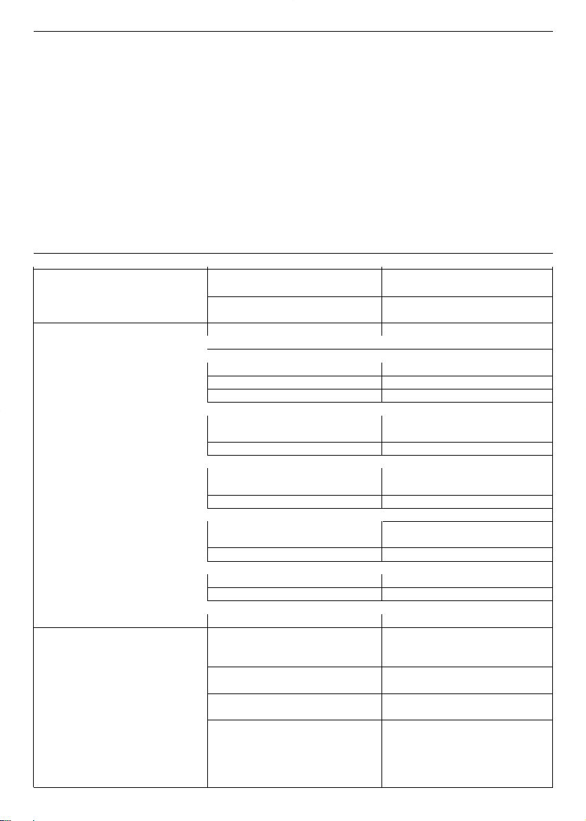
4.Limiti d’impiego
Per immagazzinamento :
• Temperatura ambiente da -5°C a +40°C .
Per l’utilizzo :
Fate riferimento ai manuali specifici per le informazioni riguardanti le elettropompe.
8
9
it
4.1 Sistema TKS (TEKNOSPEED installato sulla elettropompa)
Non usate il prodotto in ambienti con presenza di polveri, acidi, gas corrosivi e/o
infiammabili, ecc.
Non usate l’elettropompa per pompare liquidi pericolosi o infiammabili.
• Temperatura ambiente : da +0°C a +40°C
• Umidità relativa massima : 50 % a + 40°C purché non vi siano fenomeni di condensazione
• Altitudine massima sopra il livello del mare : 1000 metri
• Grado di protezione : IP 55 (se installato su motori con grado IP 55 o superiore)
• Pressione massima d’esercizio : fate riferimento allo specifico manuale d’uso dell’elettropompa
La versione di serie prevede la fornitura di un trasmettitore con fondo scala di 10 bar
(capitolo 4.2)
• Temperatura liquido pompato : da + 1°C a + 40 °C
• Natura liquido pompato : acqua priva di sostanze chimicamente aggressive e di solidi in
sospensione
• Potenza massima nominale dell’elettropompa abbinabile al convertitore : 1,1 kW
• Tensione di alimentazione del convertitore : 1 x 230 V ± 10 % 50/60 Hz
• Tensione di uscita dal convertitore (corrisponde alla tensione di alimentazione del motore):
3 x 230 V ±10 % 12-50 Hz (valori variabili secondo la curva tensione/frequenza del convertitore)
• Corrente nominale in ingresso al convertitore : 6,8 A
• Corrente nominale in uscita dal convertitore : 4,6 A
• Massimo numero di avviamenti orari, equamente distribuiti : leggete il manuale d’uso
dell’elettropompa
4.2 Trasmettitore di pressione
Il sensore di questo trasmettitore è un elemento di silicio piezoresistivo sensibile alla pressione, montato
su un piccolo circuito stampato flessibile (TAB) e immerso in una camera d’olio. La pressione viene trasmessa all’elemento attraverso una membrana d’acciaio situata nella camera d’olio.
• Campo di pressione : da 0 a 10 bar
• Alimentazione : 21 Vcc dal TEKNOSPEED
• Segnale in uscita : da 4 a 20 mA
• Connessione : 1/4“ maschio, in ottone nichelato
• Connettore elettrico : del tipo estraibile , fornito con due metri di cavo schermato
• Grado di protezione : IP 55
Per condizioni ambientali diverse, contattate il nostro Servizio di Vendita ed Assistenza.
5. Installazione Informazioni per l’installatore
Le operazioni d’installazione devono essere eseguite esclusivamente da personale esperto
e qualificato.
Usate le idonee attrezzature e protezioni. Seguite le norme di antinfortunistica.
Leggete questo manuale d’uso e quello dell’elettropompa prima dell’installazione.
Nel caso il prodotto presenti segni evidenti di danneggiamento non procedete con l’installazione e contattate il Servizio di Assistenza.
Installate il prodotto in un luogo protetto dal gelo e dalle intemperie, rispettando i limiti di impiego
e in modo da garantire il sufficiente raffreddamento del motore. Per ulteriori informazioni fate riferimento ai capitoli 4 e 12.
Osservate scrupolosamente le norme vigenti di sicurezza e antinfortunistica.

10
it
6. Messa in funzione
Informazioni per l’installatore
Le operazioni di messa in funzione devono essere eseguite esclusivamente da personale esperto
e qualificato. Usate le idonee attrezzature e protezioni. Seguite le norme di antinfortunistica.
Leggete questo manuale d’uso e quello della elettropompa prima della messa in funzione.
6.1 Allacciamento idraulico della elettropompa
Procedete ai collegamenti idraulici secondo le norme e leggi vigenti.
Il prodotto può essere utilizzato con il collegamento diretto dell’impianto all’acquedotto oppure prelevando l’acqua da un serbatoio di prima raccolta.
In caso di collegamento all’acquedotto seguite le disposizioni vigenti emanate dagli enti responsabili
(Comune, società erogatrice,…..). Si consiglia di installare un pressostato sul lato aspirazione per la disattivazione della elettropompa in caso di bassa pressione nell’acquedotto (protezione contro la marcia a
secco).
Verificate che la somma tra la pressione dell’acquedotto e la pressione massima della pompa
non superi il valore della pressione massima di lavoro consentita (pressione nominale PN) della
pompa medesima.
Se ad esempio nel sistema è presente una pompa CA 70/33 si ricava che :
Prevalenza massima della pompa :
43 metri (equivalenti ad una pressione di chiusura di 4,3 bar circa)
Pressione massima di lavoro consentita :
8 bar (PN 8)
Pressione dell’acquedotto (considerate il valore massimo):
1,5 bar
Pressione massima di lavoro risultante :
4,3 + 1,5 = 5,8 inferiore al limite di 8 bar
Se si utilizza un serbatoio di prima raccolta è necessario installare un galleggiante per la disattivazione
della elettropompa in caso di mancanza d’acqua (protezione contro la marcia a secco).
Dovete installare obbligatoriamente un manometro sul lato mandata poiché potrebbe rendersi
necessario modificare il valore di taratura di fabbrica a seconda delle reali condizioni di installa-
zione.
Normalmente l’impianto si completa con l’installazione di tubi flessibili su aspirazione e mandata, valvole
di intercettazione su aspirazione e mandata, valvola di non ritorno, autoclave a membrana. Nel caso
vogliate evitare di dover svuotare l’impianto per una eventuale sostituzione dell’autoclave a membrana o
del manometro oppure del trasmettitore di pressione, si consiglia l’installazione di valvole di intercettazione.
Nel caso di installazione della valvola di ritegno sul lato mandata della pompa, ponete il trasmettitore di
pressione a valle della valvola. Si consiglia l’installazione di un rubinetto da usarsi nella fase di taratura
del sistema TKS (capitolo 6.3.3) se non è già presente un punto di prelievo in prossimità alla pompa.
Per ulteriori informazioni fate riferimento al capitolo 12.
6.1.1 Serbatoio a pressione (autoclave a membrana)
Sul lato di mandata dell’elettropompa è necessario installare un autoclave a membrana per mantenere in
pressione l’impianto in assenza di richiesta d’acqua onde evitare il funzionamento continuo della pompa.
Col convertitore TEKNOSPEED non è necessario un autoclave di grande volume poiché è sufficiente che
il suo volume nominale, in litri, sia pari almeno al 5% della massima portata (litri al minuto) della pompa
con un minimo di 8 litri di capacità nominale.
Esempio : portata massima della pompa = 60 litri al minuto
volume nominale serbatoio = 60 x 0,05 = 3 litri ➞ 8 litri
portata massima della pompa = 150 litri al minuto
volume nominale serbatoio = 150 x 0,05 = 7,5 litri ➞ 8 litri
11
it
Assicuratevi che l’autoclave sia in grado di sopportare la pressione massima dell’impianto.
Controllate e regolate la corretta pressione di precarica prima del collegamento dell’autoclave all’impianto.
Se l’autoclave fosse già stato collegato, è necessario svuotare l’impianto prima di controllare e regolare
la pressione di precarica. Per evitare questo, si consiglia di installare una valvola d’intercettazione tra il
collegamento all’autoclave e la tubazione dell’impianto.
Per determinare il valore della precarica dell’autoclave potete utilizzare la seguente formula :
se in bar ➞ pressione di lavoro – 0,2 = pressione di precarica
se in kPa ➞ pressione di lavoro – 20 = pressione di precarica
6.2 Allacciamento elettrico dell’elettropompa
Procedete ai collegamenti elettrici secondo le norme e leggi vigenti.
Controllate che il tipo di rete, la tensione e la frequenza di alimentazione coincidano con i dati no-
minali del sistema TKS riportati nella targa dati. Assicurate una idonea protezione generale dal
cortocircuito sulla linea elettrica.
ATTENZIONE : pur avendo il sistema TKS una alimentazione monofase, il motore della pompa è sempre
un trifase collegato a 230 V. Le fasi mancanti vengono create dal convertitore. Per ulteriori informazioni
fate riferimento al capitolo 12.
Prima di eseguire lavori accertarsi che tutti i collegamenti (anche quelli liberi da potenziale )
siano privi di tensione. Scollegate sempre il convertitore TEKNOSPEED dall’alimentazione elet-
trica prima di effettuare qualsiasi operazione sulle parti elettriche o meccaniche dell’impianto.
Attendete almeno 1 minuto dopo il disinserimento dalla rete prima di effettuare interventi sul TEK-
NOSPEED affinché i condensatori del circuito interno possano scaricarsi.
6.2.1 Interruttore magnetotermico differenziale
Se previsto dalle normative elettriche locali vigenti l’installazione di un interruttore magnetotermico differenziale, assicuratevi che sia del tipo idoneo all’installazione. Gli interruttori adatti sono quelli aventi la
curva caratteristica per correnti di guasto alternate e pulsanti unidirezionali (tipo A oppure C).
Possono essere distinguibili tramite la presenza del seguente simbolo:
6.2.2 Versione con cavo e spina
ll sistema TKS è fornito col cavo d’alimentazione avente la spina.
Installate la pompa in modo da rendere sempre bene accessibile la spina e relativa presa nell'e-
ventualità che si rendesse necessario disattivare il sistema.
In caso di danneggiamento del cavo di alimentazione, la sostituzione deve essere eseguita presso un
centro di assistenza o comunque da personale qualificato.
6.2.3 Filtro di ingresso
Il convertitore TEKNOSPEED ha un filtro di ingresso e risulta conforme alla direttiva EMC.
6.2.4 Protezione dal sovraccarico del motore
Il convertitore TEKNOSPEED ha una protezione da sovraccarico incorporata che garantisce l’assoluta
protezione quando è abbinato a motori aventi una potenza nominale pari a quella del convertitore. Per
motori di potenza inferiore si usa una protezione supplementare (capitolo 6.2.5)
6.2.5 Protezione dalla sovratemperatura del motore (PTC)
In alcuni modelli di motori può essere presente una protezione (termistore) che si aggiunge a quella da
sovraccarico incorporata nel convertitore. Il termistore (PTC) è fissato sulla base della morsettiera e collegato alla scheda di comando tramite cavetti e minifaston. Il relativo dip-switch risulterà in posizione
PTC Y. Per ulteriori informazioni fate riferimento al capitolo 12.
6.2.6 Protezione dalla sovratemperatura del convertitore
Il convertitore TEKNOSPEED ha una protezione da sovratemperatura incorporata.
12
it
6.2.7 Protezione contro la marcia a secco (galleggiante)
Il convertitore TEKNOSPEED ha la possibilità di essere collegato ad un dispositivo esterno per la protezione contro la marcia a secco della pompa (capitolo 6.1). Il metodo più tradizionale prevede l’uso di un
galleggiante posto nella vasca di aspirazione.
Per collegare il cavo del dispositivo esterno dovete togliere il radiatore del convertitore usando una chiave a brugola n.5 (coppia massima 6 Nm). Capovolgete il radiatore facendo attenzione ai collegamenti
con la morsettiera estraibile. Potrebbe rendersi necessario estrarre la morsettiera. Sostituite un tappo M
16 x 1.5 con uno dei pressacavi in dotazione. Fate passare il cavo del galleggiante e collegatelo ai mor-
setti corrispondenti a LOW 1 e LOW 2 (adatti per conduttori da 0,5÷1 mm2). Avvitate la piastrina serracavo e stringete il pressacavo per bloccare il cavo. Potete utilizzare un pressostato che apra il suo contatto quando la pressione scende sotto il valore di taratura nel caso colleghiate l’aspirazione della pompa
all’acquedotto.
Se non usate alcun dispositivo lasciate i due morsetti ponticellati.
Utilizzate il cacciavite a lama piatta (2,5 mm) in dotazione al sistema TKS per i collegamenti sulla
morsettiera del convertitore.
Per ulteriori informazioni fate riferimento al capitolo 12.
6.2.8 Abilitazione esterna
Potete collegare un interruttore al posto del galleggiante (capitolo 6.2.7). Con questo dispositivo esterno
potrete abilitare o disabilitare il sistema. Si consiglia l’uso di un cavo schermato . La spelatura del cavo
deve essere tale che relativa schermatura risulti in contatto con la piastrina serracavo.
Utilizzate il cacciavite a lama piatta (2,5 mm) in dotazione al sistema TKS per i collegamenti sulla
morsettiera del convertitore
Per ulteriori informazioni fate riferimento al capitolo 12.
6.2.9 Relè di allarme
Il convertitore TEKNOSPEED ha un contatto disponibile per ottenere una segnalazione esterna di blocco
o anomalia.
Questo contatto risulta chiuso se
• la pompa è ferma per una delle seguenti cause: mancanza di tensione
sovraccarico del motore (capitolo 6.2.5)
sovratemperatura del motore (capitolo 6.2.6)
sovratemperatura del convertitore (capitolo 6.2.7)
sensore guasto o non collegato (capitolo 6.2.11)
• manca acqua in aspirazione (capitoli 6.2.8 e 6.2.9)
Per collegare il cavo dovete togliere il radiatore del convertitore usando una chiave a brugola n.5 (coppia
massima 6 Nm). Capovolgete il radiatore facendo attenzione ai collegamenti con la morsettiera estraibile. Potrebbe rendersi necessario estrarre la morsettiera. Sostituite un tappo M 16 x 1.5 con uno dei
pressacavi in dotazione. Fate passare il cavo e collegatelo ai morsetti corrispondenti a COM e NC (adatti per conduttori da 0,5÷1 mm
2
). Avvitate la piastrina serracavo e stringete il pressacavo per bloccare
il cavo.
Si consiglia l’uso di un cavo schermato . La spelatura del cavo deve essere tale che relativa schermatura risulti in contatto con la piastrina serracavo.
Utilizzate il cacciavite a lama piatta (2,5 mm) in dotazione al sistema TKS per i collegamenti sulla
morsettiera del convertitore
Per ulteriori informazioni fate riferimento al capitolo 12.
6.2.10 Interfaccia seriale
Il convertitore TEKNOSPEED ha una interfaccia seriale utilizzabile solo nei sistemi di pompaggio con due
pompe.
Non collegate fili ai morsetti COM, TX, RX dell’interfaccia seriale.
Per ulteriori informazioni fate riferimento al capitolo 12.
13
it
6.2.11 Trasmettitore di pressione
Il sistema TKS viene fornito col trasmettitore di pressione collegato alla morsettiera del convertitore
TEKNOSPEED.
Il trasmettitore ha un cavo schermato lungo 2 metri. Nel caso dobbiate avvolgere il cavo, non arrotolatelo ma piegatelo a fisarmonica.
Per ulteriori informazioni fate riferimento al capitolo 12.
6.2.12 Dip-switch di regolazione
Il convertitore TEKNOSPEED ha una serie di microinterruttori (dip-switch) che ne determinano il ciclo di
funzionamento.
Non modificate l’impostazione di fabbrica. Potreste danneggiare il sistema o l’impianto ove il sistema è installato.
Per ulteriori informazioni fate riferimento al capitolo 12.
6.3 Primo avviamento
6.3.1 Adescamento
Leggete il manuale d’uso della elettropompa.
Riempite d’acqua la pompa e la tubazioni di aspirazione prima di avviare il sistema. Il funzionamento a secco può danneggiare la pompa.
Avviate il sistema con la valvola di intercettazione in mandata chiusa. Poi apritela gradualmente.
Quando l’aria presente nella tubazione sarà stata espulsa la pompa avrà un funzionamento regolare e silenzioso.
6.3.2 Verifica del senso di rotazione del motore
Non è necessario che procediate alla verifica del senso di rotazione poiché già predeterminato in fabbrica.
6.3.3 Taratura della pressione di lavoro
Dovete installare obbligatoriamente un manometro sul lato mandata poiché potrebbe rendersi
necessario modificare il valore di taratura di fabbrica a seconda delle reali condizioni di installazione ed esigenze dell’impianto.
Il sistema TKS viene fornito già con una taratura di fabbrica che ne consente l’utilizzo.
Potete modificare il valore della pressione in base alle reali esigenze dell’impianto nel seguente modo :
• Aumento del valore della pressione
- Verificate che l’impianto sia in pressione, nessuna utenza sia aperta e la pompa sia ferma. Nel caso
qualche utenza fosse aperta potete chiudere la valvola di intercettazione posta a valle della pompa.
- Svitate il tappo che protegge la vite di regolazione
- Ruotate lentamente verso destra la vite di regolazione usando un cacciavite.
Utilizzate il cacciavite a lama piatta (2,5 mm) in dotazione al sistema TKS. La vite di regolazione ha una corsa limitata, inferiore ad un giro, tra il valore minimo (0 bar) ed il valore massimo (10
bar). Non forzate oltre i limiti poiché potete danneggiare la vite di regolazione.
- La pompa si avvia.
- Leggete il valore della pressione sul manometro e continuate a ruotare la vite di regolazione finché la
lancetta del manometro non avrà raggiunto il valore desiderato.
- Assicuratevi che la pressione si sia stabilizzata al valore desiderato.
- Se necessario eseguite lievi variazioni ruotando a destra o a sinistra la vite di regolazione. Se dovete
ridurre la pressione di taratura, si consiglia di aprire leggermente una utenza (vedere sezione successiva “Diminuzione del valore della pressione”).
Assicuratevi che il nuovo il valore scelto sia compreso nel campo della prevalenza indicata nella
targa dati del sistema TKS.
- La pompa si ferma dopo circa 60 secondi. La pressione di fermata potrebbe essere leggermente su-
periore al valore desiderato (capitolo 6.4.1)
14
it
• Diminuzione del valore della pressione
- Verificate che l’impianto sia in pressione, nessuna utenza sia aperta e la pompa sia ferma.
- Svitate il tappo che protegge la vite di regolazione
- Lasciate aperta la valvola di intercettazione posta a valle della pompa
- Aprite leggermente una utenza oppure il rubinetto di prova (capitolo 6.1) facendo scendere la pressio-
ne lentamente
- La pompa si avvia.
- Ruotate lentamente verso sinistra la vite di regolazione usando un cacciavite.
Utilizzate il cacciavite a lama piatta (2,5 mm) in dotazione al sistema TKS. La vite di regolazione ha una corsa limitata, inferiore ad un giro, tra il valore minimo (0 bar) ed il valore massimo (10
bar). Non forzate oltre i limiti poiché potete danneggiare la vite di regolazione.
- Leggete il valore della pressione sul manometro e continuate a ruotare la vite di regolazione finché la
lancetta del manometro non avrà raggiunto il valore desiderato.
- Assicuratevi che la pressione si sia stabilizzata al valore desiderato.
- Se necessario eseguite lievi variazioni ruotando a destra o a sinistra la vite di regolazione
Assicuratevi che il nuovo il valore scelto sia compreso nel campo della prevalenza indicata nella
targa dati del sistema TKS.
- La pompa si ferma dopo circa 60 secondi. La pressione di fermata potrebbe essere leggermente su-
periore al valore desiderato (capitolo 6.4.1)
Per ulteriori informazioni fate riferimento al capitolo 12.
6.3.4 Indicazioni luminose
Sull’adesivo posto sopra al radiatore sono presenti tre led luminosi con le seguenti funzioni :
Luce verde persistente Power Indica la presenza di tensione al sistema TKS
Luce gialla persistente Run Indica la pompa in funzione
Luce rossa lampeggiante Alarm Indica uno stato di allarme
In caso di allarme la luce rossa lampeggerà con frequenza variabile a seconda della causa del blocco
del sistema. Tranne per la mancanza d’acqua in aspirazione, in tutti gli altri casi il sistema si riavvia automaticamente dopo 20 secondi. Se persiste la causa dell’anomalia, dopo tre tentativi di avvio il sistema va
in blocco definitivamente, tranne per la mancanza d’acqua in aspirazione.
Per ulteriori informazioni fate riferimento ai capitoli 8.1 e 12.
6.4 Descrizione del prodotto Informazioni per l’utilizzatore
Il sistema TKS è composto da una elettropompa azionata tramite un sistema di controllo automatico elettronico (convertitore di frequenza conosciuto anche come variatore di giri) che consente di erogare una
pressione costante riducendo o aumentando la portata in base alle richieste.
6.4.1 Funzionamento
Il sistema di controllo automatico elettronico prende il segnale proveniente da un sensore di pressione e
lo confronta con il valore impostato.
Con l’impianto in pressione la pompa è ferma. L'abbassamento della pressione, determinato dal prelievo di acqua da parte dell'utenza, provoca la riduzione del segnale che, attraverso il sistema di controllo,
fa avviare la pompa regolandone la velocità in modo che venga ristabilita la pressione di riferimento (o di
lavoro). Se il prelievo d’acqua aumenta il sistema di controllo fa aumentare la velocità, se il prelievo diminuisce il sistema di controllo fa diminuire la velocità della pompa. Al raggiungimento della massima
portata d’acqua erogabile dalla pompa il sistema di controllo fa lavorare la pompa alla sua massima velocità nominale.
In caso di aumento della pressione, determinato da una riduzione del prelievo di acqua, aumenta il segnale proveniente dal sensore che, attraverso il sistema di controllo, fa ridurre la velocità della pompa.
Se l’interruzione del prelievo d’acqua avviene bruscamente (ad esempio rapida chiusura dei rubinetti), il
sistema di controllo fa funzionare la pompa ad una velocità minima per poi fermarla dopo circa 60 secon-
di. In questo caso la pressione di fermata coincide col valore impostato.
Se l’interruzione avviene lentamente, il sistema fa funzionare la pompa ad una pressione leggermente su-
periore (con fondo scala trasmettitore uguale a 10 bar ➞ + 0,2 bar) per poi fermarla dopo circa 60 secondi se non vi sono prelievi d’acqua.
In caso di presenza di tensione risulta accesa la luce di colore verde (Power).
Quando la pompa è in funzione risulta accesa la luce di colore giallo (Run).
In caso di blocco o funzionamento anomalo risulta accesa la luce di colore rosso (Alarm).
In caso di allarme la luce rossa lampeggerà con frequenza variabile a seconda della causa del blocco
del sistema. Tranne per la mancanza d’acqua in aspirazione, in tutti gli altri casi il sistema si riavvia automaticamente dopo 20 secondi. Nel caso persista la causa dell’anomalia, dopo tre tentativi di avvio il sistema va in blocco definitivamente.
Per qualsiasi necessità di intervento di regolazione e/o manutenzione rivolgetevi a personale
esperto e qualificato. Non provate a cambiare le regolazioni né ad aprire il sistema di controllo.
Leggete i manuali prima dell’uso e conservateli con cura.
Conservate con cura il cacciavite fornito col sistema TKS.
7. Manutenzione Informazioni per il manutentore
Attenersi alle seguenti regole se si rendesse necessario intervenire sul prodotto.
Interventi di manutenzione devono essere eseguiti solo da personale qualificato.
Prima di eseguire lavori accertatevi che tutti i collegamenti (anche quelli liberi da potenziale)
siano privi di tensione.
Scollegate sempre il convertitore TEKNOSPEED dall’alimentazione elettrica prima di effettuare
qualsiasi operazione sulle parti elettriche o meccaniche dell’impianto.
Attendete almeno un minuto dopo il disinserimento dalla rete prima di effettuare interventi sul
TEKNOSPEED affinché i condensatori del circuito interno possano scaricarsi.
Leggete il presente manuale d’uso nonchè quelli dell’elettropompa e dell’eventuale autoclave a
membrana.
7.1 Manutenzione ordinaria
Il sistema TKS non ha bisogno di alcuna manutenzione ordinaria se impiegato nei limiti previsti al capitolo 4.
Le pompe non hanno bisogno di alcuna manutenzione ordinaria (leggete il manuale della pompa).
Controllate la precarica d’aria dell’autoclave, se presente, almeno una volta all’anno (capitolo 6.1.1).
7.2 Manutenzione straordinaria
Usate le idonee attrezzature e protezioni. Seguite le norme di antinfortunistica. Sollevate e movimentate le pompe con cura utilizzando idonei apparecchi di sollevamento
Usate solo ricambi originali per sostituire gli eventuali componenti guasti.
ATTENZIONE !
Pur avendo il sistema TKS una alimentazione monofase, il motore della pompa è sempre un trifase collegato a 230 V. Le fasi mancanti vengono create dal convertitore. Per ulteriori informazioni fate riferimento
al capitolo 12.
15
it
16
it
8. Ricerca guasti
Informazioni per l’utilizzatore e il manutentore
Leggete il presente manuale d’uso nonchè quelli dell’elettropompa e dell’eventuale autoclave a
membrana.
Eventuali interventi devono essere eseguiti solo da personale qualificato.
Per ulteriori informazioni fate riferimento ai capitoli 7 e 12.
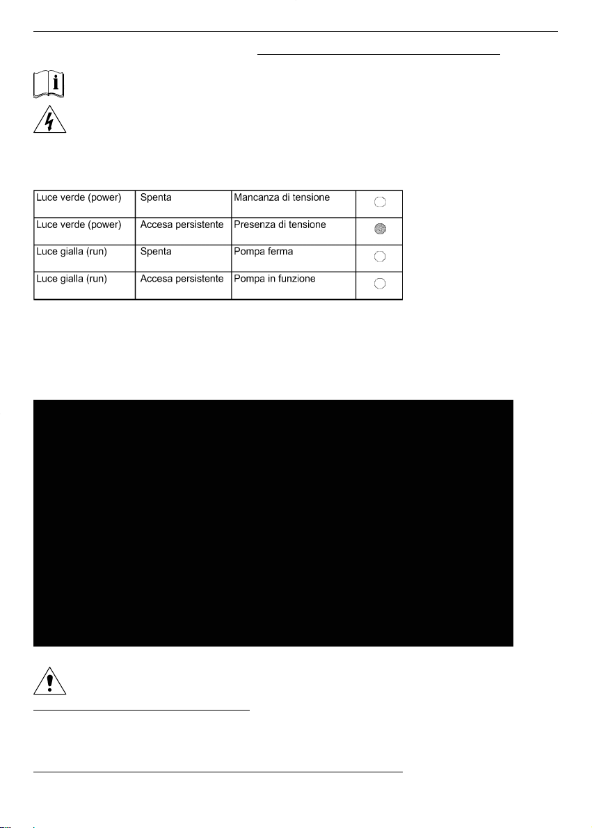
8.1 Segnalazioni luminose
8.1.1 Segnalazioni di funzionamento
Queste segnalazioni essenziali vengono integrate da quelle di allarme. Pertanto si potrebbero avere
combinazioni di segnalazioni come la luce verde accesa (presenza di tensione), la luce gialla spenta
(pompa ferma) e la luce rossa lampeggiante (allarme).
8.1.2 Segnalazioni di allarme
In caso di allarme la luce rossa lampeggerà con frequenza variabile (lampeggi – pausa – lampeggi) a
seconda della causa del blocco del sistema.
Fate attenzione quando intervenite sul sistema poiché potrebbe riavviarsi automaticamente.
Blocco per mancanza acqua in aspirazione
In presenza di blocco per la mancanza d’acqua in aspirazione, il sistema si riavvia automaticamente solo
se il dispositivo esterno riabilita il funzionamento (galleggiante o pressostato o interruttore ➞ capitoli
6.2.7 e 6.2.8).
Blocco per altri motivi ad esclusione della mancanza acqua in aspirazione
In tutti questi casi il sistema si riavvia automaticamente dopo 20 secondi. Se persiste la causa dell’ano-
TKS_M0025_A_OT.XLS
TKS_M0026_A_OT.XLS
17
it
malia, dopo tre tentativi di avvio il sistema va in blocco definitivamente.
Per riazzerare la situazione dovete togliere la tensione al sistema per almeno un minuto.
Se dopo un allarme trascorrono almeno 10 minuti senza alcuna altra anomalia, il contatore di allarmi
viene azzerato e sono possibili nuovamente tre tentativi.
Nel caso di due o più cause di allarme simultanee (ad esempio sovratemperatura motore e mancanza
acqua), viene segnalata sempre e solo la prima che riesce a far giungere il segnale alla scheda di controllo.
ATTENZIONE ! Il convertitore non ha una memoria indelebile degli allarmi attivati. Pertanto si consi-
glia di osservare con cura la frequenza di lampeggio prima di togliere la tensione al
sistema TKS
Per ulteriori informazioni fate riferimento ai capitoli 8.1 e 12.
8.2 Guida
INCONVENIENTE PROBABILE CAUSA POSSIBILE RIMEDIO
L'elettropompa non si avvia Mancanza di alimentazione Ripristinate l'alimentazione
L'interruttore generale è inserito elettrica
Luce verde spenta Scattato l'interruttore Riarmare l'interruttore
magnetotermico
L'elettropompa non si avvia oppure
si ferma se già in funzione *** = 2 lampeggi
L'interruttore generale è inserito Sovraccarico del motore Verificate le condizioni di lavoro
Luce verde accesa dell'elettropompa
Luce rossa accesa (*** lampeggi) Statore del motore danneggiato Controllate il motore
*** = 3 lampeggi
Sovratemperatura del convertitore Controllate che nulla impedisca il
corretto raffreddamento del
convertitore
*** = 4 lampeggi
Sovratemperatura del motore (se Verificate le condizioni di lavoro
presente la protezione PTC nella dell'elettropompa
morsettiera)
*** = 5 lampeggi
Eventuale protezione contro la Controllate il livello dell'acqua
marcia a secco intervenuta Controllate il dispositivo esterno e
i relativi cavi di collegamento
*** = 6 lampeggi
Problemi sul trasmettitore di Controllare il trasmettitore e il
pressione relativo cavo di collegamento
*** = 7 lampeggi
La tensione di alimentazione è
troppo bassa
Utenze chiuse Perdite d'acqua attraverso la valvola Controllate l'impianto per localizzare
Elettropompa in funzione con di non ritorno o nell'impianto le perdite. Riparate o sostituite i
aumento e diminuzione ciclica componenti.
della velocità Eventuale autoclave sottodimensio-Verificate le condizioni di lavoro
Luce verde accesa nato dell'elettropompa
Luce gialla accesa Eventuale autoclave con la Sostituite la membrana
Luce rossa spenta membrana rotta
Taratura del punto di lavoro Ritarate il sistema
non adatta all'impianto (valore
più alto della pressione erogabile
dalla pompa)
Utenze aperte Taratura del punto di lavoro Ritarate il sistema
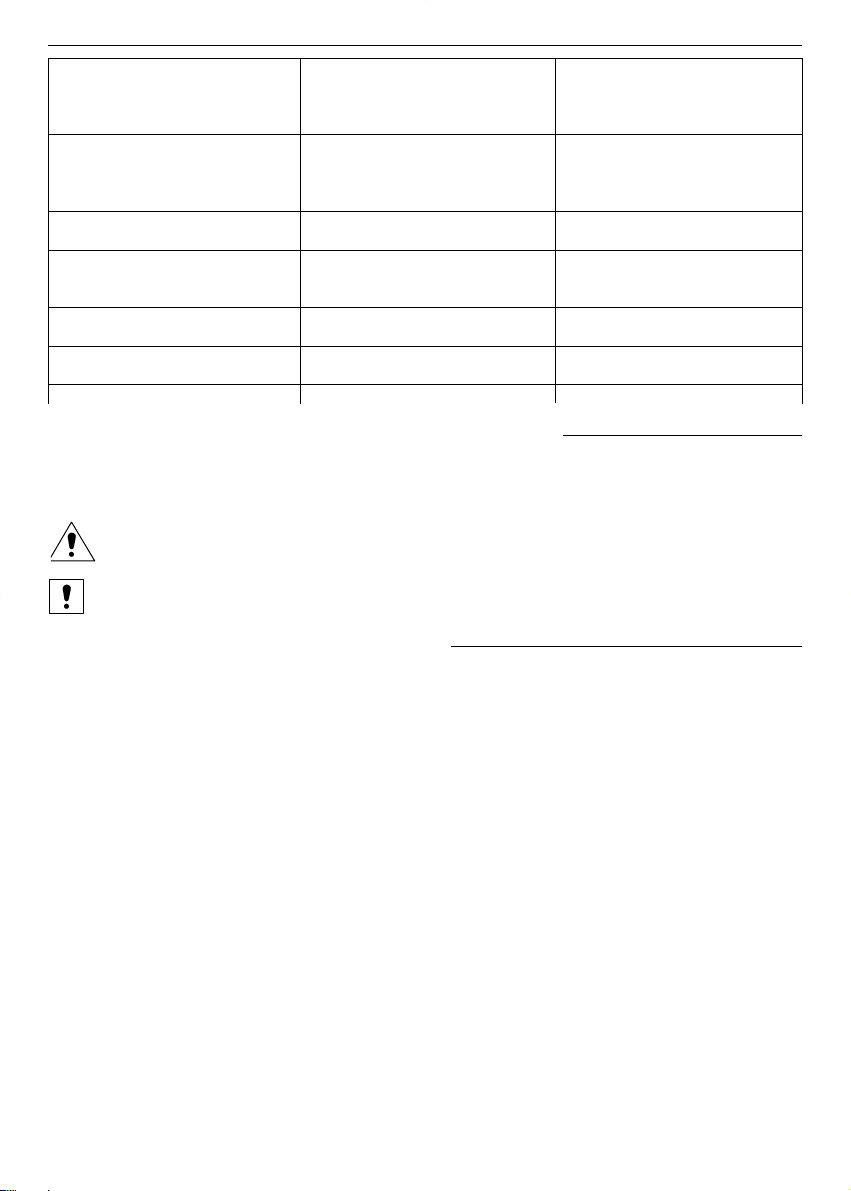
L'elettropompa non si avvia non adatta all'impianto (valore
Luce verde accesa pari a zero)
Luce gialla spenta
Luce rossa spenta
L'elettropompa è in funzione Taratura del punto di lavoro Ritarate il sistema
Presenza di vibrazioni nella non adatta all'impianto (valore
pompa o in prossimità della inferiore alla pressione minima
pompa erogabile dalla pompa)
L'elettropompa è in funzione Possibili problemi al galleggiante Controllate il galleggiante e la
Frequenti avvii e fermate posto nella vasca di aspirazione vasca
L'elettropompa è in funzione Possibili problemi sul trasmettitore Controllare il collegamento
sempre alla massima velocità di pressione idraulico tra il trasmettitore e
l'impianto
Interviene la protezione generale Corto circuito Verificate i cavi di collegamento
dell’impianto
Interviene la protezione differenziale Dispersione a terra Verificare l’isolamento
dell’impianto ("Salvavita") dell’elettropompa e dei cavi
9. Ricambi Informazioni per il manutentore
Precisare sempre l’esatta sigla di identificazione del modello, unitamente al numero di costruzione, qualora debbano essere richieste informazioni tecniche o particolari di ricambio al nostro Servizio di Vendita
ed Assistenza.
Usate solo ricambi originali per sostituire gli eventuali componenti guasti.
L’utilizzo di parti di ricambio non adatte può provocare funzionamenti anomali e pericoli per le
persone e le cose.
10. Smaltimento Informazioni per l’installatore e il manutentore
Dopo l’installazione smaltire l’imballo secondo le leggi vigenti, se possibile riutilizzare l’imballo per altri
usi.
Se si dovesse ricorrere alla dismissione del motore e quindi al suo smontaggio si devono rispettare le
leggi vigenti per lo smaltimento differenziato dei rifiuti.
11. Garanzia
Per qualsiasi informazione fate riferimento alla documentazione contrattuale di vendita.
18
it
English
« Translation of the original instructions »
en
1. Overview
The purpose of this manual is to provide the necessary information for proper installation, operation
and maintenance of the TEKNOSPEED converter connected to a LOWARA electric pump.
Read this manual before using the product.
Improper use may cause personal injury and damage to property, and lead to the forfeiture of the
warranty coverage.
For information regarding the electric pumps, refer to the relevant manuals.
The instructions and warnings provided below concern the standard version.
Please refer to the sale contract for any modifications or special version characteristics.
Always specify the exact model identification code and construction number when requesting technical
information or spare parts from our Sales and Service department.
For instructions, situations or events not considered in this manual or in the sale documents, please contact our Service Center nearest you.
2. Preliminary Inspection
2.1 Visual Inspection
Upon delivery, check the integrity of the packaging.
If the packaging is damaged, unpack the product and inspect it visually to make sure it has suffered no
damage during transport.
Should the product be damaged, inform our dealer within 8 days from delivery.
2.2 Handling and Storage
The product is delivered in a cardboard box or wooden case. During transport and storage, protect it
from humidity, heat sources and possible mechanical damage (impacts, falls, etc). Lift and handle the
product carefully using suitable hoisting equipment.
Refer to chapter 4 for further information.
3. Applications
The TKS system consists of a three-phase electric pump, the TEKNOSPEED single-phase converter and
an electronic pressure transmitter (also known as pressure sensor).
The TEKNOSPEED single-phase converter is suitable for the control of a three-phase electric pump according to the conditions described in this manual and the supply voltage / frequency specified in the rating plate.
The converter controls the operation of the pump in order to ensure a constant delivery pressure based
on the signal received from the electronic pressure transmitter.
The TKS system can be used for domestic water supply, irrigation and pressure boosting applications.
For further information refer to chapter 12.
4. Working Limits
For storage :
• Ambient temperature: -5°C to +40°C .
For operation :
For information regarding electric pumps refer to the relevant manuals.
19

4.1 TKS system (TEKNOSPEED mounted on the electric pump)
Do not use the product in environments where corrosive and/or flammable powders, acids,
gases, etc. are present.
Do not use the electric pump to handle dangerous or flammable liquids.
• Ambient temperature: +0°C to +40°C
• Maximum relative humidity : 50 % at + 40°C provided no condensation occurs
• Maximum height above sea level: 1000 meters
• Protection class : IP 55 (if installed on motors with at least IP55 protection)
• Maximum operating pressure : refer to the operating instructions for the electric pump
The standard version features a transmitter with 10 bar full scale (chapter 4.2)
• Temperature of pumped liquid : + 1°C to + 40 °C
• Nature of pumped liquid : water containing no chemically aggressive substances or
suspended solids
• Maximum rated power of electric pump connected to the converter : 1.1 kW
• Converter supply voltage : 1 x 230 V ± 10 % 50/60 Hz
• Converter output voltage (corresponding to the motor supply voltage) :
3 x 230 V ± 10 % 12-50 Hz (these values vary according to the converter’s
voltage/frequency curve)
• Converter’s rated input current : 6.8 A
• Converter’s rated output current: 4.6 A
• Maximum number of starts per hour, evenly distributed : read the operating instructions for
the electric pump
4.2 Pressure transmitter
The sensor for this transmitter is a piezo-resistive silicon element which is sensitive to pressure. It is
mounted on a small flexible printed circuit (TAB) and is immersed in an oil chamber. The pressure is transmitted to the sensor through a steel diaphragm located in the oil chamber.
• Pressure range : 0 to 10 bar
• Power supply : 21 Vdc from TEKNOSPEED
• Output signal : 4 to 20 mA
• Connection :
1
/4
” male, made of nickel plated brass
• Electrical connector : removable, provided with 2-meter shielded cable
• Protection class : IP 55
For ambient conditions other than those specified above, please contact our Sales and Service
Department.
5. Installation Information for installers
The installation operations must be carried out by skilled and qualified personnel.
Use adequate equipment and protections. Observe the accident prevention regulations in force.
Before proceeding with the installation, read these operating instructions and the manual for the
electric pump.
If the product shows evident signs of damage, do not proceed with installation but contact our Customer
Service Center.
Install the product in a sheltered location protected from the weather and freezing temperatures;
observe the working limits in order to guarantee adequate motor cooling. For further information
refer to chapters 4 and 12.
Observe all the safety standards and accident prevention regulations in force.
20
en
6. Start-up
Information for installers
The start-up operations must be performed by skilled and qualified personnel. Use adequate
equipment and protections. Observe the accident prevention regulations in force.
Before starting the unit, read these operating instructions and the manual for the electric pump.
6.1 Hydraulic Connection of Electric Pump
The hydraulic connections must comply with current standards and legislation.
The product can be connected directly to the municipal water system or the water can be taken from a
storage tank.
In case of connection to the municipal water system follow the regulations locally in force (issued by City,
utility company, etc.). We suggest that you install a pressure switch on the suction side for deactivation
of the electric pump in the event of low water system pressure (protection against dry running).
Make sure that the water system pressure added to the maximum pressure of the pump does not
exceed the maximum operating pressure value (nominal pressure NP) allowed for the pump.
For example, if the system features a CA 70/33 pump we can calculate that :
Maximum head of the pump :
43 meters (equivalent to a closing contact pressure of approximately 4.3 bar)
Maximum working pressure allowed :
8 bar (NP 8)
Water system pressure (consider the maximum value):
1.5 bar
Resulting maximum working pressure :
4.3 + 1.5 = 5.8 less than the 8 bar limit
When using a storage tank it is necessary to install a float switch for deactivation of the electric pump in
the event of low water (protection against dry running).
You must install a pressure gauge on the delivery side as it may be necessary to modify the fac-
tory settings based on the actual installation conditions.
To complete the system, flexible pipes on suction and delivery side, on-off valves on suction and delivery
side, non-return valve and surge tank with diaphragm are normally installed. To avoid having to drain the
system in the event that the diaphragm tank or the pressure gauge or the pressure transmitter need replacing, we advise you to install on-off valves.
If you install a check valve on the pump’s delivery side, position the pressure transmitter downstream
from the valve. We advise you to install a test tap to be used during the TKS system’s calibration stage
(chapter 6.3.3) unless a water drawing point is already present in the vicinity of the pump .
For further information refer to chapter 12.
6.1.1 Surge Tank (Diaphragm Tank)
A diaphragm tank must be installed on the delivery side of the electric pump to maintain pressure in the
system when there is no water demand, in order to prevent continuous pump operation.
With the TEKNOSPEED converter there is no need for a large capacity tank. The nominal capacity of the
tank, in liters, must be at least 5% of the maximum flow rate (liters per minute) of one pump, with a minimum of 8 liters of nominal capacity.
Example : maximum flow rate of pump = 60 liters per minute
nominal volume of tank = 60 x 0.05 = 3 liters ➞ 8 liters
maximum flow rate of pump = 150 liters per minute
nominal volume of tank = 150 x 0.05 = 7.5 liters ➞ 8 liters
21
en
Make sure that the surge tank can handle the maximum pressure of the system.
Check and adjust the precharge pressure before connecting the surge tank to the system.
If the surge tank is already connected, you will have to drain the system before you check and adjust the
precharge pressure. To avoid doing this, we suggest that you install an on-off valve between the connection to the tank and the system’s pipe.
To determine the precharge value for the surge tank you can use the following formula:
if in bar ➞ work pressure – 0.2 = precharge pressure
if in kPa ➞ work pressure – 20 = precharge pressure
6.2 Electrical Connection of Pump
The electrical connections must comply with current standards and regulations.
Make sure that the type of power source, the supply voltage and frequency match the ratings of
the TKS system shown in the rating plate. Provide suitable general protection against short cir-
cuits on the electrical power line.
WARNING : although the TKS system has single-phase power supply, the pump’s motor is always a
three-phase motor connected to 230 V. The missing phases are created by the converter. For further
information refer to chapter 12.
Before proceeding with these operations, make sure that all the connections (even those that are
potential-free) are voltage-free. Always disconnect the TEKNOSPEED converter from the power
supply before carrying out any operations on the system’s electrical or mechanical components.
After disconnection from the power source, wait at least 1 minute before carrying out any work on
TEKNOSPEED to allow the condensers in the internal circuit to discharge.
6.2.1 Differential Magneto-thermal Switch
If local regulations require the installation of a differential magneto-thermal switch, make sure it is of a
type that is suited to the system. Suitable switches are those having the characteristic curve for unidirectional alternate and pulsating DC fault current (type A or C).
They can be identified by the presence of the following symbol:
6.2.2 Version with Cable and Plug
The TKS system is equipped with power cord and plug.
When installing the pump, make sure that the plug and corresponding outlet are easily accessi-
ble in case the system needs to be deactivated.
If the power cord is damaged, it must be replaced at a service center or by qualified personnel.
6.2.3 Input Filter
The TEKNOSPEED converter is equipped with an input filter according to the EMC directive.
6.2.4 Motor Overload Protection
The TEKNOSPEED converter has an incorporated overload protection which guarantees absolute protection when it is connected to motors featuring the same nominal protection as that of the converter. For
lower power motors an auxiliary protection is used (see chapter 6.2.5)
6.2.5 Motor Overtemperature Protection (PTC)
Some models may feature an extra protection (thermistor) in addition to the overload protection incorporated in the converter. The thermistor (PTC) is attached to the base of the terminal board and connected
through cables and mini-fastons. The corresponding dip-switch will be in the PTC Y position.
For further information refer to chapter 12.
6.2.6 Converter overtemperature protection
The TEKNOSPEED converter has an incorporated overtemperature protection.
22
en
6.2.7 Protection against dry running (float switch)
The TEKNOSPEED converter can be connected to an external device for protection against pump dry
running (see chapter 6.1). The most conventional method consists in the use of a float switch installed in
the suction tank.
To connect the cable of the external device you must remove the converter’s radiator using a no. 5 Allen
wrench (maximum torque 6 Nm). Turn the radiator upside down, paying attention to the connections with
the removable terminal board. The terminal board may have to be extracted. Replace an M 16 x 1.5 plug
with one of the cable glands supplied. Lay the float switch cable and connect it to the terminals corre-
sponding to LOW 1 and LOW 2 (suitable for 0.5÷1 mm2conductors). Screw down the cable fastening
plate and tighten the cable gland to secure the cable. If you connect the suction side of the pump to the
municipal water system, you can use a pressure switch that opens its contact when the pressure drops
below the set point.
If you are not using any device, two terminals must be connected with a jumper.
Use the slotted blade screwdriver (2.5 mm) provided with the TKS system for the connections on
the converter’s terminal board.
For further information refer to chapter 12.
6.2.8 External Enable Device
You can connect a switch instead of the float switch (chapter 6.2.7). This external device can be used to
enable or disable the system. We recommend using a shielded cable. The stripping of the cable should
allow the shielding to be in contact with the cable fastening plate.
Use the slotted blade screwdriver (2.5 mm) provided with the TKS system for the connections on
the converter’s terminal board.
For further information refer to chapter 12.
6.2.9 Alarm Relay
The TEKNOSPEED converter has a contact that can be used to obtain an external shutdown or malfunction signal.
This contact is closed when
• the pump is not running due to one of the following causes : no voltage
motor overload (chapter 6.2.5)
motor overtermperature (chapter 6.2.6)
converter overtemperature (chapter 6.2.7)
Probe faulty or disconnected (chapter 6.2.11)
• lack of water on suction side (chapters 6.2.8 and 6.2.9)
To connect the cable you must first take the radiator off the converter using a no. 5 Allen wrench (maximum torque 6 Nm). Turn the radiator upside down, paying attention to the connections with the removable terminal board. The terminal board may have to be extracted. Replace an M 16 x 1.5 plug with one of
the cable glands supplied. Lay the cable and connect it to the terminals corresponding to COM and NC
(suitable for 0.5÷1 mm2 conductors). Screw down the cable fastening plate and tighten the cable gland
to secure the cable.
We recommend using a shielded cable. The stripping of the cable should allow the shielding to be in
contact with the cable fastening plate.
Use the slotted blade screwdriver (2.5 mm) provided with the TKS system for the connections on
the converter’s terminal board.
For further information refer to chapter 12.
6.2.10 Serial Interface
The TEKNOSPEED converter is equipped with a serial interface that can only be used on pumping systems with two pumps.
Do not connect any wires to the COM, TX, RX terminals of the serial interface.
For further information refer to chapter 12.
23
en
6.2.11 Pressure Transmitter
The TKS system comes with pressure transmitter connected to the TEKNOSPEED converter’s terminal
board. The transmitter is equipped with a 2-meter shielded cable. If you need to wind up the cable, do
not coil it but fold it .
For further information refer to chapter 12.
6.2.12 Regulation Dip-switches
The TEKNOSPEED converter is equipped with a series of microswitches (dip-switches) that determine its
operating cycle.
Do not modify the factory setting; you could damage the converter or the system on which it is in-
stalled.
For further information refer to chapter 12.
6.3 Initial Start-up
6.3.1 Priming
Read the operating instructions for the electric pump.
Fill the pump and suction pipes with water before starting the system. Dry running can damage
the pump.
Start the system with the on-off valve on the delivery side closed. Then open the valve gradually. When
the air in the pipe has been bled off the pump will run smoothly and silently.
6.3.2 Checking the Direction of Rotation of the Motor
There is no need to check the direction of rotation of the motor since it is pre-set at the factory.
6.3.3 Operating Pressure Calibration
A pressure gauge must necessarily be installed on the delivery side as it may be necessary to
modify the factory setting according to the actual installation conditions and system require-
ments.
The TKS system comes with a factory setting that enables it to be used.
To modify the pressure based on the actual system requirements proceed as follows:
• Increasing the pressure value
- Make sure that the system is pressurized, no user is open and the pump is off. If there are any open
users you can close the on-off valve located on the pump’s delivery side.
- Unscrew the plug that protects the adjusting screw.
- Turn the adjusting screw slowly to the right using a screwdriver.
Use the slotted blade screwdriver (2.5 mm) provided with the TKS system. The adjusting screw
has a limited travel, less than one turn, between the minimum value (0 bar) and the maximum
value (10 bar). Do not force it beyond the limits as you could damage the adjusting screw .
- The pump starts.
- Read the pressure value on the gauge and keep turning the adjusting screw until the gauge pointer
reaches the desired value.
- Make sure that the pressure has stabilized at the desired value.
- If necessary, make slight adjustments by turning the adjusting screw to the right or left. If you need to
lower the pressure setting, we recommend that you open a user partially (see next section “Lowering
the pressure value”).
Make sure that the new value you have selected is within the head range specified in the TKS sy-
stem’s rating plate.
- The pump stops after approx. 60 seconds. The switch-off pressure may be slightly higher than the
desired value (chapter 6.4.1)
• Lowering the pressure value
- Make sure that the system is pressurized, no user is open and the pump is off.
- Unscrew the plug that protects the adjusting screw.
24
en
- Open the on-off valve located on the pump’s delivery side.
- Open a user or the test tap (chapter 6.1) partially, allowing the pressure to drop slowly.
- The pump starts.
- Turn the adjusting screw slowly to the left using a screwdriver.
Use the slotted blade screwdriver (2.5 mm) provided with the TKS system. The adjusting screw
has a limited travel, less than one turn, between the minimum value (0 bar) and the maximum
value (10 bar). Do not force it beyond the limits as you could damage the adjusting screw.
- Read the pressure value on the gauge and keep turning the adjusting screw until the gauge
pointer reaches the desired value.
- Make sure that the pressure has stabilized at the desired value.
- If necessary, make small adjustments by turning the adjusting screw to the right or left.
Make sure that the new value you have selected is within the head range specified in the TKS sy-
stem’s rating plate.
- The pump stops after approx. 60 seconds. The switch-off pressure may be slightly higher than the
desired value (chapter 6.4.1).
For further information refer to chapter 12.
6.3.4 Indicator Lights
On the adhesive plate attached to top of the radiator there are three LED’s with the following functions :
Steady green light Power Indicates that the TKS system is powered
Steady yellow light Run Indicates that the pump is running
Flashing red light Alarm Indicates an alarm has triggered
If an alarm is triggered, the red light will flash more or less rapidly depending on what has caused the system to shut down. Except for lack of water on the suction side, in all other cases the system will automatically start again after 20 seconds. If the cause of the malfunction persists, after three attempts to restart
the system will definitively shut down except in case of lack of water on the suction side.
For further information refer to chapters 8.1 and 12.
6.4 Product Description Information for users
The TKS system consists of an electric pump operated by an automatic electronic control system (frequency converter known also as speed variator) that enables the delivery of constant pressure by reducing or increasing the flow rate based on the water demand.
6.4.1 Operation
The automatic electronic control system receives a signal from a pressure sensor and compares it with
the set value.
When the system is pressurized the pump is switched off. Water consumption by the users determines a
decrease in system pressure which causes a reduction in the value of the signal. In this case the control
system starts the pump, regulating its speed until the reference or operating pressure is re-established.
If the water consumption increases the control system increases the speed of the pump, while if the water
consumption diminishes the control system decreases the speed of the pump. When the maximum flow
rate of the pump is reached, the control system runs the pump at its maximum nominal speed.
If the pressure increases because of decreased water consumption, the value of the signal from the sensor increases; in this case the control system reduces the speed of the pump.
If there is a swift decrease in water consumption (e.g. due to sudden closing of the faucets), the control
system runs the pump at minimum speed for approx. 60 seconds and then stops it. In this case the stopping pressure coincides with the set value.
25
en
If the water consumption decreases gradually, the system runs the pump at a slightly higher pressure for
approx. 60 seconds (with transmitter full scale equal to 10 bar ➞ + 0.2 bar), and then stops it if there is
no further water consumption.
If the system is powered the green (Power) light is on.
When the pump is running the yellow (Run) light is on.
If there is a shutdown or malfunction the red (Alarm) light comes on.
If an alarm is triggered, the red light will blink more or less rapidly depending on the cause of the shutdown. Except for lack of water on the suction side, in all other cases the system will automatically start
again after 20 seconds. If the cause of the malfunction persists, after three attempts to restart the system
will definitively shut down.
Refer to experienced and qualified personnel for any adjustments and/or maintenance opera-
tions. Do not attempt to change the settings or open the control system.
Before using the equipment, read the manuals and store them safely.
Store the screwdriver supplied with the TKS system in a safe place.
7. Maintenance Information for maintenance personnel
Observe the following directions if you need to carry out any service operations on the product .
Maintenance operations must be performed by qualified personnel only.
Before carrying out any maintenance operations, make sure that all the connections (even those
that are potential-free) are voltage-free.
Always disconnect the TEKNOSPEED converter from the power supply before carrying out any
operations on the system’s mechanical or electrical components.
After disconnection from the power source, wait at least 1 minute before carrying out any work on
TEKNOSPEED to allow the condensers in the internal circuit to discharge.
Read this user’s manual and the operating instructions for the electric pump and diaphragm tank
(if installed).
7.1 Routine Maintenance
The TKS system does not require any routine maintenance provided that the working limits described in
chapter 4 are observed.
The pumps do not require any routine maintenance (read the pump’s manual).
Check the air pre-charge in the surge tank, if installed, at least once a year (chapter 6.1.1).
7.2 Extraordinary Maintenance
Use adequate equipment and protections. Observe the accident prevention regulations in force.
Lift and handle the pumps carefully, using suitable hoisting equipment.
Use only original spare parts to replace any worn or faulty components.
WARNING !
Although the TKS system has a single-phase power supply, the pump’s motor is always a three-phase
motor connected to 230 V. The missing phases are created by the converter. For further information refer
to chapter 12.
26
en
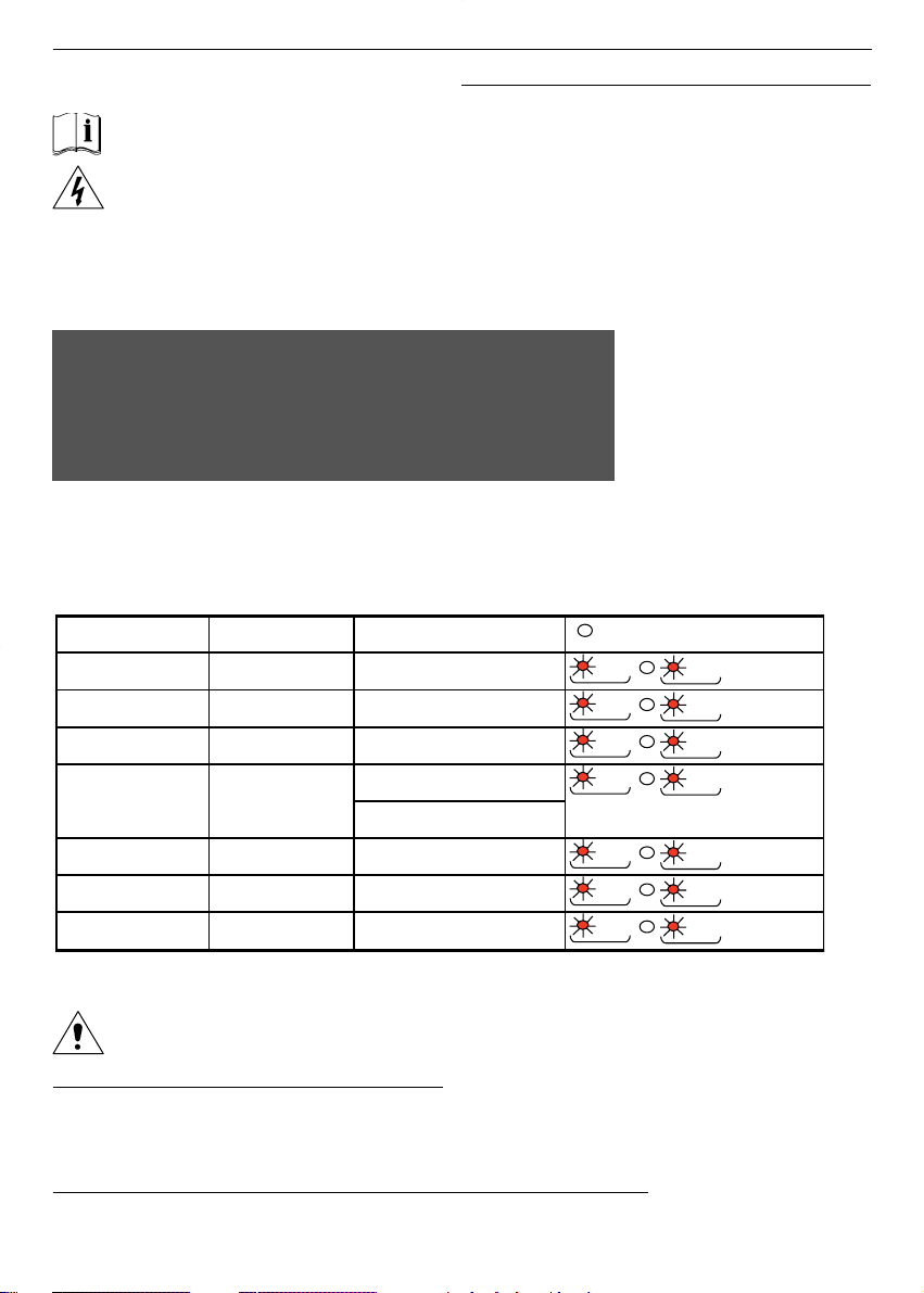
8. Troubleshooting
Information for users and maintenance personnel
Read this user’s manual and the operating instructions for the electric pump and diaphragm tank
(if installed).
Maintenance operations must be performed by qualified personnel only.
For further information refer to chapters 7 and 12.
8.1 Visual Signaling Devices
8.1.1 Operation Signals
These basic signals are integrated by the alarm signals. Therefore there could be combinations of signals such as green light on (power), yellow light off (pump off) and flashing red light (alarm).
8.1.2 Alarm signals
If an alarm is triggered the red light flashes more or less rapidly (flashing – pause – flashing) depending
on the cause of the system shutdown.
Be careful when servicing the system as it could restart automatically.
Shutdown caused by lack of water on suction side
If the system shuts down because there is not enough water on the suction side, it will restart automatically only if the external device re-enables its operation (float switch or pressure switch or switch ➞ chapters 6.2.7 and 6.2.8).
Shutdown caused by other problems except for lack of water on suction side
In all these cases the system restarts automatically after 20 seconds. If the cause of the malfunction persists, the system will shut down definitively after three attempts to start.
27
en
Red light (alarm)
Flashing
No signal from transmitter
shutdown
Or shutdown caused by open
external switch contact
Red light (alarm)
Off
No malfunction
Red light (alarm)
Flashing
Overcurrent shutdown
Flashing
Red light (alarm)
Converter overtemperature
shutdown
Red light (alarm)
Flashing
Motor overtemperature
shutdown
Red light (alarm)
Flashing
Shutdown caused by lack of
water on suction side
Red light (alarm)
Flashing
Red light (alarm)
Flashing
Low voltage (undervoltage)
shutdown
Problems at serial output (for 2pump units)
x 2
x 2
x 3
x 3
x 4
x 4
x 5
x 5
x 6
x 6
x 7
x 7
x 8
x 8
TKS_M0025_A_OT.XLS
TKS_M0026_A_OT.XLS

To reset the system, disconnect the power supply for at least one minute.
If 10 minutes elapse after an alarm without any other malfunctions occurring, the alarm counter is reset
and three new attempts are possible.
If two or more alarms are triggered simultaneously (e.g. due to motor overtemperature and lack of water),
only the first malfunction signal received by the control board is signaled.
WARNING ! The converter does not have a non-erasable alarm log, we therefore recommend that you
observe the flashing frequency carefully before disconnecting the power supply to the TKS
system.
For further information refer to chapters 8.1 and 12.
28
en

29
en
8.2 Troubleshooting Guide
PROBLEM PROBABLE CAUSE POSSIBLE REMEDY
The electric pump does not start No power supply Restore the power supply
Main switch on
Green light off Triggering of magneto-thermal Reset the switch
switch
The electric pump does not start or
it stops if it is already running *** = 2 flashes
The main switch is on Motor overload Check the working conditions
Green light on of the electric pump
Red light on (*** flashes) Damaged motor stator Check the motor
*** = 3 flashes
Converter overtemperature Check to see if anything is
preventing the proper cooling
of the converter
*** = 4 flashes
Motor overtemperature (if the Check the working conditions
terminal board is equipped with of the electric pump
the PTC protection)
*** = 5 flashes
Triggering of dry running Check the water level
Check the external device and
the related connection cables
*** = 6 flashes
Problems with the pressure Check the transmitter and
transmitter the related connection cable
*** = 7 flashes
The supply voltage is too low
Users closed Water leaks through the non-return Check the system in order to
Electric pump running with valve or in the system locate the leaks.Repair or replace
speed increasing and any faulty components.
decreasing cyclically Undersized surge tank Check the working conditions
Green light on of the electric pump
Yellow light on Ruptured surge tank diaphragm Replace the diaphragm
Red light off
Setting of work point not suitable Modify the system settings
for the system (the value is higher
than the pressure that the pump
is able to deliver)
Users open Setting of work point not suitable Modify the system settings
The electric pump does not start for the system (the value is equal
Green light on to zero)
Yellow light off
Red light off
The electric pump is running. Setting of work point not suitable Modify the system settings
There are vibrations in the pump for the system (the value is lower
or near the pump than the minimum pressure
that the pump can deliver)
Frequent starts and stops There may be problems with the Check the float switch and the
float switch in the suction tank tank
The electric pump is running There may be problems with the Check the hydraulic connection
always at maximum speed pressure transmitter between the transmitter and the
system
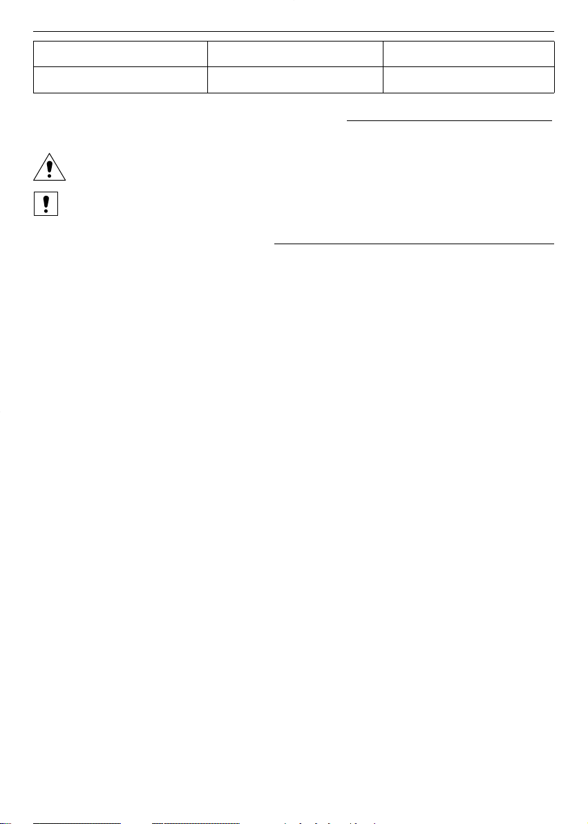
Triggering of general system Short circuit Check the connection cables
protection
Triggering of differential system Ground leakage Check the insulation of the
protection (circuit breaker) electric pump and cables
9. Spare Parts Information for maintenance personnel
Always state the exact model identification number and construction number when requesting technical
information or spare parts from our Sales and Service Center.
Use only original spare parts when replacing any faulty components.
The use of unsuitable spare parts can cause malfunctions, personal injury and damage to property.
10. Disposal Information for installers and maintenance personnel
After installing the unit, dispose of packaging according to legislation in force; if possible, re-utilize the
packaging for other purposes.
If the motor needs to be decommissioned and dismantled, observe the current legislation regarding sorted waste disposal.
11. Warranty
Refer to the sales documents for any information.
30
en

Français
« Traduction de la notice originale »
fr
1. Généralités
Avec le présent manuel, nous entendons fournir les informations indispensables pour l’installation, l’em-
ploi et l’entretien du convertisseur TEKNOSPEED associé à une électropompe LOWARA.
Lire ce manuel avant d’utiliser ce produit.
Une utilisation impropre peut causer des conditions de danger avec des dommages aux personnes et aux choses et entraîner la perte de la garantie.
Référez-vous aux manuels spécifiques pour les informations concernant les électropompes.
Les instructions et les prescriptions reportées ci-après concernent l’exécution standard.
Référez-vous à la documentation contractuelle de vente pour les variantes et les caractéristiques des
versions spéciales.
Précisez toujours le code d’identification du modèle, avec le numéro de construction, si vous devez demander des informations techniques ou des pièces de rechange à notre Service de Vente et AprèsVente.
Pour les instructions, situations et événements qui ne sont pas considérés dans le manuel ni dans la documentation de vente, contactez notre Service Après-Vente le plus proche.
2. Contrôle préliminaire
2.1. Contrôle visuel
Au moment de la livraison, contrôlez l’intégrité de l’emballage.
S’il est endommagé, retirez le produit de l’emballage et contrôlez visuellement qu’il n’a pas subi de dommages durant le transport.
Si le produit présente des dommages, informez notre revendeur dans les 8 jours qui suivent la livraison.
2.2. Manutention et stockage
Le produit est livré dans un emballage en carton ou en bois. Durant le transport et le stockage, protégez
le produit contre l’humidité, contre les sources de chaleur et contre les éventuels dommages mécani-
ques (chocs, chutes, …). Soulevez et déplacez le produit avec soin en utilisant des engins de levage appropriés.
Pour plus de détails, référez-vous au chapitre 4.
3. Utilisations
Le système TKS est composé d’une électropompe triphasée, du convertisseur TEKNOSPEED monophasé et d’un transmetteur électronique de pression (appelé également capteur de pression).
Le convertisseur monophasé TEKNOSPEED est indiqué pour le contrôle d’une électropompe triphasée
dans le respect des conditions prévues dans le présent manuel et de la tension/fréquence d’alimentation
spécifiée sur la plaquette des données.
Il assure la régulation de la pompe de manière à obtenir une pression constante au refoulement en fonction du signal provenant du transmetteur électronique de pression.
Le système TKS peut être utilisé pour les approvisionnements en eau dans les installations domestiques,
l’irrigation et la surpression.
Pour plus de détails, référez-vous au chapitre 12.
31

4. Limites d’emploi
Pour le stockage :
• Température ambiante : de -5°C à +40°C .
Pour l’utilisation :
Se référer aux manuels spécifiques pour les informations concernant les électropompes.
4.1 Système TKS (TEKNOSPEED installé sur l’électropompe)
Ne pas utiliser le produit dans des milieux ambiants en présence de poussières, acides, gaz corrosifs et/ou inflammables, etc. Ne pas utiliser l’électropompe pour pomper des liquides dangereux ou inflammables.
• Température ambiante : de +0°C à +40°C
• Humidité relative maximum : 50 % à + 40°C à condition qu’il n’y ait pas de phénomènes de
condensation
• Altitude maximum au-dessus du niveau de la mer : 1000 mètres
• Indice de protection : IP 55 (s’il est installé sur des moteurs avec indice IP 55 ou supérieur)
• Pression maximum de service : se référer au manuel d’instructions de l’électropompe
La version de série prévoit la fourniture d’un capteur avec maximum de l’échelle de 10 bars
(chapitre 4.2)
• Température du liquide pompé : de + 1°C à + 40 °C
• Nature du liquide pompé : eau privée de substances chimiquement agressives et de solides en
suspension
• Puissance nominale maximum de l’électropompe pouvant être associée au
convertisseur : 1,1 kW
• Tension d’alimentation du convertisseur : 1 x 230 V ± 10 % 50/60 Hz
• Tension de sortie du convertisseur (correspond à la tension d’alimentation du moteur) :
3 x 230 V ± 10 % 12-50 Hz (valeurs variables suivant la courbe tension/fréquence du
convertisseur)
• Courant nominal à l’entrée du convertisseur : 6,8 A
• Courant nominal à la sortie du convertisseur : 4,6 A
• Nombre maximum de démarrages horaires, équitablement répartis : lire le manuel
d’instructions de l’électropompe.
4.2 Capteur de pression
L’élément sensible de ce capteur est en silicium piézorésistif sensible à la pression, monté sur un petit
circuit imprimé flexible (TAB) et immergé dans une chambre à huile. La pression est transmise à l’élé-
ment à travers une membrane d’acier située dans la chambre à huile.
• Plage de pression : de 0 à 10 bars
• Alimentation : 21 Vcc par le TEKNOSPEED
• Signal de sortie : de 4 à 20 mA
• Connexion :
1
/4” mâle, en laiton nickelé
• Connecteur électrique : du type extractible, fourni avec deux mètres de câble blindé
• Indice de protection : IP 55
Pour des conditions ambiantes différentes, contacter notre Service de vente et après-vente.
5. Installation Informations pour l’installateur
Les opérations d’installation doivent être exécutées exclusivement par du personnel expérimenté
et qualifié. Utilisez les équipements et protections appropriées. Respectez les normes de prévention des accidents.
32
fr

Lisez ce manuel et celui de l’électropompe avant l’installation.
Si le produit présente des signes évidents d’endommagement, ne procédez pas à l’installation et contactez le Service Après-Vente.
Installez le produit dans un lieu à l’abri du gel et des intempéries, en respectant les limites d’emploi et de manière à garantir un refroidissement suffisant du moteur. Pour plus de détails, référezvous aux chapitres 4 et 12.
Respectez scrupuleusement les normes en vigueur en matière de sécurité et de prévention des
accidents.
6. Mise en service Informations pour l’installateur
Les opérations d’installation doivent être exécutées exclusivement par du personnel expérimenté
et qualifié. Utilisez les équipements et protections appropriées. Respectez les normes de prévention des accidents.
Lisez ce manuel et celui de l’électropompe avant l’installation.
6.1 Raccordement hydraulique de l’électropompe
Procédez aux raccordements hydrauliques suivant les normes et les lois en vigueur.
Le produit peut être utilisé avec raccordement direct de l’installation au service de distribution de l’eau
ou bien en prélevant l’eau dans un réservoir de première récolte.
En cas de raccordement au service d’eau, suivre les dispositions en vigueur émanant des organismes
responsables (Services Municipaux, agence de distribution, …). Il est conseillé d’installer un pressostat
côté aspiration pour la désactivation de l’électropompe en cas de basse pression dans le réseau (protection contre la marche à sec).
Vérifiez que la somme entre la pression du service d’eau et la pression maximum de la pompe ne
dépasse pas la valeur de la pression maximum de travail autorisée (pression nominale PN) de la
pompe proprement dite).
Si par exemple dans le système il y a une pompe CA 70/33, on a :
Hauteur d’élévation maximum de la pompe :
43 mètres (équivalant à une pression de fermeture de 4,3 bars environ)
Pression maximum de travail autorisée :
8 bars (PN 8)
Pression du service d’eau (considérez la valeur maximum) :
1,5 bar
Pression maximum de travail résultante :
4,3 + 1,5 = 5,8 inférieure à la limite de 8 bars
Si on utilise un réservoir de première récolte, il faut installer un flotteur pour la désactivation de
l’électropompe en cas de manque d’eau (protection contre la marche à sec).
Vous devez installer obligatoirement un manomètre côté refoulement car il pourrait être nécessai-
re de modifier la valeur d’étalonnage fait en usine en fonction des conditions d’installation réelles.
Normalement, le circuit est complété par l’installation de tuyaux flexibles sur l’aspiration et le refoulement,
vannes d’arrêt sur l’aspiration et le refoulement, clapet antiretour, surpresseur à membrane. Si vous voulez éviter de devoir vider l’installation pour le remplacement éventuel du surpresseur à membrane ou du
manomètre ou du capteur de pression, il est conseillé d’installer des vannes d’arrêt.
Dans le cas d’installation d’un clapet de retenue sur le côté refoulement de la pompe, placez le capteur
de pression en aval du clapet. Il est conseillé d’installer un robinet à utiliser dans la phase d’étalonnage
du système TKS (chapitre 6.3.3) s'il n’y a pas déjà un point de prélèvement à proximité de la pompe.
Pour plus de détails, référez-vous au chapitre 12.
33
fr

6.1.1 Réservoir sous pression (surpresseur à membrane)
Sur le côté refoulement de l’électropompe, il faut installer un surpresseur à membrane pour maintenir l’installation sous pression en l’absence de prélèvement d’eau pour éviter le fonctionnement continu de la
pompe.
Avec le convertisseur TEKNOSPEED, il n’est pas nécessaire de prévoir un surpresseur de grand volume
car il suffit que son volume nominal, en litres, soit égal à au moins 5% du débit maximum (litres/minute)
de la pompe avec un minimum de 8 litres de capacité nominale.
Exemple : débit maximum de la pompe = 60 litres/minute
volume nominal réservoir = 60 x 0,05 = 3 litres ➞ 8 litres
débit maximum de la pompe = 150 litres/minute
volume nominal réservoir = 150 x 0,05 = 7,5 litres ➞ 8 litres
Assurez-vous que le surpresseur est en mesure de supporter la pression maximum de
l’installation.
Contrôlez et réglez la pression de précharge correcte avant de raccorder le surpresseur à l’installation.
Si le surpresseur a déjà été raccordé, il faut vider l’installation avant de contrôler et de régler la pression
de précharge. Pour éviter cela, il est conseillé d’installer une vanne d’arrêt entre le raccord du surpresseur et la conduite de l’installation.
Pour calculer la valeur de la précharge du surpresseur, vous pouvez utiliser la formule suivante :
si elle est en bars ➞ pression de travail – 0,2 = pression de précharge
si elle est en kPa ➞ pression de travail – 20 = pression de précharge
6.2 Branchement électrique de l’électropompe
Procédez aux connexions électriques suivant les normes et les lois en vigueur.
Assurez-vous que le type de réseau électrique, la tension et la fréquence d’alimentation coïncident avec les données nominales du système TKS indiquées dans la plaquette des données.
Assurez une protection générale adéquate contre le court-circuit sur la ligne électrique
ATTENTION : même si le système TKS a une alimentation monophasée, le moteur de la pompe est
toujours triphasé connecté à 230 V. Les phases manquantes sont créées par le convertisseur. Pour plus
de détails, référez-vous au chapitre 12.
Avant d’effectuer des travaux, assurez-vous que toutes les connexions (y compris celles qui sont
sans potentiel) ne sont pas sous tension. Déconnectez toujours le convertisseur TEKNOSPEED
de l’alimentation électrique avant toute opération sur les parties électriques ou mécaniques de
l’installation.
Attendez au moins 1 minute après la déconnexion avant d’intervenir sur le TEKNOSPEED afin
que les condensateurs du circuit interne puissent se décharger.
6.2.1 Interrupteur magnétothermique différentiel
Si l’installation d’un interrupteur magnétothermique différentiel est prévue par les normes électriques locales en vigueur, s’assurer qu’il est d’un type approprié à l’installation. Les interrupteurs adaptés sont
ceux qui ont la courbe caractéristique pour courants de panne alternatifs et boutons unidirectionnels
(type A ou C).
On les reconnaît par la présence du symbole suivant :
6.2.2 Version avec câble et fiche
Le système TKS est fourni avec le câble d’alimentation muni d’une fiche électrique.
Installez la pompe de manière que la fiche et la prise de courant soient toujours bien accessibles
s’il se révélait nécessaire de désactiver le système.
Si le câble d’alimentation est endommagé, son remplacement doit être effectué par un centre de service
après-vente ou dans tous les cas par du personnel qualifié.
34
fr

6.2.3 Filtre d’entrée
Le convertisseur TEKNOSPEED a un filtre d’entrée et est conforme à la directive EMC.
6.2.4 Protection contre la surcharge du moteur
Le convertisseur TEKNOSPEED a une protection contre la surcharge incorporée qui garantit la protection
absolue quand il est associé à des moteurs ayant une puissance nominale égale à celle du convertisseur. Pour les moteurs de puissance inférieure, on utilise une protection supplémentaire (chapitre 6.2.5).
6.2.5 Protection contre la surchauffe du moteur (PTC)
Dans certains modèles de moteurs il peut y avoir une protection (thermistor) qui s’ajoute à celle contre la
surcharge qui est incorporée au convertisseur. Le thermistor (PTC) est fixé sur la base du bornier et connecté à la carte de commande à travers des petits câbles et des minifastons. Le dip-switch correspondant résultera sur la position PTC Y.
Pour plus de détails, référez-vous au chapitre 12.
6.2.6 Protection contre la surchauffe du convertisseur
Le convertisseur TEKNOSPEED a une protection contre la surchauffe incorporée.
6.2.7 Protection contre la marche à sec (flotteur)
Le convertisseur TEKNOSPEED peut être connecté à un dispositif extérieur pour la protection contre la
marche à sec de la pompe (chapitre 6.1). La méthode la plus traditionnelle prévoit l’emploi d’un flotteur
placé dans la cuve d’aspiration.
Pour connecter le câble du dispositif extérieur, il faut enlever le radiateur du convertisseur en utilisant une
clé Allen n°5 (couple maximum 6 Nm). Renversez le radiateur en faisant attention aux connexions avec le
bornier extractible. Il pourrait se révéler nécessaire également d’extraire le bornier. Remplacez un bouchon M 16 x 1,5 par l’un des serre-câbles fournis. Faites passer le câble du flotteur et connectez-le aux
bornes LOW 1 et LOW 2 (adaptées pour conducteurs de 0,5÷1 mm2). Vissez la plaquette et serrez le
serre-câble pour bloquer le câble. Vous pouvez utiliser un pressostat qui ouvre son contact quand la
pression descend en-dessous de la valeur d’étalonnage si vous raccordez l’aspiration de la pompe au
service d’eau.
Si vous n’utilisez aucun dispositif, laissez le shunt sur les deux bornes.
Utilisez le tournevis à fente (2,5 mm) fourni avec le système TKS pour les connexions sur le bornier du convertisseur.
Pour plus de détails, référez-vous au chapitre 12.
6.2.8 Activation extérieure
Vous pouvez connecter un interrupteur à la place du flotteur (chapitre 6.2.7). Avec ce dispositif extérieur,
vous pourrez activer ou désactiver le système. Il est conseillé d’utiliser un câble blindé. La dénudation du
câble doit être telle que le blindage résulte en contact avec la plaquette serre-câble.
Utilisez le tournevis à fente (2,5 mm) fourni avec le système TKS pour les connexions sur le bornier du convertisseur.
Pour plus de détails, référez-vous au chapitre 12.
6.2.9 Relais d’alarme
Le convertisseur TEKNOSPEED a un contact disponible pour obtenir une signalisation extérieure de blocage ou d’anomalie.
Ce contact est fermé si
• la pompe est arrêtée pour l’une des raisons suivantes: manque de tension
surcharge du moteur (chapitre 6.2.5)
surchauffe du moteur (chapitre 6.2.6)
surchauffe du convertisseur (chapitre 6.2.7)
capteur en panne ou non connecté (chapitre 6.2.11)
• manque d’eau à l’aspiration (chapitres 6.2.8 et 6.2.9)
Pour connecter le câble, il faut enlever le radiateur du convertisseur en utilisant une clé Allen n°5 (couple
maximum 6 Nm). Renversez le radiateur en faisant attention aux connexions avec le bornier extractible. Il
pourrait se révéler nécessaire également d’extraire le bornier. Remplacez un bouchon M 16 x 1,5 par l’un
des serre-câbles fournis. Faites passer le câble et connectez-le aux bornes COM et NC (adaptées pour
35
fr

conducteurs de 0,5÷1 mm2). Vissez la plaquette et serrez le serre-câble pour bloquer le câble.
Il est conseillé d’utiliser un câble blindé. La dénudation du câble doit être telle que le blindage résulte en
contact avec la plaquette serre-câble.
Utilisez le tournevis à fente (2,5 mm) fourni avec le système TKS pour les connexions sur le bornier du convertisseur.
Pour plus de détails, référez-vous au chapitre 12.
6.2.10 Interface série
Le convertisseur TEKNOSPEED a une interface série utilisable uniquement dans les systèmes de pompage avec deux pompes.
Ne connectez pas de fils aux bornes COM, TX, RX de l’interface série.
Pour plus de détails, référez-vous au chapitre 12.
6.2.11 Capteur de pression
Le système TKS est fourni avec le capteur de pression connecté au bornier du convertisseur
TEKNOSPEED.
Le capteur a un câble blindé de 2 mètres de long. Si vous devez regrouper le câble, ne l’enroulez pas
mais pliez-le en accordéon.
Pour plus de détails, référez-vous au chapitre 12.
6.2.12 Dip-switchs de réglage
Le convertisseur TEKNOSPEED a une série de microinterrupteurs (dip-switchs) qui en déterminent le
cycle de fonctionnement.
Ne modifiez pas les réglages faits en usine. Vous risqueriez d’endommager le système ou l’installation à laquelle il est raccordé.
Pour plus de détails, référez-vous au chapitre 12.
6.3 Première mise en service
6.3.1 Amorçage
Lisez le manuel d’instructions de l’électropompe
Remplissez d’eau la pompe et les tuyaux d’aspiration avant de mettre en service le système. Le
fonctionnement à sec peut endommager la pompe.
Faites démarrer le système avec la vanne d’arrêt sur le refoulement fermée puis ouvrez-la progressivement. Quand l’air présent dans le tuyau aura été expulsé, la pompe aura un fonctionnement régulier et silencieux
6.3.2 Vérification du sens de rotation du moteur
Il n’est pas nécessaire de contrôler le sens de rotation car il est déjà prédéterminé en usine.
6.3.3 Réglage de la pression de travail
Vous devez obligatoirement installer un manomètre côté refoulement car il pourrait être nécessai-
re de modifier la valeur du réglage effectué en usine suivant les conditions réelles d’installation et
les exigences du circuit.
Le système TKS est fourni avec le réglage déjà effectué en usine, prêt à l’utilisation.
Vous pouvez modifier la valeur de la pression suivant les besoins réels de l’installation de la façon suivante :
• Augmentation de la valeur de la pression
- Vérifiez que l’installation est sous pression, qu’il n’y a aucun point de prélèvement d’ouvert et que la
pompe est arrêtée. Si un point de prélèvement est ouvert, vous pouvez fermer la vanne d’arrêt située
36
fr

en aval de la pompe.
- Dévissez le bouchon qui protège la vis de réglage.
- Tournez lentement la vis de réglage vers la droite en utilisant un tournevis.
Utilisez le tournevis à fente (2,5 mm) fourni avec le système TKS. La vis de réglage a une course
limitée, inférieure à un tour, entre la valeur minimum (0 bar) et la valeur maximum (10 bars). Ne
forcez pas au-delà des limites car vous pourriez endommager la vis de réglage.
- La pompe démarre.
- Lisez la valeur de la pression sur le manomètre et continuez à tourner la vis de réglage jusqu’à ce que
l’aiguille du manomètre ait atteint la valeur désirée.
- Assurez-vous que la pression s’est stabilisée sur la valeur désirée.
- Si nécessaire, effectuez de légères variations en tournant à droite ou à gauche la vis de réglage.
Si vous devez réduire la pression de réglage, il est conseillé d’ouvrir lentement un point de prélèvement
(voir section suivante “Diminution de la valeur de la pression).
Assurez-vous que la nouvelle valeur choisie est comprise dans les limites de hauteur d’élévation
indiquées dans la plaque des données du système TKS.
- La pompe s’arrête au bout d’environ 60 secondes. La pression d’arrêt pourrait être légèrement
supérieure à la valeur désirée (chapitre 6.4.1)
• Diminution de la valeur de la pression
- Vérifiez que l’installation est sous pression, qu’il n’y a aucun point de prélèvement d’ouvert et que la
pompe est arrêtée.
- Dévissez le bouchon qui protège la vis de réglage.
- Laissez ouverte la vanne d’arrêt située en aval de la pompe.
- Ouvrez lentement un point de prélèvement ou le robinet d’essai (chapitre 6.1) en faisant descendre
lentement la pression.
- La pompe démarre.
- Tournez lentement la vis de réglage vers la gauche en utilisant un tournevis.
Utilisez le tournevis à fente (2,5 mm) fourni avec le système TKS. La vis de réglage a une course
limitée, inférieure à un tour, entre la valeur minimum (0 bar) et la valeur maximum (10 bars). Ne
forcez pas au-delà des limites car vous pourriez endommager la vis de réglage.
- Lisez la valeur de la pression sur le manomètre et continuez à tourner la vis de réglage jusqu’à ce que
l’aiguille du manomètre ait atteint la valeur désirée.
- Assurez-vous que la pression s’est stabilisée sur la valeur désirée.
- Si nécessaire, effectuez de légères variations en tournant à droite ou à gauche la vis de réglage
Assurez-vous que la nouvelle valeur choisie est comprise dans les limites de hauteur d’élévation
indiquées dans la plaque des données du système TKS.
- La pompe s’arrête au bout d’environ 60 secondes. La pression d’arrêt pourrait être légèrement
supérieure à la valeur désirée (chapitre 6.4.1).
Pour plus de détails, référez-vous au chapitre 12.
6.3.4 Indications lumineuses
Sur l’autocollant situé au-dessus du radiateur se trouve trois LED ayant les fonctions suivantes :
Lumière verte fixe Power Indique que le système TKS est sous tension
Lumière jaune fixe Run Indique que la pompe est en fonction
Lumière rouge clignotante Alarm Indique un état d’alarme
En cas d’alarme, la lumière rouge clignotera avec une fréquence variable suivant la cause du blocage du
système. Sauf pour le manque d’eau à l’aspiration, dans tous les autres cas le système redémarre automatiquement au bout de 20 secondes. Si la cause de l’anomalie persiste, au bout de trois tentatives de
redémarrage, le système se bloque définitivement, sauf en cas de manque d’eau à l’aspiration.
Pour plus de détails, référez-vous aux chapitres 8.1 et 12.
6.4 Description du produit Informations pour l’utilisateur
Le système TKS est composé d’une électropompe actionnée par l’intermédiaire d’un système de contrôle
automatique électronique (convertisseur de fréquence appelé également variateur de tours ou de vites-
37
fr

se) qui permet de fournir une pression constante en réduisant ou en augmentant le débit suivant les demandes.
6.4.1 Fonctionnement
Le système de contrôle automatique électronique prend le signal provenant d’un capteur de pression et
le compare à la valeur programmée.
Avec l’installation sous pression, la pompe est arrêtée. La baisse de pression provoquée par le prélèvement d’eau en un point quelconque du circuit entraîne la réduction du signal qui, à travers le système de
contrôle, fait démarrer la pompe en en réglant la vitesse de manière que la pression de référence (ou de
travail) soit rétablie. Si le prélèvement d’eau augmente, le système de contrôle fait augmenter la vitesse ;
si le prélèvement diminue, le système de contrôle fait diminuer la vitesse de la pompe. Quand le débit
maximum d’eau pouvant être fourni par la pompe est atteint, le système de contrôle fait travailler la
pompe à sa vitesse nominale maximum.
En cas d’augmentation de la pression, déterminée par une réduction du prélèvement d’eau, le signal
provenant du capteur augmente et, à travers le système de contrôle, le capteur fait réduire la vitesse de
la pompe.
Si l’interruption du prélèvement d’eau se fait brusquement (par exemple fermeture rapide des robinets),
le système de contrôle fait fonctionner la pompe à une vitesse minimum puis l’arrête au bout d’environ 60
secondes. Dans ce cas, la pression d’arrêt coïncide avec la valeur programmée.
Si l’interruption se fait lentement, le système fait fonctionner la pompe à une pression légèrement supé-
rieure (avec un maximum d’échelle du capteur égal à 10 bars ➞ + 0,2 bar) puis l’arrête au bout d’environ
60 secondes s’il n’y a pas eu de prélèvements d’eau.
En cas de présence de tension, la lumière verte (Power) est allumée.
Quand la pompe est en fonction, la lumière jaune (Run) est allumée.
En cas de blocage ou de fonctionnement anormal, la lumière rouge (Alarm) est allumée.
En cas d’alarme, la lumière rouge clignotera à une fréquence variable suivant la cause du blocage du système. Sauf pour le manque d’eau à l’aspiration, dans tous les autres cas le système redémarre automatiquement au bout de 20 secondes. Si la cause de l’anomalie persiste, au bout de trois tentatives de
redémarrage, le système se bloque définitivement.
Pour toute intervention de réglage et/ou de maintenance, adressez-vous à du personnel expert et
qualifié. N’essayez pas de modifier les réglages ou d’ouvrir le système de contrôle.
Lisez les manuels avant l’utilisation et conservez-les avec soin.
Conservez avec soin le tournevis fourni avec le système TKS.
7. Entretien Informations pour le réparateur
Respecter les règles ci-après s’il se révèle nécessaire d’intervenir sur le produit.
Les interventions d’entretien doivent être exécutées exclusivement par du personnel qualifié.
Avant toute intervention, assurez-vous que toutes les connexions (même celles qui sont sans po-
tentiel) ne sont pas sous tension.
Déconnectez toujours le convertisseur TEKNOSPEED de l’alimentation électrique avant toute
opération sur les parties électriques ou mécaniques de l’installation.
Attendez au moins 1 minute après la déconnexion avant d’intervenir sur le TEKNOSPEED afin
que les condensateurs du circuit interne puissent se décharger.
Lisez ce manuel d’instructions ainsi que ceux de l’électropompe et de l’éventuel surpresseur à
membrane.
7.1 Entretien ordinaire
Le système TKS n’a besoin d’aucun entretien ordinaire s’il est utilisé dans les limites prévues
au chapitre 4.
38
fr

Les pompes n’ont besoin d’aucun entretien ordinaire (lisez le manuel de la pompe).
Contrôlez la précharge d’air du surpresseur, s’il est présent, au moins une fois par an (chapitre 6.1.1).
7.2 Entretien extraordinaire
Utilisez les équipements et protections appropriées. Respectez les normes de prévention des
accidents.
Soulevez et déplacez le produit avec soin en utilisant des engins de levage appropriés.
N’utilisez que des pièces de rechange originales pour remplacer les éventuels composants usés
ou en panne.
ATTENTION !
Même si le système TKS a une alimentation monophasée, le moteur de la pompe est toujours triphasé
connecté à 230 V. Les phases manquantes sont créées par le convertisseur. Pour plus de détails, réfé-
rez-vous au chapitre 12.
8. Recherche des pannes Informations pour l’utilisateur et le réparateur
Lisez le présent manuel et ceux de l’électropompe et de l’éventuel surpresseur à membrane.
Les éventuelles interventions doivent être effectuées exclusivement par du personnel qualifié.
Pour plus de détails, référez-vous aux chapitres 7 et 12.
8.1 Signalisations lumineuses
8.1.1 Signalisations de fonctionnement
Ces signalisations essentielles sont intégrées par les signalisations d’alarme. Par conséquent, on peut
avoir des combinaisons de signalisation comme la lumière verte allumée (présence de tension), la lumiè-
re jaune éteinte (pompe arrêtée) et la lumière rouge clignotante (alarme).
39
fr
TKS_M0025_A_OT.XLS

8.1.2 Signalisations d’alarme
En cas d’alarme la lumière rouge clignotera à une fréquence variable (clignotements – pause – clignotements) suivant la cause du blocage du système.
Faites attention quand vous intervenez sur le système car il pourrait redé marrer
automatiquement.
Blocage pour manque d’eau à l’aspiration
En présence de blocage pour le manque d’eau à l’aspiration, le système redémarre automatiquement
seulement si le dispositif extérieur permet de nouveau le fonctionnement (flotteur ou pressostat ou interrupteur ➞ chapitres 6.2.7 et 6.2.8).
Blocage pour raisons autres que l’exclusion du manque d’eau à l’aspiration
Dans tous ces cas, le système redémarre automatiquement au bout de 20 secondes. Si la cause de l’a-
nomalie persiste, au bout de trois tentatives de démarrage, le système se bloque définitivement.
Pour réinitialiser le système, vous devez couper la tension d’alimentation pendant au moins une minute.
Si après une alarme, au moins 10 minutes s’écoulent sans aucune autre anomalie, le compteur d’alarmes
est mis à zéro et il peut y avoir de nouveau trois tentatives.
Dans le cas de deux causes d’alarmes simultanées ou plus (par exemple surchauffe moteur et manque
d’eau), seule la première qui parvient à faire arriver le signal à la carte de contrôle est signalée.
ATTENTION ! Le convertisseur n’a pas une mémoire indélébile des alarmes activées. Par conséquent,
il est conseillé d’observer attentivement la fréquence de clignotement avant de couper la
tension d’alimentation du système TKS
Pour plus de détails, référez-vous aux chapitres 8.1 et 12.
40
fr
TKS_M0026_A_OT.XLS

8.2 Guide
INCONVÉNIENT CAUSE PROBABLE REMÈDE POSSIBLE
L'électropompe ne démarre pas Manque d'alimentation Rétablissez l'alimentation
L'interrupteur général est enclenchéélectrique
Lumière verte éteinte Intervention de l'interrupteur Réarmez l'interrupteur
magnétothermique
L'électropompe ne démarre pas ou
s'arrÍte si elle est déjà en fonction *** = 2 clignotements
L'interrupteur général est enclenché Surcharge du moteur Vérifiez les conditions de
Lumière verte allumée travail de l'électropompe
Lumière rouge allumée Stator du moteur endommagé Contrôlez le moteur
(*** clignotements) *** = 3 clignotements
Surchauffe du convertisseur Contrôlez que rien
n'empêche le refroidissement
correct du convertisseur
*** = 4 clignotements
Surchauffe du moteur (si la Check the working conditions
protection PTC est présente of the electric pump
dans le bornier)
*** = 5 clignotements
Intervention de l'éventuelle Contrôlez le niveau de l'eau
protection contre la marche Contrôlez le dispositif extérieur
à sec et ses câbles de connexion
*** = 6 clignotements
Problèmes sur le capteur de Check the transmitter and
pression the related connection cable
*** = 7 clignotements
La tension d'alimentation est
trop basse
Prélèvements fermés Fuites d'eau à travers le clapet Contrôlez l'installation pour
Électropompe en fonction avec antiretour ou dans l'installation llocaliser les fuites. Réparez ou
augmentation et diminution cyclique remplacez les composants.
de la vitesse Éventuel surpresseur sous- Vérifiez les conditions de
Lumière verte allumée dimensionné travail de l'électropompe
Lumière jaune allumée Éventuel surpresseur avec la Remplacez la membrane
Lumière rouge éteinte membrane crevée
Réglage du point de travail Réglez de nouveau le système
non adapté à l'installation (valeur
plus élevée que la pression qui
peut être fournie par la pompe)
Prélèvements ouverts Réglage du point de travail Réglez de nouveau le système
L'électropompe ne démarre pas non adapté à l'installation (valeur
Lumière verte allumée égale à zéro)
Lumière jaune éteinte
Lumière rouge éteinte
L'électropompe est en fonction Réglage du point de travail Réglez de nouveau le système
Présence de vibrations dans la non adapté à l'installation (valeur
pompe ou à proximité de la plus élevée que la pression qui
pompe peut être fournie par la pompe)
L'électropompe est en fonction Problèmes possibles au flotteur Contrôlez le flotteur et la
Fréquents démarrages et arrêts situé dans la cuve d'aspiration cuve
L'électropompe est en fonction Problèmes possibles sur le Contrôlez le raccordement
toujours à la vitesse maximum capteur de pression hydraulique entre le capteur
et l'installation
41
fr

Intervention de la protection Short circuit Vérifiez les câbles de connexion
générale de l'installation
Intervention de la protection différen- Déperdition à la terre Vérifiez l'isolement de
tielle de l'installation (Disjoncteur) l'électropompe et des câbles.
9. Pièces de rechange Informations pour le réparateur
Précisez toujours le code d’identification exact du modèle, avec le numéro de construction, dans le cas
de demande d’informations techniques ou de pièces de rechange à notre Service de Vente ou AprèsVente.
N’utilisez que des pièces de rechange originales pour remplacer les éventuels composants en
panne.
L’utilisation de pièces de rechange non adaptées peut provoquer des anomalies de fonctionnement pour les personnes et les choses.
10. Mise au rebut Informations pour l’installateur et le réparateur
Après l’installation, mettez l’emballage au rebut suivant les lois en vigueur, si possible, réutilisez l’emballage pour d’autres utilisations.
S’il se révèle nécessaire de mettre le produit hors service et donc de le démonter, il faut respecter les lois
en vigueur pour la mise au rebut sélective des déchets.
11. Garantie
Pour tout renseignement, consultez la documentation contractuelle de vente.
42
fr

Deutsch
« Übersetzung der Originalbetriebsanleitung »
de
1. Allgemeines
Mit dem vorliegenden Handbuch sollen die erforderlichen Informationen für die Aufstellung, den Gebrauch
und die Wartung des Frequenzumformers TEKNOSPEED, gekoppelt mit einer LOWARA-Pumpe, geliefert
werden.
Die vorliegenden Anleitungen müssen vor dem Gebrauch des Produkts gelesen werden.
Eine unsachgemäße Verwendung bedingt die Gefahr von Personen- und Sachschäden und kann
zum Verfall der Garantieleistungen führen.
Für Informationen bezüglich der Pumpen nehmen Sie bitte auf die entsprechenden Handbücher
Bezug.
Die nachfolgend angeführten Anleitungen und Vorschriften beziehen sich auf die Standardausführung.
Sonderausführungen und deren Merkmale sind in den Verkaufsunterlagen beschrieben.
Bei Anforderung von technischen Informationen oder Ersatzteilen bei unserem Kunden- bzw.
Verkaufsdienst, sind immer die genaue Modellbezeichnung und die Baunummer anzugeben.
Für Anleitungen, Situationen und Ereignisse, die weder im vorliegenden Handbuch noch in den
Verkaufsunterlagen behandelt werden, wenden Sie sich bitte an die nächste Kundendienststelle.
2. Vorbereitende Inspektion
2.1 Sichtkontrolle
Bei Erhalt der Pumpe ist immer die Unversehrtheit der Verpackung zu kontrollieren.
Sollte diese beschädigt sein, so muss das Produkt ausgepackt und auf allfällige sichtbare
Transportschäden geprüft werden. Teilen Sie diese ggf. innerhalb von 8 Tagen ab Lieferdatum Ihrem
Wiederverkäufer mit.
2.2 Transport und Einlagerung
Das Produkt wird in einem Karton oder in einer Holzkiste verpackt geliefert. Während des Transports und
der Einlagerung muss es vor Feuchtigkeit, Wärmequellen und allfälligen mechanischen Schäden (Stöße,
Stürze, usw.) geschützt werden. Zum Anheben und Fortbewegen des Produkts sind geeignete
Hebegeräte zu verwenden; gehen Sie hierbei mit der erforderlichen Vorsicht vor.
Weitere Informationen finden Sie in Kapitel 4.
3. Anwendungen
Das TKS-System besteht aus einer Drehstrompumpe, dem Wechselstrom-Frequenzumformer TEKONOSPEED und einem elektronischen Druckübertragungsgerät (auch als Drucksensor bezeichnet).
Der Wechselstrom-Frequenzumformer TEKNOSPEED eignet sich für die Steuerung einer
Drehstrompumpe unter Berücksichtigung der im vorliegenden Handbuch angeführten Bedingungen und
der auf dem Datenschild angegebenen Speisespannung / -frequenz.
Durch den Frequenumformer wird die Pumpe so geregelt, dass ein konstanter Versorgungsdruck in
Funktion des vom elektronischen Drucksensors abgegebenen Signals erzielt wird.
Das TKS-System kann zur Wasserförderung im häuslichen Bereich, Beregnung und Druckerhöhung
verwendet werden.
Weitere Informationen siehe Kapitel 12.
43

4. Einschränkungen des Anwendungsbereichs
Einlagerung:
• Umgebungstemperatur: von -5°C bis +40°C
Gebrauch:
Hinweise und Informationen bezüglich der Motorpumpen finden Sie in den spezifischen
Bedienungsanleitungen.
4.1 TKS-System (auf der Pumpe installierter TEKNOSPEED)
Das Produkt darf nicht in staubreichen Umgebungen oder bei Vorhandensein von Säuren, korrosiven und explosionsgefährlichen Gasen verwendet werden.
Verwenden Sie die Pumpe auch nicht zum Fördern von gefährlichen und entflammbaren
Flüssigkeiten.
• Umgebungstemperatur: von +0°C bis +40°C
• Max. relative Luftfeuchtigkeit: 50 % bei + 40°C, nicht benetzend
• Max. Meereshöhe: 1000 m
• Schutzart: IP 55 (bei Installation auf Motoren mit Schutzart IP 55 oder höher)
• Max. Betriebsdruck: siehe spezifische Bedienungsanleitungen der Motorpumpe
Mit der Standardversion wird ein Frequenzgeber mit Vollausschlag von 10 bar geliefert (siehe
Kapitel 4.2)
• Temperatur des Fördermediums: von + 1°C bis + 40 °C
• Art des Fördermediums: Wasser ohne chemisch aggressive Substanzen und ohne schweben
de Feststoffteile
• Max. Nennleistung des mit der Pumpe koppelbaren Frequenzumformers: 1,1 kW
• Speisespannung des Frequenzumformers: 1 x 230 V ± 10 % 50/60 Hz
• Spannung am Ausgang des Frequenzumformers (diese entspricht der Speisespannung des
Motors):
3 x 230 V ± 10 % 12-50 Hz (variabler Wert in Funktion der Spannungs-/Frequenzlinie des
Frequenzumformers)
• Nennstrom am Eingang des Frequenzumformers: 6,8 A
• Nennstrom am Ausgang des Frequenzumformers: 4,6 A
• Max. stündliche Anlaufhäufigkeit bei gleichmäßiger Verteilung: siehe Bedienungsanleitungen
der Pumpe
4.2 Druckübertragungsgerät
Der Sensor dieses Übertragungsgeräts besteht aus einem piezo-widerstandsfähigen, druckempfindlichen Siliziumelement, das auf einer kleinen, biegsamen, gedruckten Schaltung (TAB) montiert und in
eine Ölkammer getaucht ist. Die Druckübertragung erfolgt über eine in der Ölkammer vorhandenen
Stahlmembrane.
• Druckbereich: von 0 bis 10 bar
• Speisung : 21 Vcc durch den TEKNOSPEED
• Ausgangssignal: von 4 bis 20 mA
• Anschluss:
1
/4” Steckanschluss in vernickeltem Messing
• Stromverbinder: herausziehbar, Lieferung mit 2 m langem abgeschirmtem Kabel
• Schutzart: IP 55
Bei anderen als den angeführten Umgebungsbedingungen wenden Sie sich bitte an unseren Kundenbzw. Verkaufsdienst.
44
de

5. Aufstellung
Informationen für den Installateur
Die Aufstellung darf ausschließlich von qualifiziertem Fachpersonal vorgenommen werden.
Verwenden Sie geeignete Ausrüstungen und Schutzvorrichtungen. Beachten Sie die
Unfallschutzvorschriften.
Vor der Aufstellung müssen das vorliegende Handbuch und jenes der Motorpumpe aufmerksam
gelesen werden.
Sollte das Produkt auffällige Schäden aufweisen, so darf es auf keinen Fall installiert werden. Wenden Sie
sich in diesem Fall an den Kundendienst.
Installieren Sie das Produkt an einem vor Frost und Witterung geschützten Ort und unter
Einhaltung der Anwendungseinschränkungen. Sorgen Sie für eine ausreichende Motorkühlung.
Weitere Informationen hierzu finden Sie in den Kapiteln 4 und 12.
Befolgen Sie genauestens die einschlägigen Sicherheits- und Unfallschutzvorschriften.
6. Inbetriebnahme Informationen für den Installateur
Die Inbetriebnahme darf ausschließlich von qualifiziertem Fachpersonal vorgenommen werden.
Verwenden Sie geeignete Ausrüstungen und Schutzvorrichtungen. Beachten Sie die
Unfallschutzvorschriften.
Vor der Aufstellung müssen das vorliegende Handbuch und jenes der Motorpumpe
aufmerksam gelesen werden.
6.1 Hydraulikanschluss der Pumpe
Die hydraulischen Anschlüsse müssen unter Beachtung der einschlägigen Normen und Gesetze
vorgenommen werden.
Das Produkt kann bei direkter Verbindung der Anlage mit der Wasserleitung oder mit Wasserförderung
aus einem Sammelbecken verwendet werden.
Beim Anschluss an die Wasserleitung beachten Sie die von der zuständigen Behörde (Gemeinde,
Wasserwerk, usw.) erlassenen Bestimmungen. Auf der Saugseite sollte auf jeden Fall ein Druckwächter
zum Ausschalten der Motorpumpe bei niedrigem Druck in der Wasserleitung installiert werden
(Trockenlaufschutz).
Stellen Sie sicher, dass die Summe des Druckes der Wasserleitung und des Höchstdruckes der
Pumpe den Wert des max. zulässigen Arbeitsdruckes der Pumpe nicht übersteigt (Nenndruck PN).
Wird beispielsweise eine Pumpe Baureihe CA 70/33 für das System verwendet, so errechnen sich folgende Werte:
Max. Förderhöhe der Pumpe:
43 Meter (entsprechend einem Schließdruck von ca. 4,3 bar)
Max. zulässiger Arbeitsdruck:
8 bar (PN 8)
Druck der Wasserleitung (hierbei ist der Höchstwert heranzuziehen):
1,5 bar
Daraus errechneter max. Arbeitsdruck:
4,3 + 1,5 = 5,8 liegt unter der Grenze von 8 bar
Wird das Wasser aus einem Sammelbecken gefördert, so muss ein Schwimmerschalter zum Ausschalten
der Pumpe bei Fehlen von Wasser installiert werden (Trockenlaufschutz).
45
de

Zwingend vorgeschrieben ist die Installation eines Druckmessers auf der Druckseite, weil eine
Änderung der werkseitigen Einstellungen in Funktion der effektiven Installationsbedingungen
erforderlich werden könnte.
Normalerweise wird die Anlage durch die Installation von biegsamen Saug- und Druckleitungen,
Sperrventilen auf der Saug- und Druckleitung, einem Rückschlagventil und einem
Membrandruckbehälter vervollständigt. Soll eine vollständige Entleerung der Anlage beim Austausch des
Membrandruckbehälters oder des Druckmessers bzw. des Drucksensors verhindert werden, so empfiehlt sich die Installation von Sperrventilen.
Bei Installation eines Rückschlagventils auf der Druckleitung der Pumpe, muss der Drucksensor hinter
dem Ventil montiert werden. Man empfiehlt die Installation eines Hahnes, der bei der Einstellung des
TKS-Systems (Kapitel 6.3.3) verwendet werden kann, wenn keine andere Entnahmestelle in Pumpennähe
vorhanden sein sollte.
Für weitere Informationen nehmen Sie bitte auf Kapitel 12 Bezug.
6.1.1 Druckbehälter (Membran-Druckkessel)
Auf der Druckseite der Motorpumpe muss ein Membrandruckbehälter installiert werden, um die Anlage
bei fehlender Wasserabnahme unter Druck zu halten. Dadurch wird der Dauerbetrieb der Pumpe verhindert.
Mit dem Frequenzumformer TEKNOSPEED können auch Druckkessel mit geringem Volumen verwendet
werden; es genügt in der Tat, dass das Nenn-Fassungsvermögen des Kessels in Litern mindestens 5 %
der max. Fördermenge der Pumpe (l/min), mit einer Mindest-Nennleistung von 8 l, entspricht.
Beispiel : Max. Fördermenge der Pumpe = 60 Liter pro Minute
Nennvolumen des Behälters = 60 x 0,05 = 3 Liter ➞ 8 Liter
Max. Fördermenge der Pumpe = 150 Liter pro Minute
Nennvolumen des Behälters = 150 x 0,05 = 7,5 Liter ➞ 8 Liter
Versichern Sie sich, dass der Druckbehälter dem max. Anlagendruck standhält.
Kontrollieren und regulieren Sie ggf. den korrekten Vorbelastungsdruck vor dem Anschluss des
Druckbehälters an die Anlage.
Sollte der Druckbehälter schon angeschlossen sein, so muss die Anlage vor der Kontrolle und
Einstellung des Vorbelastungsdruckes entleert werden. Um dies zu umgehen, empfiehlt sich die
Installation eines Sperrventils zwischen dem Anschluss des Druckbehälters und der Anlagenleitung.
Zur Bestimmung des korrekten Vorbelastungsdruckes des Druckkessels kann folgende Formel verwendet werden:
Berechnung in bar ➞ Arbeitsdruck – 0,2 = Vorbelastungsdruck
Berechnung in kPa ➞ Arbeitsdruck – 20 = Vorbelastungsdruck
6.2 Stromanschluss
Die elektrischen Anschlüsse müssen unter Einhaltung der einschlägigen Vorschriften vorgenom-
men werden.
Kontrollieren Sie, ob die Art des Speisenetzes, Spannung und Speisefrequenz mit den auf dem
Datenschild angeführten Nennwerten übereinstimmen. Sehen Sie einen geeigneten allgemeinen
Kurzschlussschutz auf der Stromleitung vor.
ACHTUNG: Obwohl das TKS-System mit Wechselstrom versorgt wird, ist der Pumpenmotor an 230 V
Drehstrom angeschlossen. Die fehlenden Phasen werden vom Frequenzumformer generiert. Weitere
Informationen hierzu finden Sie in Kapitel 12.
Versichern Sie sich vor allen Eingriffen, dass alle Anschlüsse (auch jene ohne Potential) span-
nungsfrei sind. Vor jeglichem Eingriff an den elektrischen oder mechanischen Teilen der Anlage
ist der Frequenzumformer TEKNOSPEED vom Stromnetz zu trennen.
Nach dem Abtrennen des Netzes ist mindestens 1 Minute abzuwarten, bevor mit den Eingriffen
am TEKNOSPEED begonnen wird, um das Entladen der Kondensatoren des internen Kreises zu
gewährleisten.
46
de

6.2.1 Differential-Magnetschalter
Wenn die örtlichen elektrischen Vorschriften die Installation eines Differential-Magnetschalters vorschreiben, muss man sich vergewissern, dass dieser der Art der Analge entspricht. Geeignete Schalter sind
jene mit einer Kennlinie für Wechselfehlerstrom und eingerichteten Drucktasten (Typ A oder C).
Man erkennt sie an der Kennzeichnung mit folgenden Symbol:
6.2.2 Version mit Kabel und Stecker
Das TKS-System wird mit Speisekabel und Stecker geliefert.
Installieren Sie die Pumpe so, dass der Stecker und die entsprechende Steckdose immer gut
zugänglich bleiben, wenn ein Ausschalten des Systems erforderlich werden sollte.
Bei Beschädigung des Speisekabels muss der Austausch durch eine Kundendienststelle oder auf jeden
Fall von Fachpersonal vorgenommen werden.
6.2.3 Eingangsfilter
Der Frequenzumformer TEKNOSPEED verfügt über einen Eingangsfilter und entspricht der EMCRichtlinie.
6.2.4 Überlastschutz des Motors
Der Frequenzumformer TEKNOSPEED verfügt über einen eingebauten Überlastschutz, der einen vollkommenen Schutz gewährleistet, wenn er mit Motoren mit gleicher Nennleistung wie jene des
Frequenzumformers gekoppelt wird. Bei Koppelung mit Motoren mit einer geringeren Leistung ist ein zusätzlicher Schutz zu verwenden (Kapitel 6.2.5).
6.2.5 Überhitzungsschutz des Motors (PTC)
Auf einigen Motormodellen kann ein (Thermistor-)Schutz zusätzlich zu dem im Frequenzumformer eingebauten Überlastschutz vorhanden sein. Der Thermistor (PTC) ist auf der Basis des Klemmenbretts angebracht und mittels Kabel und Minifaston mit der Steuerkarte verbunden. Der entsprechende Dip-Switch
steht auf PTC Y.
Weitere Informationen finden Sie in Kapitel 12.
6.2.6 Überhitzungsschutz des Frequenzumformers
Der Frequenzumformer TEKNOSPEED ist mit einem eingebauten Überhitzungsschutz ausgestattet.
6.2.7 Trockenlaufschutz (Schwimmerschalter)
Der Frequenzumformer TEKNOSPEED kann mit einem externen Trockenlaufschutz der Pumpe verbunden werden (Kapitel 6.1). Üblicherweise wird in diesem Fall ein Schwimmerschalter in der Saugwanne
verwendet.
Um das Kabel der externen Vorrichtung anzuschließen, muss der Kühler des Frequenzumformers mit
Hilfe eines Maul-Schraubenschlüssels Nr. 5 (max. Drehmoment 6 Nm) abgenommen werden. Stellen Sie
den Kühler auf den Kopf und achten Sie dabei auf die Anschlüsse mit dem herausnehmbaren
Klemmenbrett. Ggf. muss das Klemmenbrett abgenommen werden. Ersetzen Sie den Stopfen M 16 x 1.5
mit einem der mitgelieferten Kabelniederhalter. Führen Sie das Kabel des Schwimmerschalters durch
und schließen Sie es an die durch LOW 1 und LOW 2 gekennzeichneten Klemmen an (geeignet für
Verbinder von 0,5÷1 mm2). Schrauben Sie das Kabelfeststellplättchen an und ziehen den
Kabelniederhalter zu, um das Kabel zu blockieren. Beim Anschluss der Saugleitung der Pumpe an die
Wasserleitung, können Sie einen Druckwächter verwenden, der seinen Kontakt öffnet, wenn der Druck
unter den voreingestellten Wert absinkt. Falls Sie keine externe Vorrichtung verwenden, lassen Sie beide
Klemmen gebrückt.
Verwenden Sie den mit dem TKS-System gelieferten Schraubenzieher mit flacher Klinge (2,5 mm)
für den Anschluss des Klemmenbretts an den Frequenzumformer.
Weitere Informationen finden Sie in Kapitel 12.
47
de

6.2.8 Externe Befähigung
Anstelle des Schwimmerschalters kann ein Schalter angeschlossen werden (Kapitel 6.2.7). Mit dieser externen Vorrichtung kann das System ein- bzw. ausgeschaltet werden. Es empfiehlt sich die Verwendung
eines abgeschirmten Kabels. Die Abisolierung des Kabels muss so ausgeführt sein, dass die entsprechende Abschirmung das Kabelfeststellplättchen berührt.
Verwenden Sie den mit dem TKS-System gelieferten Schraubenzieher mit flacher Klinge (2,5 mm)
für den Anschluss des Klemmenbretts an den Frequenzumformer.
Weitere Informationen finden Sie in Kapitel 12.
6.2.9 Alarmrelais
Der Frequenzumformer TEKNOSPEED verfügt über einen Kontakt für eine externe Anzeige eines
Stillstandes oder einer Betriebsstörung.
Dieser Kontakt ist offen, wenn
• die Pumpe aus einem der folgenden Gründe anhält: Spannungsausfall
Überlastung des Motors (Kapitel 6.2.5)
Überhitzung des Motors (Kapitel 6.2.6)
Überhitzung des Frequenzumformers (Kapitel 6.2.7)
Sensor defekt oder nicht angeschlossen
(Kapitel 6.2.11)
• Wasser zum Ansaugen fehlt (Kapitel 6.2.8 und 6.2.9)
Um das Kabel anzuschließen, muss der Kühler des Frequenzumformers mit Hilfe eines MaulSchraubenschlüssels Nr. 5 (max. Drehmoment 6 Nm) abgenommen werden. Stellen Sie den Kühler auf
den Kopf und achten Sie dabei auf die Anschlüsse mit dem herausnehmbaren Klemmenbrett. Ggf. muss
das Klemmenbrett abgenommen werden. Ersetzen Sie den Stopfen M 16 x 1.5 mit einem der mitgelieferten Kabelniederhalter. Führen Sie das Kabel durch und schließen Sie es an die durch COM und NC
gekennzeichneten Klemmen an (geeignet für Verbinder von 0,5÷1 mm2). Schrauben Sie das
Kabelfeststellplättchen an und ziehen den Kabelniederhalter zu, um das Kabel zu blockieren.
Es empfiehlt sich die Verwendung eines abgeschirmten Kabels. Die Abisolierung des Kabels muss so
ausgeführt sein, dass die entsprechende Abschirmung das Kabelfeststellplättchen berührt.
Verwenden Sie den mit dem TKS-System gelieferten Schraubenzieher mit flacher Klinge (2,5 mm)
für den Anschluss des Klemmenbretts an den Frequenzumformer.
Weitere Informationen finden Sie in Kapitel 12.
6.2.10 Serienschnittstelle
Der Frequenzumformer TEKNOSPEED verfügt über eine Serienschnittstelle, die nur für die
Pumpensysteme mit zwei Pumpen verwendet werden kann.
Verbinden Sie keine Drähte mit den Klemmen COM, TX, RX der Serienschnittstelle.
Weitere Informationen finden Sie in Kapitel 12.
6.2.11 Druckübertragungsgerät
Das TKS-System wird mit einem Druckübertragungsgerät geliefert, das mit dem Klemmenbrett des
Frequenzumformers TEKNOSPEED verbunden ist.
Das Übertragungsgerät hat ein 2 m langes abgeschirmtes Kabel. Soll dieses aufgewickelt werden, so
rollen Sie es nicht auf, sondern falten es wie eine Ziehorgel zusammen.
Weitere Informationen finden Sie in Kapitel 12.
6.2.12 Dip-Switch zur Regulierung
Der Frequenzumformer TEKNOSPEED verfügt über eine Reihe von Mikroschaltern (Dip-Switches), die
den Betriebsablauf bestimmen.
Verändern Sie auf keinen Fall die werkseitigen Einstellungen. Dadurch könnte das System bzw.
die Anlage, in welche das System eingebaut ist, Schaden erleiden.
Weitere Informationen finden Sie in Kapitel 12.
6.3 Erste Inbetriebnahme
48
de

6.3.1 Anfüllen
Lesen Sie die Betriebsanleitungen der Motorpumpe.
Füllen Sie die Pumpe und die Saugleitungen vor dem Anlassen des Systems mit Wasser an.
Durch einen allfälligen Trockenlauf kann die Pumpe beschädigt werden.
Lassen Sie das System dann mit geschlossenem Sperrventil der Druckleitung an und öffnen dies dann
langsam. Nach Entweichen der in der Leitung vorhandenen Luft, beginnt die Pumpe ruhig und regelmäßig zu laufen.
6.3.2 Kontrolle der Drehrichtung des Motors
Eine Kontrolle der Drehrichtung ist nicht notwendig, weil diese werkseitig vorbestimmt ist.
6.3.3 Eichung des Arbeitsdruckes
Die Installation eines druckseitigen Druckmessers ist zwingend vorgeschrieben, weil es unter
Umständen erforderlich sein könnte, die werkseitigen Einstellungen an die effektiven
Installationsbedingungen und Anforderungen an die Anlage anzupassen.
Das TKS-System wird mit einer werkseitigen Einstellung geliefert, die den Betrieb bereits ermöglicht.
Um den Druckwert an die tatsächlichen Betriebsbedingungen anzupassen, geht man wie folgt vor:
• Erhöhen des Druckwerte
s
- Stellen Sie sicher, dass die Anlage unter Druck steht, kein Abnehmer offen ist und die Pumpe stillsteht.
Sollte irgendein Abnehmer offen sein, so muss das der Pumpe nachgeschaltete Sperrventil geschlossen werden.
- Schrauben Sie den Stopfen zum Schutz der Stellschraube ab.
- Drehen Sie die Stellschraube mit Hilfe eines Schraubenziehers langsam nach rechts.
Verwenden Sie hierzu den mit dem TKS-System gelieferten Schraubenzieher mit flacher Klinge
(2,5 mm). Der Hub der Stellschraube ist auf weniger als eine Runde beschränkt und ermöglicht
Druckwerte von 0 bar (Mindestwert) bis 10 bar (Höchstwert). Verzichten Sie auf Kraftanwendung,
weil die Schraube dadurch beschädigt werden könnte.
- Die Pumpe läuft nun an.
- Lesen Sie den Druckwert am Druckmesser ab und drehen Sie die Stellschraube langsam weiter,
bis der Zeiger des Druckmessers den gewünschten Wwert erreicht.
- Versichern Sie sich, dass dieser Wert stabil bleibt.
- Falls erforderlich, sind kleine Anpassungen durch kurzes Links- oder Rechtsdrehen der Stellschraube
möglich. Soll der Druckwert vermindert werden, so öffnen Sie ein wenig einen Abnehmer (siehe
nächstes Kapitel "Vermindern des Druckwertes").
Stellen Sie sicher, dass der neue Wert innerhalb des auf dem Datenschild des TKS-Systems an-
geführten Förderhöhenbereichs liegt.
- Nach etwa 60 Sekunden hält die Pumpe an. Der Druckwert nach dem Anhalten könnte leicht über
dem gewünschten Wert liegen (Kapitel 6.4.1).
• Vermindern des Druckwertes
- Stellen Sie sicher, dass die Anlage unter Druck steht, kein Abnehmer offen ist und die Pumpe stillsteht.
- Schrauben Sie den Stopfen zum Schutz der Stellschraube ab.
- Lassen Sie das der Pumpe nachgeschaltete Sperrventil offen.
- Öffnen Sie nun ein wenig einen Abnehmer oder den Testhahn (Kapitel 6.1); dadurch sinkt der Druck
allmählich ab.
- Die Pumpe läuft an.
- Drehen Sie die Stellschraube mit Hilfe eines Schraubenziehers langsam nach links.
Verwenden Sie hierzu den mit dem TKS-System gelieferten Schraubenzieher mit flacher Klinge
(2,5 mm). Der Hub der Stellschraube ist auf weniger als eine Runde beschränkt und ermöglicht
Druckwerte von 0 bar (Mindestwert) bis 10 bar (Höchstwert). Verzichten Sie auf Kraftanwendung,
weil die Schraube dadurch beschädigt werden könnte.
49
de

- Lesen Sie den Druckwert am Druckmesser ab und drehen Sie die Stellschraube langsam weiter,
bis der Zeiger des Druckmessers den gewünschten Wert erreicht.
- Versichern Sie sich, dass dieser Wert stabil bleibt.
- Falls erforderlich, sind kleine Anpassungen durch kurzes Links- oder Rechtsdrehen der
Stellschraube möglich.
Stellen Sie sicher, dass der neue Wert innerhalb des auf dem Datenschild des TKS-Systems an-
geführten Förderhöhenbereichs liegt.
- Nach etwa 60 Sekunden hält die Pumpe an. Der Druckwert nach dem Anhalten könnte leicht über
dem gewünschten Wert liegen (Kapitel 6.4.1).
Weitere Informationen finden Sie in Kapitel 12.
6.3.4 Leuchtanzeigen
Auf dem Klebeetikett oberhalb des Kühlers sind drei Leuchtanzeigen mit folgenden Funktionen vorhanden:
Anhaltendes grünes Licht Power Zeigt das Vorhandensein von Spannung im TKS-System an
Anhaltendes gelbes Licht Run Zeigt den Pumpenbetrieb an.
Blinkendes rotes Licht Alarm Zeigt einen Alarmzustand an.
Bei einem Alarm blinkt das rote Licht mit variabler Frequenz je nach Ursache des Systemsunterbruchs.
Das System läuft nach 20 Sekunden automatisch wieder an, außer wenn kein Wasser in der Saugleitung
vorhanden ist. Bleibt die Ursache der Betriebsstörung bestehen, so hält das System nach drei
Anlaufversuchen definitiv an (ausgenommen Fehlen von Wasser beim Ansaugen – siehe oben).
Weitere Informationen finden Sie in Kapitel 8.1 und 12.
6.4 Beschreibung des Produkts Informationen für den Bediener
Das TKS-System besteht aus einer Motorpumpe, die über ein automatisches elektronisches
Kontrollsystem (Frequenzumformer, bekannt auch als Drehzahlregler) gesteuert wird. Dadurch wird ein
konstanter Druck durch Vermindern bzw. Erhöhen der Fördermenge aufgrund des effektiven Bedarfs versichert.
6.4.1 Betrieb
Das automatische elektronische Kontrollsystem empfängt das vom Drucksensor übermittelte Signal und
vergleicht es mit dem vorgegebenen Wert.
Ist die Anlage unter Druck, so steht die Pumpe still. Das Absinken des Druckes, verursacht durch die
Wasserentnahme von Seiten eines Abnehmers, verursacht die Reduzierung des Signals und veranlässt
das Kontrollsystem zum Einschalten der Pumpe mit einer Geschwindigkeit, durch die der Bezugsdruck
(oder Arbeitsdruck) wieder hergestellt wird. Einem höheren Wasserbedarf entspricht automatisch die
Erhöhung der Geschwindigkeit der Pumpe; demgegenüber vermindert sich die Pumpengeschwindigkeit,
wenn die Abnahmeleistung geringer wird. Bei Erreichen der höchsten von der Pumpe lieferbaren
Wassermenge, arbeitet die Pumpe bei höchster Nenngeschwindigkeit.
Erhöht sich der Druck aufgrund einer geringeren Wasserentnahme, so wird das vom Sensor ausgehende
Signal stärker und veranlasst das Kontrollsystem zu einer Verminderung der Pumpengeschwindigkeit.
Wird die Wasserentnahme plötzlich unterbrochen (zum Beispiel durch ein schnelles Zudrehen der
Wasserhähne), so reduziert das Kontrollsystem die Pumpengeschwindigkeit auf ein Minimum; die Pumpe
hält dann nach ca. 60 Sekunden ganz an. In diesem Fall entspricht der Druck beim Anhalten dem vorgegebenen Wert.
Erfolgt die Unterbrechung langsam, so läuft die Pumpe mit einem geringfügig höheren Druck (mit
Vollausschlag des Übertragungsgeräts gleich 10 bar ➞ + 0,2 bar); auch in diesem Fall hält sie nach
etwa 60 Sekunden endgültig an, wenn kein Wasser mehr entnommen wird.
Bei Vorhandensein von Spannung leuchtet das grüne Licht (Power).
Bei Pumpenbetrieb leuchtet das gelbe Licht (Run).
Bei einem Betriebsausfall oder einer Störung blinkt das rote Licht (Alarm).
Bei einem Alarm blinkt das rote Licht mit variabler Frequenz je nach Ursache des Systemsunterbruchs.
50
de

Das System läuft nach 20 Sekunden automatisch wieder an, außer wenn kein Wasser in der Saugleitung
vorhanden ist. Bleibt die Ursache der Betriebsstörung aufrecht, so hält das System nach drei
Anlaufversuchen definitiv an.
Wenden Sie sich zwecks Einstellung und/oder Wartung aussschließlich an qualifiziertes
Fachpersonal. Versuchen Sie auf keinen Fall, die Einstellungen selbst zu ändern oder das
Kontrollsystem zu öffnen.
Vor dem Gebrauch sind die Bedienungsanleitungen aufmerksam zu lesen und in der Folge
sorgfältig aufzubewahren.
Ebenso muss der mit dem TKS-System gelieferte Schraubenzieher sorgfältig verwahrt werden.
7. Wartung Informationen für das Wartungspersonal
Bei den ggf. erforderlichen Eingriffen sind die nachfolgenden Vorschriften zu beachten.
Wartungseingriffe dürfen grundsätzlich nur von Fachpersonal vorgenommen werden.
Vor jeglichem Wartungseingriff ist sicherzustellen, dass alle elektrischen Anschlüsse (auch jene
ohne Potential) spannungsfrei sind.
Vor jeglichem Eingriff an den elektrischen oder mechanischen Teilen der Anlage ist der
Frequenzumformer TEKNOSPEED vom Stromnetz zu trennen.
Nach dem Abtrennen des Netzes ist mindestens 1 Minute abzuwarten, bevor mit den Eingriffen
am TEKNOSPEED begonnen wird, um das Entladen der Kondensatoren des internen Kreises zu
gewährleisten.
Lesen Sie vor allfälligen Eingriffen die Betriebsanleitungen der Motorpumpe und des eventuell
vorhandenen Membrandruckbehälters.
7.1 Ordentliche Wartung
Das TKS-System bedarf keiner ordentlichen Wartung, sofern es gemäß den in Kapitel 4 angeführten
Bedingungen verwendet wird.
Die Pumpen sind wartungsfrei (siehe Pumpen-Handbuch).
Mindestens einmal jährlich muss die Luftvorbelastung des eventuell vorhandenen Druckbehälters kontrolliert werden (Kapitel 6.1.1).
7.2 Außerordentliche Wartung
Verwenden Sie geeignete Werkzeuge und Schutzvorrichtungen. Beachten Sie die
Unfallverhütungsvorschriften. Zum Anheben und Transportieren der Pumpen sind geeignete
Hebemittel zu verwenden und mit Sorgfalt vorzugehen.
Verwenden Sie beim Austausch von verschlissenen oder defekten Teilen ausschließlich
Originalersatzteile.
ACHTUNG!
Obwohl das TKS-System mit Wechselstrom gespeist wird, handelt es sich beim Pumpenmotor um einen
an 230 V angeschlossenen Drehstrommotor. Die fehlenden Phasen werden vom Frequenzumformer generiert. Weitere Informationen finden Sie in Kapitel 12.
51
de

8. Schadenssuche
Informationen für den Bediener und das Wartungspersonal
Lesen Sie aufmerksam die vorliegenden Bedienungsanleitungen, sowie jene der Pumpe und
eines allfälligen Membrandruckbehälters.
Eventuell erforderliche Eingriffe dürfen nur von Fachpersonal vorgenommen werden.
Weitere Informationen finden Sie in den Kapitel 7 und 12.
8.1 Leuchtsignale
8.1.1 Betriebssignale
Diese wesentlichen Signale werden durch die Alarmsignale ergänzt. Es kann daher vorkommen, dass
Signalkombinationen anfallen, z. B. ein anhaltend eingeschaltetes grünes Licht (Spannung vorhanden)
mit ausgeschaltetem gelben Licht (Pumpe steht still) und blinkendem roten Licht (Alarm).
8.1.2 Alarmsignale
Bei einem Alarm blinkt das rote Licht mit unterschiedlicher Frequenz (Blinken - Pause - Blinken) je nach
der Ursache, die den Systemstillstand ausgelöst hat.
Achtung! Das System könnte während den Eingriffen automatisch anlaufen.
Ausfall wegen Fehlen von Wasser beim Ansaugen
Bei einem durch Fehlen von Wasser in der Saugleitung verursachten Stillstand, läuft das System nur
dann automatisch an, wenn der Betrieb durch die externe Vorrichtung befähigt wird (Schwimmerschalter
oder Druckwächter bzw. Schalter ➞ Kapitel 6.2.7 und 6.2.8).
52
de
TKS_M0025_A_OT.XLS
TKS_M0026_A_OT.XLS

Ausfall wegen anderer Ursachen (ausgenommen Fehlen von Wasser beim Ansaugen)
In allen anderen Fällen läuft das System nach 20 Sekunden automatisch wieder an. Bleibt die Ursache
des Ausfalls bestehen, so hält das System nach drei Anlaufversuchen definitiv an.
Um diese Situation rückzustellen, muss das System etwa eine Minute lang von der Spannung getrennt
werden.
Verstreichen nach einem Alarm mindestens 10 Minuten ohne weitere Betriebsstörung, so wird der
Alarmzähler rückgestellt, und es werden drei neue Anlaufversuche möglich.
Beim gleichzeitigen Anfallen von zwei oder mehreren Alarmsituationen (beispielsweise Überhitzung des
Motors und Fehlen von Wasser), wird einzig und allein jener Alarm angezeigt, der als erster das entsprechende Signal an die Kontrollkarte übermittelt.
ACHTUNG ! Der Frequenzumformer verfügt über keinen dauerhaften Speicher der angefallenen
Alarme. Man empfiehlt daher, die Blinkfrequenz aufmerksam zu kontrollieren, bevor man
das TKS-System von der Spannung trennt.
Weitere Informationen finden Sie in den Kapitel 8.1 und 12.
8.2 Leitfaden
BETRIEBSSTÖRUNG MÖGLICHE URSACHE ABHILFE
Die Motorpumpe läuft nicht an. Keine Spannung vorhanden. Spannung wiederherstellen.
Der Hauptschalter ist eingeschaltet.
Grünes Licht aus. Der Magnetschalter hat Schalter rückstellen.
angesprochen.
Die Motorpumpe läuft nicht an bzw.
hält während des Betriebs an. *** = blinkt 2 Male
Der Hauptschalter ist eingeschaltet. Motorüberlastung Arbeitsbedingungen der
Grünes Licht ein. Pumpe kontrollieren.
Rotes Licht ein (***blinkt) Motorstator defekt Motor kontrollieren.
*** = blinkt 3 Male
Überhitzung des Frequenzumformers Prüfen Sie, ob die korrekte
Kühlung des Frequenzumformers
gewährleistet ist.
*** = blinkt 4 Male
Überhitzung des Motors (sofern Arbeitsbedingungen der
der PTC Schutz am Klemmenbrett Pumpe kontrollieren.
vorhanden ist)
*** = blinkt 5 Male
Eventuell vorhandener Wasserstand kontrollieren.
Trockenlaufschutz hat Externe Vorrichtung und entspreangesprochen chende Verbindung skabel kon-
trollieren
*** = blinkt 6 Male
Probleme mit dem Übertragungsgerät und
Druckübertragungsgerät entsprechendes Verbindung-
skabel kontrollieren.
*** = blinkt 7 Male
Speisespannung zu niedrig
53
de

Abnehmer geschlossen Wasserleckagen am Anlage auf Leckstellen kontrollieren
Pumpe in Betrieb mit zyklischer Rückschlagventil oder in der Anlage und entsprechende Komponenten
Zu-bzw Abnahme der reparieren oder ersetzen.
Geschwindigkeit Eventuell vorhandener Betriebsbedingungen
Grünes Licht Druckbehälters zu klein bemessen der Pumpe kontrollieren
Gelbes Licht ein Kaputte Membrane im eventuell Membrane ersetzen
Rotes Licht aus vorhandenen Druckkessel
Einstellung des Arbeitspunktes für System neu einstellen
die Anlage nicht geeignet (zu
hoher Wert des von der Pumpe
lieferbaren Druckes)
Abnehmer offen Einstellung des Arbeitspunktes System neu einstellen
Die Pumpe läuft nicht an für die Anlage nicht geeignet
Grünes Licht ein (Wert gleich Null)
Gelbes Licht aus
Rotes Licht aus
Pumpe in Betrieb Einstellung des Arbeitspunktes System neu einstellen
Vibrationen an der Pumpe für die Anlage nicht geeignet
oder in deren Nähe. (Wert geringer als der von der
Pumpe lieferbare Mindestdruck)
Pumpe in Betrieb, aber sie Mögliche Probleme mit dem in der Schwimmerschalter und
läuft häufig an und stoppt oft. Saugwanne vorhandenen Wanne kontrollieren
Schwimmerschalter
Die Pumpe läuft immer mit Mögliche Probleme mit dem Hydraulikanschluss zwischen
maximaler Geschwindigkeit Druckübertragungsgerät Übertragungsgerät und
Anlage kontrollieren
Allgemeine Sicherung der Kurzschluss Verbindungskabel kontrollieren
Anlage spricht an
Fi-Schalter der Anlage spricht an Erdungsverlust Isolierung der Pumpe und
maximaler Geschwindigkeit der Kabel kontrollieren.
54
de

9. Ersatzteile
Informationen für das Wartungspersonal
Bei Anforderung von technischen Informationen oder Ersatzteilen bei unserem Kunden- bzw.
Verkaufsdienst, sind immer die genaue Modellbezeichnung und die Baunummer anzugeben.
Verwenden Sie beim Austausch von defekten Teilen ausschließlich Originalersatzteile.
Die Verwendung von nicht geeigneten Ersatzteilen kann zu Betriebsanomalien führen und stellt
eine Gefahr für Personen und Sachen dar.
10. Entsorgung Informationen für den Installateur und das
Wartungspersonal
Nach der Installation kann die Verpackung gemäß den herrschenden Vorschriften entsorgt oder, sofern
möglich, für andere Zwecke verwendet werden.
Wird die endgültige Außerbetriebsetzung des Produkts und demzufolge dessen Demontage erforderlich,
so sind die einschlägigen Vorschriften für die differenzierte Entsorgung der Bestandteile zu beachten.
11. Garantie
Für alle diesbezüglichen Informationen beziehen Sie sich bitte auf die Kaufvertragsunterlagen.
55
de

es
« Traducción del manual original »
Español
1. Generalidades
Con este manual queremos facilitar la información indispensable para la instalación, el uso y el mantenimiento del convertidor TEKNOSPEED acoplado a una electrobomba LOWARA.
Leer este manual antes de usar el producto.
Un uso inapropiado puede ocasionar condiciones de peligro, con daños a personas y cosas, y determinar la pérdida de la garantía.
Hacer referencia a los manuales específicos para la información sobre las electrobombas.
Las instrucciones y las prescripciones indicadas a continuación se refieren a la ejecución estándar.
Referirse a la documentación contractual de venta para las variantes y las características de las versiones especiales.
Indicar siempre la exacta sigla de identificación del modelo, junto con el número de fabricación, en caso
de que se precise solicitar información técnica o piezas de repuesto a nuestro Servicio de Venta y
Asistencia.
Para instrucciones, situaciones y eventos que no estén contemplados en este manual y ni siquiera en la
documentación de venta, dirigirse a nuestro Servicio de Asistencia más cercano.
2. Inspección preliminar
2.1 Control visual
A la entrega de la mercancía, controlar la integridad del embalaje.
De estar dañado, sacar el producto del embalaje y comprobar visualmente que no haya sufrido daños
durante el transporte.
En caso de que el producto esté dañado, informar a nuestro distribuidor dentro de 8 días de la entrega.
2.2 Manipulación y almacenamiento
El producto se entrega en un embalaje de cartón o de madera. Durante el transporte y almacenamiento, proteger el producto de la humedad, de fuentes de calor y de posibles daños mecánicos (choques,
caídas, …). Levantar y manipular el producto con cuidado, utilizando aparatos de elevación apropiados.
Para más información, hacer referencia al capítulo 4.
3. Empleos
El sistema TKS está formado por una electrobomba trifásica, el convertidor TEKNOSPEED monofásico y
un transmisor electrónico de presión (también conocido como sensor de presión).
El convertidor monofásico TEKNOSPEED es apropiado para el control de una electrobomba trifásica de
conformidad con las condiciones previstas en este manual y con la tensión / frecuencia de alimentación
indicada en la placa de características.
Éste efectúa la regulación de la bomba para obtener una presión constante durante el suministro en función de la señal que procede del transmisor electrónico de presión.
Se puede utilizar el sistema TKS para abastecimientos hídricos domésticos, irrigación y presurización.
Para más información, hacer referencia al capítulo 12.
56
4. Límites de empleo
Para el almacenamiento :
• Temperatura ambiente : desde -5°C hasta +40°C .
Para el empleo :
Hacer referencia a los manuales específicos para la información sobre las electrobombas.
4.1 Sistema TKS (TEKNOSPEED instalado en la electrobomba)
No se debe usar el producto en ambientes con presencia de polvos, ácidos, gases corrosivos
y/o inflamables, etc.
No se debe usar la electrobomba para bombear líquidos peligrosos o inflamables.
• Temperatura ambiente : desde +0°C hasta +40°C
• Humedad relativa máxima : 50 % a + 40°C, a condición de que no se produzcan fenómenos
de condensación
• Altitud máxima sobre el nivel del mar : 1000 metros
• Grado de protección : IP 55 (si instalado en motores con grado IP 55 o superior)
• Presión máxima de trabajo : hacer referencia al manual de uso específico de la electrobomba
La versión de serie incluye el suministro de un transmisor con fondo escala de 10 bar
(capítulo 4.2)
• Temperatura del líquido bombeado : desde + 1°C hasta + 40 °C
• Tipo de líquido bombeado: agua sin sustancias químicamente agresivas y sólidos en
suspensión
• Potencia máxima nominal de la electrobomba que se puede acoplar al convertidor : 1,1 kW
• Tensión de alimentación del convertidor : 1 x 230 V ± 10 % 50/60 Hz
• Tensión de salida del convertidor (corresponde a la tensión de alimentación del motor) :
3 x 230 V ± 10 % 12-50 Hz (valores variables según la curva tensión/frecuencia del
convertidor)
• Corriente nominal de entrada al convertidor : 6,8 A
• Corriente nominal de salida del convertidor : 4,6 A
• Número máximo de arranques por hora, distribuidos de modo uniforme : leer el manual de uso
de la electrobomba
4.2 Transmisor de presión
El sensor de este transmisor es un elemento de silicio piezoresistivo sensible a la presión, instalado
sobre un pequeño circuito impreso flexible (TAB) y sumergido en una cámara de aceite. La presión se
transmite al elemento mediante una membrana de acero situada en la cámara de aceite.
• Rango de presión : desde 0 hasta 10 bar
• Alimentación : 21 Vcc mediante el TEKNOSPEED
• Señal en salida : desde 4 hasta 20 mA
• Conexión :
1
/4” macho, de latón niquelado
• Conector eléctrico : de tipo extraíble, suministrado con dos metros de cable blindado
• Grado de protección : IP 55
Para condiciones ambientales diferentes, dirigirse a nuestro Servicio de Venta y Asistencia..
5. Instalación Información para el instalador
Las operaciones de instalación deben realizarse exclusivamente por personal experto y calificado. Utilizar equipos y protecciones adecuados. Respetar las normas para la prevención de accidentes.
57
es

Antes de la instalación, leer este manual de uso y el de la electrobomba.
En caso de que el producto presente señales evidentes de daños, no realizar la instalación y dirigirse al
Servicio de Asistencia.
Instalar el producto en un lugar protegido del hielo y de la intemperie, respetando los límites de
empleo y garantizando la suficiente refrigeración del motor. Para más información, hacer referencia a los capítulos 4 y 12.
Respetar con cuidado las normas vigentes sobre la seguridad y la prevención de accidentes.
6. Puesta en marcha Información para el instalador
Las operaciones de puesta en marcha deben realizarse exclusivamente por personal experto y
calificado. Utilizar equipos y protecciones adecuados. Respetar las normas para la prevención
de accidentes.
Antes de la puesta en marcha, leer este manual de uso y el de la electrobomba.
6.1 Conexión hidráulica de la electrobomba
Realizar las conexiones hidráulicas según las normas y las leyes vigentes.
Se puede utilizar el producto con la conexión directa de la instalación al acueducto o sacando el agua
de un depósito de primera recogida.
En caso de conexión al acueducto, seguir las disposiciones vigentes dictadas por los organismos responsables (Ayuntamiento, sociedad suministradora,…..). Se aconseja instalar un presóstato por el lado
aspiración para la desactivación de la electrobomba en caso de baja presión en el acueducto (protección contra la marcha en seco).
Comprobar que la suma de la presión del acueducto y la presión máxima de la bomba no sea
superior al valor de la presión máxima de trabajo permitida (presión nominal PN) de la bomba
misma.
Si, por ejemplo, en el sistema está presente una bomba CA 70/33, se obtiene que :
Altura de elevación máxima de la bomba :
43 metros (equivalentes a una presión de cierre de unos 4,3 bar)
Presión máxima de trabajo permitida :
8 bar (PN 8)
Presión del acueducto (considerar el valor máximo):
1,5 bar
Presión máxima de trabajo resultante :
4,3 + 1,5 = 5,8 inferior al límite de 8 bar
Si se utiliza un depósito de primera recogida, es necesario instalar un interruptor de flotador para la desactivación de la electrobomba en caso de que falte el agua (protección contra la marcha en seco).
Es obligatorio instalar un manómetro por el lado impulsión, ya que podría ser necesario modificar
el valor de calibrado de fábrica según las condiciones de instalación efectivas.
En general, se completa la instalación con la aplicación de tubos flexibles en aspiración e impulsión, vál-
vulas de cierre en aspiración e impulsión, válvula de retención y acumulador hidráulico de membrana.
Si se desea evitar vaciar la instalación en caso de una eventual sustitución del acumulador hidráulico de
membrana, del manómetro o del transmisor de presión, se aconseja instalar unas válvulas de cierre.
Si la válvula de retención está instalada en el lado impulsión de la bomba, situar el transmisor de presión
después de la válvula. Se aconseja instalar un grifo que se debe utilizar en la fase de calibrado del sistema TKS (capítulo 6.3.3), si ya no está presente un punto de toma cerca de la bomba.
Para más información, hacer referencia al capítulo 12.
58
es

6.1.1 Depósito bajo presión (acumulador hidráulico de membrana)
Por el lado de impulsión de la electrobomba es necesario instalar un acumulador hidráulico de membrana para mantener la instalación bajo presión cuando no se requiere agua, para evitar el funcionamiento
continuo de la bomba.
El convertidor TEKNOSPEED no requiere un acumulador hidráulico de gran volumen, ya que es suficiente que su volumen nominal, en litros, sea por lo menos igual al 5% del caudal máximo (litros al minuto)
de la bomba, con una capacidad nominal de 8 litros como mínimo.
Ejemplo : caudal máximo de la bomba = 60 litros por minuto
volumen nominal del depósito = 60 x 0,05 = 3 litros ➞ 8 litros
caudal máximo de la bomba = 150 litros por minuto
volumen nominal del depósito = 150 x 0,05 = 7,5 litros ➞ 8 litros
Asegurarse de que el acumulador hidráulico pueda soportar la presión máxima de la instalación.
Controlar y regular la correcta presión de precarga antes de conectar el acumulador hidráulico a la instalación.
Si el acumulador hidráulico ya está conectado, es necesario vaciar la instalación antes de controlar y regular la presión de precarga. Para evitar ello, se aconseja instalar una válvula de cierre entre la conexión al acumulador hidráulico y la tubería de la instalación.
Para determinar el valor de la precarga del acumulador hidráulico se puede utilizar la fórmula siguiente :
si en bar ➞ presión de trabajo - 0,2 = presión de precarga
si en kPa ➞ presión de trabajo - 20 = presión de precarga
6.2 Conexión eléctrica de la electrobomba
Realizar las conexiones eléctricas según las normas y leyes vigentes.
Asegurarse de que el tipo de red, la tensión y la frecuencia de alimentación coincidan con los
datos nominales del sistema TKS indicados en la placa de características. Asegurar una protec-
ción general adecuada contra el cortocircuito en la línea eléctrica.
ATENCIÓN : aunque el sistema TKS esté dotado de una alimentación monofásica, el motor de la bomba
es siempre de tipo trifásico conectado a 230 V. El convertidor crea las fases que faltan. Para más información, hacer referencia al capítulo 12.
Antes de realizar trabajos, asegurarse de que todas las conexiones (incluyendo aquellas sin po-
tencial ) estén libres de tensión. Desconectar siempre el convertidor TEKNOSPEED de la ali-
mentación eléctrica antes de efectuar cualquier operación sobre las piezas eléctricas o mecáni-
cas de la instalación.
Esperar por lo menos 1 minuto tras la desconexión de la red, antes de actuar sobre el TEKNO-
SPEED, para permitir a los condensadores del circuito interior descargarse.
6.2.1 Interruptor magnetotérmico diferencial
Si la instalación de un interruptor magnetotérmico diferencial está prevista por las normativas eléctricas
locales vigentes, asegurarse de que sea del tipo apropiado para la instalación. Los interruptores adecuados son aquellos con curva característica para corrientes de avería alternadas y pulsadores unidireccionales (tipo A o C).
Se distinguen por la presencia del símbolo siguiente
6.2.2 Versión con cable y clavija
El sistema TKS se suministra con el cable de alimentación dotado de clavija.
Instalar la bomba de modo que siempre se pueda acceder fácilmente a la clavija y a la toma cor-
respondiente, en caso de que sea necesario desactivar el sistema.
En caso de daño del cable de alimentación, la sustitución debe efectuarse en un centro de asistencia o,
en cualquier caso, por personal calificado.
59
es

6.2.3 Filtro de entrada
El convertidor TEKNOSPEED está equipado con un filtro de entrada y resulta conforme a la directiva
EMC.
6.2.4 Protección contra la sobrecarga del motor
El convertidor TEKNOSPEED incorpora una protección contra la sobrecarga que garantiza la máxima
protección cuando está acoplado a motores con una potencia nominal igual a la del convertidor. Para
motores de potencia inferior se utiliza una protección suplementaria (capítulo 6.2.5)
6.2.5 Protección contra la sobretemperatura del motor (PTC)
Algunos modelos de motores pueden incluir una protección (termistor) que se añade a aquella contra la
sobrecarga incorporada en el convertidor. El termistor (PTC) está fijado en la base de la caja de bornes
y conectado a la tarjeta de mando mediante cables y minifaston. El dip-switch correspondiente resultará
en posición PTC Y.
Para más información, hacer referencia al capítulo 12.
6.2.6 Protección contra la sobretemperatura del convertidor
El convertidor TEKNOSPEED está equipado con una protección incorporada contra la sobretemperatura.
6.2.7 Protección contra la marcha en seco (interruptor de flotador)
El convertidor TEKNOSPEED puede ser conectado a un dispositivo exterior para la protección contra la
marcha en seco de la bomba (capítulo 6.1). El método más tradicional contempla el uso de un interruptor de flotador situado en el tanque de aspiración.
Para conectar el cable del dispositivo exterior se debe quitar el radiador del convertidor, utilizando una
llave Allen n.5 (par máximo 6 Nm). Poner el radiador boca abajo, prestando atención a las conexiones
con la caja de bornes extraíble. Podría ser necesario extraer la caja de bornes. Sustituir un tapón M 16
x 1.5 con uno de los sujetacables que forman parte del equipo base. Introducir el cable del interruptor
de flotador y conectarlo a los bornes correspondientes a LOW 1 y LOW 2 (adecuados para conductores
de 0,5÷1 mm2). Atornillar la placa sujetacable y apretar el sujetacable para bloquear el cable. Se
puede utilizar un presóstato que abra su contacto cuando la presión desciende por debajo del valor de
calibrado, en caso de que se conecte la aspiración de la bomba al acueducto.
Si no se utiliza ningún dispositivo, dejar los dos bornes conectados mediante un puente.
Utilizar el destornillador plano (2,5 mm) que forma parte del equipo de serie del sistema TKS
para las conexiones en la caja de bornes del convertidor.
Para más información, hacer referencia al capítulo 12.
6.2.8 Habilitación exterior
Se puede conectar un interruptor en lugar del interruptor de flotador (capítulo 6.2.7). Con este dispositivo exterior se podrá habilitar o deshabilitar el sistema. Se aconseja utilizar un cable blindado . El pelado
del cable debe ser realizado de tal modo que el blindaje correspondiente resulte en contacto con la
placa sujetacable.
Utilizar el destornillador plano (2,5 mm) que forma parte del equipo de serie del sistema TKS
para las conexiones en la caja de bornes del convertidor.
Para más información, hacer referencia al capítulo 12.
6.2.9 Relé de alarma
El convertidor TEKNOSPEED dispone de un contacto para obtener una señal exterior de bloqueo o anomalía.
Este contacto resulta cerrado si
• la bomba está parada por una de las causas siguientes: falta de tensión
sobrecarga del motor (capítulo 6.2.5)
sobretemperatura del motor (capítulo 6.2.6)
sobretemperatura del convertidor (capítulo 6.2.7)
sensor averiado o no conectado (capítulo 6.2.11)
• falta agua en aspiración (capítulos 6.2.8 y 6.2.9)
Para conectar el cable se debe desmontar el radiador del convertidor, utilizando una llave Allen n.5 (par
60
es

máximo 6 Nm). Poner el radiador boca abajo, prestando atención a las conexiones con la caja de bornes
extraíble. Podría ser necesario extraer la caja de bornes. Sustituir un tapón M 16 x 1.5 con uno de los
sujetacables que forman parte del equipo base. Introducir el cable y conectarlo a los bornes correspondientes a COM y NC (adecuados para conductores de 0,5÷1 mm2). Atornillar la placa sujetacable y
apretar el sujetacable para bloquear el cable.
Se aconseja utilizar un cable blindado. El pelado del cable debe ser realizado de tal modo que el blindaje correspondiente resulte en contacto con la placa sujetacable.
Utilizar el destornillador plano (2,5 mm) que forma parte del equipo de serie del sistema TKS
para las conexiones en las caja de bornes del convertidor.
Para más información, hacer referencia al capítulo 12.
6.2.10 Interfaz serial
El convertidor TEKNOSPEED está dotado de una interfaz serial que sólo se puede utilizar en los sistemas
de bombeo con dos bombas.
No conectar hilos a los bornes COM, TX, RX de la interfaz serial.
Para más información, hacer referencia al capítulo 12.
6.2.11 Transmisor de presión
El sistema TKS se suministra con el transmisor de presión conectado a la caja de bornes del convertidor
TEKNOSPEED.
El transmisor está dotado de un cable blindado largo 2 metros. Si es necesario enrollar el cable, no se
debe bobinarlo sino plegarlo en acordeón.
Para más información, hacer referencia al capítulo 12.
6.2.12 Dip-switch de regulación
El convertidor TEKNOSPEED está dotado de una serie de microinterruptores (dip-switch) que determinan su ciclo de funcionamiento.
No modificar la configuración de fábrica. Se podría dañar el sistema o la instalación en que el si-
stema está instalado.
Para más información, hacer referencia al capítulo 12.
6.3 Primera puesta en marcha
6.3.1 Cebado
Leer el manual de uso de la electrobomba.
Llenar con agua la bomba y las tuberías de aspiración antes de poner en marcha el sistema. El
funcionamiento en seco puede dañar la bomba.
Poner en marcha el sistema con la válvula de cierre en impulsión cerrada. Luego, abrirla de forma gradual. Cuando se haya expulsado el aire presente en la tubería, el funcionamiento de la bomba será regular y silencioso.
6.3.2 Comprobación del sentido de rotación del motor
No es necesario comprobar el sentido de rotación, porque ya se ha predeterminado en fábrica.
6.3.3 Calibrado de la presión de trabajo
Es obligatorio instalar un manómetro por el lado impulsión, ya que podría ser necesario
modificar el valor de calibrado de fábrica según las condiciones y las exigencias efectivas de la
instalación.
El sistema TKS se suministra ya calibrado en fábrica, lo que permite su utilización.
Se puede modificar el valor de la presión según las exigencias efectivas de la instalación del modo siguiente :
61
es

• Aumento del valor de la presión
- Comprobar que la instalación esté bajo presión, que ningún dispositivo esté abierto y que la bomba
esté parada. En caso de que algún dispositivo esté abierto, se puede cerrar la válvula de cierre situada después de la bomba.
- Desenroscar el tapón que protege el tornillo de regulación.
- Girar el tornillo de regulación despacio hacia la derecha, utilizando un destornillador.
Utilizar el destornillador plano (2,5 mm) que forma parte del equipo base del sistema TKS. El
tornillo de regulación tiene una carrera limitada, inferior a una vuelta, entre el valor mínimo (0 bar)
y el valor máximo (10 bar). No forzar más allá de los límites, ya que se podría dañar el tornillo
de regulación.
- La bomba se pone en marcha.
- Leer el valor de la presión en el manómetro y seguir girando el tornillo de regulación hasta que la
aguja del manómetro alcance el valor deseado.
- Asegurarse de que la presión se haya estabilizado en el valor deseado.
- Si es necesario, modificar ligeramente la presión, girando el tornillo de regulación hacia la derecha o
la izquierda. Si se debe reducir la presión de calibrado, se aconseja abrir ligeramente un dispositivo
(véase la sección siguiente “Disminución del valor de la presión”).
Asegurarse de que el nuevo valor elegido esté comprendido en el rango de la altura de eleva-
ción indicada en la placa de características del sistema TKS.
- La bomba se para después de unos 60 segundos. La presión de parada podría ser ligeramente
superior al valor deseado (capítulo 6.4.1).
• Disminución del valor de la presión
- Comprobar que la instalación esté bajo presión, que ningún dispositivo esté abierto y que la bomba
esté parada.
- Desenroscar el tapón que protege el tornillo de regulación.
- Dejar abierta la válvula de cierre situada después de la bomba.
- Abrir ligeramente un dispositivo o el grifo de prueba (capítulo 6.1), haciendo bajar la presión despacio.
- La bomba se pone en marcha.
- Girar el tornillo de regulación despacio hacia la izquierda, utilizando un destornillador.
Utilizar el destornillador plano (2,5 mm) que forma parte del equipo base del sistema TKS. El tor-
nillo de regulación tiene una carrera limitada, inferior a una vuelta, entre el valor mínimo (0 bar) y
el valor máximo (10 bar). No forzar más allá de los límites, ya que se podría dañar el tornillo de
regulación.
- Leer el valor de la presión en el manómetro y seguir girando el tornillo de regulación hasta que la aguja
del manómetro alcance el valor deseado.
- Asegurarse de que la presión se haya estabilizado en el valor deseado.
- Si es necesario, modificar ligeramente la presión, girando el tornillo de regulación hacia la derecha o la
izquierda.
Asegurarse de que el nuevo valor elegido esté comprendido en el rango de la altura de eleva-
ción indicada en la placa de características del sistema TKS.
- La bomba se para después de unos 60 segundos. La presión de parada podría ser ligeramente
superior al valor deseado (capítulo 6.4.1).
Para más información, hacer referencia al capítulo 12.
6.3.4 Indicaciones luminosas
En el adhesivo situado sobre el radiador están presentes tres leds luminosos con las funciones siguientes :
Luz verde persistente Power Indica la presencia de tensión en el sistema TKS
Luz amarilla persistente Run Indica que la bomba está en funcionamiento
Luz roja parpadeante Alarm Indica un estado de alarma
En caso de alarma, la luz roja parpadeará con una frecuencia variable según la causa del bloqueo del
sistema. Hecha excepción de la falta de agua en aspiración, en todos los demás casos el sistema se repone en marcha automáticamente tras 20 segundos. Si la causa de la anomalía persiste, después de
62
es

tres intentos de puesta en marcha el sistema se bloquea de forma definitiva, hecha excepción de la falta
de agua en aspiración.
Para más información, hacer referencia a los capítulos 8.1 y 12.
6.4 Descripción del producto Información para el usuario
El sistema TKS se compone de una electrobomba accionada mediante un sistema de control automático
electrónico (convertidor de frecuencia también conocido como variador de revoluciones) que permite
suministrar una presión constante, reduciendo o aumentando el caudal según las necesidades.
6.4.1 Funcionamiento
El sistema de control automático electrónico toma la señal que procede de un sensor de presión y la
compara con el valor programado.
Con la instalación bajo presión, la bomba está parada. La disminución de la presión, determinada por
la toma de agua por parte del dispositivo, produce la reducción de la señal que, a través del sistema de
control, pone en marcha la bomba, regulando su velocidad para restablecer la presión de referencia (o
de trabajo). Si la toma de agua aumenta, el sistema de control incrementa la velocidad; si la toma disminuye, el sistema de control reduce la velocidad de la bomba. Una vez que se haya alcanzado el
caudal máximo de agua que la bomba puede suministrar, el sistema de control activa la velocidad nominal máxima de la bomba.
Si la presión aumenta, a consecuencia de una reducción de la toma de agua, la señal que procede del
sensor aumenta y, a través del sistema de control, reduce la velocidad de la bomba.
Si la interrupción de la toma de agua se produce bruscamente (por ejemplo, por el cierre rápido de los
grifos), el sistema de control hace funcionar la bomba a una velocidad mínima, luego la para tras unos
60 segundos. En este caso la presión de parada coincide con el valor programado.
Si la interrupción se realiza despacio, el sistema hace funcionar la bomba con una presión ligeramente
superior (y un fondo escala transmisor igual a 10 bar ➞ + 0,2 bar), luego la para tras unos 60 segundos,
si no hay tomas de agua.
En caso de presencia de tensión, la luz de color verde resulta encendida (Power).
Cuando la bomba está en funcionamiento, la luz de color amarillo resulta encendida (Run).
En caso de bloqueo o funcionamiento anómalo, la luz de color rojo resulta encendida (Alarm).
En caso de alarma, la luce roja parpadeará con una frecuencia variable según la causa del bloqueo del
sistema. Hecha excepción de la falta de agua en aspiración, en todos los demás casos el sistema se repone en marcha automáticamente tras 20 segundos. Si la causa de la anomalía persiste, después de
tres intentos de puesta en marcha el sistema se bloquea de forma definitiva.
De necesitar realizar cualquier operación de regulación y/o mantenimiento, dirigirse a personal
experto y calificado. No probar a modificar las regulaciones ni a abrir el sistema de control.
Leer los manuales antes del uso y guardarlos con cuidado.
Guardar con cuidado el destornillador suministrado con el sistema TKS.
7. Mantenimiento Información para el encargado del mantenimiento
En caso de que sea necesario intervenir en el producto, atenerse a las reglas siguientes.
Las operaciones de mantenimiento deben ser realizadas solamente por personal calificado.
Antes de realizar trabajos, asegurarse de que todas las conexiones (incluyendo aquellas sin po-
tencial) estén libres de tensión.
Desconectar siempre el convertidor TEKNOSPEED de la alimentación eléctrica antes de efectuar
cualquier operación sobre las piezas eléctricas o mecánicas de la instalación.
Esperar por lo menos un minuto tras la desconexión de la red, antes de actuar sobre el TEKNO-
SPEED, para permitir a los condensadores del circuito interior descargarse.
63
es

Leer este manual de uso y los de la electrobomba y del eventual acumulador hidráulico de mem-
brana.
7.1 Mantenimiento ordinario
El sistema TKS no necesita ningún mantenimiento ordinario, si se utiliza en los límites previstos en el
capítulo 4.
Las bombas no necesitan ningún mantenimiento ordinario (leer el manual de la bomba).
Controlar la precarga de aire del acumulador hidráulico, si está presente, por lo menos una vez al año
(capítulo 6.1.1).
7.2 Mantenimiento extraordinario
Utilizar equipos y protecciones adecuados. Respetar las normas para la prevención de acciden-
tes. Elevar y manipular las bombas con cuidado, utilizando aparatos de elevación apropiados.
Utilizar solamente piezas de repuesto originales para sustituir los componentes que estén de-
sgastados o dañados.
ATENCIÓN !
Aunque el sistema TKS esté dotado de una alimentación monofásica, el motor de la bomba es siempre
de tipo trifásico conectado a 230 V. El convertidor crea las fases que faltan. Para más información, hacer
referencia al capítulo 12.
8. Posibles averías Información para el instalador y el encargado del mantenimiento
Leer este manual de uso y los de la electrobomba y del eventual acumulador hidráulico de mem-
brana.
Las eventuales operaciones deben realizarse solamente por personal calificado.
Para más información, hacer referencia a los capítulos 7 y 12.
8.1 Señales luminosas
8.1.1 Señales de funcionamiento
Estas señales esenciales se integran con las de alarma. Por lo tanto, se podrían tener combinaciones
de señales como la luz verde encendida (presencia de tensión), la luz amarilla apagada (bomba parada)
y la luz roja parpadeante (alarma).
64
es
TKS_M0025_A_OT.XLS

8.1.2 Señales de alarma
En caso de alarma, la luz roja parpadeará con una frecuencia variable (parpadeo - pausa - parpadeo)
según la causa del bloqueo del sistema.
Tener cuidado cuando se actúe sobre el sistema, ya que podría reponerse en marcha automáti-
camente.
Bloqueo por falta de agua en aspiración
En presencia de un bloqueo causado por la falta de agua en aspiración, el sistema se repone en marcha
de forma automática solamente si el dispositivo exterior rehabilita el funcionamiento (interruptor de flotador, presóstato o interruptor ➞ capítulos 6.2.7 y 6.2.8).
Bloqueo por otros motivos, hecha excepción de la falta de agua en aspiración
En todos estos casos el sistema se repone en marcha automáticamente tras 20 segundos. Si la causa de
la anomalía persiste, después de tres intentos de puesta en marcha el sistema se bloquea de forma definitiva.
Para resetear la situación se debe cortar la tensión del sistema durante por lo menos un minuto.
Si, tras una alarma, pasan por lo menos 10 minutos sin ninguna otra anomalía, el contador de alarmas se
resetea y son posibles otros tres intentos.
En caso de dos o más causas de alarma simultáneas (por ejemplo sobretemperatura motor y falta de
agua), siempre y sólo se indica la primera que logra enviar la señal a la tarjeta de control.
ATENCIÓN ! El convertidor no dispone de una memoria indeleble de las alarmas activadas. Por lo
tanto, se aconseja observar con cuidado la frecuencia de parpadeo antes de cortar la tensión del sistema TKS
Para más información, hacer referencia a los capítulos 8.1 y 12.
65
es
TKS_M0026_A_OT.XLS

8.2 Guía
AVERÍA PROBABLE CAUSA POSIBLE REMEDIO
La electrobomba no se pone en marcha Falta de alimentación Restaurar la alimentación
El interruptor general está habilitado eléctrica
Luz verde apagada El interruptor magnetotérmico Rearmar el interruptor
se ha activado
La electrobomba no se pone en marcha
o se para si estaba en funcionamiento *** = 2 parpadeos
El interruptor general está habilitado Sobrecarga del motor Comprobar las condiciones de
Luz verde encendida trabajo de la electrobomba
Luz roja encendida (*** parpadeos) Estator del motor dañado Controlar el motor
*** = 3 parpadeos
Sobretemperatura del Controlar que nada impida la
convertidor refrigeración correcta del
convertidor
*** = 4 parpadeos
Sobretemperatura del motor Comprobar las condiciones
(si está presente la protección de trabajo de la electrobomba
PTC en la caja de bornes)
*** = 5 parpadeos
Se ha activado la eventual Controlar el nivel del agua
protección contra la marcha Controlar el dispositivo exterior
en seco y los cables de conexión
correspondientes
*** = 6 parpadeos
Problemas en el transmisor de Controlar el transmisor y el
presión cable de conexión
correspondiente
*** = 7 parpadeos
La tensión de alimentación es
demasiado baja
Dispositivos cerrados Pérdidas de agua en la válvula Controlar la instalación para
Electrobomba en funcionamiento con de retención o en la instalación locate the leaks.Repair or replace
aumento y disminución cíclica any faulty components.
de la velocidad Eventual acumulador hidráulico Comprobar las condiciones
Luz verde encendida subdimensionado de trabajo de la electrobomba
Luz amarilla encendida Eventual acumulador hidráulico Sustituir la membrana
Luz roja apagada con la membrana rota
Calibrado del punto de trabajo Volver a calibrar el sistema
no adecuado para la instalación
(valor más alto que la presión
is able to deliver)
Dispositivos abiertos Calibrado del punto de trabajo Volver a calibrar el sistema
La electrobomba no se pone en marcha no adecuado para la instalación
Luz verde encendida (valor igual a cero)
Luz amarilla apagada
Luz roja apagada
La electrobomba estáen funcionamiento Calibrado del punto de trabajo Volver a calibrar el sistema
Presencia de vibraciones en la no adecuado para la instalación
bomba o cerca de la bomba (valor inferior a la presión mínima
suministrable por la bomba)
La electrobomba está en funciona- Posibles problemas en el Controlar el interruptor
miento Puestas en marcha y interruptor de flotador situado de flotador y el tanquede
paradas frecuentes en el tanque de aspiración
66
es
La electrobomba está en funcionamiento Posibles problemas en el transmisor Controlar la conexión hidráulica
siempre a la máxima velocidad de presión entre el transmisor y la instala-
ción
Se activa la protección general Cortocircuito Comprobar los cables
de la instalación de conexión
Se activa la protección diferencial Dispersión de tierra Comprobar el aislamiento
de la instalación ("Cortacircuitos") de la electrobomba y
de los cables
9. Piezas de repuesto Información para el encargado del mantenimiento
Indicar siempre la exacta sigla de identificación del modelo, junto con el número de fabricación, en caso
de que se precise solicitar información técnica o piezas de repuesto a nuestro Servicio de Venta y
Asistencia.
Utilizar solamente piezas de repuesto originales para sustituir los componentes que estén daña-
dos.
La utilización de piezas de repuesto no adecuadas puede ocasionar funcionamientos anómalos
y peligros para personas y cosas.
10. Eliminación Información para el instalador y el encargado del mantenimiento
Tras la instalación, eliminar el embalaje según las leyes vigentes y, si es posible, reutilizarlo para otros
usos.
En caso de que sea necesario desguazar el motor y, por lo tanto, desmontarlo, se deben respetar las
leyes vigentes para la eliminación selectiva de residuos.
11. Garantía
Para cualquier información, hacer referencia a la documentación contractual de venta.
67
es

pt
« Tradução do manual original »
Português
1. Características gerais
Com este manual tencionamos proporcionar as informações indispensáveis para a instalação, o uso e a
manutenção do conversor TEKNOSPEED associado a uma electrobomba LOWARA.
Ler este manual antes de utilizar o produto.
Um uso impróprio pode causar condições de perigo com danos às pessoas e às coisas como
também determinar a anulação da garantia.
Ter como referência os manuais específicos para as informações relativas às electrobombas.
As instruções e as prescrições referidas a seguir dizem respeito à execução standard.
Ter como referência a documentação contratual de venda para as variantes e as características das versões especiais.
Indicar sempre o exacto código de identificação do modelo, junto com o número de fabrico, caso sejam
pedidas informações técnicas ou peças de reposição ao nosso Serviço de Venda e Assistência.
Para instruções, situações e acontecimentos não previstos neste manual nem na documentação de
venda, contactar o nosso Serviço de Assistência mais próximo.
2. Inspecção preliminar
2.1 Verificação visual
Na altura da recepção, verificar a integridade da embalagem.
Se danificada, extrair o produto da embalagem e verificar visualmente que não tenha sofrido danos durante o transporte.
Se o motor apresentar danos, informar o revendedor dentro de 8 dias da entrega.
2.2 Movimentação e armazenagem
O produto é entregue numa embalagem de papelão ou de madeira. Durante o transporte e a armazenagem, proteger o produto da humidade, de fontes de calor e de possíveis danos mecânicos (choques,
quedas, …). Levantar e movimentar o produto com cuidado utilizando meios de elevação adequados.
Para mais informações, consultar o capítulo 4.
3. Aplicações
O sistema TKS é composto por uma electrobomba trifásica, pelo conversor TEKNOSPEED monofásico e
por um transmissor electrónico de pressão (também conhecido como sensor de pressão).
O conversor monofásico TEKNOSPEED é apto para o controlo de uma electrobomba trifásica no respeito
das condições previstas neste manual e da tensão/frequência de alimentação especificada na placa
dos dados.
O conversor trata da regulação da bomba de modo a obter uma pressão constante no fornecimento em
função do sinal proveniente do transmissor electrónico de pressão.
O sistema TKS pode ser utilizado para suprimentos domésticos de água, rega, pressurização.
Para mais informações, consultar o capítulo 12.
4. Limites de funcionamento
Para a armazenagem:
• Temperatura ambiente : de -5°C a +40°C .
68

Para o emprego:
Ter como referência os manuais específicos para as informações relativas às electrobombas.
4.1 Sistema TKS (TEKNOSPEED instalado na electrobomba)
Não utilizar o produto em ambientes com presença de pós, ácidos, gases corrosivos e/ou inflamáveis, etc.
Não utilizar a electrobomba para bombear líquidos perigosos ou inflamáveis.
• Temperatura ambiente : de +0°C a +40°C
• Humidade relativa máxima : 50 % a + 40°C desde que não haja fenómenos de condensação
• Altitude máxima acima do nível do mar: 1000 metros
• Grau de protecção : IP 55 (se instalado em motores com grau IP 55 ou superior)
• Pressão máxima de funcionamento: ter como referência o específico manual de uso da elec-
trobomba
A versão de série prevê o fornecimento de um transmissor com escala completa de 10 bar
(capítulo 4.2)
• Temperatura do líquido bombeado: de + 1°C a + 40 °C
• Natureza do líquido bombeado: água sem substâncias quimicamente agressivas e sem
sólidos em suspensão
• Potência máxima nominal da electrobomba que pode ser associada ao conversor : 1,1 kW
• Tensão de alimentação do conversor : 1 x 230 V ± 10 % 50/60 Hz
• Tensão de saída do conversor (corresponde à tensão de alimentação do motor) :
3 x 230 V ± 10 % 12-50 Hz (valores variáveis segundo a curva tensão/frequência do
conversor)
• Corrente nominal em entrada ao conversor : 6,8 A
• Corrente nominal em saída do conversor : 4,6 A
• Número máximo de arranques horários, equamente distribuídos: ler o manual de uso da elec-
trobomba
4.2 Transmissor de pressão
O sensor deste transmissor é um elemento de silício piezorresistivo sensível à pressão, montado num
pequeno circuito estampado flexível (TAB) e mergulhado numa câmara de óleo. A pressão é transmitida
ao elemento através de uma membrana de aço situada na câmara do óleo.
• Campo de pressão : de 0 a 10 bar
• Alimentação : 21 Vcc do TEKNOSPEED
• Sinal em saída : de 4 a 20 mA
• Conexão :
1
/4
” macho, em latão niquelado
• Conector eléctrico: do tipo extraível, fornecido com dois metros de cabo blindado
• Grau de protecção : IP 55
Para condições ambiente diferentes, contactar o nosso Serviço de Venda e de Assistência.
5. Instalação Informações para o instalador
As operações de instalação devem ser realizadas exclusivamente por pessoal experiente e qualificado.
Usar equipamento e protecções adequados. Cumprir as normas de prevenção dos acidentes.
Ler este manual de uso e o da electrobomba antes da instalação.
Caso o produto apresente sinais evidentes de danos, não proceder com a instalação e contactar o
Serviço de Assistência.
69
pt
Instalar o produto num local protegido do gelo e das intempéries, respeitando os limites de emprego e de maneira a garantir o suficiente arrefecimento do motor. Para mais informações, consultar os capítulos 4 e 12.
Cumprir com atenção as normas de segurança e de prevenção dos acidentes em vigor.
6. Funcionamento Informações para o instalador
As operações de primeiro arranque devem ser realizadas exclusivamente por pessoal experiente e qualificado. Usar equipamento e protecções adequados. Cumprir as normas de prevenção
dos acidentes.
Ler este manual de uso e o da electrobomba antes de pôr em funcionamento.
6.1 Ligação hidráulica da electrobomba
Proceder com as ligações hidráulicas de acordo com as normas e as leis em vigor.
O produto pode ser utilizado com a ligação directa da instalação com a rede do aqueduto ou tirando a
água de um tanque de depósito.
Em caso de ligação com o aqueduto, seguir as disposições em vigor promulgadas pelos organismos responsáveis (município, sociedade fornecedora...). Aconselha-se a instalar um pressóstato no lado da
aspiração para a desactivação da electrobomba em caso de baixa pressão no aqueduto (protecção
contra o funcionamento a seco).
Verificar que a soma entre a pressão do aqueduto e a pressão máxima da bomba não exceda o
valor da pressão máxima de trabalho consentida (pressão nominal PN) da própria bomba.
Se por exemplo no sistema houver uma bomba CA 70/33 , deduz-se que:
Altura manométrica máxima da bomba:
43 metros (equivalentes a uma pressão de fecho do contacto de 4,3 bar aprox.)
Pressão máxima de trabalho consentida :
8 bar (PN 8)
Pressão do aqueduto (considerar o valor máximo):
1,5 bar
Pressão máxima de trabalho resultante :
4,3 + 1,5 = 5,8 inferior ao limite de 8 bar
Ao utilizar um tanque de depósito é necessário instalar um flutuador para a desactivação da electrobomba em caso de falta de água (protecção contra o funcionamento a seco).
É obrigatório instalar um manómetro no lado da compressão, pois pode tornar-se necessário
modificar o valor do ajuste efectuado na fábrica de acordo com as condições de instalação
reais.
Normalmente a instalação é completada com a montagem de tubos flexíveis em aspiração e na compressão, válvulas de intercepção em aspiração e compressão, válvula anti-retorno, autoclave de membrana. Caso se deseje evitar de ter que esvaziar a instalação para uma eventual substituição do autoclave de membrana ou do manómetro ou do transmissor de pressão, aconselha-se a instalação de válvulas
de intercepção.
No caso de instalação da válvula de retenção no lado da compressão da bomba, pôr o transmissor de
pressão a jusante da válvula. Aconselha-se a instalação de uma torneira a usar na fase de ajuste do sistema TKS (capítulo 6.3.3) se não estiver já presente um ponto de levantamento perto da bomba.
Para mais informações, consultar o capítulo 12.
6.1.1 Reservatório de pressão (autoclave de membrana)
No lado da compressão da electrobomba é necessário instalar um autoclave de membrana para manter
em pressão a instalação se não houver pedido de água para evitar o funcionamento contínuo da bomba.
70
pt

Com o conversor TEKNOSPEED não é necessário um autoclave de grande volume pois é suficiente que
o seu volume nominal, em litros, seja igual pelo menos a 5% do débito máximo (litros por minuto) da
bomba com um mínimo de 8 litros de capacidade nominal.
Por exemplo: débito máximo da bomba = 60 litros por minuto
volume nominal reservatório = 60 x 0,05 = 3 litros ➞ 8 litros
débito máximo da bomba = 150 litros por minuto
volume nominal reservatório = 150 x 0,05 = 7,5 litros ➞ 8 litros
Certificar-se de que o autoclave esteja em condições de suportar a pressão máxima da insta-
lação.
Controlar e regular a pressão correcta de pré-carga antes da ligação do autoclave com a instalação.
Se o autoclave já tiver sido ligado, é necessário esvaziar a instalação antes de controlar e regular a pressão de pré-carga. Para evitar isso, aconselha-se a instalar uma válvula de intercepção entre a ligação
com o autoclave e o tubo da instalação.
Para determinar o valor da pré-carga do autoclave, pode-se utilizar a seguinte fórmula:
se em bar ➞ pressão de trabalho – 0,2 = pressão de pré-carga
se em kPa ➞ pressão de trabalho – 20 = pressão de pré-carga
6.2 Ligação eléctrica da electrobomba
Proceder com as ligações eléctricas de acordo com as normas e as leis em vigor.
Verificar se o tipo de rede, a tensão e a frequência de alimentação coincidem com os dados no-
minais do sistema TKS referidos na placa dos dados. Garantir uma adequada protecção geral
contra o curto-circuito na linha eléctrica.
ATENÇÃO : embora o sistema TKS tenha uma alimentação monofásica, o motor da bomba é sempre um
trifásico ligado a 230 V. As fases que faltam são criadas pelo conversor. Para mais informações consultar o capítulo 12.
Antes de efectuar qualquer intervenção de manutenção, ligação, reparação, certificar-se de que
todas as ligações (também as sem potencial) estejam sem tensão. Desligar sempre o conversor
TEKNOSPEED da alimentação eléctrica antes de efectuar qualquer operação nas partes eléctri-
cas ou mecânicas da instalação.
Aguardar pelo menos 1 minuto depois de desligado da rede antes de efectuar operações no TEK-
NOSPEED para que os condensadores no circuito interno possam descarregar-se.
6.2.1 Interruptor magnetotérmico diferencial
Se prevista pelas normas eléctricas locais em vigor a instalação de um interruptor magnetotérmico diferencial, certificar-se de que é do tipo idóneo para a instalação. Os interruptores adequados são os que
têm a curva característica para correntes de avaria alternadas e botões unidireccionais (tipo A ou C).
Podem ser distinguidos pela presença do símbolo seguinte
6.2.2 Versão com cabo e ficha
O sistema TKS é fornecido com o cabo de alimentação provido de ficha.
Instalar a bomba de modo a tornar sempre bem acessível a ficha e a relativa tomada na even-
tualidade que se tornar necessário desactivar o sistema.
Em caso de danificação do cabo de alimentação, a substituição deve ser realizada junto de um centro
de assistência ou de qualquer modo por pessoal qualificado.
6.2.3 Filtro de entrada
O conversor TEKNOSPEED tem um filtro de entrada e resulta conforme a directiva EMC.
71
pt

6.2.4 Protecção contra a sobrecarga do motor
O conversor TEKNOSPEED tem uma protecção contra a sobrecarga incorporada que garante a protecção absoluta quando associado a motores com uma potência nominal igual à do conversor. Para motores de potência inferior, usa-se uma protecção suplementar (capítulo 6.2.5)
6.2.5 Protecção contra a temperatura excessiva do motor (PTC)
Em alguns modelos de motores pode estar presente uma protecção (termistor) acrescentada à contra a
sobrecarga incorporada no conversor. O termistor (PTC) está fixado na base da placa de bornes e ligado com a ficha de comando por meio de cabos e minifaston. O relativo dip-switch resultará em posição
PTC Y.
Para mais informações, consultar o capítulo 12.
6.2.6 Protecção contra a temperatura excessiva do conversor
O conversor TEKNOSPEED tem uma protecção incorporada contra a temperatura excessiva.
6.2.7 Protecção contra o funcionamento a seco (flutuador)
O conversor TEKNOSPEED tem a possibilidade de ser ligado com um dispositivo externo para a protecção contra o funcionamento a seco da bomba (capítulo 6.1). O método mais tradicional prevê o emprego de um flutuador posto no tanque de aspiração.
Para ligar o cabo do dispositivo externo, é preciso retirar o radiador do conversor usando uma chave
Allen n.5 (binário máximo 6 Nm). Entornar o radiador prestando atenção com as ligações com a placa
de bornes extraível. Pode tornar-se necessário extrair a placa de bornes. Substituir um tampão M 16 x
1.5 por um dos prensa-cabos anexos. Fazer passar o cabo do flutuador e ligá-lo com os bornes correspondentes a LOW 1 e LOW 2 (aptos para condutores de 0,5÷1 mm2). Aparafusar a plaqueta de aperto
do cabo e apertar o prensa-cabo para bloquear o cabo. É possível utilizar um pressóstato que abra o
seu contacto quando a pressão descer abaixo do valor de ajuste no caso a aspiração da bomba seja ligada com o aqueduto.
Se não se utilizar algum dispositivo, deixar os dois bornes ligados em ponte.
Utilizar a chave de fendas chata (2,5 mm) anexa ao sistema TKS para as ligações na placa de
bornes do conversor.
Para mais informações, consultar o capítulo 12.
6.2.8 Habilitação externa
Pode-se ligar um interruptor em lugar do flutuador (capítulo 6.2.7). Com este dispositivo externo será
possível habilitar ou desabilitar o sistema. Aconselha-se o uso de um cabo blindado. O cabo deve ser
descarnado de modo a que a relativa blindagem resulte em contacto com a plaqueta de aperto do
cabo.
Utilizar a chave de fendas chata (2,5 mm) anexa ao sistema TKS para as ligações na placa de
bornes do conversor.
Para mais informações, consultar o capítulo 12.
6.2.9 Relé de alarme
O conversor TEKNOSPEED tem um contacto disponível para obter uma sinalização externa de bloqueio
ou anomalia.
Este contacto resulta fechado se
• a bomba está parada por uma das razões seguintes: falta de tensão
sobrecarga do motor (capítulo 6.2.5)
temperatura excessiva do motor (capítulo 6.2.6)
temperatura excessiva do conversor (capítulo 6.2.7)
sensor avariado ou não ligado (capítulo 6.2.11)
• falta de água em aspiração (capítulos 6.2.8 e 6.2.9)
Para ligar o cabo é preciso tirar o radiador do conversor usando uma chave Allen n.5 (binário máximo 6
Nm). Entornar o radiador prestando atenção com as ligações com a placa de bornes extraível. Pode tor-
nar necessário extrair a placa de bornes. Substituir um tampão 16 x 1.5 por um dos prensa-cabos
anexos. Fazer passar o cabo e ligá-lo com os bornes correspondentes a COM e NC (aptos para condutores de 0,5÷1 mm2). Aparafusar a plaqueta de aperto do cabo e apertar o prensa-cabo para bloquear
72
pt

o cabo.
Aconselha-se o emprego de um cabo blindado. O cabo deve ser descarnado de modo a que a relativa
blindagem resulte em contacto com a plaqueta de aperto do cabo.
Utilizar a chave de fendas chata (2,5 mm) anexa ao sistema TKS para as ligações na placa de
bornes do conversor.
Para mais informações, consultar o capítulo 12.
6.2.10 Interface série
O conversor TEKNOSPEED tem uma interface série que só pode ser utilizada nos sistemas de bombagem com duas bombas.
Não ligar fios nos bornes COM, TX, RX da interface série.
Para mais informações, consultar o capítulo 12.
6.2.11 Transmissor de pressão
O sistema TKS é fornecido com o transmissor de pressão ligado com a placa de bornes do conversor
TEKNOSPEED.
O transmissor tem um cabo blindado de 2 metros de comprimento. Caso se deva enrolar o cabo, não o
enrolar, mas sim dobrá-lo feito acordeão.
Para mais informações, consultar o capítulo 12.
6.2.12 Dip-switch de regulação
O conversor TEKNOSPEED tem uma série de micro-interruptores (dip-switch) que dele determinam o
ciclo de funcionamento.
Não modificar o ajuste efectuado na fábrica, pois pode-se danificar o sistema ou a instalação em
que o sistema está instalado.
Para mais informações, consultar o capítulo 12.
6.3 Primeiro arranque
6.3.1 Escorva
Ler o manual de uso da electrobomba.
Encher de água a bomba e os tubos de aspiração antes de pôr em funcionamento o sistema. O
funcionamento a seco pode danificar a bomba.
Pôr em funcionamento o sistema com a válvula de intercepção na compressão fechada. A seguir abri-la
gradualmente. Quando o ar presente no tubo será expulsado a bomba terá um funcionamento regular e
silencioso.
6.3.2 Verificação do sentido de rotação do motor
Não é necessário verificar o sentido de rotação, pois já foi determinado na fábrica.
6.3.3 Ajuste da pressão de trabalho
É obrigatório instalar um manómetro no lado da compressão, pois pode tornar-se necessário
modificar o valor do ajuste efectuado na fábrica de acordo com as reais condições de instalação
e das exigências da instalação.
O sistema TKS é já fornecido com um ajuste realizado na fábrica que consente a sua utilização.
É possível modificar o valor da pressão com base nas reais exigências da instalação da seguinte forma :
• Aumento do valor da pressão
- Verificar que a instalação tenha pressão, que nenhum ponto de utilização esteja aberto e que a bomba
esteja parada. Se algum ponto de utilização estiver aberto, pode-se fechar a válvula de intercepção
posta a jusante da bomba.
- Desatarraxar o tampão que protege o parafuso de regulação.
73
pt

- Rodar lentamente para a direita o parafuso de regulação usando uma chave de fendas.
Utilizar a chave de fendas chata (2,5 mm) anexa ao sistema TKS. O parafuso de regulação tem
um curso limitado, inferior a uma volta, entre o valor mínimo (0 bar) e o valor máximo (10 bar).
Não forçar além dos limites para não danificar o parafuso de regulação.
- A bomba arranca.
- Ler o valor da pressão no manómetro e continuar a rodar o parafuso de regulação até o ponteiro do
manómetro atingir o valor desejado.
- Certificar-se de que a pressão tenha estabilizado no valor desejado.
- Se necessário efectuar leves variações rodando para a direita ou para a esquerda o parafuso de
regulação. Tendo de reduzir a pressão de ajuste, aconselha-se a abrir um pouco um ponto de
utilização (ver a secção sucessiva “Diminuição do valor da pressão”).
Certificar-se de que o novo valor escolhido esteja incluído no campo da altura manométrica indi-
cado na placa do sistema TKS.
- A bomba pára depois de cerca de 60 segundos. A pressão de paragem pode ser levemente
superior ao valor desejado (capítulo 6.4.1)
• Diminuição do valor da pressão
- Verificar que a instalação esteja sob pressão, que nenhum ponto de utilização esteja aberto e que
a bomba esteja parada.
- Desatarraxar o tampão que protege o parafuso de regulação.
- Deixar aberta a válvula de intercepção posta a jusante da bomba
- Abrir levemente um ponto de utilização ou a torneira de prova (capítulo 6.1) fazendo descer a
pressão lentamente
- A bomba arranca.
- Rodar lentamente para a esquerda o parafuso de regulação usando uma chave de fendas.
Utilizar a chave de fendas chata (2,5 mm) anexa ao sistema TKS. O parafuso de regulação tem
um curso limitado, inferior a uma volta, entre o valor mínimo (0 bar) e o valor máximo (10 bar).
Não forçar além dos limites para não danificar o parafuso de regulação.
- Ler o valor da pressão no manómetro e continuar a rodar o parafuso de regulação até o ponteiro
do manómetro atingir o valor desejado.
- Certificar-se de que a pressão tenha estabilizado no valor desejado.
- Se necessário efectuar leves variações rodando para a direita ou para a esquerda o parafuso de
regulação
Certificar-se de que o novo valor escolhido esteja incluído no campo da altura manométrica indi-
cado na placa do sistema TKS.
- A bomba pára depois de cerca de 60 segundos. A pressão de paragem pode ser levemente superior
ao valor desejado (capítulo 6.4.1)
Para mais informações, consultar o capítulo 12.
6.3.4 Indicações luminosas
Na placa adesiva posta por cima do radiador encontram-se três leds luminosos com as seguintes
funções:
Luz verde persistente Power Indica a presença de tensão no sistema TKS
Luz amarela persistente Run Indica a bomba em funcionamento
Luz vermelha intermitente Alarm Indica um estado de alarme
Em caso de alarme a luz vermelha piscará com frequência variável de acordo com a causa do bloqueio
do sistema. Excepto que pela falta de água na aspiração, em todos os demais casos o sistema arranca
de novo automaticamente depois de 20 segundos. Se persistir a causa da anomalia, depois de três tentativas de arranque o sistema bloqueia-se definitivamente, excepto que pela falta de água em aspiração.
Para mais informações, consultar os capítulos 8.1 e 12.
6.4 Descrição do produto Informações para o utilizador
O sistema TKS é composto por uma electrobomba accionada por meio de um sistema de controlo automático electrónico (conversor de frequência, também conhecido como conversor de rotações) que
74
pt

consente de fornecer uma pressão constante reduzindo o débito com base nos pedidos.
6.4.1 Funcionamento
O sistema de controlo automático electrónico recebe o sinal proveniente de um sensor de pressão e
compara-o com o valor programado.
Com a instalação em pressão a bomba está parada. A diminuição da pressão, determinada pelo levantamento de água por parte do ponto de utilização, provoca a redução do sinal que, através do sistema
de controlo, faz arrancar a bomba dela regulando a velocidade de modo a que seja restabelecida a
pressão de referência (ou de trabalho). Se o levantamento da água aumentar, o sistema de controlo faz
aumentar a velocidade, se o levantamento diminuir o sistema de controlo faz diminuir a velocidade da
bomba. Ao atingir o débito máximo de água que pode ser fornecida pela bomba, o sistema de controlo
faz trabalhar a bomba na sua máxima velocidade nominal.
Em caso de aumento da pressão, determinado por uma redução do levantamento de água, aumenta o
sinal proveniente do sensor que, através do sistema de controlo, faz reduzir a velocidade da bomba.
Se a interrupção do levantamento da água se realizar bruscamente (por exemplo um encerramento rápi-
do das torneiras), o sistema de controlo faz funcionar a bomba a uma velocidade mínima para a seguir
mandá-la parar depois de cerca de 60 segundos. Neste caso a pressão de paragem coincide com o
valor programado.
Se a interrupção ocorrer lentamente, o sistema faz funcionar a bomba a uma pressão levemente superior
(com escala completa do transmissor igual a 10 bar ➞ + 0,2 bar) para a seguir pará-la depois de cerca
de 60 segundos se não houver levantamentos de água.
Em caso de presença de tensão, resulta acesa a luz de cor verde (Power).
Quando a bomba está a funcionar resulta acesa a luz de cor amarela (Run).
Em caso de bloqueio ou funcionamento anómalo resulta acesa a luz de cor vermelha (Alarm).
Em caso de alarme a luz vermelha piscará com frequência variável de acordo com a causa do bloqueio
do sistema. Excepto que pela falta de água na aspiração, em todos os demais casos o sistema arranca
de novo automaticamente depois de 20 segundos. Se persistir a causa da anomalia, depois de três tentativas de arranque o sistema bloqueia-se definitivamente.
Para qualquer necessidade de intervenção de regulação e/ou manutenção, dirigir-se a pessoal
experiente e qualificado. Não tentar mudar as regulações nem abrir o sistema de controlo.
Ler os manuais antes do uso e conservá-los com cuidado.
Conservar com cuidado a chave de fendas entregue com o sistema TKS.
7. Manutenção Informações para o encarregado da manutenção
Cumprir as regras seguintes ao se tornar necessário intervir no produto.
As intervenções de manutenção devem ser realizadas unicamente por pessoal qualificado.
Antes de efectuar qualquer intervenção de manutenção, ligação, reparação, verificar que todas
as ligações (também as sem potencial) estejam sem tensão.
Desligar sempre o conversor TEKNOSPEED da alimentação eléctrica antes de efectuar qualquer
operação nas partes eléctricas ou mecânicas da instalação.
Aguardar pelo menos um minuto depois de desligado da rede antes de efectuar operações no
TEKNOSPEED para que os condensadores do circuito interno possam descarregar-se.
Ler este manual de uso, como também os da electrobomba e do eventual autoclave de membra-
na.
7.1 Manutenção ordinária
O sistema TKS não precisa de alguma manutenção ordinária desde que utilizado nos limites previstos no
capítulo 4.
As bombas não precisam de alguma manutenção ordinária (ler o manual da electrobomba).
75
pt

Controlar a pré-carga do ar do autoclave, se presente, pelo menos uma vez por ano (capítulo 6.1.1).
7.2 Manutenção extraordinária
Usar equipamentos e protecções adequados. Cumprir as normas de prevenção dos acidentes.
Levantar e movimentar as bombas com cuidado utilizando idóneos aparelhos de elevação.
Usar apenas peças de origem para substituir os eventuais componentes gastos ou avariados.
ATENÇÃO !
Embora o sistema TKS tenha uma alimentação monofásica, o motor da bomba é sempre um trifásico ligado a 230 V. As fases que faltam são criadas pelo conversor. Para mais informações consultar o capí-
tulo 12.
8. Procura das avarias Informações para o utilizador e o encarregado da manutenção
Ler este manual de uso, como também os da electrobomba e do eventual autoclave de membra-
na.
Eventuais intervenções só podem ser realizadas por pessoal qualificado.
Para mais informações, consultar os capítulos 7 e 12.
8.1 Sinalizações luminosas
8.1.1 Sinalizações de funcionamento
Estas sinalizações essenciais são completadas pelas de alarme. Portanto pode haver associações de sinalizações como a luz verde acesa (presença de tensão), a luz amarela apagada (bomba parada) e a
luz vermelha intermitente (alarme).
8.1.2 Sinalizações de alarme
Em caso de alarme a luz vermelha piscará com frequência variável (intermitência – pausa – intermitência) de acordo com a causa do bloqueio do sistema.
76
pt
TKS_M0025_A_OT.XLS
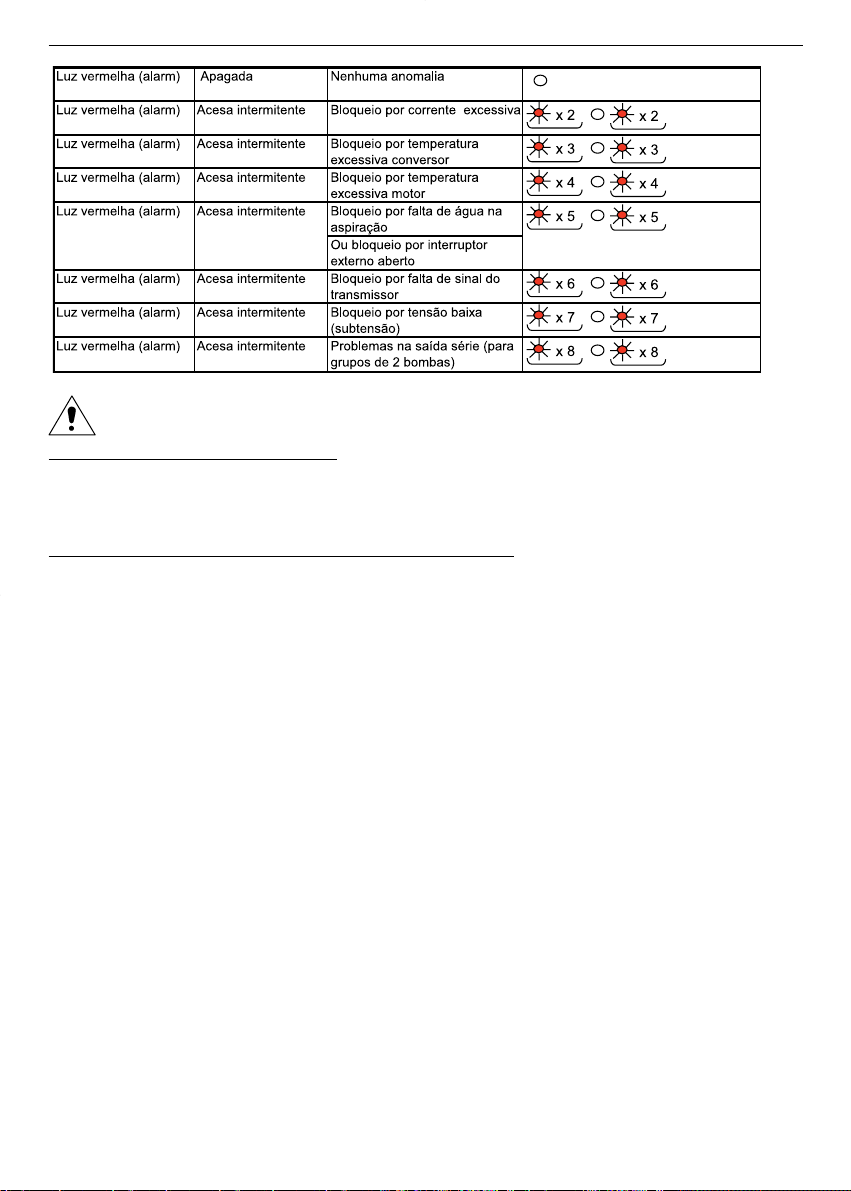
Prestar atenção ao intervir no sistema, pois pode arrancar de novo automaticamente.
Bloqueio por falta de água na aspiração
Na presença de bloqueio pela falta de água na aspiração, o sistema arranca de novo automaticamente
só se o dispositivo externo habilitar novamente o funcionamento (flutuador ou pressóstato ou
nterruptor ➞ capítulos 6.2.7 e 6.2.8).
Bloqueio por outras razões excepto a falta de água na aspiração
Em todos estes casos o sistema arranca de novo automaticamente depois de 20 segundos. Se persistir
a causa da anomalia, depois de três tentativas de arranque, o sistema bloqueia-se definitivamente.
Para voltar a ajustar a zero a situação, é preciso desligar a tensão do sistema durante pelo menos um
minuto.
Se depois de um alarme passarem pelo menos 10 minutos sem alguma outra anomalia, o contador de
alarmes é ajustado a zero e são novamente possíveis três tentativas.
No caso de duas ou mais causas de alarme simultâneas (por exemplo temperatura excessiva do motor e
falta de água), é assinalada sempre e só a primeira que consegue fazer chegar o sinal para a ficha de
controlo.
ATENÇÃO ! O conversor não tem uma memória indelével dos alarmes activados. Portanto, aconselha-
se a observar com atenção a frequência da intermitência antes de desligar a tensão do sistema TKS
Para mais informações, consultar os capítulos 8.1 e 12.
77
pt
TKS_M0026_A_OT.XLS

8.2 Prospecto
INCONVENIENTE CAUSA PROVÁVEL REMÉDIO POSSÍVEL
A electrobomba não arranca. Falta a alimentaçáo eléctrica. Restaurar a alimentaçáo.
O interruptor geral está activado.
Luz verde apagada Activou-se o interruptor Restabelecer o interruptor
magnetotérmico
A electrobomba náo arranca, ou
pára se estava a funcionar. *** = 2 intermitÍncias
O interruptor geral está activado. Sobrecarga do motor Verificar as condições de
Luz verde acesa of the electric pump
Luz vermelha acesa Estator do motor danificado Controlar o motor
(***intermitências) *** = 3 intermitÍncias
Temperatura excessiva do conversor Controlar que nada dificulte o
arrefecimento correcto do
conversor
*** = 4 intermitÍncias
Temperatura excessiva do motor Verificar as condições de
(se presente a protecção PTC na trabalho da electrobomba
placa de bornes)
*** = 5 intermitÍncias
Eventual protecção contra o Controlar o nível da água
funcionamento a seco activada Controlar o dispositivo externo
e os relativos cabos de ligação
*** = 6 intermitÍncias
Problemas no transmissor Controlar o transmissor e o
de pressão relativo cabo de ligação
*** = 7 intermitÍncias
A tensão de alimentação è
baixa demais
Pontos de utilização fechados Perdas de água através da válvula Controlar a instalação para
Electrobomba em funcionamento anti-retorno ou na instalação localizar as perdas. Reparar ou
com aumento e diminuição substituir os componentes.
cíclicos da velocidade Eventual autoclave de dimensıes Verificar as condições de
Luz verde acesa reduzidas trabalho da electrobomba
Luz amarela acesa Eventual autoclave com a Substituir a membrana
Luz vermelha apagada membrana partida
Ajuste do ponto de trabalho Voltar a ajustar o sistema
no adequado à instalação (valor
superior à pressão que pode ser
fornecida pela bomba)
Pontos de utilização abertos Ajuste do ponto de trabalho Voltar a ajustar o sistema
A electrobomba não arranca não adequado à instalação (valor
Luz verde acesa igual a zero)
Luz amarela apagada
Luz vermelha apagada
A electrobomba está a funcionar Ajuste do ponto de trabalho não Voltar a ajustar o sistema
Presença de vibrações na adequado para a instalação (valor
bomba ou perto da bomba inferior à pressão mínima que
pode ser fornecida pela bomba)
A electrobomba está a funcionar Possíveis problemas no flutuador Controlar o flutuador e o tanque
Arranques e paragens frequentes posto no tanque de aspiração
A electrobomba está funcionar Possíveis problemas no Controlar a ligaço hidráulica entre
sempre à velocidade máxima transmissor de pressão o system transmissor e a
instalação
78
pt

Activa-se a protecção geral Curto-circuito Verificar os cabos de ligação
da instalação
Activa-se a protecção diferencial da Dispersão à terra Verificar o isolamento da
instalação (disjuntor geral) electrobomba e dos cabos
9. Peças de reposição Informações para o encarregado da manutenção
Indicar sempre o exacto código de identificação do modelo, junto com o número de fabrico, caso sejam
pedidas informações técnicas ou peças de reposição ao nosso Serviço de Venda e Assistência.
Utilizar apenas peças de origem para substituir os eventuais componentes avariados.
O emprego de peças de reposição não adequadas pode provocar funcionamentos anómalos e
perigos para as pessoas e as coisas.
10. Eliminação Informações para o instalador e o encarregado da manutenção
Após a instalação, eliminar a embalagem de acordo com as leis em vigor, se possível voltar a utilizar a
embalagem para outros usos.
Se resultar necessário eliminar o produto e por conseguinte desmontá-lo, é obrigatório respeitar as leis
em vigor para a recolha selectiva dos resíduos.
11. Garantia
Para quaisquer informações, ter como referência a documentação contratual de venda.
79
pt

nl
« Vertaling van de oorspronkelijke gebruiksaanwijzing »
Nederlands
1. Algemeen
Deze handleiding is bedoeld om informatie te verstrekken die onmisbaar is voor de installatie, het gebruik en het onderhoud van de TEKNOSPEED omzetter in combinatie met een LOWARA elektropomp.
Deze handleiding moet aandachtig gelezen worden voordat het product in gebruik genomen
wordt.
Door onjuist gebruik kunnen er gevaarlijke situaties ontstaan met schade aan personen en
voorwerpen en dit kan eveneens tot het verlies van het recht op garantie leiden.
Voor informatie over de elektropompen moeten de betreffende gebruiksaanwijzingen geraadpleegd worden.
De aanwijzingen en de voorschriften die hieronder verstrekt worden zijn van toepassing op de standaard
uitvoering.
Voor wat betreft de varianten en de kenmerken van speciale uitvoeringen moet de verkoopdocumentatie
geraadpleegd worden.
Bij het aanvragen van technische informatie of bij het bestellen van reserveonderdelen bij onze verkoopen serviceafdeling moet altijd de juiste identificatiecode van het model tezamen met het constructienummer vermeld worden.
Ten aanzien van aanwijzingen, situaties en gebeurtenissen die niet in deze handleiding en niet in de
verkoopdocumentatie aan de orde komen moet contact opgenomen worden met onze dichtstbijzijnde
servicedienst.
2. Voorinspectie
2.1 Visuele controle
Bij aflevering moet gecontroleerd worden of de verpakking intact is.
Als de verpakking beschadigd is moet het product uit de verpakking gehaald worden en visueel gecontroleerd worden of het product tijdens het transport niet beschadigd is. Indien het product beschadigingen vertoont, moet onze dealer hier binnen 8 dagen na aflevering van op de hoogte gesteld worden.
2.2 Hantering en opslag
Het product wordt in een kartonnen doos geleverd. Tijdens het transport en de opslag moet de doos beschut worden voor vocht, warmtebronnen en eventuele mechanische schade (stoten, vallen enz.). Het
product moet voorzichtig opgehesen en verplaatst worden waarbij geschikte hef- en hijswerktuigen gebruikt moeten worden.
Voor nadere informatie zie hoofdstuk 4.
3. Gebruiksdoeleinden
Het TKS systeem bestaat uit een driefase elektropomp, de monofase TEKNOSPEED omzetter en een
elektronische druktransmitter (ook bekend als druksensor).
De monofase TEKNOSPEED omzetter is geschikt voor de besturing van een driefase elektropomp in overeenstemming met de voorwaarden die in deze handleiding staan en de regeling van de voedingsspanning en -frequentie die op het typeplaatje aangegeven is.
De omzetter zorgt ervoor dat de pomp zodanig afgesteld wordt dat er bij de levering van opbrengst een
constante druk verkregen wordt op basis van het signaal dat afkomstig is van de elektronische druktransmitter.
Het TKS systeem kan gebruikt worden voor transport van water voor huishoudelijk gebruik, beregening
en drukverhoging.
Voor nadere informatie zie hoofdstuk 12.
80

4. Gebruiksbeperkingen
Opslag:
• Omgevingstemperatuur: van -5°C tot +40°C.
Gebruik:
Voor informatie over de elektropompen moeten de betreffende gebruiksaanwijzingen geraadpleegd worden.
4.1 TKS systeem (TEKNOSPEED geïnstalleerd op de elektropomp)
Het product mag niet in stoffige omgevingen gebruikt worden waar zuren, corrosieve en/of ontvlambare gassen enz. voorhanden zijn.
De elektropomp mag ook niet gebruikt worden om gevaarlijke of ontvlambare vloeistoffen te verpompen.
• Omgevingstemperatuur: van +0°C tot +40°C
• Maximum relatieve luchtvochtigheid: 50% bij + 40°C mits er geen condensatieverschijnselen
zijn
• Maximum hoogte boven de zeespiegel: 1000 meter
• Beschermingsgraad: IP55 (indien geïnstalleerd op motoren met beschermingsgraad IP55 of
hoger)
• Maximum bedrijfsdruk: zie de specifieke gebruiksaanwijzing van de elektropomp
Bij de standaard uitvoering is een transmitter met volle schaaluitslag van 10 bar bij de levering
inbegrepen (paragraaf 4.2)
• Temperatuur van de verpompte vloeistof: van + 1°C tot + 40°C
• Aard van de verpompte vloeistof: water zonder chemisch agressieve bestanddelen en zweven
de vaste delen
• Maximum nominaal vermogen van de elektropomp die met de omzetter gecombineerd kan
worden: 1,1 kW
• Voedingsspanning van de omzetter: 1 x 230 V ± 10% 50/60 Hz
• Uitgangsspanning van de omzetter (stemt overeen met de voedingsspanning van de motor):
3 x 230 V ± 10% 12-50 Hz (variabele waarden al naargelang de spannings-/frequentiecurve
van de omzetter)
• Nominale ingangsstroom in de omzetter: 6,8 A
• Nominale uitgangsstroom uit de omzetter: 4,6 A
• Maximaal aantal keer starten per uur, op gelijk verdeelde wijze: zie de gebruiksaanwijzing van
de elektropomp.
4.2 Druktransmitter
De sensor van deze transmitter is een drukgevoelig element van piëzoweerstandssilicium, die gemonteerd is op een kleine flexibele printplaat (TAB) en die in een oliekamer ondergedompeld is. De druk
wordt via een stalen membraan die zich in de oliekamer bevindt naar het element gestuurd.
• Drukbereik: van 0 tot 10 bar
• Voeding: 21 Vdc van TEKNOSPEED
• Uitgaand signaal: van 4 tot 20 mA
• Aansluiting:
1
/4” mannetje, van vernikkeld messing
• Elektrische connector: van het uitneembare type, geleverd met twee meter afgeschermde kabel
• Beschermingsgraad: IP55.
In geval van andere omgevingscondities moet contact opgenomen worden met onze verkoop- en servicedienst.
81
nl

5. Installatie
Informatie voor de installateur
De installatiewerkzaamheden mogen uitsluitend door vakbekwaam en geschoold personeel uitgevoerd worden.
Er moet geschikt gereedschap en geschikte beschermingsmiddelen gebruikt worden. De veiligheidsvoorschriften moeten in acht genomen worden.
Vóór installatie moet deze gebruiksaanwijzing en de gebruiksaanwijzing van de elektropomp
aandachtig gelezen worden.
Indien het product duidelijke tekenen van beschadiging vertoont dan mag het product in geen geval
geïnstalleerd worden en moet er contact opgenomen met de servicedienst.
Het product moet op een plaats die beschut is voor vorst en ongunstige weersomstandigheden
geïnstalleerd worden, waarbij de gebruiksbeperkingen in acht genomen moeten worden en op
een dusdanige manier dat er gewaarborgd wordt dat de motor in voldoende mate gekoeld wordt.
Voor nadere informatie zie hoofdstuk 4 en 12.
De geldende veiligheids- en ongevalpreventievoorschriften moeten nauwgezet in acht genomen
worden.
6. Inwerkingstelling Informatie voor de installateur
De werkzaamheden met het oog op de inwerkingstelling mogen uitsluitend door vakbekwaam en
geschoold personeel uitgevoerd worden. Er moet geschikt gereedschap en geschikte beschermingsmiddelen gebruikt worden. De veiligheidsvoorschriften moeten in acht genomen worden.
Vóór de inwerkingstelling moet deze gebruiksaanwijzing en de gebruiksaanwijzing van de elek-
tropomp aandachtig gelezen worden.
6.1Hydraulische aansluiting van de elektropomp
De hydraulische aansluitingen moeten volgens de geldende normen en wettelijke voorschriften
tot stand gebracht worden.
Het product kan gebruikt worden door het product rechtstreeks op het waterleidingnet aan te sluiten of
door water uit een eerste opvangreservoir te tappen.
Als het product op het waterleidingnet aangesloten wordt moeten de geldende voorschriften die uitgevaardigd zijn door de bevoegde instanties (Gemeente, waterleidingbedrijf enz.) in acht genomen worden. Er wordt geadviseerd om een drukregelaar aan de aanzuigzijde te installeren om de elektropomp uit
te schakelen als de druk in het waterleidingnet laag is (beveiliging tegen drooglopen).
Er moet gecontroleerd worden of de druk van het waterleidingnet en de maximum druk van de
pomp bij elkaar opgeteld niet meer bedraagt dan de maximum toegestane werkdruk (nominale
druk PN) van de pomp.
Als er bijvoorbeeld een pomp CA 70/33 in het systeem aanwezig is dan kan hier het volgende uit op gemaakt worden:
Maximum opvoerhoogte van de pomp:
43 meter (gelijk aan een sluitdruk van ongeveer 4,3 bar)
Maximum toegestane werkdruk:
8 bar (PN 8)
Druk van het waterleidingnet (er moet rekening gehouden worden met de maximum waarde):
1,5 bar
Maximum werkdruk die hieruit resulteert:
4,3 + 1,5 = 5,8 lager dan de grens van 8 bar
82
nl

Als er een eerste opvangreservoir gebruikt wordt moet er een vlotterschakelaar geïnstalleerd worden om
de elektropomp uit te schakelen wanneer er geen water is (beveiliging tegen drooglopen).
Het is verplicht om een manometer aan de perszijde te installeren omdat het nodig kan zijn dat
de fabrieksmatige instelling al naargelang de werkelijke installatieomstandigheden veranderd
moet worden.
Normaal wordt het systeem aangevuld met de installatie van flexibele slangen aan de aanzuig- en perszijde, afsluiters op de aanzuig- en persleiding, balkeerklep en membraantank. Als men wil vermijden om
het systeem te legen om de membraantank, de manometer of de druktransmitter eventueel te vervangen
wordt geadviseerd om afsluiters te installeren.
Indien de balkeerklep aan de perszijde van de pomp geïnstalleerd wordt moet de druktransmitter na de
klep geplaatst worden. Er wordt geadviseerd om een kraan te installeren die tijdens het instellen van het
TKS systeem gebruikt moet worden (paragraaf 6.3.3) als er niet reeds een tappunt in de buurt van de
pomp aanwezig is.
Voor nadere informatie zie hoofdstuk 12.
6.1.1 Drukreservoir (tank met membraan)
Aan de perszijde van de elektropomp moet een tank met een membraan geïnstalleerd worden om ervoor
te zorgen dat de installatie onder druk blijft staan ook als er niet om water gevraagd wordt om continue
werking van de pomp te vermijden.
Met de TEKNOSPEED omzetter is het niet nodig om een grote tank toe te passen omdat het voldoende is
dat de nominale inhoud, in liter, ervan gelijk is aan ten minste 5% van de maximum opbrengst (liter per
minuut) van de pomp met een nominale capaciteit van minimaal 8 liter.
Voorbeeld: maximum opbrengst van de pomp = 60 liter per minuut
nominale inhoud van het reservoir = 60 x 0,05 = 3 liter ➞ 8 liter
maximum opbrengst van de pomp = 150 liter per minuut
nominale inhoud van het reservoir = 150 x 0,05 = 7,5 liter ➞ 8 liter
Er moet nagegaan worden of de tank in staat is om de maximum druk van de installatie te verdra-
gen.
Alvorens de tank op de installatie aan te sluiten moet de juiste voordruk gecontroleerd worden en afgesteld worden.
Als de tank reeds aangesloten is moet de installatie geleegd worden alvorens de voordruk te controleren
en af te stellen. Om dit te vermijden wordt geadviseerd om een afsluiter tussen de aansluiting op de tank
en de leiding van de installatie te installeren.
Om de voordrukwaarde van de tank te bepalen kan de volgende formule toegepast worden:
indien in bar ➞ werkdruk – 0,2 = voordruk
indien in kPa ➞ werkdruk – 20 = voordruk
6.2 Elektrische aansluiting van de elektropomp
De elektrische aansluitingen moeten volgens de geldende voorschriften en wettelijke bepalingen
uitgevoerd worden.
Er moet gecontroleerd worden of het type voedingsnet, de voedingsspanning en -frequentie ove-
reenstemt met de nominale gegevens van het TKS systeem die op het typeplaatje staan. Er moet
voor een geschikte algemene beveiliging tegen kortsluiting op de elektrische leiding gezorgd
worden.
LET OP: Hoewel het TKS systeem voorzien is van een monofase voeding is de motor van de pomp altijd
een driefase draaistroommotor met een aansluitwaarde van 230V. De ontbrekende fases worden gecreëerd door de omzetter. Voor nadere informatie zie hoofdstuk 12.
83
nl

Alvorens aan het werk te gaan moet gecontroleerd worden of alle aansluitingen (en dit geldt ook
voor de potentiaalvrije aansluitingen) spanningsvrij zijn. De TEKNOSPEED omzetter moet altijd
van de elektrische voeding losgekoppeld worden alvorens enige werkzaamheden aan de elektri-
sche of mechanische onderdelen van de installatie uit te voeren.
Na het loskoppelen van het voedingsnet moet minimaal 1 minuut gewacht worden alvorens iets
aan de TEKNOSPEED te doen zodat de condensatoren van het inwendige circuit de gelegenheid
hebben om te ontladen.
6.2.1 Thermische magneetschakelaar met aardlekbeveiliging
Indien de geldende plaatselijke elektrische voorschriften de installatie van een thermische magneetschakelaar met aardlekbeveiliging voorschrijven dan moet gecontroleerd worden of deze geschikt is voor
het type installatie. De schakelaars die geschikt zijn hebben een karakteristieke curve voor wissellekstroom en éénrichtingsknoppen (type A of C).
Zij kunnen onderscheiden worden aan de aanwezigheid van het volgende symbool
6.2.2 Uitvoering met kabel en stekker
Het TKS systeem wordt geleverd met een voedingskabel met een stekker.
De pomp moet zodanig geïnstalleerd worden dat de stekker en de betreffende contactdoos altijd
goed bereikbaar zijn indien het systeem uitgeschakeld moet worden.
In geval van beschadiging van de voedingskabel moet de kabel bij een servicecentrum of in ieder geval
door vakmensen vervangen worden.
6.2.3 Inlaatfilter
De TEKNOSPEED omzetter beschikt over een inlaatfilter dat in overeenstemming is met de EMC richtlijn.
6.2.4 Beveiliging tegen overbelasting van de motor
De TEKNOSPEED omzetter heeft een ingebouwde beveiliging tegen overbelasting die absolute bescherming biedt als hij gecombineerd wordt met motoren die een nominaal vermogen hebben dat gelijk is aan
dat van de omzetter. Voor motoren met een lager vermogen wordt een extra beveiliging toegepast (paragraaf 6.2.5)
6.2.5 Beveiliging tegen oververhitting van de motor (PTC)
Bij sommige modellen motoren kan een beveiliging (thermistor) voorhanden zijn die een aanvulling vormt
op de beveiliging tegen overbelasting die in de omzetter ingebouwd is. De thermistor (PTC) is aan de onderkant van de klemmenplaat bevestigd en is door middel van kabeltjes en minifastons aangesloten op
de besturingsprintplaat. De betreffende dipschakelaar zal op de stand PTC Y staan.
Voor nadere informatie zie hoofdstuk 12.
6.2.6 Beveiliging tegen oververhitting van de omzetter
De TEKNOSPEED omzetter beschikt over een ingebouwde beveiliging tegen oververhitting.
6.2.7 Beveiliging tegen drooglopen (vlotterschakelaar)
De TEKNOSPEED omzetter kan aangesloten worden op een uitwendige inrichting die bescherming tegen
drooglopen van de pomp biedt (paragraaf 6.1). De meest traditionele methode is de toepassing van een
vlotterschakelaar die in de aanzuigbak geplaatst wordt.
Om de kabel van de uitwendige inrichting aan te sluiten moet de koeler van de omzetter met een inbussleutel nr. 5 (maximum aanhaalmoment 6 Nm) verwijderd worden. Daarna moet de koeler ondersteboven
neergelegd worden waarbij op de aansluitingen op de uitneembare klemmenplaat gelet moet worden.
Het kan nodig zijn om de klemmenplaat eruit te halen. Een plug M16 x 1,5 moet door één van de meegeleverde kabelklemmen vervangen worden. De kabel van de vlotterschakelaar moet men erdoor laten
lopen en deze moet aangesloten worden op de klemmen LOW 1 en LOW 2 (geschikt voor geleiders van
0,5-1 mm2). Daarna moet het kabelklemplaatje vastgedraaid worden en moet de kabelklem aangedraaid worden om de kabel vast te zetten. Er kan een drukregelaar gebruikt worden waarvan het contact
opengaat als de druk onder de instelwaarde daalt indien de aanzuiging van de pomp op het waterleidingnet aangesloten wordt.
84
nl

Als er geen inrichting gebruikt wordt moet men de jumpers op de twee klemmen laten zitten.
De schroevendraaier met een platte kling (2,5 mm) die bij het TKS systeem inbegrepen is moet
gebruikt worden om de aansluitingen op de klemmenplaat van de omzetter tot stand te brengen.
Voor nadere informatie zie hoofdstuk 12.
6.2.8 Uitwendige inschakeling
In plaats van de vlotterschakelaar (paragraaf 6.2.7) kan een schakelaar aangesloten worden. Met deze
uitwendige inrichting kan het systeem in- of uitgeschakeld wordt. Er wordt geadviseerd om een afgeschermde kabel te gebruiken. De kabel moet zodanig gestript worden dat de betreffende afscherming in
aanraking komt met het kabelklemplaatje.
De schroevendraaier met een platte kling (2,5 mm) die bij het TKS systeem inbegrepen is moet
gebruikt worden om de aansluitingen op de klemmenplaat van de omzetter tot stand te brengen.
Voor nadere informatie zie hoofdstuk 12.
6.2.9 Alarmrelais
De TEKNOSPEED omzetter heeft een contact ter beschikking om een uitwendige signalering van een
blokkering of een storing te verkrijgen.
Dit contact is gesloten als
• de pomp door één van de volgende oorzaken uitgeschakeld is:
stroomuitval
overbelasting van de motor (paragraaf 6.2.5)
oververhitting van de motor (paragraaf 6.2.6)
oververhitting van de omzetter (paragraaf 6.2.7)
Sensor defect of niet aangesloten (paragraaf 6.2.11)
• water in aanzuiging ontbreekt (paragraaf 6.2.8 en 6.2.9)
Om de kabel aan te sluiten moet de koeler van de omzetter met een inbussleutel nr. 5 (maximum
aanhaalmoment 6 Nm) verwijderd worden. Daarna moet de koeler ondersteboven neergelegd worden
waarbij op de aansluitingen op de uitneembare klemmenplaat gelet moet worden. Het kan nodig zijn om
de klemmenplaat eruit te halen. Een plug M16 x 1,5 moet door één van de meegeleverde kabelklemmen
vervangen worden. De kabel van de vlotterschakelaar moet men erdoor laten lopen en deze moet aangesloten worden op de klemmen COM en NC (geschikt voor geleiders van 0,5-1 mm2). Daarna moet het
kabelklemplaatje vastgedraaid worden en moet de kabelklem aangedraaid worden om de kabel vast te
zetten.
Er wordt geadviseerd om een afgeschermde kabel te gebruiken. De kabel moet zodanig gestript worden
dat de betreffende afscherming in aanraking komt met het kabelklemplaatje.
De schroevendraaier met een platte kling (2,5 mm) die bij het TKS systeem inbegrepen is moet
gebruikt worden om de aansluitingen op de klemmenplaat van de omzetter tot stand te brengen.
Voor nadere informatie zie hoofdstuk 12.
6.2.10 Seriële interface
De TEKNOSPEED omzetter beschikt over een seriële interface die alleen bij pompsystemen met twee
pompen toegepast kan worden.
Er mogen geen draden op de klemmen COM, TX, RX van de seriële interface aangesloten wor-
den.
Voor nadere informatie zie hoofdstuk 12.
6.2.11 Druktransmitter
Het TKS systeem wordt geleverd met een druktransmitter die aangesloten is op de klemmenplaat van de
TEKNOSPEED omzetter.
De transmitter is voorzien van een 2 meter lange afgeschermde kabel. Als de kabel opgeborgen moet
worden mag de kabel niet opgerold worden maar moet hij als een harmonica gevouwen worden.
Voor nadere informatie zie hoofdstuk 12.
85
nl

6.2.12 Regeldipschakelaars
De TEKNOSPEED omzetter beschikt over een aantal microschakelaars (dipschakelaars) die de werkingscyclus ervan bepalen.
De fabrieksmatige instelling mag niet veranderd worden. Hierdoor kan het systeem of de installa-
tie waar het systeem op geïnstalleerd is beschadigd worden.
Voor nadere informatie zie hoofdstuk 12.
6.3 Opstarten
6.3.1 Aanzuiging
De gebruiksaanwijzing van de elektropomp moet aandachtig gelezen worden.
De pomp en de aanzuigleidingen moeten alvorens het systeem in werking te stellen met water
gevuld worden. Door drooglopen kan de pomp beschadigd worden.
Het systeem moet in werking gesteld worden terwijl de afsluiter op de persleiding gesloten is. Daarna
moet de afsluiter geleidelijk geopend worden. Als alle lucht uit de leiding ontsnapt is zal de pomp goed
en geruisloos functioneren.
6.3.2 Controle van de draairichting van de motor
Het is niet nodig om de draairichting van de motor te controleren omdat deze reeds in de fabriek vastgesteld is.
6.3.3 Instelling van de werkdruk
Er moet een manometer aan de perszijde geïnstalleerd worden omdat het noodzakelijk kan zijn
om de fabrieksmatige instelwaarde op basis van de werkelijke installatieomstandigheden en de
eisen van het systeem te veranderen.
Het TKS systeem is reeds voorzien van een fabrieksinstelling waardoor het gebruik ervan mogelijk is.
De drukwaarde kan als volgt op basis van de werkelijke eisen van het systeem veranderd worden:
• De drukwaarde verhogen
- Er moet gecontroleerd worden of de installatie onder druk staat, of er geen verbruikers open zijn en of
de pomp stil staat. Indien er een verbruiker open is kan de afsluiter die na de pomp geplaatst is
gesloten worden.
- Het kapje waarmee de regelschroef afgedekt is moet losgedraaid worden.
- Daarna moet de regelschroef met een schroevendraaier langzaam naar rechts gedraaid worden.
De schroevendraaier met platte kling (2,5 mm) die bij het TKS systeem inbegrepen is moet ge-
bruikt worden. De regelschroef heeft een beperkte spoed, minder dan een slag, tussen de mini-
mum waarde (0 bar) en de maximum waarde (10 bar). De schroef mag niet buiten deze grenzen
geforceerd worden omdat de schroef hierdoor beschadigd kan worden.
- De pomp start.
- De drukwaarde moet van de manometer afgelezen worden en men moet aan de regelschroef
blijven draaien totdat de wijzer van de manometer op de gewenste waarde staat.
- Er moet gecontroleerd worden of de druk zich op de gewenste waarde gestabiliseerd heeft.
- Indien nodig moeten er kleine veranderingen uitgevoerd worden door de regelschroef naar rechts of
naar links te draaien. Als de insteldruk verlaagd moet worden wordt geadviseerd om een verbruiker
iets te openen (zie de volgende paragraaf "De drukwaarde verlagen").
Er moet gecontroleerd worden of de nieuwe waarde die gekozen is binnen het opvoerhoogtebe-
reik is dat op het typeplaatje van het TKS systeem staat.
- De pomp stopt na ongeveer 60 seconden. De stopdruk kan iets hoger zijn dan de gewenste
waarde (paragraaf 6.4.1).
86
nl

• De drukwaarde verlagen
- Er moet gecontroleerd worden of de installatie onder druk staat, of er geen verbruikers open zijn en
of de pomp stil staat.
- Het kapje waarmee de regelschroef afgedekt is moet losgedraaid worden.
- De afsluiter die na de pomp geplaatst is moet open gelaten worden.
- Daarna moet er een verbruiker of de testkraan (paragraaf 6.1) iets geopend worden en moet men
de druk langzaam laten zakken.
- De pomp start.
- Daarna moet de regelschroef met een schroevendraaier langzaam naar links gedraaid worden.
De schroevendraaier met platte kling (2,5 mm) die bij het TKS systeem inbegrepen is moet ge-
bruikt worden. De regelschroef heeft een beperkte spoed, minder dan een slag, tussen de mini-
mum waarde (0 bar) en de maximum waarde (10 bar). De schroef mag niet buiten deze grenzen
geforceerd worden omdat de schroef hierdoor beschadigd kan worden.
- De drukwaarde moet van de manometer afgelezen worden en men moet aan de regelschroef
blijven draaien totdat de wijzer van de manometer op de gewenste waarde staat.
- Er moet gecontroleerd worden of de druk zich op de gewenste waarde gestabiliseerd heeft.
- Indien nodig moeten er kleine veranderingen uitgevoerd worden door de regelschroef naar rechts
of naar links te draaien.
Er moet gecontroleerd worden of de nieuwe waarde die gekozen is binnen het opvoerhoogtebe-
reik is dat op het typeplaatje van het TKS systeem staat.
- De pomp stopt na ongeveer 60 seconden. De stopdruk kan iets hoger zijn dan de gewenste
waarde (paragraaf 6.4.1).
Voor nadere informatie zie hoofdstuk 12.
6.3.4 Indicatielampjes
Op de sticker die bovenop de koeler aangebracht is zijn drie ledindicatielampjes aangebracht die de volgende functies hebben:
Groen lampje continu aan Power Duidt erop dat de stroom naar het TKS systeem ingeschakeld is
Geel lampje continu aan Run Duidt erop dat de pomp in werking is
Rood lampje knippert Alarm Duidt erop dat er een alarmtoestand opgetreden is
In geval van alarm zal het rode lampje met een variabele frequentie knipperen al naargelang de oorzaak
waardoor het systeem geblokkeerd is. Behalve in geval van ontbreken van water in de aanzuiging zal het
systeem in alle andere gevallen na 20 seconden automatisch weer starten. Als de oorzaak van de storing
voortduurt zal het systeem na drie startpogingen definitief geblokkeerd worden behalve in geval van ontbreken van water in de aanzuiging.
Voor nadere informatie zie paragraaf 8.1 en hoofdstuk 12.
6.4 Beschrijving van het product Informatie voor de gebruiker
Het TKS systeem bestaat uit een elektropomp die aangedreven wordt door middel van een elektronisch
automatisch besturingssysteem (frequentieomzetter die ook bekend is als toerenregelaar) waarmee het
mogelijk is om een constante druk te leveren waarbij de opbrengst op basis van de eisen verminderd of
vermeerderd wordt.
6.4.1 Werking
Het elektronische automatische besturingssysteem neemt het signaal dat afkomstig is van een druksensor en vergelijkt dit met de ingestelde waarde.
Terwijl de installatie onder druk staat, staat de pomp stil. De daling van de druk die teweeggebracht
wordt door het tappen van water door de verbruiker leidt tot vermindering van het signaal waardoor de
pomp via het besturingssysteem gestart wordt en waarbij de snelheid zodanig geregeld wordt dat de referentiedruk (of de werkdruk) weer hersteld wordt. Als het tappen van water toeneemt zorgt het besturingssysteem ervoor dat de snelheid van de pomp verhoogd wordt; als het tappen van water afneemt
zorgt het besturingssysteem ervoor dat de snelheid van de pomp verlaagd wordt. Als de maximum watercapaciteit die door de pomp geleverd kan worden bereikt wordt laat het besturingssysteem de pomp
87
nl

op zijn maximum nominale snelheid werken.
In geval van stijging van de druk, wat teweeggebracht wordt door een vermindering van het tappen van
water, neemt het signaal dat afkomstig is van de sensor toe waardoor de snelheid van de pomp via het
besturingssysteem verlaagd wordt.
Als het tappen van water plotseling onderbroken wordt (bijvoorbeeld door snel dichtdraaien van de kranen) laat het besturingssysteem de pomp op een minimum snelheid functioneren en stopt de pomp vervolgens na ongeveer 60 seconden. In dit geval stemt de stopdruk overeen met de ingestelde waarde.
Als de onderbreking langzaam plaatsvindt laat het systeem de pomp op een iets hogere druk functioneren (met de volle schaaluitslag van de transmitter gelijk aan 10 bar ➞ + 0,2 bar) en zorgt het systeem er
vervolgens voor dat de pomp na ongeveer 60 seconden gestopt wordt als er geen water getapt wordt.
Als de stroom ingeschakeld is, is het groene lampje (Power) aan.
Als de pomp ingeschakeld is dan is het gele lampje (Run) aan.
In geval van blokkering of abnormale werking is het rode lampje (Alarm) aan.
In geval van alarm zal het rode lampje met een variabele frequentie knipperen al naargelang de oorzaak
waardoor het systeem geblokkeerd is. Behalve in geval van ontbreken van water in de aanzuiging zal het
systeem in alle andere gevallen na 20 seconden automatisch weer starten. Als de oorzaak van de storing
voortduurt zal het systeem na drie startpogingen definitief geblokkeerd worden behalve in geval van ontbreken van water in de aanzuiging.
Voor alle afstel- en/of onderhoudswerkzaamheden moet men zich tot vakbekwaam en geschoold
personeel wenden. Er mag niet geprobeerd worden om de afstellingen te veranderen en het be-
sturingssysteem mag ook niet opengemaakt worden.
Vóór gebruik moeten de gebruiksaanwijzingen aandachtig gelezen worden en zij moeten boven-
dien goed bewaard worden.
De schroevendraaier die bij het TKS systeem geleverd is moet goed bewaard worden.
7. Onderhoud Informatie voor de onderhoudsmonteur
Bij alle voorkomende werkzaamheden moeten de volgende voorschriften in acht genomen worden.
Onderhoudswerkzaamheden mogen alleen door vakbekwaam personeel uitgevoerd worden.
Alvorens met welke onderhoudswerkzaamheden dan ook beginnen moet gecontroleerd worden
of alle aansluitingen (en dit geldt ook voor de potentiaalvrije aansluitingen) spanningsvrij zijn.
De TEKNOSPEED omzetter moet altijd van de elektrische voeding losgekoppeld worden alvorens
enige werkzaamheden aan de elektrische of mechanische onderdelen van de installatie uit te
voeren.
Na het loskoppelen van het voedingsnet moet minimaal 1 minuut gewacht worden alvorens iets
aan de TEKNOSPEED te doen zodat de condensatoren van het inwendige circuit de gelegenheid
hebben om te ontladen.
Deze gebruiksaanwijzing, de gebruiksaanwijzing van de elektropomp en van de eventuele tank
met membraan moet aandachtig gelezen worden.
7.1 Gewoon onderhoud
Het TKS systeem vergt geen routineonderhoud mits het systeem binnen de in hoofdstuk 4 bepaalde
grenzen toegepast wordt.
De pompen vergen geen routineonderhoud (zie de gebruiksaanwijzing van de pomp).
De voorvulling van lucht van de tank indien aanwezig moet minimaal één keer per jaar gecontroleerd
worden (paragraaf 6.1.1).
88
nl

7.2 Buitengewoon onderhoud
Er moet geschikt gereedschap en geschikte beschermingsmiddelen gebruikt worden. De veili-
gheidsvoorschriften moeten in acht genomen worden. De pompen moeten voorzichtig opgehe-
sen en verplaatst worden waarbij gebruik gemaakt moet worden van geschikte hijs- en hefwerk-
tuigen.
Er mogen alleen originele reserveonderdelen gebruikt worden om eventuele versleten of defecte
onderdelen te vervangen.
LET OP!
Hoewel het TKS systeem voorzien is van een monofase voeding is de motor van de pomp altijd een driefase draaistroommotor met een aansluitwaarde van 230V. De ontbrekende fases worden gecreëerd door
de omzetter. Voor nadere informatie zie hoofdstuk 12.
8. Lokaliseren van storingen Informatie voor de gebruiker en de onderhoudsmonteur
Deze gebruiksaanwijzing en de gebruiksaanwijzing van de elektropomp en van de eventuele
tank met membraan moet aandachtig gelezen worden.
Eventuele werkzaamheden mogen alleen door vakbekwaam personeel uitgevoerd worden.
Voor nadere informatie zie hoofdstuk 7 en 12.
8.1 Lichtsignalen
8.1.1 Werkingssignalen
Deze essentiële signalen worden aangevuld door de alarmsignalen. Er kunnen dus combinaties van signalen zijn zoals groen lampje aan (stroom ingeschakeld), geel lampje uit (pomp uitgeschakeld) en rood
lampje knippert (alarm).
89
nl
TKS_M0025_A_OT.XLS

8.1.2 Alarmsignalen
In geval van alarm zal het rode lampje met een variabele frequentie knipperen (knipperen - pauze - knipperen) al naargelang de oorzaak waardoor het systeem geblokkeerd is.
Er moet goed opgelet worden als men aan het systeem werkt omdat het systeem automatisch
weer kan starten.
Blokkering vanwege ontbreken van water in de aanzuiging
In geval van blokkering vanwege het ontbreken van water in de aanzuiging zal het systeem automatisch
weer starten alleen als de uitwendige inrichting (vlotterschakelaar, drukregelaar of schakelaar ➞ para-
graaf 6.2.7 en 6.2.8) de werking weer vrijgeeft.
Blokkering om andere reden met uitzondering van ontbreken van water in de aanzuiging
In al deze gevallen zal het systeem na 20 seconden automatisch weer starten. Als de oorzaak van de
storing voortduurt zal het systeem na drie startpogingen definitief geblokkeerd worden.
Om de situatie te herstellen moet de stroom van het systeem minimaal één minuut lang uitgeschakeld
worden.
Als er na een alarm ten minste 10 minuten voorbij gegaan zijn zonder dat er een andere storing optreedt
zal de alarmteller op nul gesteld worden en kunnen er weer drie pogingen gedaan worden.
Indien er zich twee of meer oorzaken van alarmen gelijktijdig voordoen (bijvoorbeeld oververhitting van
de motor en ontbreken van water) wordt altijd en alleen de eerste gesignaleerd die ervoor zorgt dat het
signaal de besturingsprintplaat bereikt.
LET OP! De omzetter heeft geen onuitwisbaar geheugen van de geactiveerde alarmen. Er wordt dus
geadviseerd om de knipperfrequentie goed te bekijken alvorens de stroom naar het TKS systeem uit te schakelen.
Voor nadere informatie zie paragraaf 8.1 en hoofdstuk 12.
90
nl
TKS_M0026_A_OT.XLS

8.2 Leidraad
STORING MOGELIJKE OORZAAK MOGELIJKE OORZAAK
De elektropomp start niet. Geen spanning De spanning weer
De hoofdschakelaar is ingeschakeld. voorhanden. inschakelen.
Het groene lampje is uit. Thermische magneetschakelaar De schakelaar resetten.
ingeschakeld.
De elektropomp start of stopt
als de pomp reeds in werking is. *** = 2 x knipperen
De hoofdschakelaar is ingeschakeld. Overbelasting van de motor. De werkomstandigheden van
Het groene lampje is aan. de elektropomp controleren.
Het rode lampje is aan Stator van de motor beschadigd. De motor controleren.
(*** x knipperen). *** = 3 x knipperen
Oververhitting van de omzetter. Controleren of niets de juiste
koeling van de omzetter
belemmert.
*** = 4 x knipperen
Oververhitting van de motor (als De werkomstandigheden van
de PTC beveiliging op het de elektropomp controleren.
klemmenblok aanwezig is).
*** = 5 x knipperen
Eventuele beveiliging tegen Het waterniveau controleren.
drooglopen ingeschakeld. De uitwendige inrichting en de
betreffende aansluitkabels
*** = 6 x knipperen
Problemen aan de druktransmitter. De transmitter en de betreffende
aansluitkabel controleren.
*** = 7 x knipperen
De voedingsspanning is te laag.
laag.
De verbruikers zijn gesloten. Waterlekken uit de balkeerklep of De installatie controleren om lekken
De elektropomp is in werking met in de installatie. te lokaliseren. De onderdelen
cyclishe verhoging en verlaging repareren of vervangen.
van de snelheid. Eventuele tank ondermaats. De werkomstandigheden van
Het groene lampje is aan. de elektropomp controleren.
Het gele lampje is aan. Membraan van eventuele tank De membraan vervangen.
Het rode lampje is uit. kapot.
Instelling van het werkpunt niet Het systeem opnieuw instellen.
geschikt voor de installatie (waarde
hoger dan de druk die door de
pomp geleverd kan worden).
De verbruikers zijn open. Instelling van het werkpunt niet Het systeem opnieuw instellen.
De elektropomp start niet. geschikt voor de installatie
Het groene lampje is aan. (waardegelijk aan nul).
Het gele lampje is uit.
Het rode lampje is uit.
De elektropomp is in werking. Werkpunt niet geschikt voor de Het systeem opnieuw instellen.
Er zijn trillingen in de pomp of installatie (waarde lager dan de
in de buurt van de pomp. minimum druk die door de pomp
geleverd kan worden).
De elektropomp is in werking. Mogelijke problemen aan de De vlotterschakelaar en de
Veelvuldig starten en stoppen. vlotterschakelaar in de aanzuigbak. bak controleren.
De elektropomp is altijd op de Mogelijke problemen aan de De hydraulische aansluiting
maximum snelheid in werking. druktransmitter. tussen de transmitter en de
installatie controleren.
91
nl

De hoofdbeveiliging van de Kortsluiting. De aansluitkabels controleren.
installatie schakelt in.
De aardlekbeveiliging Aardlekken. De isolatie van de elektropomp
("aardlekschakelaar") van en van de kabels controleren.
de installatie schakelt in.
9. Reserveonderdelen Informatie voor de onderhoudsmonteur
Bij het aanvragen van technische informatie of het bestellen van reserveonderdelen bij onze verkoop- en
serviceafdeling moet altijd de juiste identificatiecode van het model tezamen met het constructienummer
vermeld worden.
Er mogen alleen originele reserveonderdelen gebruikt worden om eventuele versleten of defecte
onderdelen te vervangen.
Het gebruik van reserveonderdelen die niet geschikt zijn kan een abnormale werking en gevaren
voor personen en voorwerpen tot gevolg hebben.
10. Verwijdering Informatie voor de installateur en de onderhoudsmonteur
Na de installatie moet de verpakking volgens de geldende wettelijke voorschriften weggegooid worden;
indien mogelijk moet de verpakking weer voor andere doeleinden gebruikt worden.
Als het product definitief buiten bedrijf gesteld wordt en het product dus gedemonteerd moet worden
moeten de geldende wettelijke voorschriften voor de gescheiden afvalverwerking in acht genomen worden.
11. Garantie
Voor alle informatie moet de contractuele verkoopdocumentatie geraadpleegd worden.
92
nl

it en fr de es pt nl
1 Radiatore (include all’interno la scheda elettro-
nica di controllo e comando)
2 Base
3 Cavo con spina
4 Elettropompa
5 Trasmettitore di pressione
1 Radiator (incorporates the electronic control
and command board)
2 Base
3 Cable and plug
4 Electric pump
5 Pressure transmitter
1 Radiateur (il comprend, à l’intérieur, la carte
électronique de contrôle et de commande)
2 Base
3 Câble avec fiche
4 Électropompe
5 Capteur de pression
1 Kühler (mit integrierter elektronischer
Steuer- und Kontrollkarte)
2 Basis
93
12. Tabelle e disegni - Tables and drawings -Tableaux et dessins Tabellen und Zeichnungen - Tablas y dibujos - Tabelas e desenhos Tabellen en tekeningen
Composizione sistema TKS (capitoli 3 e 6.4)
TKS system composition (chapters 3 and 6.4)
Composition système TKS (chapitres 3 et 6.4)
Zusammensetzung des TKS-Systems (Kapitel 3 und 6.4)
Composición del sistema TKS (capítulos 3 y 6.4)
Composição do sistema TKS (capítulos 3 e 6.4)
Samenstelling van het TKS systeem (hoofdstuk 3 en paragraaf 6.4)
3 Kabel mit Stecker
4 Motorpumpe
5 Druckübertragungsgerät
1 Radiador (en el interior incluye la tarjeta electrónica
de control y mando)
2 Base
3 Cable con clavija
4 Electrobomba
5 Transmisor de presión
1 Radiador (inclui no interior a ficha electrónica de
controlo e comando)
2 Base
3 Cabo com ficha
4 Electrobomba
5 Transmissor de pressão
1 Koeler (omvat de elektronische controle- en
besturingsprintplaat aan de binnenzijde)
2 Voet
3 Kabel en stekker
4 Elektropomp
5 Druktransmitter

Targa dati (capitoli 4 e 9) - Rating plate (chapters 4 and 9) - Plaque des données (chapitres 4 et 9)
Datenschild (Kapitel 4 und 9) - Placa de características (capítulos 4 y 9)
Placa dos dados (capítulos 4 e 9) - Typeplaatje (hoofdstuk 4 en 9)
94
1 Tipo elettropompa
2 Codice
3 Campo della portata
4 Campo della prevalenza*
5 Potenza nominale
6 Prevalenza minima*
7 Frequenza
8 Classe di isolamento e
grado di protezione
9 Tipo motore
10 Tensione
11 Potenza assorbita
12 Potenza nominale motore
13 Corrente
14 Tipo convertitore
15 Data di produzione e nume-
ro di serie
1 Tipo de electrobomba
2Código
3 Rango del caudal
4 Rango de la altura de
elevación *
5 Potencia nominal
6 Altura de elevación mínima *
7 Frecuencia
8 Clase de aislamiento
y grado de protección
9 Tipo de motor
10 Tensión
11 Potencia absorbida
12 Potencia nominal del motor
13 Corriente
14 Tipo de convertidor
15 Fecha de producción y nú-
mero de serie
1 Electric pump type
2 Code
3 Flow range
4 Head range*
5 Rated power
6 Minumum head*
7 Frequency
8 Insulation class and
protection class
9 Motor type
10 Voltage
11 nput power
12 Rated motor power
13 Current
14 Converter type
15 Manufacturing date and
Serial number
1 Type d’électropompe
2 Code
3 Plage de débit
4 Plage de hauteur
d’élévation*
5 Puissance nominale
6 Hauteur d’élévation
minimum*
7Fréquence
8 Classe d’isolement et indice
de protection
9 Moteur type
10 Tension
11 Puissance absorbée
12 Puissance nominale moteur
13 Courant
14 Convertisseur type
15 Date de production et numé-
ro de série
1 Pumpentyp
2 Code
3Fördermengenbereich
4Förderhöhenbereich*
5 Nennleistung
6 Mindest-Förderhöhe*
7 Frequenz
8 Isolationsklasse
und Schutzart
9 Motortyp
10 Spannung
11 Aufnahmeleistung
12 Motornennleistung
13 Strom
14 Frequenzumformer Typ
15 Herstellungsdatum
und Seriennummer
it en fr de es pt nl

Distanze minime per assicurare un corretto raffreddamento (capitolo 5)
Minimum clearance required to ensure proper cooling (chapter 5)
Distances minimums pour assurer un refroidissement correct (chapitre 5)
Mindestabstände für die Gewährleistung einer korrekten Kühlung (Kapitel 5)
Distancias mínimas para asegurar una refrigeración correcta (capítulo 5)
Distâncias mínimas para garantir um arrefecimento correcto (capítulo 5)
Minimum afstanden om een goede koeling te waarborgen (hoofdstuk 5)
95
1 Tipo de electrobomba
2Código
3 Campo de débito
4 Campo de altura
manométrica*
5 Potencia nominal
6 Altura manométrica mínima*
7 Frequência
8 Casse de isolamento e
grau de protecção
9 Tipo de motor
10 Tensão
11 Potência absorvida
12 Potência nominal do motorr
13 Corrente
14 Tipo de conversor
15 Data de fabrico e número de
série
* nota : per l’acqua 10 metri di prevalenza equivalgono a quasi 1 bar (circa 100 KPa)
* note : for water, 10 meters of head are equivalent to almost 1 bar (approx. 100 Kpa)
* note : pour l’eau 10 mètres de hauteur d’élévation correspondent à presque 1 bar (environ 100 KPa)
* Anmerkung: Für Förderung von Wasser entsprechen 10 m Förderhöhe ca. 1 bar (etwa 100 KPa).
* nota : para el agua 10 metros de altura de elevación equivalen a casi 1 bar (unos 100 KPa)
* nota: para a água 10 metros de altura manométrica equivalem a quase 1 bar (cerca de 100 KPa)
* NB: Bij water stemt een opvoerhoogte van 10 meter overeen met bijna 1 bar (circa 100 kPa)
1 Type elektropomp
2 Code
3 Opbrengstbereik
4 Opvoerhoogtebereik*
5 Nominaal vermogen
6 Minimum opvoerhoogte*
7 Frequentie
8 Isolatieklasse en bescher-
mingsgraad
9 Type motor
10 Spanning
11 Aansluitwaarde
12 Nominaal motorvermogen
13 Stroom
14 Type omzetter
15 Productiedatum en
serienummer
it en fr de es pt nl

96
Esempi di installazione (capitolo 6) - Examples of installation (chapter 6)
Exemples d’installation (chapitre 6) - Aufstellungsbeispiele (Kapitel 6)
Ejemplos de instalación (capítulo 6) - Exemplos de instalação (capítulo 6)
Installatievoorbeelden (hoofdstuk 6)
Sottobattente - Positive suction head - Aspiration sous charge d’eau - Untere Saugleitung
Bomba bajo el nivel del líquido que se debe aspirar - Coluna aspirada positiva
Onder de aanzuighoogte
1 Vasca o serbatoio
2 Eventuale filtro
3 Valvola di intercettazione
4 Valvola di non ritorno
5 Tubo flessibile
6 Elettropompa con Teknospeed
7 Trasmettitore di pressione
8 Manometro
9 Autoclave a membrana
10 Rubinetto di prova
11 Galleggiante
1 Reservoir or tank
2 Possible filter
3 On-off valve
4 Non-return valve
5 Flexible pipe
6 Electric pump with Teknospeed
7 Pressure transmitter
8 Pressure gauge
9 Diaphragm tank
10 Test tap
11 Float switch
1 Cuve ou réservoir
2 Éventuel filtre
3 Vanne d’arrêt
4 Clapet anti-retour
5 Tuyau flexible
6 Électropompe avec Teknospeed
7 Capteur de pression
8 Manomètre
9 Surpresseur à membrane
10 Robinet d’essai
11 Flotteur
it en fr de es pt nl

97
1 Wanne oder Behälter
2 Allfälliger Filter
3 Sperrventil
4Rückschlagventil
5 Biegsames Rohr
6 Motorpumpe mit Teknospeed
7 Druckübertragungsgerät
8 Manometer
9 Membrandruckbehälter
10 Testhahn
11 Schwimmerschalter
1 Tanque o depósito
2 Eventual filtro
3Válvula de cierre
4Válvula de retención
5 Tubo flexible
6 Electrobomba con Teknospeed
7 Transmisor de presión
8 Manómetro
9 Acumulador hidráulico de membrana
10 Grifo de prueba
11 Interruptor de flotador
1 Tanque ou reservatório
2 Eventual filtro
3Válvula de intercepção
4Válvula anti-retorno
5 Tubo flexível
6 Electrobomba com Teknospeed
7 Transmissor de pressão
8 Manómetro
9 Autoclave de membrana
10 Torneira de prova
11 Flutuador
1 Bak of reservoir
2 Eventueel filter
3 Afsluiter
4 Balkeerklep
5 Flexibele slang
6 Elektropomp met Teknospeed
7 Druktransmitter
8 Manometer
9 Membraantank
10 Testkraan
11 Vlotterschakelaar
it en fr de es pt nl
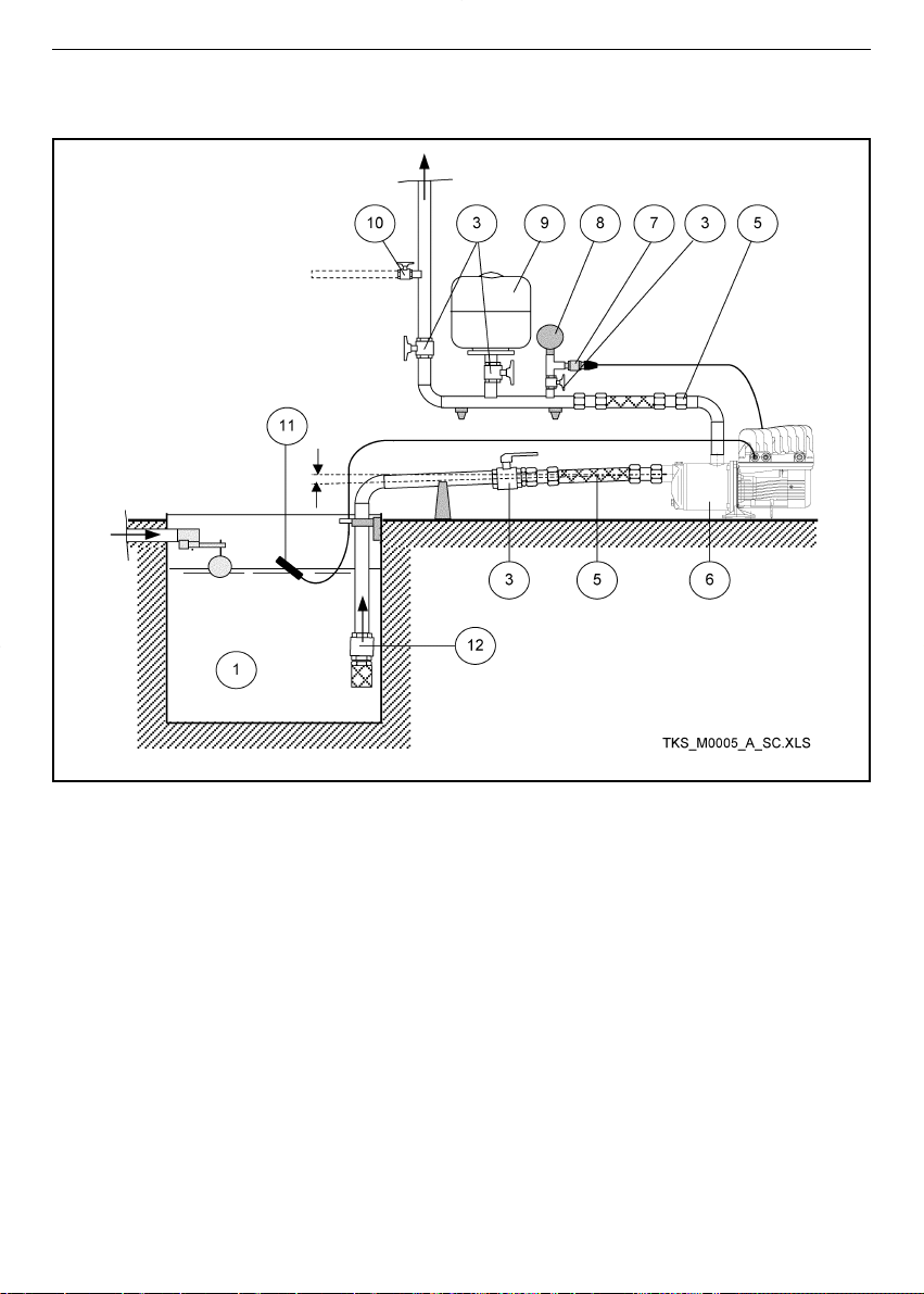
98
1 Vasca
3 Valvola di intercettazione
5 Tubo flessibile
6 Elettropompa con Teknospeed
7 Trasmettitore di pressione
8 Manometro
9 Autoclave a membrana
10 Rubinetto di prova
11 Galleggiante
12 Valvola di fondo
1 Tank
3 On-off valve
5 Flexible pipe
6 Electric pump with Teknospeed
7 Pressure transmitter
8 Pressure gauge
9 Diaphragm tank
10 Test tap
11 Float switch
12 Foot valve
1 Cuve
3 Vanne d’arrêt
5 Tuyau flexible
6 Électropompe avec Teknospeed
7 Capteur de pression
8 Manomètre
9 Surpresseur à membrane
10 Robinet d’essai
11 Flotteur
12 Clapet de pied
Soprabattente - Suction lift - Aspiration au-dessus du niveau de l’eau
Obere Saugleitung - Bomba sobre el nivel del líquido que se debe aspirar
Altura de aspiração - Boven de aanzuighoogte
it en fr de es pt nl

99
1 Wanne
3 Sperrventil
5 Biegsames Rohr
6 Motorpumpe mit Teknospeed
7 Druckübertragungsgerät
8 Manometer
9 Membrandruckbehälter
10 Testhahn
11 Schwimmerschalter
12 Bodenventil
1 Tanque
3Válvula de intercepção
5 Tubo flexível
6 Electrobomba com Teknospeed
7 Transmissor de pressão
8 Manómetro
9 Autoclave de membrana
10 Torneira de prova
11 Flutuador
12 Válvula de pé
1 Tanque
3Válvula de cierre
5 Tubo flexible
6 Electrobomba con Teknospeed
7 Transmisor de presión
8 Manómetro
9 Acumulador hidráulico de membrana
10 Grifo de prueba
11 Interruptor de flotador
12 Válvula de pie
1 Bak
3 Afsluiter
5 Flexibele slang
6 Elektropomp met Teknospeed
7 Druktransmitter
8 Manometer
9 Membraantank
10 Testkraan
11 Vlotterschakelaar
12 Bodemklep
Valvola di non ritorno - Non return valve - Clapet antiretour - Rückschlagventil
Válvula de retención - Válvula anti-retorno - Balkeerklep
it en fr de es pt nl

100
Adesivo (capitolo 6) - Adhesive plate (chapter 6) - Autocollant (chapitre 6) - Klebeetikette (Kapitel 6)
Adhesivo (capítulo 6) - Placa adesiva (capítulo 6) - Sticker (hoofdstuk 6)
1 Spia di segnalazione presenza tensione
2 Spia di segnalazione pompa in marcia
3 Spia di segnalazione anomalia
4 Avvertenze
1 Luz indicadora de presencia tensión
2 Luz indicadora de bomba en marcha
3 Luz indicadora de anomalía
4 Advertencias
1 Power on indicator light
2 Pump running indicator light
3 Malfunction indicator light
4 Warnings
1 Luz de aviso presença tensão
2 Luz de aviso bomba em funcionamento
3 Luz de aviso anomalia
4 Advertências
1 Voyant de signalisation présence tension
2 Voyant de signalisation pompe en marche
3 Voyant de signalisation anomalie
4 Avertissements
1 Waarschuwingslampje stroom
ingeschakeld
2 Waarschuwingslampje pomp in werking
3 Waarschuwingslampje storing
4 Waarschuwingen
1 Kontrollleuchte Spannung vorhanden
2 Kontrollleuchte Pumpe in Gang
3 Kontrollleuchte Anomalien
4 Hinweise
it en fr de es pt nl
 Loading...