

Page 1
Instrucciones para la instalación y el
MANUALE PROGRAMMAZIONE
it
GRUPPI PRESSIONE VELOCITA’ FISSA
FIXED SPEED BOOSTER SETS
en
PROGRAMMING MANUAL
MANUEL DE PROGRAMMATION
fr
GROUPES DE SUPRESSION à VITESSE FIXE
PROGRAMMIERHANDBUCH FÜR
DRUCKANLAGEN MIT FIXER
de
GESCHWINDIGKEIT
MANUAL DE PROGRAMAÇÃO DAS
UNIDADES DE PRESSURIZAÇÃO DE
pt
VELOCIDADE FIXA
MANUAL DE PROGRAMACIÓN GRUPOS DE
es
PRESIÓN DE VELOCIDAD FIJA
Istruzioni d’installazione e uso
Installation and Operating
Instructions
Directives d’utilisation
Installations- und
Bedienungsanleitungen
Instruções para a instalação e a
utilização
uso
Conservate con cura il manuale per future consultazioni
it
Keep this manual for future reference
en
Conservez ce Manuel pour référence
fr
Das Handbuch sorgfältig für zukünftige Konsultationen aufbewahren
de
Conservar cuidadosamente o manual para consultas futuras
pt
Guardar con cuidado el manual para poderlo consultar en el futuro
es
cod. 001073624 rev. D ed. 03/2012
Page 2

2
Page 3

SM30
BSETF3
ITALIANO INDICE ISTRUZIONI .....................................................................................4
ENGLISH INSTRUCTIONS - CONTENTS........................................................................30
FRANÇAIS SOMMAIRE DES DIRECTIVES…………………………………………………….. 56
DEUTSCH INHALT DER ANLEITUNGEN.........................................................................83
PORTUGUÊS ÍNDICE INSTRUÇÕES ...................................................................................111
ESPAÑOL ÍNDICE INSTRUCCIONES..............................................................................138
3
Page 4
it
ATTENZIONE
PERICOLO
it
it it
AVVERTIMENTI PER LA SICUREZZA DELLE PERSONE E DELLE COSE
AVVERTIMENTI PER LA SICUREZZA DELLE PERSONE E DELLE COSE
AVVERTIMENTI PER LA SICUREZZA DELLE PERSONE E DELLE COSEAVVERTIMENTI PER LA SICUREZZA DELLE PERSONE E DELLE COSE
Di seguito i simboli utilizzati
ITALIANO INDICE ISTRUZIONI
ITALIANO INDICE ISTRUZIONI
ITALIANO INDICE ISTRUZIONI ITALIANO INDICE ISTRUZIONI
Rischio di dani alle persone, e alle cose se non osservate quanto
prescritto
SCOSSE ELETTRICHE
Rischio di scosse elettriche se non osservate quanto prescritto
AVVERTENZA
Rischio di danni alle cose o all'ambiente se non osservate quanto
prescritto.
1 GENERALITÀ 5
2 DESCRIZIONE DEL PRODOTTO 5
3 FUNZIONAMENTO 5
4 INSTALLAZIONE 7
5 IMPOSTAZIONI GENERALI 10
6 PROGRAMMAZIONE 11
7 ALLARMI 24
8 STRUTTURA PARAMETRI 26
9 BUS DI CAMPO MODBUS 26
10 MANUTENZIONE DELLA SCHEDA ELETTRONICA 28
11 RIPARAZIONI- RICAMBI 28
12 RICERCA GUASTI 28
13 DISMISSIONE 29
Questo manuale si compone di due parti, la prima destinata all'installatore e all'utilizzatore, la seconda
solo per l'installatore.
4
Prima d'iniziare l'installazione leggere attentamente queste istruzioni e attenersi alle normative
locali.
L'installazione e la manutenzione devono esseguite da personale qualificato.
Il gruppo di pressione è una macchina automatica, le pompe possono avviarsi in modo
automatico senza preavviso.Il gruppo contiene acqua in pressione, ridurre a zero la pressione
prima d'intervenire.
Eseguire i collegamenti elettrici nel rispetto delle normative.
Assicurare un efficiente impianto di terra.
Prima di ogni intervento sul gruppo scollegare l'alimentazione elettrica
In caso di danneggiamento del gruppo scollegare l'alimentazione elettrica per evitare scosse
elettriche.
Page 5

Il pro
gramma memorizzato (Software) aziona le pompe
ATTE
ATTEATTE
ATTE
NZIONE
NZIONENZIONE
NZIONE
1111
2222
3333
4444
1 GENERALITÀ
1 GENERALITÀ
1 GENERALITÀ1 GENERALITÀ
I gruppi di pressione Lowara serie GSD, GSY sono progettati per trasferire e aumentare la pressione
dell'acqua pulita negli impianti idrici di abitazioni, uffici, comunità e industria.
Questo manuale descrive la programmazione della scheda elettronica di controllo in seguito denominata
SM30 BSETF3, per le istruzioni d’uso e manutenzione del gruppo fare riferimento al relativo manuale.
Caratteristiche
Caratteristiche e
Caratteristiche Caratteristiche
e Limiti d'impiego
Limiti d'impiego
e e
Limiti d'impiegoLimiti d'impiego
Tensione nominale di impiego scheda SM30
24 Vac/Vdc +/- 15%
BSETF3:
Assorbimento: 4 VA max (circa 0,5 VA in stand-by)
Temperatura ambiente utilizzo e stoccaggio: -10 °C + 65 °C
Umidità relativa: 30% a 90 °C MAX, senza condensazione
Ambiente: Interno
Grado di protezione IP del frontale: IP65
Ambienti polverosi, con presenza di sabbia o ambienti umidi di tipo marino possono provocare
deterioramenti precoci compromettendo il regolare funzionamento.
CONTROLLO DEL MATERIALE
CONTROLLO DEL MATERIALE
CONTROLLO DEL MATERIALECONTROLLO DEL MATERIALE
Al ricevimento del gruppo controllare che il materiale ricevuto corrisponda a quanto indicato nei
documenti di trasporto che accompagnano il gruppo stesso.
CONSERVARE CON CURA TUTTA LA DOCUMENTAZIONE FORNITA.
CONSERVARE CON CURA TUTTA LA DOCUMENTAZIONE FORNITA.
CONSERVARE CON CURA TUTTA LA DOCUMENTAZIONE FORNITA.CONSERVARE CON CURA TUTTA LA DOCUMENTAZIONE FORNITA.
LA DOCUMENTAZIONE CARTACEA TEME L’UMIDITÁ!
LA DOCUMENTAZIONE CARTACEA TEME L’UMIDITÁ!
LA DOCUMENTAZIONE CARTACEA TEME L’UMIDITÁ!LA DOCUMENTAZIONE CARTACEA TEME L’UMIDITÁ!
2 DES
2 DESCRIZIONE DEL PRODOTTO
CRIZIONE DEL PRODOTTO
2 DES2 DES
CRIZIONE DEL PRODOTTOCRIZIONE DEL PRODOTTO
Scheda elettronica di controllo dotata di visualizzatore LCD, led di segnalazione e pulsanti di comando,
inserita nel quadro elettrico del gruppo di pressione.
3 FUNZIONAMENTO
3 FUNZIONAMENTO
3 FUNZIONAMENTO3 FUNZIONAMENTO
SM30_a_001
tramite il quadro elettrico in base alla richiesta
dell'impianto.
Il display LCD fornisce indicazioni sullo stato di
funzionamento del sistema, insieme alle segnalazioni
led:
1) LINEA: Led verde, presenza tensione di alimentazione;
2) ANOMALIA: Led rosso, indicatore d’anomalia;
3) BASSO LIVELLO: Led rosso, presenza allarme bassa
pressione/livello in aspirazione;
4) P
: Led verde, pompa in funzione;
1
….
P3 in funzione.
Il numero di pompe dipende da quelle presenti nel
gruppo.
it
it
it it
5
Page 6
it
it
it it
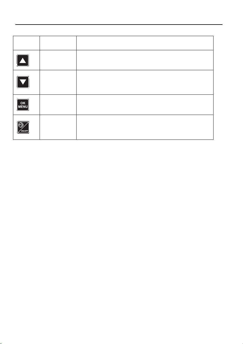
Simbolo Nome Descrizione
↑UP/SU
↓DOWN /GIU’
OK/MENU’
P1, P2, P3
Modo Manuale
Modo Manuale
Modo ManualeModo Manuale
Nel modo Manuale le pompe possono essere avviate e fermate con i tasti P1/ON-OFF, P2/ON-OFF, P3/ONOFF e non c’è alcuna regolazione della pressione.
I controlli di bulbo fuori curva, allarme di minimo livello, allarme soglia massima pressione, allarme soglia
minima pressione, allarme blocco da esterno, sono disattivati.
Modo Automatico
Modo Automatico
Modo AutomaticoModo Automatico
Nel modo automatico le pompe sono comandate dalla scheda SM30 BSETF3 secondo la richiesta
proveniente dal sensore di pressione o dal consenso dei pressostati, per mantenere la pressione al valore
desiderato.
Per funzionare correttamente la scheda deve essere programmata con i parametri dell’impianto.
Ogni volta che si accende la scheda, il funzionamento di defult è automatico.
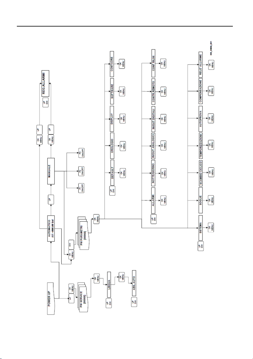
Programmazione
Programmazione
ProgrammazioneProgrammazione
La programmazione della scheda si effettua modificando i parametri presenti in due menù chiamati
Menù parametri e Menù di servizio.
Un terzo menù permette di visualizzare gli allarmi intervenuti. Il menù Storico allarmi è accessibile sia in
modo automatico che in modo manuale.
Menù parametri
Menù parametri
Menù parametriMenù parametri
La scheda elettronica SM30 BSETF3 è fornita già programmata, tuttavia potrebbe essere necessario
modificare alcuni parametri per un funzionamento migliore. Il menù di programmazione Parametri
contiene i parametri del sistema (numero di pompe, presenza pompa pilota, scelta tra sistema con
sensore di pressione e sistema a pressostati, default, elenco completo ved. capitolo 6).
Menù di servizio
Menù di servizio
Menù di servizioMenù di servizio
All’interno del menù è possibile cambiare lingua, abilitare il cambio dei seguenti parametri in
funzionamento automatico: soglie di lavoro START/STOP elettropompe, sensibilità sonde,
temporizzazioni, compensazioni perdite.
Commuta tra il modo Automatico e quello Manuale
Scorrimento in avanti delle finestre
Incremento di un valore durante "modifica dato"
Scorrimento indietro delle finestre
Decremento di un valore durante "modifica dato"
Conferma menù
Conferma dato inserito
Modalità manuale, avviamento (ON) e fermata (OFF) pompa “n”.
Tasto P3 ha anche la funzione di (ESC) e di riconoscimento/
spegnimento del led ANOMALIA
6
Page 7
INFORMAZIONI PER L'INSTALLATORE
ATTENZIONE
4 INSTALLAZIONE
4 INSTALLAZIONE
4 INSTALLAZIONE4 INSTALLAZIONE
La scheda è fornita già collegata nel quadro e programmata, se necessario modificare le impostazioni
vedere il capitolo Impostazioni. Per i collegamenti fare riferimento allo schema del quadro elettrico.
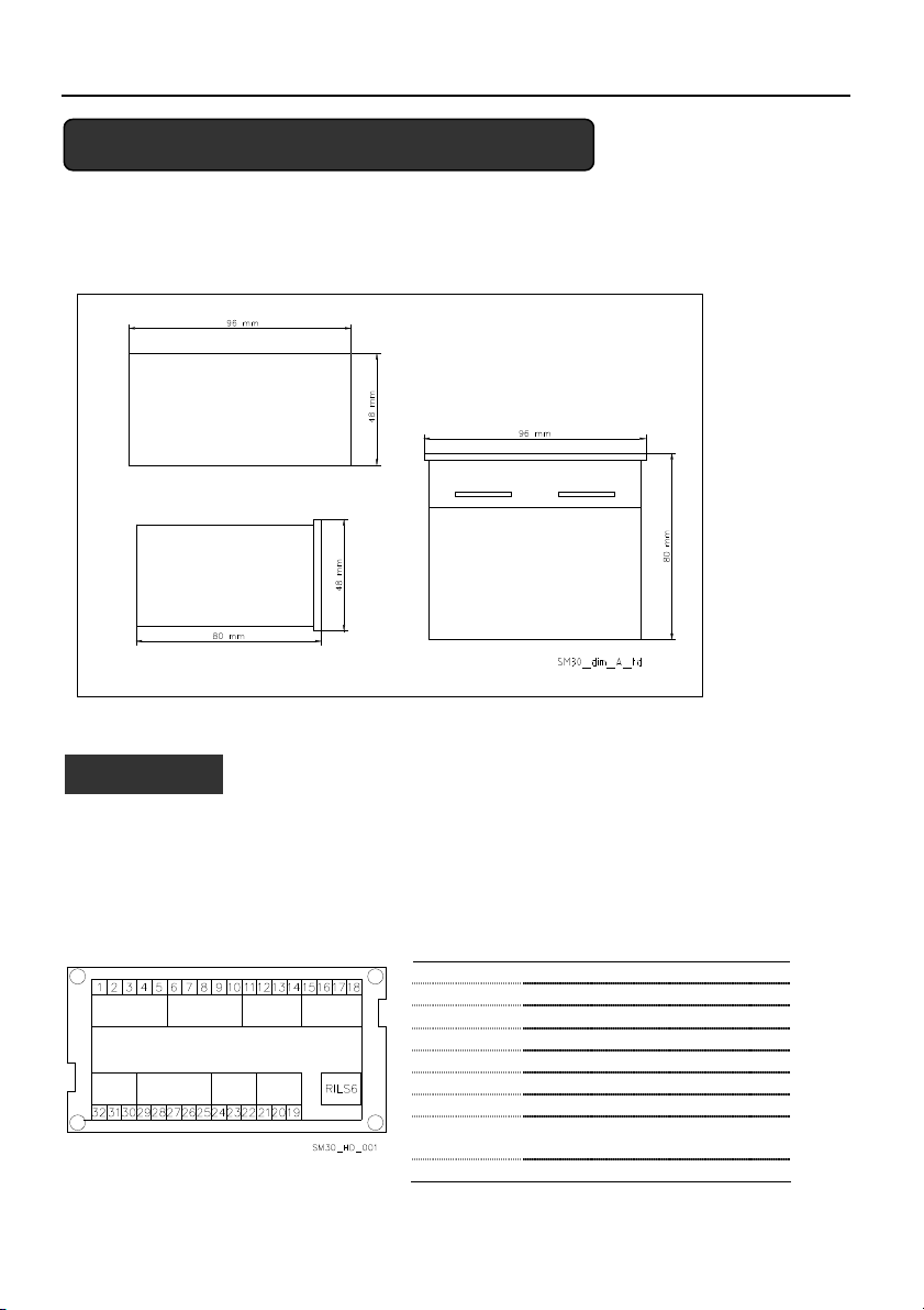
4.1 Panoramica term
4.1 Panoramica terminali
4.1 Panoramica term4.1 Panoramica term
A B
H
G
Non avviare le pompe prima di averle riempite di liquido. Vedere il manuale
d'istruzione delle pompe.
Dettagli collegamenti, vedi schema quadro elettrico
inali
inaliinali
Gruppo A Ingressi digitali optoisolati
D
C
EF
Gruppo B Ingressi digitali optoisolati
Gruppo C Relè allarme
Gruppo D Comando relé pompe
Gruppo E Comunicazione Bus RS485
Gruppo F Controllo Livello
Gruppo G Ingressi/Uscita analogiche
Gruppo H Alimentazione +24 Vac/dc +/-
RILS 6 Collegamento scheda RILS6
15%
it
it
it it
7
Page 8

it
it
it it
4444.1.
.1.1111 Gruppo A,
Gruppo A, B
.1..1.
Gruppo A,Gruppo A,
N° Sigla Descrizione
1 COM Terminale comune per ingressi digitali ON/OFF
2 PR1 Pressostato comando pompa 1
3 PR2 Pressostato comando pompa 2
4 PR3 Pressostato comando pompa 3
5 TERM1 Protezione termica / PTC pompa 1
6 TERM2 Protezione termica / PTC pompa 2
7 TERM3 Protezione termica / PTC pompa 3
8 AUX1 Contatto ausiliario 1, configurabile come pressostato di max pressione o
9 AUX2 Contatto ausiliario 2, configurabile come consenso da esterno (NO) o allarme
10 AUX3 Contatto ausiliario 3, configurabile come cambio set (contatto NO) o
Caratterist
Caratteristiche:
CaratteristCaratterist
4.1.
4.1.2222 Gruppo C
Gruppo C, uscita relè e
4.1.4.1.
Gruppo C Gruppo C
N° Sigla Descrizione
11 NO Uscita Contatto Relè Allarme / Elettrovalvola, 30 Vac max 1 A
12 COM Uscita Comune Relè Allarme / Elettrovalvola
13 +12Vdc Uscita allarme+12 Vdc, 50 mA
14 GND Uscita allarme+12 Vdc, ground
4.1.
4.1.3333 Gruppo D, comando relè pompe
Gruppo D, comando relè pompe
4.1.4.1.
Gruppo D, comando relè pompe Gruppo D, comando relè pompe
B ingressi digitali
ingressi digitali,,,, optoisolati
B B
ingressi digitaliingressi digitali
comando autoprova da esterno.
da esterno (NC).
interruttore di Bulbo Fuori Curva (B.F.C.)
iche: Soglia OFF= corrente con ingresso chiuso = 4mA
iche:iche:
, uscita relè e uscita
, uscita relè e , uscita relè e
optoisolati
optoisolati optoisolati
uscita+12Vdc
+12Vdc
uscitauscita
+12Vdc +12Vdc
N° Sigla Descrizione
15 P1 Uscita relé comando contattore pompa 1
16 P2 Uscita relé comando contattore pompa 2
17 P3 Uscita relé comando contattore pompa 3
18 COM Comune uscita circuito comando pompe
Caratteristiche
Caratteristiche del contatto
CaratteristicheCaratteristiche
4.1.
4.1.4444 Gruppo E,
Gruppo E, Interfaccia utente
4.1.4.1.
Gruppo E, Gruppo E,
N° Sigla Descrizione
19
20
21
8
del contatto:::: 30 Vac max 1A
del contatto del contatto
Interfaccia utente RS485
Interfaccia utente Interfaccia utente
A RS485
B RS485
GND
Com. Bus di campo
Com. Bus di campo
Massa
RS485
RS485RS485
Page 9

4.1.
4.1.5555 Gruppo F, controllo livello
Gruppo F, controllo livello
4.1.4.1.
Gruppo F, controllo livello Gruppo F, controllo livello
N° Sigla Descrizione
22 HIGH Ingresso sonda alto livello / galleggiante / pressostato di minima
23 LOW Ingresso sonda basso livello
24 COM Comune circuito sonde / galleggiante / pressostato di minima
Caratteristiche:
Caratteristiche:
Caratteristiche:Caratteristiche:
Tensione alimentazione 3.6Vp-p.
4.1.
4.1.6666 Gruppo G, Ingressi/uscite analogiche
Gruppo G, Ingressi/uscite analogiche
4.1.4.1.
Gruppo G, Ingressi/uscite analogiche Gruppo G, Ingressi/uscite analogiche
N° Sigla Descrizione
25 GND_A Rif. Elettronico collegamento schermo cavo sensore
26 Out_A Uscita segnale analogico
27 AI1 Ingresso valore attivo sensore 1
28 AI2 Ingresso valore attivo sensore 2
29 PWR_A Alimentazione sensore +13.5 Vdc
Caratteristiche:
Caratteristiche:
Caratteristiche:Caratteristiche:
Tensione 0-11 V, accuratezza 0,3%;
Ingresso corrente 0-22 mA, accuratezza 0,3%, protezione contro il cortocicuito.
Tensioni massime in ingresso = 30 Vdc.
4.1.7 Gruppo H, Alim
4.1.7 Gruppo H, Alimentazione
4.1.7 Gruppo H, Alim4.1.7 Gruppo H, Alim
N° Sigla Descrizione
30 PE Collegamento di terra
31 0Vac Alimentazione scheda
32 24Vac Alimentazione scheda
CCCCaratteristiche:
aratteristiche:
aratteristiche:aratteristiche:
Tensione 24Vac +/-10%
Frequenza 50/60Hz
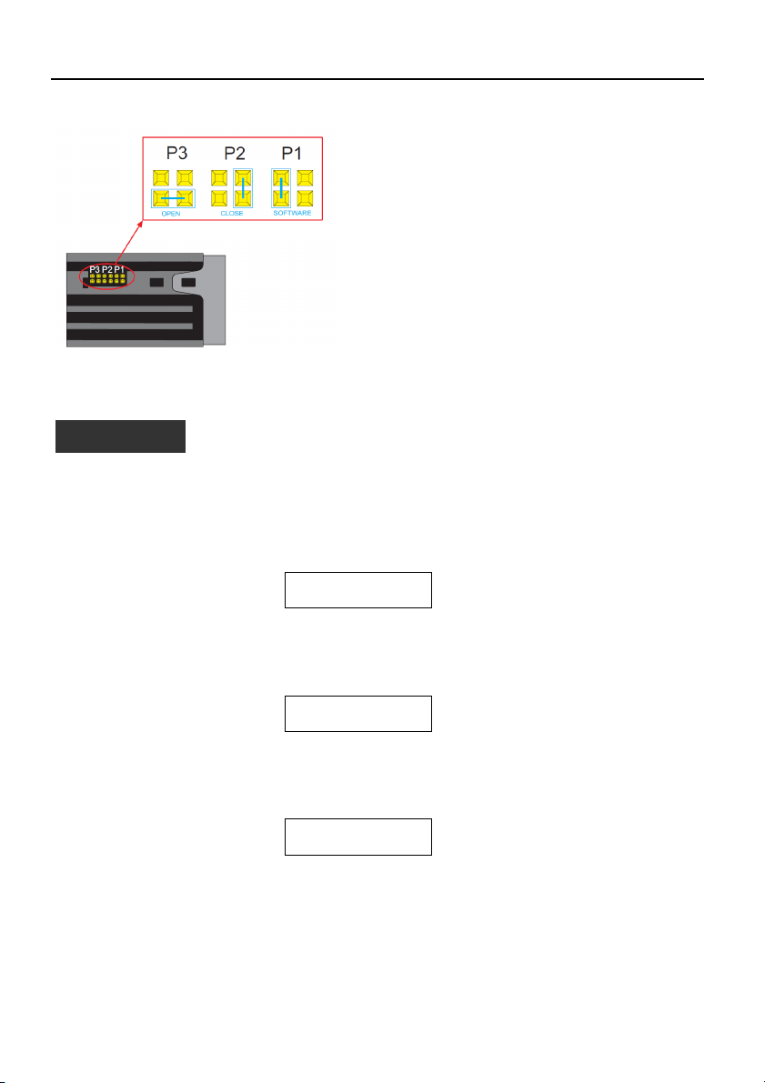
4.2 Panoramica
4.2 Panoramica jumpers
4.2 Panoramica 4.2 Panoramica
I jumpers di by pass eseguono un by pass sull’elettronica attivando direttamente i contattori di comando
elettropompe senza alcun controllo di regolazione.
Si usano in caso di emergenza, quando la scheda elettronica è fuori uso ed è necessario garantire il
funzionamento delle elettropompe.
Posizione OPEN = I contattori delle elettropompe sono disattivati.
Posizione CLOSE = I contattori delle elettropompe vengono permanentemente attivati e non viene
eseguito nessun controllo di regolazione (da utilizzare solo in situazioni di emergenza).
Posizione SOFTWARE = controllo dei contattori delle elettropompe da scheda elettronica;
La posizione di default dei Jumpers è SOFTWARE.
entazione
entazioneentazione
jumpers di by pass
di by pass
jumpersjumpers
di by pass di by pass
it
it
it it
9
Page 10
it
ATTENZIONE
it
it it
5 IMPOSTAZIONI GENERALI
5 IMPOSTAZIONI GENERALI
5 IMPOSTAZIONI GENERALI 5 IMPOSTAZIONI GENERALI
5.1 Mod
5.1 Modo automatico / manuale
o automatico / manuale
5.1 Mod5.1 Mod
o automatico / manuale o automatico / manuale
All’ accensione la scheda elettronica si dispone in modo automatico.
Nel caso di sistema con sensore di pressione appare la finestra:
AUTOMATICO
##.## è il valore di pressione attuale.
Nel caso di sistema a pressostati appare invece la finestra:
AUT: PRESSOSTATI
E’ possibile passare da modo AUTOMATICO a MANUALE, e viceversa, premendo il pulsante ↑UP.
Nel modo MANUALE e AUTOMATICO si può visualizzare il Registro Allarmi premendo
contemporaneamente i pulsanti ↑UP e OK/MENU’. E’ visualizzata la seguente finestra
REGISTRO
Dal modo AUTOMATICO (se abilitato nel Menù Sistema) o MANUALE si accede al menù impostazione
parametri premendo contemporaneamente i pulsanti ↓DOWN e OK/MENU’.
5.
5.2 Regole generali di modifica e inserimento dati
2 Regole generali di modifica e inserimento dati
5.5.
2 Regole generali di modifica e inserimento dati2 Regole generali di modifica e inserimento dati
All’interno di un menù utilizzare i pulsanti ↑UP e ↓DOWN per passare da una finestra all’altra. Ogni
finestra si riferisce ad un singolo parametro da impostare oppure ad un submenù.
Per ogni finestra è proposto un valore di default che può essere modificato secondo le proprie esigenze.
10
Le regolazioni possono influire sul corretto funzionamento del gruppo.
AI1 + ###.## bar
------------
ALLARMI
Page 11

ATTENZIONE
Per modificare un parametro o accedere ad un submenù, all’interno di una finestra, premere tasto
OK/MENU’.
Il parametro in modifica appare tra due parentesi quadre [ ] se facente parte di una lista, mentre per i
valori numerici un cursore lampeggiante indica la cifra in editazione; in entrambe i casi, usare i pulsanti
↑UP e ↓DOWN per modificare il valore.
Se un parametro è un numero a più cifre queste sono modificate separatamente, per passare alla cifra
successiva premere OK/MENU’.
Ottenuto il valore desiderato premere OK/MENU’per confermare il valore oppure premere il tasto P3 (ESC)
per annullare.
Per uscire da un menù o un submenù premere il tasto P3 (ESC) oppure premere ripetutamente il tasto
↑UP o il tasto ↓DOWN fino al messaggio ESCI, selezionare SI e confermare con OK/MENU .
Valori di Default.
Valori di Default.
Valori di Default.Valori di Default.
I valori di Default sono quelli di fabbrica e sono ripristinabili dal menù DEFAULT.
6 PROGRAMMAZIONE
6 PROGRAMMAZIONE
6 PROGRAMMAZIONE 6 PROGRAMMAZIONE
6.1 Menù service
6.1 Menù service
6.1 Menù service 6.1 Menù service
Le modifiche sul menù di servizio devono essere effettuate da personale qualificato.
All’accensione della scheda premere i tasti OK/MENU’ e ↑UP fino a quando compare sul display il
messaggio:
PASSWORD SERVICE
Impostare la password 00066 con i tasti ↑UP e ↓DOWN e confermare con OK/MENU’per entare nel menù
service.
Se la password è errata viene proposto il menù in sola lettura ed appare la seguente finestra
PASSWORD ERRATA
Display Commento Campo Default
LINGUA Impostazione della lingua.
ABIL AUTO Abilitazione a modificare alcuni parametri in
Le regolazioni possono influire sul corretto funzionamento del gruppo.
[00066]
SOLA LETTURA
Alcuni linguaggi potrebbero non essere attivi,
in tal caso sono automaticamente visualizzate
le scritte in italiano.
funzionamento AUTOMATICO.
ITALIANO,
ENGLISH,
FRANÇAIS,
DEUTSCH,
PORTUGUÊS,
ESPANÕL
SI
NO
ITALIANO
NO
11
it
it
it it
Page 12

it
Tipo di
sensore utilizzato:
Pressostati
S
ENS.PRESSIONE
it
it it
6.2 Menù parametri
6.2 Menù parametri
6.2 Menù parametri6.2 Menù parametri
I parametri di configurazione e di controllo della macchina vengono inseriti da tastiera durante le
operazioni di taratura e di collaudo effettuate in fabbrica, ma possono essere modificati in seguito.
Poiché il gruppo non può essere utilizzato durante le operazioni d’inserimento dei parametri è necessario
chiudere la valvola d’intercettazione posta sul collettore di mandata, oppure tutte le utenze.
Accendere il quadro elettrico, il sistema si dispone, di default, in automatico. E’ possibile passare da
modo AUTOMATICO a MANUALE, e viceversa, premendo il pulsante ↑UP.
A display compare, nel caso di sistema con sensore di pressione:
AUTOMATICO
AI1 + ###.## bar
##.## è il valore di pressione attuale.
Nel caso di sistema a pressostati appare invece la finestra:
AUT: PRESSOSTATI
-----------
Premere i tasti ↓DOWN e OK/MENU’ fino a quando compare sul display il messaggio:
PASSWORD PARAM.
[00066]
Impostare la password 00066 con i tasti ↑UP e ↓DOWN e confermare con OK/MENU’per entare nel menù
parametri.
Se la password è errata viene proposto il menù in sola lettura ed appare la seguente finestra
PASSWORD ERRATA
SOLA LETTURA
6.2.1 SISTEMA
6.2.1 SISTEMA
6.2.1 SISTEMA6.2.1 SISTEMA
Fase Display Commento Campo Default
0000
SISTEMA
SISTEMA
SISTEMASISTEMA
1 NUMERO POMPE Nr totale di pompe inclusa
eventuale pilota.
1
3
2
3
2 POMPA PILOTA Indicare la presenza pompa pilota SI
NO
NO
3 COMANDO DA
Sensore di pressione
Sensore temperatura
Sensore portata
Sensore livello
SENS.TEMPERAT.
SENS.PORTATA
SENS. LIVELLO
PRESSOSTATI
SENS.
PRESSIONE
12
Page 13

4 F.SCALA SENSORE Fondo scala sensore: è definito dal
5 CONTR. LIVELLO Dispositivo utilizzato per il controllo
6 SENSIB. SONDE Regolazione della sensibilità delle
7 RETROAZIONE Impostazione del segnale analogico
Regolazione sensibilità sonde
Regolazione sensibilità sonde
Regolazione sensibilità sondeRegolazione sensibilità sonde
La regolazione è ottenuta impostando il valore di sensibilità. Per una nuova regolazione procedere nel
seguente modo:
Verificare che il livello dell’acqua copra le sonde.
Assicurarsi che il ritardo RIT. BASSO LIV. sia impostato a zero.
Variare leggermente il valore di sensibilità sino a quando si accende il led rosso “BASSO LIVELLO” e
compare il messaggio relativo di allarme.
Aumentare leggermente il valore numerico della sensibilità fino a che si spegne il led rosso “BASSO
LIVELLO”.
tipo di sensore scelto.
Pressione
0-10 bar
0-16 bar
0-25 bar
0-50 bar
Livello
Ultrasuoni: 0-15 m
Piezometrico: 0-10 m
Temperatura
-200 + 850 °C
Portata
DN80 3.62-181 mc/h
DN100 5.65-283 mc/h
DN125 8.84-442 mc/h
DN150 12.7-637 mc/h
DN200 22.6-1131 mc/h
DN250 35.3-1727 mc/h
basso livello/bassa pressione
tramite
sonde/galleggiante/pressostato di
minima collegati ai morsetti
dedicati HIGH (22), LOW(23) e
COM(24).
sonde in funzione della
conducibilità dell’acqua.
usato come retroazione del sistema.
Se selezionato AI1 or AI2, in caso di
guasto di un sensore,
automaticamente la retroazione è
eseguita dal sensore alternativo
0-10 bar
0-16 bar
0-25 bar
0-50 bar
Ultras 0-15 m
Piezo 0-10 m
NESSUNA
PRESS./GALL.
TRE SONDE
5-100 kOhm 50 kOhm
AI1
AI2
AI1/AI2
0-10.00 bar
PRESS./GALL
AI1/AI2
13
it
it
it it
Page 14

it
it
it it
6.2.2 SOGLIE A
6.2.2 SOGLIE AVVIO/STOP
6.2.2 SOGLIE A6.2.2 SOGLIE A
Nota: I parametri SOGLIE sono impostabili solo con sistema a sensore di pressione o di livello.
Le soglie devono essere impostate in considerazione delle prestazioni idrauliche della pompa (cuva Q-H) e
del tipo di impianto.
Fase Display Commento Campo Default
0000
1 SOGLIA STOP P1
2 SOGLIA START P1
3 SOGLIA STOP P2
4 SOGLIA START P2
5 SOGLIA STOP P3
6 SOGLIA START P3
6.2.3 SCAMBIO CICLICO
6.2.3 SCAMBIO CICLICO AVVIO POMPE
6.2.3 SCAMBIO CICLICO 6.2.3 SCAMBIO CICLICO
Fase Display Commento Campo Default
0000
1 SCAMBIO CICLICO Abilitazione dello scambio ciclico.
2 PRIMA P.START Inserire la pompa di servizio che si desidera
3 TEMPO SCAMBIO Nel caso non avvenga uno scambio ciclico in
NOTA : Se presente, la pompa pilota non viene interessata dallo scambio ciclico e viene avviata per prima,
rimane accesa all’avvio delle pompe di servizio e spenta per ultima.
14
VVIO/STOP DELLE POMPE
VVIO/STOP VVIO/STOP
SOGLIE
SOGLIE Applicazione con pressione / livello
SOGLIESOGLIE
SCAMBIO CICLICO
SCAMBIO CICLICO
SCAMBIO CICLICOSCAMBIO CICLICO
DELLE POMPE
DELLE POMPEDELLE POMPE
Applicazione con pressione / livello
Applicazione con pressione / livelloApplicazione con pressione / livello
Soglia (pressione/livello) di stop (OFF) per
la pompa 1
Soglia (pressione/livello) di avvio (ON)
per la pompa 1
Soglia (pressione/livello) di stop (OFF) per
la pompa 2
Soglia (pressione/livello di avvio (ON) per
la pompa 2
Soglia (pressione/livello) di stop (OFF) per
la pompa 3
Soglia (pressione/livello) di avvio (ON)
per la pompa 3
AVVIO POMPE
AVVIO POMPEAVVIO POMPE
Impostare SI per attivare lo scambio ciclico delle
pompe. Lo scambio ciclico automatico avviene
ad ogni riavvio del gruppo dopo una fermata in
automatico.
La pompa pilota se presente non è soggetta
allo scambio ciclico e quindi si avvia sempre per
prima.
parta come prima dopo un’accensione elettrica
del gruppo.
Nei sistemi con pilota, essendo quest’ultima
denominata P1, la prima pompa di servizio
impostabile può essere esclusivamente P2 o P3.
automatico (gruppo non ha mai avuto modo di
fermarsi) dopo il tempo impostato viene
effettuato uno scambio ciclico “forzato” delle
pompe di servizio (esclusa pilota).
Per disabilitare tale funzione impostare 0h
0.. FS +3.50 bar
0.. FS +2.70 bar
0.. FS +3.40 bar
0.. FS +2.60 bar
0.. FS +3.30 bar
0.. FS +2.50 bar
SI
NO
P1
P2
P3
0 h
1÷12 h
SI
P1
0 h
Page 15

6.2.4
6.2.4 TEMPORIZZAZIONI
TEMPORIZZAZIONI
6.2.4 6.2.4
TEMPORIZZAZIONITEMPORIZZAZIONI
Le temporizzazioni sono attive sia con sistema a pressotati che con sistema a sensori.
Fase Display Commento Campo Default
0000
TEMPORIZZAZIONI
TEMPORIZZAZIONI
TEMPORIZZAZIONITEMPORIZZAZIONI
1 RIT. START P1
2 RIT. START P2-P3
3 RIT. STOP P1 Tempo di ritardo arresto P1 (pilota
4 RIT. STOP P2- P3
5 TEMPI RIDOTTI Impostabile solo se sistema a sensore.
6.2.5 AUT
6.2.5 AUTOPROVA PERIODICA
6.2.5 AUT6.2.5 AUT
Nei sistemi soggetti a lunghi periodi d’inattività è consigliato un test automatico periodico (autoprova) di
funzionamento con lo scopo di verificare le prestazioni del gruppo.
In ogni caso l’autoprova non può sostituire una manutenzione programmata che deve essere
periodicamente eseguita. Consigliata una cadenza tipo settimanale.
Per avviare la richiesta di test si può utilizzare l’orologio interno scheda oppure un comando da esterno.
Quando l’autoprova viene abilitata, il relè di allarme è automaticamente configurato per il comando
dell’elettrovalvola.
E’ inoltre necessario assicurarsi che il parametro CONFIG. IN. AUX3 nel MENU’ IN/OUT DIGITALI sia
impostato come B.F.C.
Fase Display Commento Campo Default
1 COMANDO AUTOP. Sorgente comando autoprova.
OPROVA PERIODICA
OPROVA PERIODICAOPROVA PERIODICA
0000
AUTOPROVA
AUTOPROVA
AUTOPROVAAUTOPROVA
Ritardo sull’avviamento P1 (pilota
inclusa). Il conteggio della
temporizzazione inizia dalla richiesta di
avvio da parte del pressostato/sensore
Tempo di ritardo avvio P2 - P3. Il
conteggio del tempo inizia dalla
richiesta di avvio da parte del
pressostato/sensore
inclusa).
Il conteggio del tempo inizia dalla
richiesta di spegnimento da parte del
pressostato/sensore.
Tempo di ritardo arresto pompe P2-P3. Il
tempo parte dalla richiesta di
spegnimento da parte del
pressostato/sensore
Dimezzamento dei tempi
precedentemente impostati nel caso di
eccessiva variazione di
pressione/livello/ecc.. del sistema.
Le impostazioni possbili sono:
Disabilitata: l’autoprova è inibita.
Orologio int.: l’autoprova viene attivata
al giorno e ora richiesta tramite orologio
interno alla scheda SM30 BSETF3.
Comando ext: l’autoprova viene attivata
tramite comando esterno collegato
all’ingresso digitale AUX1
0..100 s 3 s
0..100 s 5 s
0..100 s 5 s
0..100 s 3 s
SI
NO
DISABILITATO
OROLOGIO
INT.
COMANDO
EST.
NO
DISABILITATO
15
it
it
it it
Page 16

it
it
it it
2 GIORNO
3 ORA Impostazione ora di esecuzione
4 MINUTI Impostazione minuti di esecuzione
Come avviare l’autoprova
Come avviare l’autoprova
Come avviare l’autoprovaCome avviare l’autoprova
L’autoprova perioca è attivato da:
- un comando esterno, collegato sull’ingresso digitale AUX1
oppure
- l’orologio interno scheda
Se la richiesta arriva durante il funzionamento delle pompe, l’autoprova sarà messo in attesa e compare
ad intervalli regolari la scritta
AUTOMATICO
Appena il gruppo si trova con tutte le pompe spente l’autoprova avrà inizio con il seguente messaggio
AUTOPROVA P1
Durante la pausa tra il test di una pompa e l’altra appare il seguente messaggio:
PAUSA AUTOPROVA
In caso l’autoprova abbia esito negativo apparirà il seguente messaggio:
AUTOMATICO
FFFFasi di esecuzione dell’autoprova
asi di esecuzione dell’autoprova
asi di esecuzione dell’autoprovaasi di esecuzione dell’autoprova
Il test si articola nelle sequenze:
a) Ricevimento comando.
b) Apertura elettrovalvola a bordo gruppo tramite comando del relè ELETTROVALVOLA.
c) Avvio della prima pompa.
d) Chiusura dell’elettrovalvola.
e) Arresto dopo due minuti della pompa in prova.
f) Attesa un minuto.
g) Esecuzione test pompa successiva.
16
Impostazione del giorno di esecuzione
autoprova (parametro attivo solo nel
caso la sorgente di comando è impostata
OROLOGIO INT.)
autoprova (parametro attivo solo nel
caso la sorgente di comando è impostata
OROLOGIO INT.)
autoprova (parametro attivo solo nel
caso la sorgente di comando viene
impostata OROLOGIO INT.)
AUTOP.IN ATTESA
AI1 +###.## bar
AI1 +###.## bar
AUTOP. FALLITA P#
LUN
..DOM
0..24 h 10
0..60 min 00
LUNEDI
Page 17
SUP
INF
1 pompa
2 pompe
3 pompe
Incremento
Soglie variabili per compensazione perdite di carico
Quando l’aut
Quando l’autoprova
Quando l’autQuando l’aut
oprova risulta fallit
risulta fallitaaaa
oprovaoprova
risulta fallit risulta fallit
Se durante l’autoprova (qualsiasi sia la pompa in funzione) interviene il Bulbo Fuori Curva (B.F.C.),
installato a bordo gruppo, l’autoprova viene interrotta definitivamente ed il gruppo ritornerà a funzionare
in modo automatico.
A display compare la scritta AUTOP. FALLITA P#.
L’intervento del B.F.C. è ritardato del tempo impostato sul parametro RIT IN AUX3.
Come interrompere l’autoprova
Come interrompere l’autoprova
Come interrompere l’autoprova Come interrompere l’autoprova
Per interrompere l’autoprova premere il tasto P3 (ESC).
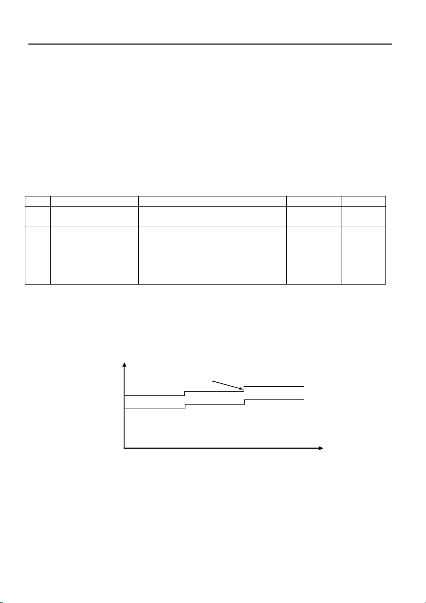
6.2.6
6.2.6 COMPENSAZIONE PERDITE DI CARICO
COMPENSAZIONE PERDITE DI CARICO
6.2.6 6.2.6
COMPENSAZIONE PERDITE DI CARICOCOMPENSAZIONE PERDITE DI CARICO
Talvolta negli impianti si ha un calo di pressione causato dalle perdite di carico distribuite lungo le
tubazioni e crescono all’aumentare della portata d’acqua richiesta.
Fase Display Commento Campo Default
0000 COMPENSAZIONE
COMPENSAZIONE Disponibile solo con sistemi a sensore di
COMPENSAZIONECOMPENSAZIONE
pressione
1 SOGLIA COMP.
Abilitazione compensazione perdite
carico con incremento delle soglie di
000.00 bar 000.00
bar
avvio e di stop in bar per le pompe
successive alla prima.
Impostando pressione = 0 bar la
funzione è disabilitata
Per compensare le perdite di carico dell’impianto è possibile abilitare un controllo che fornisce una
pressione proporzionale al carico. Non viene eseguita la misura diretta del flusso ma si ritiene che sia
proporzionale al numero di pompe accese.
All’accensione di ogni pompa di servizio, oltre la prima, le soglie SUP e INF vengono aumentate del valore
indicato nel parametro SOGLIA COMP.
La pompa pilota è esclusa.
it
it
it it
ON
ON
ON
6.2.7
6.2.7 PROGRAMMAZIONE RELE’ DI ALLARME
PROGRAMMAZIONE RELE’ DI ALLARME
6.2.7 6.2.7
PROGRAMMAZIONE RELE’ DI ALLARMEPROGRAMMAZIONE RELE’ DI ALLARME
La scheda SM30 BSETF3 ha a disposizione un relè d’allarme d’uscita che si attiva nel modo e per il tipo di
allarmi di seguito descritti.
Il relè di allarme è disponibile, e prog
Il relè di allarme è disponibile, e programmabile, solo ed esclusivamente
Il relè di allarme è disponibile, e progIl relè di allarme è disponibile, e prog
è stata abilitata.
è stata abilitata.
è stata abilitata. è stata abilitata.
Se l’AUTOPROVA è abilitata i parametri descritti di seguito non saranno visualizzati.
Se l’AUTOPROVA è abilitata i parametri descritti di seguito non saranno visualizzati.
Se l’AUTOPROVA è abilitata i parametri descritti di seguito non saranno visualizzati.Se l’AUTOPROVA è abilitata i parametri descritti di seguito non saranno visualizzati.
rammabile, solo ed esclusivamente se
rammabile, solo ed esclusivamente rammabile, solo ed esclusivamente
se la
se se
la funzione AUTOPROVA
funzione AUTOPROVA non
lala
funzione AUTOPROVA funzione AUTOPROVA
non
non non
17
Page 18

it
ALLARME MIN PRES
= 0
bar
it
it it
Fase Display Commento Campo Default
0000
RELE’ ALLARME
RELE’ ALLARME
RELE’ ALLARMERELE’ ALLARME
1 RIT. RELE’ ON Ritardo in secondi attivazione del Relè
2 RIT. RELE’ OFF Ritardo in secondi disattivazione del
3 LOGICA RELE’ Attiva: per evento = ON;
4 DISATTIV. RELE’ Automatico al cessare dell’allarme o
5 RELE’ ON TERMICO ALLARME TERMICO POMPA
6 RELE’ ON LIVELLO ALLARME BASSO LIVELLO
7 RELE’ ON SENSORE ALLARME SENSORE
8 RELE’ ON B.F.C. ALLARME B.F.C.
9 RELE’ ON ALL. EST. ALLARME GUASTO ESTERNO
10 RELE’ ON MAX P. ALLARME MAX PRESSIONE
11 RELE’ ON S.MIN P. ALLARME SOGLIA MINIMA
6.2.
6.2.8888 PROGRAMMAZIONE
PROGRAMMAZIONE ALLARMI
6.2.6.2.
PROGRAMMAZIONE PROGRAMMAZIONE
Fase Display Commento Campo Default
0000
ALLARMI
ALLARMI
ALLARMIALLARMI
1 SOGLIA MIN.PR.
allarme
Relè allarme
contatto aperto in caso di allarme
Passiva: per evento = OFF ;
contatto chiuso in caso di allarme
manualmente con tasto P3 (ESC)
Attiva relè allarme per intervento di un
termico/ptc di qualsiasi pompa attiva.
Attiva relè allarme per basso
livello/pressione in aspirazione
attraverso
sonde/galleggiante/pressostato min.
Attiva relè per guasto dei sensori
attivati.
Attiva relè per allarme di Bulbo Fuori
Curva (B.F.C. collegato all’ingresso
digitale AUX3, da impostare come
B.F.C.).
Attiva relè per allarme esterno
proveniente da ingresso digitale AUX2
Attiva relè per allarme di massima
pressione proveniente da ingresso
digitale AUX1 o da SOGLIA MAX P.
Attiva relè per allarme soglia minima
pressione.
ALLARMI
ALLARMIALLARMI
Funzione disponibile solo con sistema a
sensore di pressione.
Impostare valore di pressione minima sotto
la quale il sistema interrompe il
funzionamento delle pompe.
Il controllo del sistema è eseguito
solamente se almeno una pompa è attiva.
Per disabilitare inserire valore di pressione
0..60 s 0 s
0..60 s 0 s
ATTIVA
PASSIVA
AUTOMATICO
MANUALE
SI
NO
SI
NO
SI
NO
SI
NO
SI
NO
SI
NO
SI
NO
0..FS bar 0 bar
PASSIVA
AUTOMATICO
SI
SI
SI
NO
NO
NO
NO
18
Page 19

2 RIT.SOG. MIN. P. Funzione disponibile solo con sistema a
3 SOGLIA MAX P. ALLARME MAX PRESSIONE
4 RIT. MAX PRES. Funzione disponibile solo con sistema a
5 NOME ALL. EXT ALLARME GUASTO ESTERNO
6 ALL. TERMICO P1 ALLARME TERMICO P1
7 ALL. TERMICO P2 ALLARME TERMICO P2
8 ALL. TERMICO P3 ALLARME TERMICO P3
9 ALL. BASSO LIV. ALLARME BASSO LIVELLO
10 RIT. BASSO LIV. Tempo ritardo in secondi blocco pompe
11 ALLARME B.F.C. ALLARME B.F.C.
12 RES.REGISTRO
ALL.
Taratura Allarme Bulbo Fuori Curva (B.F.C.)
Taratura Allarme Bulbo Fuori Curva (B.F.C.):
Taratura Allarme Bulbo Fuori Curva (B.F.C.)Taratura Allarme Bulbo Fuori Curva (B.F.C.)
Il bulbo fuori curva è posizionato sul collettore di mandata e deve essere tarato al valore di pressione
minima del sistema, circa 0.5 bar inferiore al valore di pressione di avvio dell’ultima pompa.
sensore di pressione e solo se è abilitato il
relativo allarme (parametro precedente).
Tempo di ritardo in secondi sull’intervento
di di blocco per pressione minima.
Funzione disponibile solo con sistema a
sensore.
Pressione massima oltre la quale tutte le
pompe attive vengono spente.
Per disabilitare inserire valore di pressione
= 0 bar
sensore e se è abilitato il relativo allarme
(parametro precedente).
Ritardo in secondi sull’intervento di blocco
per superamento della massima pressione.
Configurazione dell’indicazione
dell’allarme da esterno collegato su
ingresso digitale AUX2. Solitamente un
allarme di sovratemperatura o di
sovratensione, generati da un dispositivo di
controllo esterno.
Intervento protezione termica / PTC pompa
1
Intervento protezione termica / PTC pompa
2
Intervento protezione termica / PTC pompa
3
Intervento protezione hardware di basso
livello/pressione in aspirazione
Da circuito sonde HIGH. LOW, COM ai
morsetti 22 – 23- 24
per intervento protezione basso
livello/pressione in aspirazione.
Intervento protezione contro
funzionamento fuori curva della/e pompe.
Segnale proveniente da bulbo B.F.C.
collegato su ingresso digitale AUX3.
Azzera la memoria del Registro Allarmi. SI
:
: :
0..200 s 20 s
0..FS bar 0 bar
0..10 s 0 s
S.TEMPERATU
RA
S.TENSIONE
ALL.ESTERNO
TERMICO
PTC
DISABILITATO
Termico
PTC
DISABILITATO
TERMICO
PTC
DISABILITATO
SI
NO
10…100 s 10 s
SI
NO
NO
S. TENSIONE
TERMICO
TERMICO
TERMICO
SI
SI
NO
it
it
it it
19
Page 20

it
Visibile solo se selezionato 4
-
20mA.
TARATURA KO
it
it it
Impostare a zero il tempo di ritardo (parametro RIT. IN AUX3 all’interno del MENU’ I/O DIGITALI)
dell’allarme di fuori curva. Con l’impianto in pressione, mediante jumper di by-pass posti sulla scheda
(vedi capitolo 4.2), inibire il funzionamento delle pompe.
Predisporre il gruppo al funzionamento automatico. Aprire lentamente un prelievo per far scendere la
pressione nel collettore di mandata. Mano a mano che la pressione si abbasserà si illumineranno i led
delle pompe che non partiranno perché ne abbiamo interdetto il funzionamento. Arrivati al valore di
pressione stabilito (pressione minima) agire sulla vite di regolazione (in senso orario aumento la soglia
d’intervento, in senso antiorario la diminuisco) presente sul bulbo per modificare la soglia d’intervento.
L’accensione del led rosso di anomalia e relativo allarme sul display indica l’intervento della protezione.
Conclusa la taratura ripristinare il tempo di ritardo allarme B.F.C. (consigliato 20 secondi) nel parametro
RIT. IN AUX3 all’interno del MENU’ I/O DIGITALI).
6.2.9 FUNZIONE NOTTE/GIORNO
6.2.9 FUNZIONE NOTTE/GIORNO
6.2.9 FUNZIONE NOTTE/GIORNO6.2.9 FUNZIONE NOTTE/GIORNO
Fase Display Commento Campo Default
0000
NOTTE/GIORNO
NOTTE/GIORNO Solo per sistemi a sensore
NOTTE/GIORNONOTTE/GIORNO
1 FUNZIONE N/D Attivazione del cambio soglie nel
2 VALORE N/D Valore di decremento del SET di pressione nel
3 ORA INIZIO N/D Impostazione ora attivazione cambio N/D.
Solo per sistemi a sensore
Solo per sistemi a sensoreSolo per sistemi a sensore
funzionamento in modalità N (notturno)
Può essere disabilitato, da orologio Interno,
da un comando esterno collegato su AUX3,
oppure sia da Orologio Interno che
comando Esterno
funzionamento in modalità N (notturno).
Quando viene abilitato il funzionamento
notturno, tutte le soglie, vengono diminuite
del valore impostato in questo parametro.
Sul display viene evidenziata in alto a destra
la lettera N.
DISABILITATO
OROLOGIO
INT.
COMANDO
EST.
INT.EST
-FS..0..FS -1.00 bar
DISABILITATO
4 MIN. INIZIO N/D Impostazione minuti attivazione cambio N/D.
5 ORA FINE N/D Impostazione ora disattivazione cambio N/D
6 MIN. FINE N/D Impostazione minuti disattivazione cambio
6.2.10 PROGRAMMAZIONE INGRESSI / USCITE ANALOGICHE
6.2.10 PROGRAMMAZIONE INGRESSI / USCITE ANALOGICHE
6.2.10 PROGRAMMAZIONE INGRESSI / USCITE ANALOGICHE6.2.10 PROGRAMMAZIONE INGRESSI / USCITE ANALOGICHE
Fase Display Commento Campo Default
0000
IIIINNNN/O
/OUT
UT ANALOG
ANALOG.... Solo per sistemi con sensore
/O/O
UTUT
1 TIPO SENS. AI1 Tipo di trasduttore collegato
2 TARAT. ZERO AI1
20
ANALOG ANALOG
N/D
Solo per sistemi con sensore
Solo per sistemi con sensoreSolo per sistemi con sensore
all’ingresso analogico AI1 (se
selezionato su Sistema)
Acquisizione dello zero ingresso 420 mA
La taratura è possibile solo nel range
3,5÷ 4.5mA.
Se la taratura ha esito positivo
appare il messaggio TARATURA OK
Se fuori range appare il messaggio
4-20 mA
0-20 mA
0-10 V
0-2 V
SI
NO
4-20 mA
NO
Page 21

3 FILTRO AI1 Filtro software (nr.campionature) del
4 UNITA’ MISURA AI1 Impostazione dell’unità di misura
5 TIPO SENS. AI2 Tipo di trasduttore collegato
6 TARAT. ZERO AI2
7 FILTRO AI2
8 UNITA’ MISURA AI2 Impostazione dell’unità di misura
9 USCITA ANALOGICA Funzione attribuibile all’uscita
10 TIPO USCITA AN. Fondo scala uscita analogica AO1 4-20 mA
6.2.11 PROGRAMMAZIONE INGRESSI / USCITE DIGITALI
6.2.11 PROGRAMMAZIONE INGRESSI / USCITE DIGITALI
6.2.11 PROGRAMMAZIONE INGRESSI / USCITE DIGITALI 6.2.11 PROGRAMMAZIONE INGRESSI / USCITE DIGITALI
Fase Display Commento Campo Default
0000
IIIINNNN/O
/OUT
UT DIGITALI
DIGITALI
/O/O
UTUT
1 LOGICA PR1 Morsetto 2 solo se abilitato il
2 LOGICA PR2 Morsetto 3 solo se abilitato il
3 LOGICA PR3 Morsetto 4 solo se abilitato il
4 CONFIG. IN. AUX1 Configurazione ingresso AUX1
5 CONFIG. IN. AUX2 Configurazione ingresso AUX2
DIGITALI DIGITALI
segnale analogico ingresso AI1
sull’ingresso AI1
all’ingresso analogico AI2 (se
selezionato su Sistema)
Visibile solo se selezionato 4-20mA.
Acquisizione dello zero ingresso 420 mA
La taratura è possibile solo nel range
3,5÷ 4.5mA.
Se la taratura ha esito positivo
appare il messaggio TARATURA OK
Se fuori range appare il messaggio
TARATURA KO
Filtro software (nr.campionature) del
segnale analogico ingresso AI2
sull’ingresso AI2
analogica Out_A
funzionamento a pressostati.
funzionamento a pressostati.
funzionamento a pressostati.
come pressostato di max
pressione o comando autoprova
da esterno.
come consenso da esterno (NO)
o allarme da esterno (NC).
NC / NO NC
NC / NO NC
NC / NO NC
DISABILITATO
ALTA PRESSIONE
AVVIO AUTOP.
DISABILITATO
ALLARME EST.
ON/OFF EST.
1..199 1
DISABILITATO
bar
°C
mc/h
m
4-20 mA
0-20 mA
0-10 V
0-2 V
SI
NO
1..199 1
DISABILITATO
bar
°C
mc/h
m
DISABILITATO
AI1
AI2
0-20 mA
0-10 V
0-2 V
bar
4-20 mA
NO
bar
DISABILITATO
4-20 mA
DISABILITATO
DISABILITATO
21
it
it
it it
Page 22

it
Permette di configurare il relè OUT_2
della scheda opzionale RILS6
Vedi
c
onfigurazione
1
it
it it
6 CONFIG. IN. AUX3 Configurazione ingresso AUX3
7 RIT. IN AUX 1 Tempo di ritardo in secondi
8 RIT. IN. AUX2 Tempo di ritardo in secondi
9 RIT. IN. AUX3 Tempo di ritardo in secondi
6.2.12 PROGRAMMAZIONE
6.2.12 PROGRAMMAZIONE CONTROLLO REMOTO
6.2.12 PROGRAMMAZIONE 6.2.12 PROGRAMMAZIONE
Fase Display Commento Campo Default
0000
CONTROLLO
CONTROLLO RRRREMOT
CONTROLLO CONTROLLO
1 ABILIT. RS485 Abilitazione SI
2 IND. MODBUS 1:31 1
3 PARITA’ Nessuna
4 RITARDO RISPOSTA 0..199 ms 0
5 BAUD RATE 1200
6.2.13 CONFIGURAZIONE
6.2.13 CONFIGURAZIONE RELE’
6.2.13 CONFIGURAZIONE 6.2.13 CONFIGURAZIONE
Fase Display Commento Campo Default
0000
CONFIG
CONFIG.... RILS
CONFIGCONFIG
1 CONFIG. RELE’1
2 CONFIG RELE’ 2
EMOTOOOO
EMOTEMOT
RILS6
6
RILSRILS
6 6
come cambio set (NO) o
interruttore di fuori curva B.F.C.
all’attivazione ingresso AUX1.
Visibile solo se AUX1 è abilitato
all’attivazione ingresso AUX2.
Visibile solo se AUX2 è abilitato
all’attivazione ingresso AUX3.
Visibile solo se AUX3 è abilitato
CONTROLLO REMOTO RS485
CONTROLLO REMOTO CONTROLLO REMOTO
RELE’ SCHEDA
SCHEDA RILS6
RELE’ RELE’
RILS6 RILANCIO SEGNALI
SCHEDA SCHEDA
RILS6 RILS6
Permette di configurare il relè OUT_1
della scheda opzionale RILS6
RS485
RS485 RS485
RILANCIO SEGNALI CONTATTI PULITI
RILANCIO SEGNALI RILANCIO SEGNALI
DISABILITATO
CAMBIO SET
B.F.C.
0..20 s 0 s
0..20 s 0 s
0..20 s 0 s
NO
Pari
Dispari
2400
4800
9600
19200
38400
57600
115200
CONTATTI PULITI
CONTATTI PULITICONTATTI PULITI
AUT - MAN
P1
P2
P3
TERMICO
LIVELLO
MAX P
MIN P
ALL. EST.
AUTOP.KO
POWER ON
B.F.C.
SI
Nessuna
38400
P1
P2
22
Page 23

3 CONFIG. RELE’3 Permette di configurare il relè OUT_3
4 CONFIG. RELE’4 Permette di configurare il relè OUT_4
5 CONFIG. RELE’5 Permette di configurare il relè OUT_5
6 CONFIG. RELE’6 Permette di configurare il relè OUT_6
6.2.14 PARAMETRI DEFAULT
6.2.14 PARAMETRI DEFAULT
6.2.14 PARAMETRI DEFAULT6.2.14 PARAMETRI DEFAULT
Fase Display Commento Campo Default
0000
DEFAULT
DEFAULT
DEFAULTDEFAULT
1 CARICA DEFAULT Carica tutti i parametri di default
6.2.15 PROGRAMMAZIONE OROLOGIO
6.2.15 PROGRAMMAZIONE OROLOGIO
6.2.15 PROGRAMMAZIONE OROLOGIO6.2.15 PROGRAMMAZIONE OROLOGIO
Fase Display Commento Campo Default
0000
OROLOGIO
OROLOGIO
OROLOGIOOROLOGIO
1 IMPOSTA DATA Impostazione data Giorno
2 IMPOSTA ORA Impostazione dell’ora e dei minuti Ora + Minuti
6.2.16 CONFIGURAZIONE DISPLAY
6.2.16 CONFIGURAZIONE DISPLAY
6.2.16 CONFIGURAZIONE DISPLAY6.2.16 CONFIGURAZIONE DISPLAY
Fase Display Commento Campo Default
0000
DISPLAY
DISPLAY
DISPLAYDISPLAY
1 DISPLAY AI1 Il display visualizza il valore di AI1 SI
2 DISPLAY AI2 Il display visualizza il valore di AI2 SI
3 DISPLAY DATA/ORA Il diplay visualizza il valore della data e
4 BARRA GRAFICA Abilita visualizzazione la barra
6.2.1
6.2.17777 SOFTWARE
SOFTWARE
6.2.16.2.1
SOFTWARE SOFTWARE
Fase Display Commento Campo Default
0000
SOFTWARE
SOFTWARE
SOFTWARESOFTWARE
1 VERSIONE Sola lettura nome programma caricato e
della scheda opzionale RILS6
della scheda opzionale RILS6
della scheda opzionale RILS6
della scheda opzionale RILS6
(impostazione di fabbrica).
dell’ora
indicatrice su Ingresso selezionato come
retroazione.
Disponibile solo con sistemi a sensore
nr.release
Vedi
configurazione 1
Vedi
configurazione 1
Vedi
configurazione 1
Vedi
configurazione 1
SI
NO
Mese
Anno
NO
NO
SI
NO
SI
NO
BSETF3
P3
TERMICO
LIVELLO
POWER
ON
SI
SI
NO
NO
REL .01
23
it
it
it it
Page 24

it
Pressione alta per intervento
pressostato
di alta pressione
automatico
automaticoautomatico
automatico
.
INFORMAZIONI PER L'INSTALLATORE E L’UTILIZZATORE
it
it it
6.2.18 CONTAORE
6.2.18 CONTAORE
6.2.18 CONTAORE6.2.18 CONTAORE
Fase Display Commento Campo Default
0000
CONTAORE
CONTAORE
CONTAORECONTAORE
1 CONTAORE P1 Lettura contaore pompa 1 0
2 CONTAORE P2 Lettura contaore pompa 2 0
3 CONTAORE P3 Lettura contaore pompa 3 0
4 AZZERA CONTAORE Azzeramento memoria contaore pompe
7 ALLARMI
7 ALLARMI
7 ALLARMI7 ALLARMI
Nel modo MANUALE e AUTOMATICO si può visualizzare il Registro Allarmi premendo i pulsanti ↑UP e
OK/MENU’.
Tutti gli allarmi sono segnalati e memorizzati, ma solo alcuni bloccano il funzionamento automatico del
gruppo.
Tutti gli allarmi provocano l’accensione del led rosso ANOMALIA.
L’allarme basso livello acqua in aspirazione accende il led rosso BASSO LIVELLO.
Visualizzazione allarmi
Visualizzazione allarmi
Visualizzazione allarmiVisualizzazione allarmi
Gli ultimi dieci allarmi intervenuti sono memorizzati nella scheda e sono visibili nel menù registro allarmi.
Nel caso di intervento di un allarme, il Led ANOMALIA si accende e l’allarme è memorizzato.
L’allarme è visualizzato sul display durante tutto il tempo in cui permane la condizione.
Al cessare della condizione, l’allarme si ripristina automaticamente, mantenendo acceso il led ANOMALIA
lampeggiante.
Con il tasto P3 (ESC) si può procedere al riconoscimento dell’allarme: il led ANOMALIA viene spento.
L’azzeramento del registro allarmi si esegue in modo manuale nel menù Allarmi.
MENU’ REGISTRO ALLARMI
MENU’ REGISTRO ALLARMI
MENU’ REGISTRO ALLARMIMENU’ REGISTRO ALLARMI
Fase Display Commento
0 Messaggio di Allarme 1:
1 Messaggio di Allarme 2:
2 Messaggio di Allarme 3
3 Messaggio di Allarme 4:
LISTA DEGLI ALLARMI
LISTA DEGLI ALLARMI
LISTA DEGLI ALLARMILISTA DEGLI ALLARMI
REGISTRO ALLARMI Definizione Commento
SOGLIA MAX PR. ALLARME
ALL. ALTA PRES. ALLARME ALTA
Data & ora
Data & ora
Data & ora
Data & ora
MASSIMA
PRESSIONE
(tramite sensore)
PRESSIONE
a mezzo
pressostato esterno
Allarme più recente
Allarme
Allarme
Allarme più vecchio
Superamento soglia pressione massima impostata per un
tempo superiore al ritardo definito.
E’ escluso in modo di funzionamento manuale.
Se l’allarme si attiva per tre volte consecutive ad intervalli di
un minuto, la scheda disinibisce la funzionalità automatica;
è necessario un reset manuale.
collegato su AUX1. Blocca il funzionamento delle pompe
fino a quando persiste l’allarme.
E’ at
E’ attivo sia in
tivo sia in modo di funzionamento
E’ atE’ at
tivo sia in tivo sia in
modo di funzionamento manuale che in
modo di funzionamento modo di funzionamento
manuale che in
manuale che in manuale che in
24
Page 25

S.TENSIONE ALLARME ESTERNO
S.TEMPERATURA ALLARME esterno
ALL.ESTERNO ALLARME ESTERNO
SOGLIA MIN.PR.
configurato come
Sovratensione/
Sottotensione
configurato come
Sovratemperatura
configurato come
Blocco da esterno
ALLARME
PRESSIONE
MINIMA (tramite
sensore).
ALLARME B.F.C. ALLARME
ALL. BASSO LIV. ALLARME BASSO
ALLARME TEMICO
P#
ALLARME PTC P#
AUTOP. FALLITA P# ALLARME DI
ALLARME SENSORE ALLARME SENSORE
INTERVENTO
BULBO FUORI
CURVA
LIVELLO (tramite
sonde/galleggiante)
ALLARME
INTERVENTO
TERMICO / PTC
POMPA n.#
AUTOPROVA
FALLITA
#
Allarme da dispositivo esterno di sovra/sotto tensione
collegato su AUX2.
La scheda disinibisce qualsiasi funzionalità fino a che
permane il blocco.
E’ escluso in modo di funzionamento manuale.
Allarme da dispositivo esterno di sovratemperatura
collegato su AUX2.
La scheda disinibisce qualsiasi funzionalità fino a che
permane il blocco.
E’ escluso in modo di funzionamento manuale.
Allarme da dispositivo esterno collegato su AUX2.
La scheda disinibisce qualsiasi funzionalità fino a che
permane il blocco.
E’ escluso in modo di funzionamento manuale.
Pressione inferiore al minimo impostato per un tempo
superiore al ritardo impostato.
E’ escluso in modo di funzionamento manuale.
Se l’allarme si attiva per tre volte consecutive ad intervalli di
un minuto, la scheda disinibisce la funzionalità automatica;
è necessario un reset manuale.
Intervento del bulbo fuori curva B.F.C. (AUX3).
Se interviene il B.F.C. sull’ingresso AUX3, non durante
l'autoprova, ma in funzionamento normale, la scheda, dopo
aver atteso il tempo di ritardo impostato, attiva in sequenza
tutte le pompe per ristabilire la pressione.
Al cessare della presenza di allarme del B.F.C. tutte le
pompe sono arrestate, se non c’è richiesta da sensori/
pressostati.
Sono previste due situazioni differenti. Intervento del B.F.C.
senza che ci sia richiesta di marcia pompe; in questo caso
potrebbe esserci un malfunzionamento del sensore dei
prossostati o dei valori di taratura.
Intervento del B.F.C. con le pompe in funzione a seguito di
una richiesta di marcia; in questo caso una o più pompe
potrebbero non essere efficienti (verso di rotazione errato,
idraulica danneggiata, valvola chiusa).
E’ escluso in modo di funzionamento manuale.
Segnale di mancanza d’acqua dal circuito di controllo sonde
HIGH. LOW, COM ai morsetti 22 – 23- 24 provoca l’arresto
di tutte le pompe attive.
E’ escluso in modo di funzionamento manuale.
Intervento del relè termico o della sonda esterna PTC con
blocco della pompa di pertinenza.
La segnalazione “Termico/Ptc” dipende dal valore impostato
(§6.2.8).
Autoprova fallita per intervento del B.F.C. sulla pompa #.
Allarme di sensore 4-20 mA guasto.
Segnale del(i) sensore(i) inferiore al minimo.
it
it
it it
25
Page 26
it
it
it it
8 STRUTTURA
8 STRUTTURA PARAMETRI
8 STRUTTURA 8 STRUTTURA
PARAMETRI
PARAMETRIPARAMETRI
9 BUS DI CAMPO
9 BUS DI CAMPO
9 BUS DI CAMPO9 BUS DI CAMPO
26
Page 27

Elenco dei principali parametri R (Read) e R/W (Read/Write) disponibili Modbus
INDIRIZZO DESCRIZIONE RANGE DEFAULT
40003 Valore USCITA ANALOGICA R
40004 Valore INGRESSO AN. AI1 R
40005 Valore INGRESSO AN. AI2 R
40021 Stato INGRESSI DIGITALI R
40032 SOGLIA STOP P1 R/W 350
40033 SOGLIA START P1 R/W 270
40034 SOGLIA STOP P2 R/W 340
40035 SOGLIA START P2 R/W 260
40036 SOGLIA STOP P3 R/W 330
40037 SOGLIA START P3 R/W 250
40041 RIT. START P1 R/W 003
40043 RIT. START P2-P3 R/W 005
40044 RIT. STOP P1 R/W 005
40045 RIT. STOP P2-P3 R/W 003
40121 GIORNO (AUTOP.) R/W 0=Lunedì, 1=Martedì,
40122 ORA (AUTOP.) R/W 10
40123 MINUTI (AUTOP.) R/W 00
40124 FUNZIONE N/D R/W 0=disabilitato, 1=da orologio
40125 VALORE N/D R/W 100
40126 ORA INIZIO N/D R/W
40127 MINUTI INIZIO N/D R/W
40128 ORA FINE N/D R/W
40129 MINUTI FINE N/D R/W
40130 ABILIT.RS485 MODBUS R/W 0= disabilitato, 1=abilitato 1
40131 IND. MODBUS R/W
40132 PARITA’ R/W 0=nessuna, 1=pari, 2= dispari 0
40133 RITARDO RISPOSTA R/W
40134 BAUD RATE R/W 0=1200, 1=2400, 2=4800,
40135 CONTAORE P1 R
40136 CONTAORE P2 R
40137 CONTAORE P3 R
40138 REG.ALLARMI: tipo 1° interven. R 0=errore flash, 1=errore ferroram,
40139 REG.ALLARMI: data 1° interven. R
40140 REG.ALLARMI: ora 1° interven. R
2=Mercoledì, 3=Giovedì, 4=Venerdi,
5=Sabato, 6=Domenica
int., 2=da comando est., 3=da
comando int. ed est.
3=6900, 4=19200, 5=38400,
6=57600, 7=115200
2= all. BASSO LIVELLO, 3= all.
SENSORE 1, 4= all. SENSORE 2, 5=all.
TERMICO 1, 6=all. TERMICO 2, 7= all.
TERMICO 3, 8= all. AUTOP.FALLITA P1,
9=all. AUTOP.FALLITA P2, 10= all.
AUTOP.FALLITA P3, 11=all.B.F.C.,
12=all. ALTA PRES., 13=all. SOGLIA
MAX P., 14=all. SOGLIA MIN PR:
it
it
it it
0
0
5
27
Page 28

it
ATTENZIONE
it
it it
40141 REG.ALLARMI: min. 1° interven. R
40142 REG.ALLARMI: tipo 2° interven. R : vedi 40138
40143 REG.ALLARMI: data 2° interven. R
40144 REG.ALLARMI: ora 2° interven. R
40145 REG.ALLARMI: min. 2° interven. R
40146 REG.ALLARMI: tipo 3° interven. R : vedi 40138
40147 REG.ALLARMI: data 3° interven. R
40148 REG.ALLARMI: ora 3° interven. R
40149 REG.ALLARMI: min. 3° interven. R
40150 REG.ALLARMI: tipo 4° interven. R : vedi 40138
40151 REG.ALLARMI: data 4° interven. R
40152 REG.ALLARMI: ora 4° interven. R
40153 REG.ALLARMI: min. 4° interven. R
40154 REG.ALLARMI: tipo 5° interven. R : vedi 40138
40155 REG.ALLARMI: data 5° interven. R
40156 REG.ALLARMI: ora 5° interven. R
40157 REG.ALLARMI: min. 5° interven. R
40158 REG.ALLARMI: tipo 6° interven. R : vedi 40138
40159 REG.ALLARMI: data 6° interven. R
40160 REG.ALLARMI: ora 6° interven. R
40161 REG.ALLARMI: min. 6° interven. R
40162 REG.ALLARMI: tipo 7° interven. R : vedi 40138
40163 REG.ALLARMI: data 7° interven. R
40164 REG.ALLARMI: ora 7° interven. R
40165 REG.ALLARMI: min. 7° interven. R
40166 REG.ALLARMI: tipo 8° interven. R : vedi 40138
40167 REG.ALLARMI: data 8° interven. R
40168 REG.ALLARMI: ora 8° interven. R
40169 REG.ALLARMI: min. 8° interven. R
40170 REG.ALLARMI: tipo 9° interven. R : vedi 40138
40171 REG.ALLARMI: data 9° interven. R
40172 REG.ALLARMI: ora 9° interven. R
40173 REG.ALLARMI: min. 9° interven. R
40174 REG.ALLARMI: tipo 10° interven. R : vedi 40138
40175 REG.ALLARMI: data 10° interven. R
40176 REG.ALLARMI: ora 10° interven. R
40177 REG.ALLARMI: min. 10° interven. R
10 MANUTENZIONE DELLA SCHEDA ELETTRONICA
10 MANUTENZIONE DELLA SCHEDA ELETTRONICA
10 MANUTENZIONE DELLA SCHEDA ELETTRONICA10 MANUTENZIONE DELLA SCHEDA ELETTRONICA
La scheda non necessita di manutenzione
11111111 RIPARAZIONI
RIPARAZIONI---- RICAMBI
RIPARAZIONI RIPARAZIONI
12
12 RICERCA GUASTI
RICERCA GUASTI
1212
RICERCA GUASTI RICERCA GUASTI
28
RICAMBI
RICAMBI RICAMBI
Per le riparazioni rivolgersi a personale qualificato ed utilizzare ricambi originali.
Le operazioni di manutenzione e riparazione devono essere eseguite da personale qualificato.
Page 29

Prima di intervenire sul gruppo scollegare l'alimentazione elettrica e verificare che non vi siano
componenti idraulici in pressione.
Guasto Causa Rimedio
spenta
2. Avviamenti e
arresti
frequenti
3. SENS.
DIFFERENTI
4. ERRORE
FLASH /
ERRORE
FERRORAM
1. Alimentazione elettrica scollegata Collegare l'alimentazione 1. Scheda
2. Fusibile bruciato nel quadro. Verificare la tensione 24 Vac di
1. Programmazione errata. Programmare i valori di start/stop.
2. Regolazione errata del
pressostato o soglie del sensore.
1. Sensori differenti collegati su AI1
e AI2.
1. Errori di perdita dati sulle
memorie interne della scheda.
alimentazione nel quadro elettrico, a
valle del trasformatore degli ausiliari.
Sostituire il fusibile bruciato
Controllare le temporizzazioni.
Aumentare la pressione differenziale o
la pressione di stop
Verificare che, con RETROAZIONE
impostata su AI1/AI2, i sensori di
pressione/livello collegati su AI1 e AI2
siano dello stesso tipo e i valori letti
siano congruenti.
Riprogrammare i valori dei parametri
congruenti con il tipo di impianto.
11113333 DISMISSIONE
DISMISSIONE
DISMISSIONE DISMISSIONE
Rispettare le regole e le leggi vigenti per lo smaltimento dei rifiuti, anche per l'imballo.
it
it
it it
29
Page 30
en
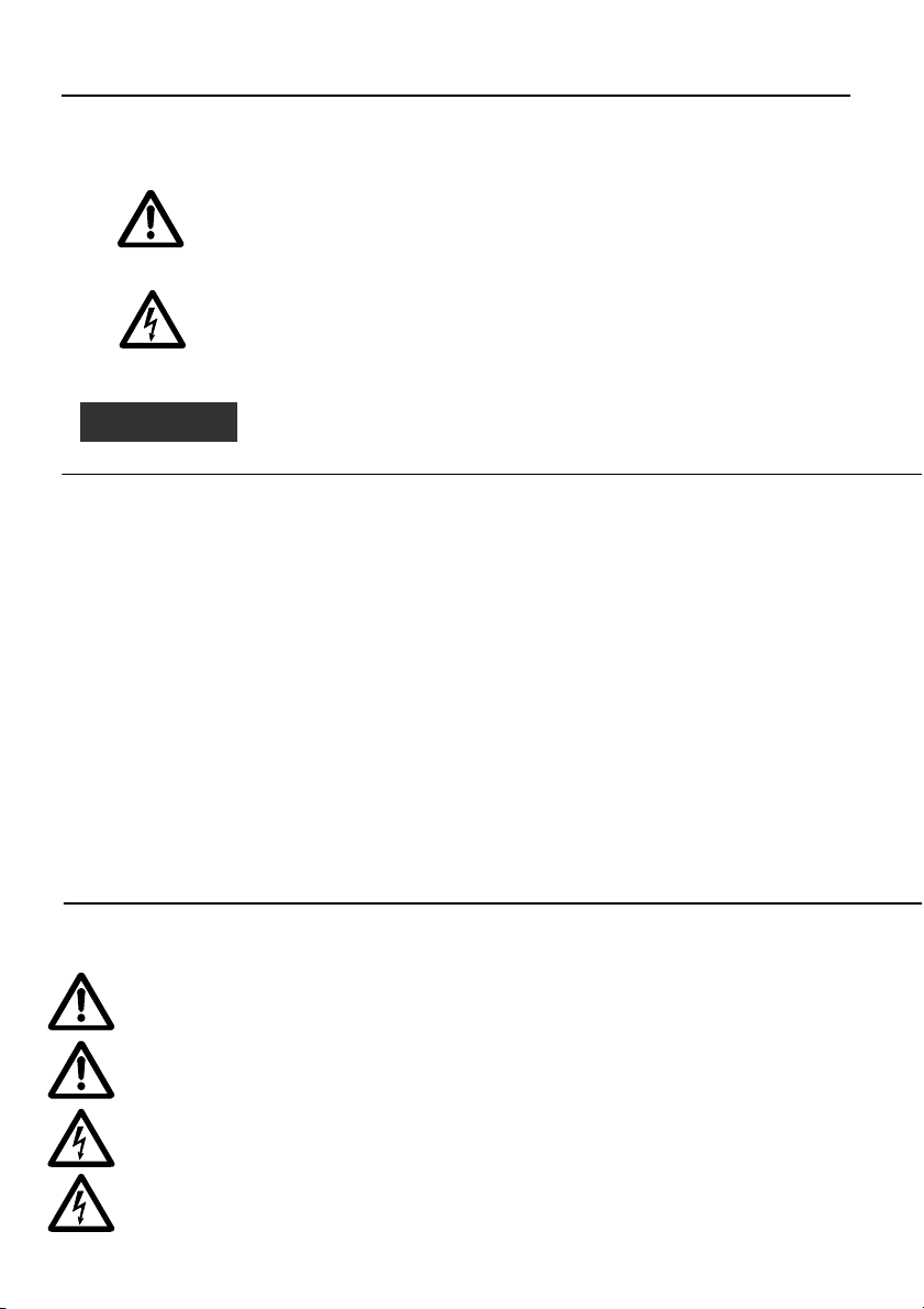
CAUTION
CAUTIONCAUTION
CAUTION
en
enen
SAFETY WARNINGS FOR PERSONS AND PROPERTY
SAFETY WARNINGS FOR PERSONS AND PROPERTY
SAFETY WARNINGS FOR PERSONS AND PROPERTYSAFETY WARNINGS FOR PERSONS AND PROPERTY
The symbols used are shown below
ENGLISH INSTRUCTIONS INDEX
ENGLISH INSTRUCTIONS INDEX
ENGLISH INSTRUCTIONS INDEX ENGLISH INSTRUCTIONS INDEX
DANGER
Risk of injury to persons and property if the requirements are not
observed.
ELECTRIC SHOCK
Risk of electric shock if the requirements are not observed.
WARNING
Risk of damage to property or to the environment if the
requirements are not observed.
1 GENERAL INFORMATION 31
2 PRODUCT DESCRIPTION 31
3 OPERATION 31
4 INSTALLATION 33
5 GENERAL SETTINGS 36
6 PROGRAMMING 37
7 ALARMS 50
8 PARAMETER STRUCTURE 52
9 FIELD BUS 53
10 ELECTRONIC BOARD MAINTENANCE 54
11- REPAIRS - SPARE PARTS 54
12 TROUBLESHOOTING 55
13 TAKING OUT OF SERVICE 55
This manual consists of two parts, the first is intended for the installer and the user, the second only for
the installer.
Before starting installation, read these instructions carefully and abide by local regulations.
Installation and maintenance must be carried out by qualified personnel.
The booster set is an automatic machine, the pumps may start automatically without warning.
The set contains water under pressure, reduce the pressure to zero before intervention.
Make the electrical connections in compliance with the regulations.
Ensure that there is an efficient earth system.
Before doing any work on the set, disconnect the electric power supply.
If the set is damaged, disconnect the electric power supply to avoid electric shocks.
30
Page 31

en
The stored prog
ramme (Software) operates the pumps
CAUTION
CAUTIONCAUTION
CAUTION
1111
2222
3333
4444
en
en en
1 GENERAL INFORMATION
1 GENERAL INFORMATION
1 GENERAL INFORMATION1 GENERAL INFORMATION
Lowara series GSD and GSY booster sets are designed to transfer and increase the pressure of clean water
in plumbing systems in homes, offices, communities and industry.
This manual describes the programming of the electronic control board, referred to below as SM30
BSETF3. For the instructions for use and maintenance of the booster set, see the respective manual.
Characteristics and Limits of use
Characteristics and Limits of use
Characteristics and Limits of useCharacteristics and Limits of use
Rated using voltage of the SM30 BSETF3 board: 24 Vac/Vdc +/- 15%
Absorption: 4 VA max (approx. 0.5 VA in stand-by)
Using and storage environment temperature: -10 °C + 65 °C
Relative humidity: 30% at 90 °C MAX, without condensation
Environment: Internal
IP protection rating of front panel: IP65
Dusty environments with the presence of sand, or damp environments such as at the seaside, may cause
premature deterioration, compromising regular operation.
CHECKING THE MATERIAL
CHECKING THE MATERIAL
CHECKING THE MATERIALCHECKING THE MATERIAL
On delivery of the booster set, check that the material received corresponds to what is indicated on the
transport documents that accompany it.
KEEP ALL THE DOCUMENTATION SUPPLIED WITH CARE.
KEEP ALL THE DOCUMENTATION SUPPLIED WITH CARE.
KEEP ALL THE DOCUMENTATION SUPPLIED WITH CARE.KEEP ALL THE DOCUMENTATION SUPPLIED WITH CARE.
PAPER DOCUMENTATION MUST NOT BE KE
PAPER DOCUMENTATION MUST NOT BE KEPT IN A DAMP PLACE!
PAPER DOCUMENTATION MUST NOT BE KEPAPER DOCUMENTATION MUST NOT BE KE
PT IN A DAMP PLACE!
PT IN A DAMP PLACE!PT IN A DAMP PLACE!
2 PRODUCT DESCRIPTION
2 PRODUCT DESCRIPTION
2 PRODUCT DESCRIPTION2 PRODUCT DESCRIPTION
Electronic control board with LCD display, warning light and control buttons, fitted in the booster set
electric panel.
3 OPERATION
3 OPERATION
3 OPERATION3 OPERATION
by means of the electric panel according to the system
demand.
The LCD display gives indications on the system
operating status, along with the warning leds:
1) LINE: Green led, supply voltage present;
2) FAULT: Red led, indicating a fault;
3) LOW LEVEL: Red led, presence of low pressure/level
alarm on intake;
4) P
: Green led; pump operating;
1
….
P3 operating.
The number of pumps depends on those present in the
set.
31
Page 32

en
en
en en
Symbol Name Description
↑UP/SU
↓DOWN /GIU’
OK/MENU’
P1, P2, P3
Manual Mode
Manual Mode
Manual ModeManual Mode
In Manual mode the pumps may be started and stopped with the P1/ON-OFF, P2/ON-OFF, P3/ON-OFF
keys and there is no pressure regulation.
The controls for minimum pressure switch, minimum level alarm, maximum pressure threshold alarm,
minimum pressure threshold alarm, alarm block from outside, are deactivated.
Automatic Mode
Automatic Mode
Automatic ModeAutomatic Mode
In automatic mode the pumps are controlled by the SM30 BSETF3 board according to the demand
received from the pressure sensor or from the pressure switch consent, to keep the pressure at the
desired level.
In order to operate correctly, the board must be programmed with the system parameters.
Whenever the board is switched on, the default mode is automatic.
Programming
Programming
ProgrammingProgramming
The board is programmed by modifying the parameters in two menus, the Parameters Menu and the
Service Menu.
A third menu allows the display of the alarms that have occurred. The Alarms Log menu is accessible in
both automatic and manual mode.
Parameters menu
Parameters menu
Parameters menuParameters menu
The SM30 BSETF3 electronic board is supplied already programmed, however it may be necessary
to modify some parameters for better operation. The Parameters programming menu contains the
system parameters (number of pumps, presence of jockey pump, choice between system with
pressure sensor and system with pressure switches, default, complete list see chapter 6).
Service menu
Service menu
Service menuService menu
In this menu it is possible to change the language and enable changing of the following
parameters in automatic operation: pump START/STOP working thresholds, probe sensitivity,
timing, compensation of leaks.
Switch between Automatic and Manual mode
Scroll windows up
Increase by one value during “edit data”
Scroll windows down
Decrease by one value during “edit data”
Confirm menu
Confirm data inserted
Manual mode, start (ON) and stop (OFF) pump “n”.
The P3 key also has the (EXIT) function and
acknowledges/switches off the FAULT led
32
Page 33

CAUTION
CAUTIONCAUTION
CAUTION
INFORMATION FOR THE INSTALLER
4 INSTALLATION
4 INSTALLATION
4 INSTALLATION4 INSTALLATION
The board is supplied already connected in the panel and programmed; if it is necessary to alter the
settings, see the Settings chapter. For the connections, refer to the diagram of the electric panel.
4.1 View of terminals
4.1 View of terminals
4.1 View of terminals4.1 View of terminals
A B
H
G
Do not start the pumps until they have been filled with liquid. See the pump
instructions manual.
For connection details, see diagram of electric panel.
Group A
Group B Optoinsulated digital inputs
D
C
EF
Group C Alarm relay
Group D Pump relay control
Group E Bus RS485 communication
Group F Level control
Group G Analog inputs/outputs
Group H Power supply +24 Vac/dc +/-
RILS 6
Optoinsulated digital inputs
15%
RILS board connection
en
en
en en
33
Page 34

en
en
en en
4.1.1 Group A, B optoinsulated digital inputs
4.1.1 Group A, B optoinsulated digital inputs
4.1.1 Group A, B optoinsulated digital inputs4.1.1 Group A, B optoinsulated digital inputs
N° Code Description
1 COM Common terminal for ON/OFF digital inputs
2 PR1 Pump 1 control pressure switch
3 PR2 Pump 2 control pressure switch
4 PR3 Pump 3 control pressure switch
5 TERM1 Thermal protection / PTC pump 1
6 TERM2 Thermal protection / PTC pump 2
7 TERM3 Thermal protection / PTC pump 3
8 AUX1 Auxiliary contact 1, configurable as max. pressure pressure-switch or external
9 AUX2 Auxiliary contact 2, configurable as external consent (NO) or external alarm
10 AUX3 Auxiliary contact 3, configurable as change set (NO) or CONV.L.SWITCH
Characteristics:
Characteristics:
Characteristics:Characteristics:
4.1.2 Group C, relay output and output+12Vdc
4.1.2 Group C, relay output and output+12Vdc
4.1.2 Group C, relay output and output+12Vdc 4.1.2 Group C, relay output and output+12Vdc
N° Code
11 NO Alarm Relay / Solenoid valve contact output, 30 Vac max 1 A
12 COM Alarm Relay / Solenoid valve common output
13 +12Vdc Alarm Output +12 Vdc, 50 mA
14 GND Alarm Output +12 Vdc, ground
4.1.3 Group D, pump relay control
4.1.3 Group D, pump relay control
4.1.3 Group D, pump relay control4.1.3 Group D, pump relay control
N° Code
15 P1 Pump 1 contactor control relay output
16 P2 Pump 2 contactor control relay output
17 P3 Pump 3 contactor control relay output
18 COM Pump control circuit common output
Contact characteristics:
Contact characteristics: 30 Vac max 1A
Contact characteristics:Contact characteristics:
4.1.4 Group E, RS485 user interface
4.1.4 Group E, RS485 user interface
4.1.4 Group E, RS485 user interface4.1.4 Group E, RS485 user interface
N° Code
A RS485
19
B RS485
20
GND
21
auto-test command
(NC).
(Minimum Pressure Switch)
Threshold OFF= current with input closed = 4mA
Description
Description
Description
Field bus com.
Field bus com.
Ground
34
Page 35

4.1.5 Group F, level co
4.1.5 Group F, level control
4.1.5 Group F, level co4.1.5 Group F, level co
N° Code
22 HIGH High level probe / float / minimum pressure switch input
23 LOW Low level probe input
24 COM Probes / float / minimum pressure switch common circuit
Characteristics:
Characteristics:
Characteristics:Characteristics:
Voltage 3.6Vp-p
4.1.6 Group G, analog inputs/outpu
4.1.6 Group G, analog inputs/outputs
4.1.6 Group G, analog inputs/outpu4.1.6 Group G, analog inputs/outpu
N° Code
25 GND_A Sensor cable screen connection electronic ref.
26 Out_A Analog signal output
27 AI1 Sensor 1 active value input
28 AI2 Sensor 2 active value input
29 PWR_A Sensor power supply +13.5 Vdc
Characteristics:
Characteristics:
Characteristics:Characteristics:
Voltage 0-11 V, accuracy 0.3%;
Current input 0-22 mA, accuracy 0.3%, protection against short circuit.
Maximum input voltages = 30 Vdc.
4.1.7 Group H, Power supply
4.1.7 Group H, Power supply
4.1.7 Group H, Power supply4.1.7 Group H, Power supply
N° Code
30 PE Earth connection
31 0Vac Board power supply
32 24Vac Board power supply
Characteristics:
Characteristics:
Characteristics:Characteristics:
Voltage 24Vac +/-10%
Frequency 50/60Hz
4.2 View of bypass jumpers
4.2 View of bypass jumpers
4.2 View of bypass jumpers4.2 View of bypass jumpers
The bypass jumpers bypass the electronics, directly activating the pump control contactors without any
regulating control.
They are used in an emergency, when the electronic board is out of use and it is necessary to ensure
pump operation.
OPEN position = The pump contactors are deactivated.
CLOSE position = The pump contactors are permanently activated and no regulating control is carried
out (to be used only in emergency situations).
SOFTWARE position = pump contactors controlled by the electronic board.
The default position of the jumpers is SOFTWARE.
ntrol
ntrolntrol
Description
Description
Description
ts
tsts
en
en
en en
35
Page 36

en
CAUTION
CAUTIONCAUTION
CAUTION
en
en en
5 GENERAL SETTINGS
5 GENERAL SETTINGS
5 GENERAL SETTINGS5 GENERAL SETTINGS
5.1 Automatic / man
5.1 Automatic / manual mode
5.1 Automatic / man5.1 Automatic / man
When switched on the electronic board is set in automatic mode.
In the case of a system with a pressure sensor, this window appears:
AUTO
##.## is the current pressure value.
In the case of a system with pressure switches, this window appears
AUT: PRESSURE SW
It is possible to pass from AUTOMATIC to MANUAL mode, and vice versa, by pressing the ↑UP button.
In MANUAL and AUTOMATIC mode the Alarms Log can be displayed by pressing the ↑UP and OK/MENU
buttons simultaneously. The following window appears
ALARMS
From AUTOMATIC mode (if enabled in the System Menu) or MANUAL mode, the parameters setting
menu can be accessed by pressing the ↓DOWN and OK/MENU buttons simultaneously.
5.2 General rules for mod
5.2 General rules for modifying and inserting data
5.2 General rules for mod5.2 General rules for mod
In a menu, use the ↑UP and ↓DOWN buttons to move from one window to another. Each window refers
to a single parameter to be set or to a submenu.
For each window a default value is proposed which may be modified as required.
To modify a parameter or access a submenu, in a window, press the OK/MENU button.
The parameter to be changed appears between two square brackets [ ] if it is part of a list, while for
numerical values a blinking cursor indicates the figure to be changed; in both cases, use the ↑UP and
36
The adjustments may influence correct operation of the set.
ual mode
ual modeual mode
AI1 + ###.## bar
ifying and inserting data
ifying and inserting dataifying and inserting data
------------
LOG
Page 37

en
CAUTION
CAUTIONCAUTION
CAUTION
en
en en
↓DOWN buttons to change the value.
If a parameter is a number of several figures, these are changed separately, press OK/MENU to move on
to the next figure.
Once the desired value has been obtained, press OK/MENU to confirm the value or press P3 (ESC) to
cancel.
To leave a menu or a submenu, press P3 (ESC) or repeatedly press the ↑UP or ↓DOWN key until it gives
the message EXIT, select YES and confirm with OK/MENU .
Default Values
Default Values
Default ValuesDefault Values
The default values are those set in the factory and they may be reset on the DEFAULT menu.
6 PROGRAMMING
6 PROGRAMMING
6 PROGRAMMING6 PROGRAMMING
6.1 Service menu
6.1 Service menu
6.1 Service menu6.1 Service menu
Modifications to the service menu must be made by qualified personnel.
When switching on the board, press the OK/MENU and ↑UP buttons until this message appears on the
display:
PASSWORD SERVICE
Set the password 00066 with the ↑UP and ↓DOWN buttons and confirm with OK/MENU to enter the
service menu.
If the password is wrong, the menu is proposed in read-only mode and this window appears:
WRONG PASSWORD
Display Comment Field Default
LANGUAGE Language setting.
AUTO ENABLE Modification of some parameters enabled in
The adjustments may influence correct operation of the set.
[00066]
READ ONLY
Some languages may not be active, in this
case the messages are automatically displayed
in Italian.
AUTOMATIC mode.
ITALIANO,
ENGLISH,
FRANÇAIS,
DEUTSCH,
PORTUGUÊS,
ESPANÕL
YES
NO
ITALIANO
NO
37
Page 38

en
Type of sensor used:
Pressure switches
PRESS. SENSOR
en
en en
6.2 Parameters menu
6.2 Parameters menu
6.2 Parameters menu6.2 Parameters menu
The machine configuration and control parameters are inserted from the keyboard during the adjustment
and testing operations performed in the factory, but they may be changed later. As the set cannot be
used during the parameter inserting operations, it is necessary to close the stop valve on the delivery
manifold, or all the utilities.
Switch on the electric panel; by default, the system is set in automatic mode. It is possible to pass from
AUTOMATIC to MANUAL mode, and vice versa, by pressing the ↑UP button.
In the case of a system with a pressure sensor, this window appears:
AUTO
##.## is the current pressure value.
In the case of a system with pressure switches, this window appears
AUT: PRESSURE SW
Press the ↓DOWN and OK/MENU buttons until this message appears on the display:
PASSWORD PARAM.
Set the password 00066 with the ↑UP and ↓DOWN buttons and confirm with OK/MENU to enter the
parameters menu.
If the password is wrong, the menu is proposed in read-only mode and this window appears:
WRONG PASSWORD
6.2.1 SYSTEM
6.2.1 SYSTEM
6.2.1 SYSTEM6.2.1 SYSTEM
Phase
0000
1 PUMPS NUMBER Total number of pumps including
2 JOCKEY PUMP Indicate presence of jockey pump YES
3 CONTROLLED BY
Display Comment Field Default
SYSTEM
SYSTEM
SYSTEMSYSTEM
any jockey pump.
Pressure sensor
Temperature sensor
Flow sensor
Level sensor
AI1 + ###.## bar
-----------
[00066]
READ ONLY
1
2
3
NO
TEMP.SENSOR
FLOW SENSOR
LEVEL SENSOR
PRESS. SWITCHES
3
NO
PRESS.
SENSOR
38
Page 39

en
en
en en
4 SENSOR F.S. Sensor full scale: this is defined by
5 LACK OF WATER Device used to check low level/low
6 PROBES SENSIVITY Regulating probe sensitivity
7 FEEDBACK Setting the analog signal used as
Regulating probe sensitivity
Regulating probe sensitivity
Regulating probe sensitivityRegulating probe sensitivity
Regulation is obtained by setting the sensitivity value. For a new regulation, proceed as follows:
Check that the water level covers the probes.
Ensure that L.O.W. AL.DELAY is set at zero.
Vary the sensitivity level slightly until the red “LOW WATER” led is lit and the respective alarm message
appears.
Slightly increase the numerical value of sensitivity until the red “LOW WATER” led goes out.
the type of sensor chosen.
Pressure
0-10 bar
0-16 bar
0-25 bar
0-50 bar
Level
Ultrasound: 0-15 m
Piezometric: 0-10 m
Temperature
-200 + 850 °C
Flow
DN80 3.62-181 mc/h
DN100 5.65-283 mc/h
DN125 8.84-442 mc/h
DN150 12.7-637 mc/h
DN200 22.6-1131 mc/h
DN250 35.3-1727 mc/h
pressure with
probes/float/minimum pressure
switch connected to the dedicated
terminals HIGH (22), LOW(23) and
COM(24).
according to water conductivity.
system feedback.
If AI1 or AI2 is selected, in case of a
sensor fault feedback is
automatically provided by the
alternative sensor.
0-10 bar
0-16 bar
0-25 bar
0-50 bar
Ultras 0-15 m
Piezom 0-10 m
NO PROBES
PR.SW/FLOAT SW
THREE PROBES
5-100 kOhm 50 kOhm
AI1
AI2
AI1/AI2
0-10.00 bar
PR.SW/FLOA
T SW
AI1/AI2
39
Page 40

en
en
en en
6.2.2 PUMP START/STOP THRESHOLDS
6.2.2 PUMP START/STOP THRESHOLDS
6.2.2 PUMP START/STOP THRESHOLDS6.2.2 PUMP START/STOP THRESHOLDS
Note: The THRESHOLDS parameters can be set only with a system with a pressure or level sensor.
The thresholds must be set considering the hydraulic performances of the pump (curve Q-H) and of the
type of system.
Phase
0000
1 P1 STOP THRESH.
2 P1 START THRESH.
3 P2 STOP THRESH.
4 P2 START THRESH.
5 P3 STOP THRESH.
6 P3 START THRESH.
6.2.3 PUMPS STARTING ROTATION
6.2.3 PUMPS STARTING ROTATION
6.2.3 PUMPS STARTING ROTATION6.2.3 PUMPS STARTING ROTATION
Phase
0000
1 PUMPS ROTATION Enable pump rotation.
2 PUMP SEQUENCE Insert the duty pump that you want to start
3 SWITCH INTERVAL If automatic pump rotation does not take place
NOTE: The jockey pump, if present, is not subject to rotation and is started first, it remains on when the
duty pumps start and it switches off last.
Display Comment Field Default
THRESHOLDS
THRESHOLDS Application with pressure / level
THRESHOLDSTHRESHOLDS
Display Comment Field Default
PUMPS ROTATION
PUMPS ROTATION
PUMPS ROTATIONPUMPS ROTATION
Application with pressure / level
Application with pressure / levelApplication with pressure / level
Stop (OFF) threshold (pressure/level) for
pump 1
Start (ON) threshold (pressure/level) for
pump 1
Stop (OFF) threshold (pressure/level) for
pump 2
Start (ON) threshold (pressure/level) for
pump 2
Stop (OFF) threshold (pressure/level) for
pump 3
Start (ON) threshold (pressure/level) for
pump 3
Set YES to activate pump rotation. Automatic
pump rotation takes place each time the set is
restarted after stopping in automatic mode.
The jockey pump, if present, is not subject to
rotation, so it always starts first.
first after electrically switching on the set.
In systems with a jockey, as this is P1, the first
duty pump that can be set can only by P2 or
P3.
(the set has never been able to stop), after the
set time a “forced” rotation of the duty pumps
is performed (excluding the jockey).
To disable this function set 0h
0.. FS +3.50 bar
0.. FS +2.70 bar
0.. FS +3.40 bar
0.. FS +2.60 bar
0.. FS +3.30 bar
0.. FS +2.50 bar
YES
NO
P1
P2
P3
0 h
1÷12 h
YES
P1
0 h
40
Page 41

en
en
en en
6.2.4 TIMING
6.2.4 TIMING
6.2.4 TIMING6.2.4 TIMING
Timing is active both with systems with pressure switches and with systems with sensors.
Phase
0000
1 P1 START DELAY
2 P2-3 START DELAY Delay in starting P2 - P3. The time count
3 P1 STOP DELAY Delay in stopping P1 (jockey included).
4 P2-3 STOP DELAY Delay in stopping pumps P2 - P3. The
5 DYNAMIC TIMES Settable only on system with sensor.
6.2.5 PERIODIC AUTO TEST
6.2.5 PERIODIC AUTO TEST----RUN
6.2.5 PERIODIC AUTO TEST6.2.5 PERIODIC AUTO TEST
In systems subject to long periods of inactivity it is recommended to perform a periodic automatic test
(auto test-run) with the aim of checking the performances of the group.
In any case the autotest cannot replace programmed maintenance, which must be carried out
periodically. A weekly interval is recommended.
To start the test request the board’s internal clock may be used, or an external command. When autotest
is enabled, the alarm relay is automatically configured to control the solenoid valve.
It is also necessary to ensure that the parameter CONFIG. IN. AUX3 in the DIGITAL IN/OUT MENU is set as
CONV.L.SWITCH (Minimun Pressure Switch).
Phase
0000
1 AUTO TEST REQ. Autotest command source.
Display Comment Field Default
TIMING
TIMING
TIMINGTIMING
Display Comment Field Default
AUTO
AUTO----TEST
TEST RUN
AUTOAUTO
RUN
TESTTEST
RUN RUN
Delay in starting P1 (jockey included).
The time count begins from the start
request from the pressure switch/sensor.
begins from the start request from the
pressure switch/sensor.
The time count begins from the stop
request from the pressure switch/sensor.
time begins from the stop request from
the pressure switch/sensor.
Halves the times previously set in the
case of excessive variation of the
pressure/level/etc. of the system.
RUN
RUNRUN
The possible settings are:
Disabled: autotest is inhibited.
Internal clock: autotest is activated on
the day and time requested from the
SM30 BSETF3 board by the internal
clock.
Ext. command: autotest is activated by
the external command connected to the
digital input AUX1
0..100 s 3 s
0..100 s 5 s
0..100 s 5 s
0..100 s 3 s
YES
NO
DISABLED
INTERNAL
CLOCK
EXT.ON /OFF
DISABLED
NO
41
Page 42

en
en
en en
2 DAY
3 HOUR Setting of the hour when autotest is to
4 MINUTES Setting of the minutes when autotest is
How to st
How to start autotest
How to stHow to st
The periodic autotest is activated by:
If the request arrives during operation of the pumps, autotest will be put in standby and this message
will appear at regular intervals:
AUTO
As soon as the set has all the pumps off, autotest will start with the following message
AUTOTEST P1
During the pause between testing one pump and the other the following message appears:
AUTOTEST STAND
If the autotest has had a negative result the following message appears:
AUTO
Autotest execution phases
Autotest execution phases
Autotest execution phasesAutotest execution phases
The test is composed of the sequences:
a) Receiving the command.
b) Opening the solenoid valve on the set by the control of the SOLENOID VALVE relay.
c) Starting the first pump.
d) Closing the solenoid valve.
e) Stopping the pump being tested after two minutes.
f) Waiting one minute.
g) Performing test on next pump.
art autotest
art autotestart autotest
- an external command, connected to the digital input AUX1
or
- the board internal clock
Setting of the day autotest is to be
performed (parameter active only if the
command source is set as INTERNAL
CLOCK)
be performed (parameter active only if
the command source is set as INTERNAL
CLOCK)
to be performed (parameter active only if
the command source is set as INTERNAL
CLOCK)
AUTOTEST PENDING
AI1 +###.## bar
AI1 +###.## bar
AUTOTEST FAIL P#
MON
..SUN
0..24 h 10
0..60 min 00
MONDAY
42
Page 43

en
SUP
INF
1 pompa
2 pompe
3 pompe
Incremento
Soglie variabili per compensazione perdite di carico
Increase
1 pump
2
pumps
3
pumps
Variable thresh
olds to compensate load losses
UPPER
LOWER
en
en en
When the autotest has failed
When the autotest has failed
When the autotest has failedWhen the autotest has failed
If during the autotest (whatever pump is operating) the minimum pressure switch (CONV.L.SWITCH)
installed on the set trips, the autotest is definitively interrupted and the set resumes working in automatic
mode.
The display shows the message AUTOTEST FAIL P#.
CONV.L.SWITCH intervention is delayed by the time set on the parameter AUX3 IN DELAY.
How to interrupt the autotest
How to interrupt the autotest
How to interrupt the autotestHow to interrupt the autotest
To interrupt the autotest, press the button P3 (ESC).
6.2.6 LOAD LOSS COMPENSATION
6.2.6 LOAD LOSS COMPENSATION
6.2.6 LOAD LOSS COMPENSATION6.2.6 LOAD LOSS COMPENSATION
Sometimes in the systems there is a fall in pressure caused by load losses along the pipes and these
increase when the required water flow increases.
Phase
0000 COMPENSATION
Display Comment Field Default
COMPENSATION Available only with systems with a
COMPENSATIONCOMPENSATION
pressure sensor
1 COMP.THRESHOLD Enable load loss compensation with
increase of the start and stop thresholds
000.00 bar 000.00
bar
in bar for the pumps after the first.
Setting pressure = 0 bar disables the
function.
To compensate system load losses it is possible to enable a control that supplies a pressure proportional
to the load. A direct measurement of the flow is not taken, but it is believed that it is proportional to the
number of pumps running.
When each duty pump after the first is started, the UPPER and LOWER thresholds are increased by the
value indicated in the COMP. THRESHOLD parameter.
The jockey pump is excluded.
ON
ON
ON
ON
ON
ON
6.2.7 PROGRAMMING THE ALARM RELAY
6.2.7 PROGRAMMING THE ALARM RELAY
6.2.7 PROGRAMMING THE ALARM RELAY6.2.7 PROGRAMMING THE ALARM RELAY
The SM30 BSETF3 board has an output alarm relay which is activated as described below for the
following types of alarms:
The alarm rel
The alarm relay is available and programmable only and exclusively if the AUTOTEST function has not
The alarm relThe alarm rel
been enabled.
been enabled.
been enabled.been enabled.
If AUTOTEST is enabled, the parameters described below will not be displayed.
If AUTOTEST is enabled, the parameters described below will not be displayed.
If AUTOTEST is enabled, the parameters described below will not be displayed.If AUTOTEST is enabled, the parameters described below will not be displayed.
ay is available and programmable only and exclusively if the AUTOTEST function has not
ay is available and programmable only and exclusively if the AUTOTEST function has not ay is available and programmable only and exclusively if the AUTOTEST function has not
43
Page 44

en
en
en en
Phase
0000
1 DELAY ON RELAY Delay in seconds of alarm relay
2 DELAY OFF RELAY Delay in seconds of alarm relay
3 LOGIC RELAY Active: for event =ON
4 DISABLE RELAY Automatic when the alarm ceases or
5 RELAY ON O.L. PUMP OVERLOAD ALARM
6 RELAY ON L.O.W. LOW WATER ALARM
7 RELAY ON SENSOR SENSOR ALARM
8 RELAY ON C.LIMIT CONVEYOR LIMIT
9 RELAY ON EXT.AL. EXTERNAL FAULT ALARM
10 RELAY ON MAX P. MAX PRESSURE ALARM
11 RELAY ON MIN P. MINIMUM THRESHOLD ALARM
6.2.8 PROGRAMMING THE ALARMS
6.2.8 PROGRAMMING THE ALARMS
6.2.8 PROGRAMMING THE ALARMS6.2.8 PROGRAMMING THE ALARMS
Phase
0000
1 MIN.PRES.THRES
44
Display Comment Field Default
ALARM RELAY
ALARM RELAY
ALARM RELAYALARM RELAY
activation
deactivation
The contact is open in case of event
Passive: for event =OFF
The contact is closed in case of event
manually with button P3 (EXIT)
Activates alarm relay for tripping of an
overload/ptc of any active pump.
Activates alarm relay for low
level/pressure on intake through
probes/float/min. pressure switch
Activates relay for fault in activated
sensors.
Activates relay for Minimum Pressure
Switch alarm (connected to digital
input AUX3, to be set as
CONV.L.SWITCH)
Activates relay for external fault arriving
from digital input AUX2.
Activates relay for maximum pressure
alarm arriving from digital input AUX1
or from MAX.PRES.THRESH.
Activates relay for minimum pressure
threshold alarm.
Display Comment Field Default
ALARMS
ALARMS
ALARMSALARMS
H.
MINIMUM PRESSURE ALARM
Function available only with systems with a
pressure sensor.
Set the minimum pressure value below
which the system interrupts pump
operation.
The system control is performed only if at
least one pump is active.
To disable, insert pressure = 0 bar
0..60 s 0 s
0..60 s 0 s
ACTIVE
PASSIVE
AUTOMATIC
MANUAL
YES
NO
YES
NO
YES
NO
YES
NO
YES
NO
YES
NO
YES
NO
0..FS bar 0 bar
PASSIVE
AUTOMATIC
YES
YES
YES
NO
NO
NO
NO
Page 45

2 MIN.PRES.DELAY Function available only with systems with a
3 MAX.PRES.THRES
H.
4 MAX.PRES.DELAY Function available only with systems with a
5 EXT.AL. DEFINE EXTERNAL FAULT ALARM
6 P1 OVERLOAD P1 OVERLOAD ALARM
7 P2 OVERLOAD P2 OVERLOAD ALARM
8 P3 OVERLOAD P3 OVERLOAD ALARM
9 LOW WATER
ALARM
10 L.O.W. AL.DELAY Delay time in seconds to block pumps for
11 CONVEYOR LIMIT CONVEYOR LIMIT
12 ALARMS RESET Resets the memory of the Alarms Log. YES
Adjusting the
Adjusting the Minimum Pressure Switch Alarm (
Adjusting the Adjusting the
The minimum pressure switch is positioned on the delivery manifold and must be set at the system
minimum pressure, about 0.5 bar below the starting pressure value of the last pump.
Minimum Pressure Switch Alarm (CONV.L.SWITCH
Minimum Pressure Switch Alarm (Minimum Pressure Switch Alarm (
pressure sensor and only if the respective
alarm is enabled (previous parameter).
Delay time in seconds on blocking
intervention for minimum pressure.
MAX PRESSURE ALARM
Function available only with systems with a
sensor.
Maximum pressure beyond which all the
active pumps are switched off.
To disable, insert pressure = 0 bar
sensor and if the respective alarm is
enabled (previous parameter).
Delay time in seconds on blocking
intervention for exceeding maximum
pressure.
Configuration of the indication of an
external alarm connected to digital input
AUX2. Usually a temperature or voltage
overload alarm generated by an external
trip device.
Intervention of thermal protection / PTC
pump 1
Intervention of thermal protection / PTC
pump 2
Intervention of thermal protection / PTC
pump 3
LOW WATER ALARM
Intervention of hardware protection for low
level/pressure on intake
From probe circuit HIGH. LOW, COM to
terminals 22 – 23- 24
intervention of protection for low
level/pressure on intake.
Tripping of protection against pump
operation below minimum pressure.
Signal arrives from minimum pressure switch
(CONV.L.SWITCH) connected to digital input
AUX3.
CONV.L.SWITCH))))
CONV.L.SWITCHCONV.L.SWITCH
0..200 s 20 s
0..FS bar 0 bar
0..10 s 0 s
OVERTEMPER
ATURE
OVERVOLTAGE
EXT.TRIP
DEVICE
THERMAL PR.
PTC
DISABLED
THERMAL PR.
PTC
DISABLED
THERMAL PR.
PTC
DISABLED
YES
NO
10…100 s 10 s
YES
NO
NO
OVERVOLTAGE
THERMAL PR.
THERMAL PR.
THERMAL PR.
YES
YES
NO
en
en
en en
45
Page 46

en
Visible only if 4
-
20mA selected.
ADJUST KO appears
en
en en
Set the delay time at zero (parameter AUX3 IN DELAY in the DIGITAL IN/OUT MENU) of the minimum
pressure switch alarm. With the system under pressure, inhibit pump operation with the bypass jumpers
on the board (see chapter 4.2).
Configure the set to work in automatic mode. Slowly open a drawing point to bring down the pressure
in the delivery manifold. As the pressure lowers, the pump leds will light; the pumps will not start
because operation has been inhibited. When the established pressure value (minimum pressure) is
reached, turn the regulating screw on the minimum pressure switch to modify the threshold of
intervention (turn clockwise to increase the threshold, counter clockwise to decrease it). The lighting of
the red fault led and the respective alarm on the display indicate intervention of the protection device.
On completing adjustment, reset the CONV.L.SWITCH alarm delay (recommended 20 seconds) in the
parameter AUX3 IN DELAY in the DIGITAL IN/OUT MENU.
6.2.9 NIGHT/DAY FUNCTION
6.2.9 NIGHT/DAY FUNCTION
6.2.9 NIGHT/DAY FUNCTION6.2.9 NIGHT/DAY FUNCTION
Phase
0000
1 NIGHT/DAY FUNC. Threshold change enable in N mode (night-
2 NIGHT/DAY VALUE Decrease value of the pressure SET when
3 N/D START HOUR Setting of the hour for activating the N/D
4 N/D START MIN. Setting of the minutes for activating the N/D
5 N/D END HOUR Setting of the hour for deactivating the N/D
6 N/D END MIN. Setting of the minutes for deactivating the
6.2.10 PROGRAMMING ANALOG INPUTS / OUTPUTS
6.2.10 PROGRAMMING ANALOG INPUTS / OUTPUTS
6.2.10 PROGRAMMING ANALOG INPUTS / OUTPUTS6.2.10 PROGRAMMING ANALOG INPUTS / OUTPUTS
Phase
0000
1 AI1 SENSOR TYPE Type of transducer connected to the
2 ZERO ADJUST AI1
Display Comment Field Default
NIGHT/DA
NIGHT/DAY
NIGHT/DANIGHT/DA
ANALOG. IN/OUT
ANALOG. IN/OUT Only for systems with a sensor
ANALOG. IN/OUTANALOG. IN/OUT
Y Only for systems with a sensor
Y Y
Display Comment Field Default
Only for systems with a sensor
Only for systems with a sensorOnly for systems with a sensor
time).
May be disabled by the internal clock, by an
external control connected to AUX3, or by
the Internal Clock or External control.
working in N (night) mode. When night-time
operation is enabled, all the thresholds are
decreased by the value set in this parameter.
The letter N is highlighted at top right of the
display.
change.
change.
change.
N/D change.
Only for systems with a sensor
Only for systems with a sensorOnly for systems with a sensor
analog input AI1 (if selected on System)
Acquisition of input zero 4 4-20 mA
Adjustment is possible only in the range
3.5… 4.5mA
If adjustment has a positive result the
message SENSOR ADJUST OK appears
If out of range the message SENSOR
DISABLED
INTERNAL
CLOCK
EXT.ON
/OFF
INT.EXT
-FS..0..FS -1.00 bar
4-20 mA
0-20 mA
0-10 V
0-2 V
YES
NO
DISABLED
4-20 mA
NO
46
Page 47

3 AI1 FILTER Software filter (no. samples) of the
4 AI1 UNIT Setting the unit of measurement on
5 AI2 SENSOR TYPE Type of transducer connected to the
6 ZERO ADJUST AI2 Visible only if 4-20mA selected.
7 AI2 FILTER
8 AI2 UNIT Setting the unit of measurement on
9 ANALOG OUTPUT Function that can be attributed to analog
10 AN.OUT1 TYPE Full scale analog output AO1 4-20 mA
6.2.11 PROGRAMMING DIGITAL INPUTS / OUTPUTS
6.2.11 PROGRAMMING DIGITAL INPUTS / OUTPUTS
6.2.11 PROGRAMMING DIGITAL INPUTS / OUTPUTS6.2.11 PROGRAMMING DIGITAL INPUTS / OUTPUTS
Phase
0000
1 PR.SW.1 LOGIC Terminal 2 only if pressure switch
2 PR.SW.2 LOG Terminal 3 only if pressure switch
3 PR.SW.3 LOGIC Terminal 4 only if pressure switch
4 CONFIG. AUX1 IN. Configuration of input AUX1 as max.
5 CONFIG. AUX2 IN. Configuration of input AUX2 as external
Display Comment Field Default
DIGITAL IN / OUT
DIGITAL IN / OUT
DIGITAL IN / OUTDIGITAL IN / OUT
analog input AI1 signal
input AI1
analog input AI2 (if selected on System)
Acquisition of input zero 4 4-20 mA
Adjustment is possible only in the range
3.5… 4.5mA
If adjustment has a positive result the
message SENSOR ADJUST OK appears
If out of range the message SENSOR
ADJUST KO appears
Software filter (no. samples) of the
analog input AI2 signal
input AI2
output Out_A
operation enabled.
operation enabled.
operation enabled.
pressure pressure-switch or external
auto-test command.
consent (NO) or external alarm (NC).
1..199 1
DISABLED
bar
°C
m³/h
m
4-20 mA
0-20 mA
0-10 V
0-2 V
YES
NO
1..199 1
DISABLED
bar
°C
m³/h
m
DISABLED
AI1
AI2
0-20 mA
0-10 V
0-2 V
NC / NO NC
NC / NO NC
NC / NO NC
DISABLED
HIGH
PRESSURE
START
AUTOTEST
DISABLED
EXT.ALARM
EXT.ON/OFF
bar
4-20 mA
NO
bar
DISABLED
4-20 mA
DISABLED
DISABLED
en
en
en en
47
Page 48

en
Allows you to configure the OUT_3
relay of the RILS6 optional board
See
configuration 1
en
en en
6 CONFIG. AUX3 IN. Configuration of input AUX3 as
7 AUX1 IN DELAY Delay time in seconds till
8 AUX2 IN DELAY Delay time in seconds till
9 AUX3 IN DELAY Delay time in seconds till
6.2.12 PROGRAMMING FIELD BUS RS485
6.2.12 PROGRAMMING FIELD BUS RS485
6.2.12 PROGRAMMING FIELD BUS RS485 6.2.12 PROGRAMMING FIELD BUS RS485
Phase
0000
FIELD BUS
FIELD BUS
FIELD BUSFIELD BUS
1 RS485 ENABLE Enable YES
2 MODBUS ADDRESS 1:31 1
3 PARITY None
4 DELAY 0..199 ms 0
5 BAUD RATE 1200
6.2.13 RILS6 BOARD RELAY CONFIGURATION RELAUNCH CLEAN CONTACTS SIGNALS
6.2.13 RILS6 BOARD RELAY CONFIGURATION RELAUNCH CLEAN CONTACTS SIGNALS
6.2.13 RILS6 BOARD RELAY CONFIGURATION RELAUNCH CLEAN CONTACTS SIGNALS6.2.13 RILS6 BOARD RELAY CONFIGURATION RELAUNCH CLEAN CONTACTS SIGNALS
Phase Display Comment Field Default
0000
RILS6 CONFIG.
RILS6 CONFIG.
RILS6 CONFIG.RILS6 CONFIG.
1 REL.OUT1 CONFIG Allows you to configure the OUT_1
2 REL.OUT2 CONFIG Allows you to configure the OUT_2
3 REL.OUT3 CONFIG
Display Comment Field Default
change set (NO) or minimum
pressure switch CONV.L.SWITCH
activation of input AUX1.
Visible only if AUX1 is enabled.
activation of input AUX2.
Visible only if AUX2 is enabled.
activation of input AUX3.
Visible only if AUX3 is enabled.
relay of the RILS6 optional board
relay of the RILS6 optional board
DISABLED
CHANGE SET
CONV.L.SWITCH
0..20 s 0 s
0..20 s 0 s
0..20 s 0 s
NO
Even
Odd
2400
4800
9600
19200
38400
57600
115200
AUT - MAN
P1
P2
P3
THERMAL PR.
LEVEL
MAX P
MIN P
EXT.AL.
AUTOP.KO
POWER ON
See
configuration 1
CONV.L.SWIT
CH
YES
None
38400
P1
P2
P3
48
Page 49

4 REL.OUT4 CONFIG Allows you to configure the OUT_4
5 REL.OUT5 CONFIG Allows you to configure the OUT_5
6 REL.OUT6 CONFIG Allows you to configure the OUT_6
6.2.14 DEFAULT PARAMETERS
6.2.14 DEFAULT PARAMETERS
6.2.14 DEFAULT PARAMETERS6.2.14 DEFAULT PARAMETERS
Phase
0000
1 DEFAULT PARAMETER Loads all the default parameters (factory
6.2.15 PROGRAMMING THE CLOCK
6.2.15 PROGRAMMING THE CLOCK
6.2.15 PROGRAMMING THE CLOCK6.2.15 PROGRAMMING THE CLOCK
Phase
0000
1 SET DATE Setting the date Day
2 SET HOUR Setting the hour and the minutes Hour +
6.2.16 CONFIGURING THE DISPLAY
6.2.16 CONFIGURING THE DISPLAY
6.2.16 CONFIGURING THE DISPLAY6.2.16 CONFIGURING THE DISPLAY
Phase
0000
1 AI1 DISPLAY The display shows the value of AI1 YES
2 AI2 DISPLAY The display shows the value of AI2 YES
3 HOUR/DATE DISPL. The display shows the value of the date
4 BARGRAPH Enables display of the indicating bar on
6.2.17 SOFTWARE
6.2.17 SOFTWARE
6.2.17 SOFTWARE6.2.17 SOFTWARE
Phase Display Comment Field Default
0000
1 VERSION Only reading of program loaded and
Display Comment Field Default
DEFAULT
DEFAULT
DEFAULTDEFAULT
Display Comment Field Default
REAL TIME CLOC
REAL TIME CLOCKKKK
REAL TIME CLOCREAL TIME CLOC
Display Comment Field Default
DISPLAY
DISPLAY
DISPLAYDISPLAY
SOFTWARE
SOFTWARE
SOFTWARESOFTWARE
relay of the RILS6 optional board
relay of the RILS6 optional board
relay of the RILS6 optional board
setting)
and time
input selected as feedback.
Available only on systems with sensors.
release number
See
configuration 1
See
configuration 1
See
configuration 1
YES
NO
Month
Year
Minutes
NO
NO
YES
NO
YES
NO
BSETF3
THERMAL
PR.
LEVEL
POWER ON
YES
YES
NO
NO
REL .01
en
en
en en
49
Page 50

en
Exceeding of set maximum pressure threshold for a
automatic operation; a manual reset is required
.
INFORMATION FOR THE INSTALLER AND USER
en
en en
6.2.18 HOUR COUNTER
6.2.18 HOUR COUNTER
6.2.18 HOUR COUNTER6.2.18 HOUR COUNTER
Phase Display Comment Field Default
0000
HOUR COUNTER
HOUR COUNTER
HOUR COUNTERHOUR COUNTER
1 P1 OPERAT.HOURS Reads pump 1 operating hours 0
2 P2 OPERAT.HOURS Reads pump 2 operating hours 0
3 P3 OPERAT.HOURS Reads pump 3 operating hours 0
4 OP.HOURS RESET Resets memory of pump hour counter
7 ALARMS
7 ALARMS
7 ALARMS7 ALARMS
In MANUAL and AUTOMATIC mode the Alarms Log can be displayed by pressing the ↑UP and OK/MENU
buttons.
All the alarms are indicated and stored in the memory, but some block only automatic operation of the
set.
All the alarms cause the lighting of the red FAULT led.
The alarm for low water level on intake lights the red LOW WATER led.
Alarm display
Alarm display
Alarm displayAlarm display
The last ten alarms that occurred are stored in the board and are visible on the alarms log menu.
If an alarm occurs, the FAULT led lights up and the alarm is stored in the memory.
The alarm is shown on the display for the whole time in which the condition remains.
When the condition ceases, the alarm is automatically reset, while the blinking FAULT led remains lit.
The alarm can be acknowledged with the button P3 (EXIT): the FAULT led is turned off.
Resetting of the alarms log is done in manual mode in the Alarms menu.
ALARMS LOG MENU
ALARMS LOG MENU
ALARMS LOG MENUALARMS LOG MENU
Phase
0 Alarm Message 1:
1 Alarm Message 2:
2 Alarm Message 3:
3 Alarm Message 4:
LIST OF AL
LIST OF ALARMS
LIST OF ALLIST OF AL
ALARMS LOG Definition Comment
MAX.PRES.THRESH. MAXIMUM PRESSURE
50
Display Comment
Most recent alarm
Alarm
Alarm
Oldest alarm
time greater than the defined delay.
It is active only in the mode with pressure sensor and is
excluded in manual operating mode.
If the alarm is activated for three consecutive times at
intervals of one minute, the board inhibits the
ARMS
ARMSARMS
Date & time
Date & time
Date & time
Date & time
ALARM
(by sensor)
Page 51

HIGH PRESSURE HIGH PRESSURE ALARM
OVERVOLTAGE EXTERNAL TRIP DEVICE
OVERTEMPERATURE EXTERNAL TRIP DEVICE
EXT.TRIP DEVICE EXTERNAL TRIP DEVICE
MIN.PRES.THRESH. MINIMUM PRESSURE
CONVEYOR LIMIT TRIPPING OF MINIMUM
LOW WATER
ALARM
OVERLOAD P#
PTC P# FAILURE
AUTOTEST FAIL P# AUTOTEST FAILED
SENSOR# ALARM SENSOR # ALARM Faulty sensor 4-20 mA alarm.
with external pressure
switch
configured as
Overvoltage /
Undervoltage
configured as
Overtemperature
configured as External
block
ALARM (by sensor)
PRESSURE SWITCH
ALARM
LOW WATER ALARM
(by probes/float)
OVERLOAD ALARM /
PTC FAILURE PUMP no.
#
ALARM
High pressure for tripping of high pressure switch
connected to AUX1. Blocks pump operation as long as
the alarm lasts. It is active in both manual and
automatic operating mode.
automatic operating mode.
automatic operating mode.automatic operating mode.
External trip device for over/undervoltage connected to
AUX2.
The board inhibits any function as long as the block
remains.
It is excluded in manual operating mode.
External trip device for overtemperature connected to
AUX2.
The board inhibits any function as long as the block
remains. It is excluded in manual operating mode.
External trip device connected to AUX2.
The board inhibits any function as long as the block
remains.
It is excluded in manual operating mode.
Pressure lower than the set minimum for a time greater
than the set delay.
It is excluded in manual operating mode.
If the alarm is activated for three consecutive times at
intervals of one minute, the board inhibits the
automatic operation; a manual reset is required.
Tripping of minimum pressure switch CONV.L.SWITCH
(AUX3).
If the CONV.L.SWITCH trips on input AUX3, not during
autotest but in normal operation, after waiting the set
delay time the board activates all the pumps in
sequence to restore pressure.
When the presence of the CONV.L.SWITCH alarm
ceases, all the pumps are stopped, if there is no request
from sensors/pressure switches.
Two different situations are contemplated. Tripping of
CONV.L.SWITCH without any request to run the pumps:
in this case there could be a malfunction of the sensor,
of the pressure switches, or of the adjustment values.
Tripping of CONV.L.SWITCH with the pumps running
following a request for operation; in this case one or
more pumps might not be efficient (incorrect direction
of rotation, damaged hydraulics, closed valve).
It is excluded in manual operating mode.
Low water signal from probe circuit HIGH. LOW, COM
to terminals 22 – 23- 24 causes stopping of all active
pumps.
It is excluded in manual operating mode.
Tripping of the thermal relay or of the PTC external
probe with blocking of the respective pump.
The “Overload/Ptc” signal depends on the set value
(§6.2.8).
Autotest failed due to tripping of CONV.L.SWITCH. on
pump #.
Sensor signal(s) below the minimum.
It is active in both manual and
It is active in both manual and It is active in both manual and
en
en
en en
51
Page 52

en
en
en en
8 PARAMETER STRUCTURE
8 PARAMETER STRUCTURE
8 PARAMETER STRUCTURE8 PARAMETER STRUCTURE
52
Page 53

9 FIELD BUS
9 FIELD BUS
9 FIELD BUS9 FIELD BUS
List of the main available Modbus R (Read) and R/W (Read/Write) parameters
ADDRESS DESCRIPTION RANGE DEFAULT
40003 ANALOG OUTPUT value R
40004 AN. INPUT AI1 value R
40005 AN. INPUT AI2 value R
40021 DIGITAL INPUT status R
40032 P1 STOP THRESHOLD R/W 350
40033 P1 START THRESHOLD R/W 270
40034 P2 STOP THRESHOLD R/W 340
40035 P2 START THRESHOLD R/W 260
40036 P3 STOP THRESHOLD R/W 330
40037 P3 START THRESHOLD R/W 250
40041 P1 START DELAY R/W 003
40043 P2-3 START DELAY R/W 005
40044 P1 STOP DELAY R/W 005
40045 P2-3 STOP DELAY R/W 003
40121 DAY (AUTOTEST) R/W 0=Monday, 1=Tuesday,
40122 HOUR (AUTOTEST) R/W 10
40123 MINUTES (AUTOTEST) R/W 00
40124 NIGHT/DAY FUNCTION R/W 0=disabled, 1=by int. clock,
40125 NIGHT/DAY VALUE R/W 100
40126 N/D START HOUR R/W
40127 N/D START MINUTES R/W
40128 N/D END HOUR R/W
40129 N/D END MINUTES R/W
40130 RS485 MODBUS ENABLE R/W 0= disabled, 1=enabled 1
40131 MODBUS ADDRESS R/W
40132 PARITY R/W 0=none, 1=even, 2= odd 0
40133 DELAY R/W
40134 BAUD RATE R/W 0=1200, 1=2400, 2=4800,
40135 P1 OPERAT.HOURS R
40136 P2 OPERAT.HOURS R
40137 P3 OPERAT.HOURS R
40138 ALARMS LOG: type 1st trip R 0=flash init. error, 1=f.ram
2=Wednesday, 3=Thursday, 4=Friday,
5=Saturday, 6=Sunday
2=by ext. control, 3=by int. and ext.
control
3=6900, 4=19200, 5=38400,
6=57600, 7=115200
init.error, 2= LOW WATER alarm, 3=
SENSOR 1 alarm, 4= SENSOR 2 alarm,
5=OVERLOAD 1, 6=OVERLOAD 2, 7=
OVERLOAD 3, 8= AUTOTEST FAIL P1,
9=AUTOTEST FAIL P2, 10= AUTOTEST
FAIL P3, 11=CONVEYOR LIMIT,
12=HIGH PRESSURE,
13=MAX.PRES.THRESH. alarm,
14=MIN.PRES.THRESH. alarm
0
0
5
en
en
en en
53
Page 54

en
CAUTION
CAUTIONCAUTION
CAUTION
en
en en
40139 ALARMS LOG: date 1st trip R
40140 ALARMS LOG: hour 1st trip R
40141 ALARMS LOG: min. 1st trip R
40142 ALARMS LOG: type 2nd trip R: see 40138
40143 ALARMS LOG: date 2nd trip R
40144 ALARMS LOG: hour 2nd trip R
40145 ALARMS LOG: min. 2nd trip R
40146 ALARMS LOG: type 3rd trip R: see 40138
40147 ALARMS LOG: date 3rd trip R
40148 ALARMS LOG: hour 3rd trip R
40149 ALARMS LOG: min. 3rd trip R
40150 ALARMS LOG: type 4th trip R: see 40138
40151 ALARMS LOG: date 4th trip R
40152 ALARMS LOG: hour 4th trip R
40153 ALARMS LOG: min. 4th trip R
40154 ALARMS LOG: type 5th trip R: see 40138
40155 ALARMS LOG: date 5th trip R
40156 ALARMS LOG: hour 5th trip R
40157 ALARMS LOG: min. 5th trip R
40158 ALARMS LOG: type 6th trip R: see 40138
40159 ALARMS LOG: date 6th trip R
40160 ALARMS LOG: hour 6th trip R
40161 ALARMS LOG: min. 6th trip R
40162 ALARMS LOG: type 7th . trip R: see 40138
40163 ALARMS LOG: date 7th trip R
40164 ALARMS LOG: hour 7th trip R
40165 ALARMS LOG: min. 7th trip R
40166 ALARMS LOG: type 8th trip R: see 40138
40167 ALARMS LOG: date 8th trip R
40168 ALARMS LOG: hour 8th trip R
40169 ALARMS LOG: min. 8th trip R
40170 ALARMS LOG: type 9th trip R: see 40138
40171 ALARMS LOG: date 9th trip R
40172 ALARMS LOG: hour 9th trip R
40173 ALARMS LOG: min. 9th trip R
40174 ALARMS LOG: type 10th trip R: see 40138
40175 ALARMS LOG: date 10th trip R
40176 ALARMS LOG: hour 10th trip R
40177 ALARMS LOG: min. 10th trip R
10 ELECTRONIC BOARD MAINTENANCE
10 ELECTRONIC BOARD MAINTENANCE
10 ELECTRONIC BOARD MAINTENANCE10 ELECTRONIC BOARD MAINTENANCE
The board does not require any maintenance.
11
11---- REPAIRS
REPAIRS ---- SPARE PARTS
1111
REPAIRS REPAIRS
SPARE PARTS
SPARE PARTS SPARE PARTS
For repairs, apply to qualified personnel and use authentic spare parts.
54
Page 55

12 TROUBLESHOOTING
12 TROUBLESHOOTING
12 TROUBLESHOOTING12 TROUBLESHOOTING
Fault Cause Remedy
2. Frequent
3. DIFFERENT
4. FLASH
Maintenance and repair operations must be carried out by qualified personnel.
Before doing any work on the set, disconnect the electric power supply and ensure that there
are no hydraulic components under pressure.
starting and
stopping
SENSORS
INIT.ERROR/
F.RAM
INIT.ERROR
1. Electric power supply
disconnected
2. Fuse burnt out in panel Check the 24 Vac supply voltage in the
1. Incorrect programming. Program the start/stop values.
2. Incorrect adjustment of pressure
switch or sensor thresholds.
1. Different sensors connected to
AI1 and AI2.
1. Data loss errors in the internal
memories of the board.
Connect power supply 1. Board off
electric panel, downstream from the
transformer of the auxiliaries.
Replace burnt-out fuse.
Check timing.
Increase the differential pressure or the
stop pressure.
Check that, with FEEDBACK set on
AI1/AI2, the pressure/level sensors
connected to AI1 and AI2 are of the
same type and the values read are
congruent.
Reprogram the parameter values
congruent with the type of system.
13 TAKING OUT O
13 TAKING OUT OF SERVICE
13 TAKING OUT O13 TAKING OUT O
Respect the regulations and laws in force for waste disposal, also for the packaging.
F SERVICE
F SERVICEF SERVICE
en
en
en en
55
Page 56

fr
ATTENTION
ATTENTIONATTENTION
ATTENTION
fr
frfr
AVERTISSEMENTS POUR LA SÉCURITÉ DES PERSONNES ET DES BIENS
AVERTISSEMENTS POUR LA SÉCURITÉ DES PERSONNES ET DES BIENS
AVERTISSEMENTS POUR LA SÉCURITÉ DES PERSONNES ET DES BIENSAVERTISSEMENTS POUR LA SÉCURITÉ DES PERSONNES ET DES BIENS
Ci-après les symboles utilisés :
FRANÇAIS TABLE DES MATIÈRES
FRANÇAIS TABLE DES MATIÈRES
FRANÇAIS TABLE DES MATIÈRESFRANÇAIS TABLE DES MATIÈRES
DANGER
Le non-respect de la prescription engendre un risque de lésions aux
personnes ou de dommages aux biens.
DANGER ÉLECTRIQUE
Le non-respect de la prescription engendre un risque d’électrocution.
AVERTISSEMENT
Le non-respect de la prescription engendre un risque de dommages aux
biens ou à l'environnement.
1 GÉNÉRALITÉS............................................................................................................. 57
2 DESCRIPTION DU PRODUIT......................................................................................... 57
3 FONCTIONNEMENT.................................................................................................... 57
4 INSTALLATION ........................................................................................................... 59
5 PROGRAMMATION GÉNÉRALE................................................................................... 62
6 PROGRAMMATION .................................................................................................... 63
7 ALARMES .................................................................................................................. 77
8 STRUCTURE PARAMÈTRES.......................................................................................... 78
9 BUS DE TERRAIN........................................................................................................ 80
10 MAINTENANCE DE LA CARTE ÉLECTRONIQUE .......................................................... 82
11 RÉPARATIONS- PIÈCES DE RECHANGE ...................................................................... 82
12 RECHERCHE DES PANNES......................................................................................... 82
13 ÉLIMINATION........................................................................................................... 82
Ce manuel est constitué de deux parties, la première destinée à l'installateur et à l'utilisateur, la deuxième
réservée uniquement à l'installateur.
Avant de commencer l'installation, lire attentivement ces instructions ; respecter les normes
locales en vigueur.
L'installation et la maintenance doivent être effectuées par du personnel qualifié.
Le groupe de surpression est une machine automatique, les pompes peuvent se mettre en
marche en mode automatique sans préavis. Le groupe contient de l'eau sous pression, réduire à
zéro la pression avant d'intervenir.
Effectuer les connexions électriques dans le respect des normes.
Assurer une mise à la terre efficace.
Avant de procéder à toute intervention sur le groupe, débrancher l'alimentation électrique
En cas d'endommagement du groupe, débrancher l'alimentation électrique afin d’éviter tout
risque d’électrisation.
56
Page 57

fr
ATTENTION
ATTENTIONATTENTION
ATTENTION
1111
2222
3333
4444
fr
frfr
1 GÉNÉRALITÉS
1 GÉNÉRALITÉS
1 GÉNÉRALITÉS1 GÉNÉRALITÉS
Les groupes de surpression Lowara série GSD, GSY ont été conçus pour pomper de l’eau claire et
augmenter sa pression dans les installations hydrauliques des habitations, bureaux, collectivités et
industries.
Ce manuel décrit la programmation de la carte électronique de contrôle, dénommée SM30 BSETF3 ; pour
les instructions d’utilisation et maintenance du groupe, se référer au manuel correspondant.
Caractéristiques et Limites d’utilisation
Caractéristiques et Limites d’utilisation
Caractéristiques et Limites d’utilisationCaractéristiques et Limites d’utilisation
Tension nominale d’utilisation carte SM30
24 Vca/Vcc +/- 15%
BSETF3 :
Absorption : 4 VA max. (env. 0,5 VA en mode veille)
Température ambiante utilisation et stockage : -10 °C + 65 °C
Humidité relative : max. 30% à 90 °C, sans condensation
Ambiance utilisation : intérieur
Degré de protection IP de la façade : IP65
Les environnements poussiéreux, avec présence de sable ou les environnements humides de type marin
peuvent provoquer une détérioration précoce en compromettant le fonctionnement correct.
CONTRÔLE DU MATÉRIEL
CONTRÔLE DU MATÉRIEL
CONTRÔLE DU MATÉRIELCONTRÔLE DU MATÉRIEL
À la réception du groupe, contrôler que le matériel reçu correspond à ce qui est indiqué dans les
documents de transport qui accompagnent le groupe.
CONSERVER AVEC SOIN TOUTE LA DOCUMENTATION FOURNIE.
CONSERVER AVEC SOIN TOUTE LA DOCUMENTATION FOURNIE.
CONSERVER AVEC SOIN TOUTE LA DOCUMENTATION FOURNIE.CONSERVER AVEC SOIN TOUTE LA DOCUMENTATION FOURNIE.
LA DOCUMENTATION SUR PAPIER C
LA DOCUMENTATION SUR PAPIER CRAINT L'HUMIDITÉ
LA DOCUMENTATION SUR PAPIER CLA DOCUMENTATION SUR PAPIER C
RAINT L'HUMIDITÉ !!!!
RAINT L'HUMIDITÉRAINT L'HUMIDITÉ
2 DESCRIPTION DU PRODUIT
2 DESCRIPTION DU PRODUIT
2 DESCRIPTION DU PRODUIT2 DESCRIPTION DU PRODUIT
Carte électronique de contrôle équipée d’afficheur LCD, LEDs de signalisation et touches de commande,
insérée dans le coffret électrique du groupe de surpression.
3 FONCTIONNEMENT
3 FONCTIONNEMENT
3 FONCTIONNEMENT3 FONCTIONNEMENT
Le programme mémorisé (logiciel) actionne la pompe
depuis le coffret électrique, en fonction des demandes de
l'installation.
L’afficheur LCD visualise des indications sur l’état de
fonctionnement du système qui complètent les
signalisations des LEDs :
1) LIGNE : LED verte, présence tension d’alimentation ;
2) ANOMALIE : LED rouge, indication anomalie de
fonctionnement ;
3) NIVEAU BAS : LED rouge, alarme pression
minimum/faible niveau côté aspiration activée ;
4) P
: LED verte, pompe en marche ;
1
…
P3 en marche.
Le nombre de pompes dépend du nombre présent dans
le groupe.
57
Page 58

fr
fr
frfr
Nom Description
Symbole
↑Flèche HAUT
↓Flèche BAS
OK/MENU
P1, P2, P3
Mode manuel
Mode manuel
Mode manuelMode manuel
En mode Manuel, il est possible de mettre en marche et arrêter les pompes à l’aide des touches P1/ONOFF, P2/ON-OFF, P3/ON-OFF ; dans ce cas, il n’y a pas de régulation de la pression.
Les contrôles d’alarme hors courbe, alarme de niveau minimum, alarme seuil pression maximum, alarme
seuil pression minimum et alarme blocage depuis signal externe sont désactivés.
Mode Automatique
Mode Automatique
Mode AutomatiqueMode Automatique
En mode automatique, afin de maintenir la pression à la valeur désirée, les pompes sont commandées
par la carte SM30 BSETF3 en fonction des signaux provenant du capteur de pression ou de l’autorisation
des pressostats.
Pour fonctionner correctement, la carte doit être programmée avec les paramètres de l’installation.
Quand on active la carte, le fonctionnement par défaut est le mode automatique.
Programmation
Programmation
ProgrammationProgrammation
La programmation de la carte s’effectue en modifiant les paramètres présents dans deux menus : le
Menu paramétrage et le Menu service.
Un troisième menu permet d’afficher les alarmes qui ont été activées. Le menu Registre alarmes est
accessible aussi bien en mode automatique que manuel.
Menu paramétrage
Menu paramétrage
Menu paramétrageMenu paramétrage
La carte électronique SM30 BSETF3 est fournie déjà programmée ; cependant, il pourrait être
nécessaire de modifier certains paramètres afin d’optimiser son fonctionnement. Le menu
Paramétrage contient les paramètres du système (nombre de pompes, présence pompe jockey,
choix entre système avec capteur de pression et système avec pressostats, défaut ; pour la liste
complète, voir le chapitre 6).
Menu service
Menu service
Menu serviceMenu service
Depuis ce menu, il est possible de sélectionner la langue d’affichage et d’activer la modification, en
mode automatique, des paramètres suivants : seuils de fonctionnement MARCHE/ARRÊT
électropompes, sensibilité sondes, temporisations, compensations pertes.
58
Commutation entre mode Automatique et mode Manuel
Passage à la fenêtre suivante
Augmentation des valeurs en « édition données »
Passage à la fenêtre précédente
Diminution des valeurs en « édition données »
Validation choix menu
Validation donnée saisie
Mode manuel, marche (ON) et arrêt (OFF) pompe « n ».
La touche P3 a également la fonction de (Echap) et de
reconnaissance/désactivation de la LED ANOMALIE
Page 59

INFORMA
T
ION
S POUR
L'INSTALLAT
EUR
ATTENTION
ATTENTIONATTENTION
ATTENTION
4 INSTALLATION
4 INSTALLATION
4 INSTALLATION4 INSTALLATION
La carte est fournie déjà câblée dans le coffret et programmée ; s’il faut modifier la programmation, voir
le chapitre Programmation. Pour les connexions, se référer au schéma du coffret électrique.
Ne pas mettre en marche les pompes avant de les avoir remplies de liquide. Voir
le manuel d’instruction des pompes.
4.1 Schéma des contacts
4.1 Schéma des contacts
4.1 Schéma des contacts4.1 Schéma des contacts
A B
H
G
Pour le détail des connexions, voir le schéma du coffret électrique.
Groupe A Entrées numériques
D
C
EF
Groupe B Entrées numériques
Groupe C Relais alarme
Groupe D Commande relais pompe
Groupe E Communication Bus RS485
Groupe F Contrôle Niveau
Groupe G Entrées/Sortie analogiques
Groupe H Alimentation +24 Vca/cc +/-
RILS 6
optocouplées
optocouplées
15%
Connexion carte RILS6
fr
fr
frfr
59
Page 60

fr
fr
frfr
4.1.1 Groupe A, B entr
4.1.1 Groupe A, B entrées numériques, optocouplées
4.1.1 Groupe A, B entr4.1.1 Groupe A, B entr
N° Sigle Description
1 COM Contact commun pour entrées numériques Marche/Arrêt
2 PR1 Pressostat commande pompe 1
3 PR2 Pressostat commande pompe 2
4 PR3 Pressostat commande pompe 3
5 TERM1 Protection thermique / PTC pompe 1
6 TERM2 Protection thermique / PTC pompe 2
7 TERM3 Protection thermique / PTC pompe 3
8 AUX1 Contact auxiliaire 1, configurable comme pressostat pression maximum ou
9 AUX2 Contact auxiliaire 2, configurable comme autorisation depuis signal externe
10 AUX3 Contact auxiliaire 3, configurable comme commutation param. (contact NO) ou
Caractéristiques
Caractéristiques :
CaractéristiquesCaractéristiques
4.1.2 Groupe C, sortie relais et sortie+12Vcc
4.1.2 Groupe C, sortie relais et sortie+12Vcc
4.1.2 Groupe C, sortie relais et sortie+12Vcc 4.1.2 Groupe C, sortie relais et sortie+12Vcc
ées numériques, optocouplées
ées numériques, optocoupléesées numériques, optocouplées
commande autotest depuis signal externe.
(NO) ou alarme depuis signal externe (NF).
manocontacteur basse pression (Hors Courbe)
: Seuil OFF= courant avec entrée fermée = 4mA
: :
N° Sigle
11 NO Sortie Contact Relais Alarme / Électrovanne, 30 Vca max 1A
12 COM Sortie Commune Relais Alarme / Électrovanne
13 +12Vcc Sortie Alarme +12 Vcc, 50 mA
14 GND
4.1.3 Groupe D, commande relais pompes
4.1.3 Groupe D, commande relais pompes
4.1.3 Groupe D, commande relais pompes4.1.3 Groupe D, commande relais pompes
N° Sigle
15 P1 Sortie relais commande contacteur pompe 1
16 P2 Sortie relais commande contacteur pompe 2
17 P3 Sortie relais commande contacteur pompe 3
18 COM
Caractéristiques du contact
Caractéristiques du contact :::: 30 Vca max 1A
Caractéristiques du contactCaractéristiques du contact
4.1.4 Groupe E, Interface utilisateur RS485
4.1.4 Groupe E, Interface utilisateur RS485
4.1.4 Groupe E, Interface utilisateur RS4854.1.4 Groupe E, Interface utilisateur RS485
N° Sigle
A RS485
19
B RS485
20
GND
21
60
Description
Sortie Alarme+12 Vcc, terre
Description
Commun sortie circuit commande pompes
Description
Com. bus de terrain
Com. bus de terrain
Terre
Page 61

4.1.5 Groupe F, cont
4.1.5 Groupe F, contrôle niveau
4.1.5 Groupe F, cont4.1.5 Groupe F, cont
rôle niveau
rôle niveaurôle niveau
fr
fr
frfr
N° Sigle
22 HIGH Entrée sonde niveau maximum / flotteur / pressostat pression minimum
23 LOW Entrée sonde niveau minimum
24 COM
Caractéristiques
Caractéristiques ::::
CaractéristiquesCaractéristiques
Tension 3.6V p-p
4.1.6 Groupe G, Entrées/sorties analogiques
4.1.6 Groupe G, Entrées/sorties analogiques
4.1.6 Groupe G, Entrées/sorties analogiques4.1.6 Groupe G, Entrées/sorties analogiques
N° Sigle
25 GND_A Réf. électronique connexion blindage câble capteur
26 Out_A Sortie signal analogique
27 AI1 Entrée valeur active capteur 1
28 AI2 Entrée valeur active capteur 2
29 PWR_A Alimentation capteur +13,5 Vcc
Caractéristiques
Caractéristiques ::::
CaractéristiquesCaractéristiques
Tension 0-11 V, précision 0,3%;
Entrée courant 0-22 mA, précision 0,3%, protection contre les courts-circuits.
Tensions maximums en entrée = 30 Vcc.
4.1.7 Groupe H, Alimentation
4.1.7 Groupe H, Alimentation
4.1.7 Groupe H, Alimentation4.1.7 Groupe H, Alimentation
N° Sigle
30 PE Branchement de terre
31 0Vca Alimentation carte
32 24Vca Alimentation carte
Caractéristiques
Caractéristiques ::::
CaractéristiquesCaractéristiques
Tension 24Vca +/-10%
Fréquence 50/60Hz
4.2 Schéma de positionnement cavaliers
4.2 Schéma de positionnement cavaliers
4.2 Schéma de positionnement cavaliers4.2 Schéma de positionnement cavaliers
Les cavaliers réalisent un pontet sur la carte électronique en activant directement les contacteurs de
commande électropompes sans contrôle de réglage.
Ils doivent être utilisés en cas d’urgence suite à une panne de la carte électronique, quand il faut dans
tous les cas garantir le fonctionnement des électropompes.
Position OPEN = Les contacteurs des électropompes sont désactivés.
Position CLOSE = Les contacteurs des électropompes sont activés en permanence et aucun contrôle de
réglage n’est exécuté (à utiliser uniquement en situation d’urgence).
Position SOFTWARE = le contrôle des contacteurs des électropompes est effectué par la carte
électronique.
La position par défaut des cavaliers est SOFTWARE.
Description
Commun circuit sondes / flotteur / pressostat pression minimum
Description
Description
61
Page 62

fr
ATTENTION
ATTENTIONATTENTION
ATTENTION
fr
frfr
5 PROGRAMMATION GÉNÉRALE
5 PROGRAMMATION GÉNÉRALE
5 PROGRAMMATION GÉNÉRALE 5 PROGRAMMATION GÉNÉRALE
5.1 Mode auto
5.1 Mode automatique / manuel
5.1 Mode auto5.1 Mode auto
Au démarrage, la carte électronique s’active en mode automatique.
Dans le cas de système avec capteur de pression, l’afficheur visualise :
AUTOMATIQUE
##.## est la valeur de la pression actuelle.
Dans le cas de système avec pressostats, l’afficheur visualise :
AUT.PRESSOSTATS
Il est possible de passer du mode AUTOMATIQUE au mode MANUEL, et vice-versa, en appuyant sur la
touche ↑Flèche HAUT.
En modes MANUEL et AUTOMATIQUE, on peut afficher le Registre Alarmes en appuyant en même temps
sur les touches ↑Flèche HAUT et OK/MENU. L’afficheur visualise :
REGIST.
Depuis le mode AUTOMATIQUE (s’il a été activé dans le Menu Système) ou MANUEL, on accède au menu
paramétrage en appuyant en même temps sur les touches ↓Flèche BAS et OK/MENU.
5.2 Règles générales pour la modification et la saisie des données
5.2 Règles générales pour la modification et la saisie des données
5.2 Règles générales pour la modification et la saisie des données5.2 Règles générales pour la modification et la saisie des données
Au sein d’un menu, utiliser les touches ↑Flèche HAUT et ↓Flèche BAS pour passer d’une fenêtre à l’autre.
Chaque fenêtre se réfère à un paramètre à programmer ou à un sous-menu.
Dans chaque fenêtre, une valeur par défaut est proposée ; elle peut être modifiée selon les besoins.
62
matique / manuel
matique / manuel matique / manuel
Les réglages peuvent influencer le fonctionnement correct du groupe.
AI1 + ###.## bar
------------
ALARM
Page 63

ATTENTION
ATTENTIONATTENTION
ATTENTION
Pour modifier un paramètre ou accéder à un sous-menu, appuyer sur la touche OK/MENU depuis
l’intérieur d’une fenêtre.
Quand il fait partie d’une liste, le paramètre en édition apparaît entre deux crochets [ ], tandis que, pour
les valeurs numériques, un curseur clignotant indique le chiffre en édition. Dans les deux cas, utiliser les
touches ↑Flèche HAUT et ↓Flèche BAS pour modifier la valeur.
Si un paramètre est un nombre à plusieurs chiffres, ceux-ci doivent être modifiés séparément ; pour
passer au chiffre successif, il faut appuyer sur OK/MENU.
Une fois la valeur désirée obtenue, appuyer sur OK/MENU pour la valider ou appuyer sur la touche P3
(Échap) pour annuler.
Pour quitter un menu ou un sous-menu, appuyer sur la touche P3 (Échap) ou appuyer plusieurs fois sur la
touche ↑Flèche HAUT ou ↓Flèche BAS jusqu’à ce que le message SORTIE s’affiche : sélectionner OUI, puis
valider avec OK/MENU.
Valeurs par Défaut.
Valeurs par Défaut.
Valeurs par Défaut.Valeurs par Défaut.
Les valeurs par Défaut sont les valeurs programmées à l’usine ; elles peuvent être restaurées depuis le
menu DÉFAUT.
6 PROGRAMMATION
6 PROGRAMMATION
6 PROGRAMMATION 6 PROGRAMMATION
6.1 Menu service
6.1 Menu service
6.1 Menu service 6.1 Menu service
Les modifications depuis le menu de service doivent être effectuées par du personnel qualifié.
Au démarrage de la carte, appuyer sur les touches OK/MENU’ et ↑Flèche HAUT jusqu’à ce que l’afficheur
visualise le message :
PASSWORD SERVICE
Saisir le mot de passe 00066 à l’aide des touches ↑Flèche HAUT et ↓Flèche BAS, puis valider avec
OK/MENU pour accéder au menu service.
Si le mot de passe est erroné, le menu est accessible en lecture seule et le message ci-après s’affiche :
ERREUR PASSWORD
Afficheur Observations Champ Défaut
LANGUE Sélection de la langue.
ACTIV. AUTO Ce paramètre active la modification de certains
Les réglages influencent le fonctionnement correct du groupe.
[00066]
LECTURE SEULE
Il se peut qu’une ou plusieurs langues ne
soient pas activées ; dans ce cas, les messages
sont automatiquement affichés en italien.
paramètres en mode AUTOMATIQUE.
ITALIANO,
ENGLISH,
FRANÇAIS,
DEUTSCH,
PORTUGUÊS,
ESPANÕL
OUI
NON
ITALIANO
NON
63
fr
fr
frfr
Page 64

fr
Type de capteur utilisé
:
Pressostats
CAPT. DE PRESSION
fr
frfr
6.2 Menu paramè
6.2 Menu paramètres
6.2 Menu paramè6.2 Menu paramè
Les paramètres de configuration et de contrôle de la machine sont saisis depuis le clavier pendant les
opérations d’étalonnage et d’essai effectuées à l’usine ; il est cependant possible de les modifier par la
suite. Le groupe ne peut pas être utilisé pendant les opérations de saisie des paramètres, c’est pourquoi il
faut fermer soit le robinet d’arrêt situé sur le collecteur de refoulement soit tous les points de puisage.
Mettre sous tension le coffret électrique : par défaut, le système s’active en mode automatique. Il est
possible de passer du mode AUTOMATIQUE au mode MANUEL, et vice-versa, en appuyant sur la touche
↑Flèche HAUT.
Dans le cas de système avec capteur de pression, l’afficheur visualise :
AUTOMATIQUE
##.## est la valeur de la pression actuelle.
Dans le cas de système avec pressostats, l’afficheur visualise :
AUT.PRESSOSTATS
Appuyer sur les touches ↓Flèche BAS et OK/MENU jusqu’à ce que l’afficheur visualise le message :
PASSWORD PARAM.
Saisir le mot de passe 00066 à l’aide des touches ↑Flèche HAUT et ↓Flèche BAS, puis valider avec
OK/MENU pour accéder au menu paramétrage.
Si le mot de passe est erroné, le menu est accessible en lecture seule et le message ci-après s’affiche :
ERREUR PASSWORD
6.2.1 SYSTÈME
6.2.1 SYSTÈME
6.2.1 SYSTÈME6.2.1 SYSTÈME
Phase
0000
1 NOMBRE POMPES Nombre total de pompes, y
2 POMPE JOCKEY Indiquer la présence de la pompe
3 CONTROLÉ PAR
tres
trestres
AI1 + ###.## bar
-----------
[00066]
LECTURE SEULE
Afficheur Observations Champ Défaut
SYSTÈME
SYSTÈME
SYSTÈMESYSTÈME
compris l’éventuelle pompe
jockey.
jockey
Capteur de pression
Capteur de température
Capteur de débit
Capteur de niveau
1
2
3
OUI
NON
CAPT. DE TEMP.
DÉBITMÈTRE
CAPT. DE NIVEAU
PRESSOSTATS
3
NON
CAPT.
DE
PRESSION
64
Page 65

4 ÉCHELLE CAPTEUR Pleine échelle du capteur : il est
5 MANQUE D’EAU Dispositif utilisé pour le contrôle
6 SENSIB. SONDES Réglage de la sensibilité des
7 RÉTROACTION Sélection du signal analogique
Rég
Réglage sensibilité sondes
lage sensibilité sondes
RégRég
lage sensibilité sondeslage sensibilité sondes
Le réglage s’effectue en programmant la valeur de sensibilité. Pour un nouveau réglage, procéder de la
façon indiquée ci-après.
Contrôler que le niveau de l’eau couvre les sondes.
S’assurer que le retard RET. NIV. BAS programmé est zéro.
Modifier légèrement la valeur de sensibilité jusqu’à ce que la LED rouge « NIVEAU BAS » s’allume et que
l’afficheur visualise le message d’alarme correspondant.
Augmenter légèrement la valeur numérique de la sensibilité jusqu’à ce que la LED rouge « NIVEAU BAS »
s’éteigne.
défini par le type de capteur
choisi.
Pression
0-10 bars
0-16 bars
0-25 bars
0-50 bars
Niveau
Ultrasons : 0-15 m
Piézométrique : 0-10 m
Température
-200 + 850 °C
Débit
DN80 3.62-181 m3/h
DN100 5.65-283 m3/h
DN125 8.84-442 m3/h
DN150 12.7-637 m3/h
DN200 22.6-1131 m3/h
DN250 35.3-1727 m3/h
du niveau minimum/pression
minimum au moyen de
sondes/flotteur/pressostat de
minimum connectés aux contacts
correspondants HIGH (22),
LOW(23) et COM(24).
sondes en fonction de la
conductivité de l’eau.
utilisé comme rétroaction du
système.
Quand on sélectionne AI1 ou AI2,
en cas de panne de l’un des
capteurs, la rétroaction est
exécutée par le capteur alternatif.
0-10 bars
0-16 bars
0-25 bars
0-50 bars
Ultras. 0-15 m
Piézom. 0-10 m
PAS DE SONDE
PRESS./FLOTTEUR
TROIS SONDES
5-100 kOhm 50 kOhm
AI1
AI2
AI1/AI2
0-10,00
bars
PRESS./FLOT
TEUR
AI1/AI2
65
fr
fr
frfr
Page 66

fr
fr
frfr
6.2.2 SEUILS MARCHE/ARRÊT DES POMPES
6.2.2 SEUILS MARCHE/ARRÊT DES POMPES
6.2.2 SEUILS MARCHE/ARRÊT DES POMPES6.2.2 SEUILS MARCHE/ARRÊT DES POMPES
Nota : Les paramètres LIMITES ne sont programmables que dans les systèmes avec capteur de pression
ou de niveau.
Les seuils doivent être programmés en considérant les performances hydrauliques de la pompe (courbe
Q-H) et du type d’installation.
Phase
0000
1 SEUIL ARRÊT P1
2 SEUIL DÉMAR. P1
3 SEUIL ARRÊT P2
4 SEUIL DÉMAR. P2
5 SEUIL ARRÊT P3
6 SEUIL DÉMAR. P3
6.2.3 PERMUTATION MARCHE PO
6.2.3 PERMUTATION MARCHE POMPES
6.2.3 PERMUTATION MARCHE PO6.2.3 PERMUTATION MARCHE PO
Phase Afficheur Observations Champ Défaut
0000
1 PERMUTATION Activation de la permutation.
2 MARCHE POMPE 1 Programmer la pompe de service qui doit
3 INTERV.COMMUT. Quand il n’y a pas de permutation
NOTE : Si présente, la pompe jockey n’est pas concernée par la permutation, elle démarre donc la
première, elle reste en marche après le démarrage des pompes de service, puis elle la dernière à être
arrêtée.
66
Afficheur Observations Champ Défaut
LIMITES
LIMITES Application avec pression / niveau
LIMITESLIMITES
PERMUTATION
PERMUTATION
PERMUTATIONPERMUTATION
Application avec pression / niveau
Application avec pression / niveauApplication avec pression / niveau
Seuil (pression/niveau) d’arrêt (OFF)
pour la pompe 1
Seuil (pression/niveau) de démarrage
(ON) pour la pompe 1
Seuil (pression/niveau) d’arrêt (OFF)
pour la pompe 2
Seuil (pression/niveau) de démarrage
(ON) pour la pompe 2
Seuil (pression/niveau) d’arrêt (OFF)
pour la pompe 3
Seuil (pression/niveau) de démarrage
(ON) pour la pompe 3
MPES
MPESMPES
Programmer OUI pour activer la permutation
des pompes. La permutation automatique
s’effectue à chaque redémarrage du groupe
après un arrêt en mode automatique.
Si présente, la pompe jockey n’est pas
concernée par la permutation ; elle se met
donc toujours en marche la première.
démarrer la première après la mise sous
tension du groupe.
Dans les systèmes avec pompe jockey, celle-ci
étant dénommée P1, la première pompe de
service programmable peut être
exclusivement P2 ou P3.
automatique (le groupe ne s’est jamais
arrêté), une permutation « forcée » des
pompes de service est effectué une fois le
temps programmé écoulé (pompe jockey
exclue).
Pour désactiver cette fonction, programmer
0h.
0.. pl.éch. +3,50 bars
0.. pl.éch. +2,70 bars
0.. pl.éch. +3,40 bars
0.. pl.éch. +2,60 bars
0.. pl.éch. +3,30 bars
0.. pl.éch. +2,50 bars
OUI
NON
P1
P2
P3
0 h
1÷12 h
OUI
P1
0 h
Page 67

6.2.4 TEMPORISATION
6.2.4 TEMPORISATION
6.2.4 TEMPORISATION6.2.4 TEMPORISATION
Les temporisations sont actives aussi bien avec le système à pressostats qu’avec le système à capteurs.
Phase
0000
1 RET. DÉM. P1
2 RET. DÉM. P2-P3
3 RET. ARRÊT P1 Temps de retard à l’arrêt de P1 (p.
4 RET. ARRÊT P2-P3
5 TEMPS RÉDUITS Programmable uniquement dans les
6.2.5 AUTOTEST PÉRIODIQUE
6.2.5 AUTOTEST PÉRIODIQUE
6.2.5 AUTOTEST PÉRIODIQUE6.2.5 AUTOTEST PÉRIODIQUE
Quand le système est sujet à des périodes d’inactivité prolongée, il est conseillé d’effectuer un test de
fonctionnement périodique automatique (autotest), afin de contrôler les performances du groupe.
Dans tous les cas, l’autotest ne doit pas remplacer la maintenance programmée, qui doit être exécutée
aux intervalles fixés. Il est conseillé d’effecteur le test une fois par semaine.
Pour activer la demande de test, on peut utiliser l’horloge interne de la carte ou une commande depuis
l’externe. Quand l’autotest est activé, le relais d’alarme est automatiquement configuré pour la
commande de l’électrovanne.
Il faut également s’assurer que le paramètre CONFIG. AUX3 IN dans le MENU’ DIGITAL IN/OUT
programmé est Hors Courbe.
Phase Afficheur Observations Champ Défaut
0000
1 PARAM. AUTOTEST Source commande autotest.
Afficheur Observations Champ Défaut
TEMPORISATIONS
TEMPORISATIONS
TEMPORISATIONSTEMPORISATIONS
AUTOTEST
AUTOTEST
AUTOTESTAUTOTEST
Retard au démarrage de P1 (p. jockey
comprise). Le comptage de la
temporisation débute avec la demande
de démarrage de la part du
pressostat/capteur.
Temps de retard au démarrage de P2 P3. Le comptage de la temporisation
débute avec la demande de démarrage
de la part du pressostat/capteur.
jockey comprise).
Le comptage de la temporisation
débute avec la demande d’arrêt de la
part du pressostat/capteur.
Temps de retard à l’arrêt de P2 - P3. Le
comptage du temps débute à partir de
la demande d’arrêt de la part du
pressostat/capteur.
systèmes à capteur.
Réduction de la moitié des temps
précédemment programmés en cas de
variation de pression/niveau/etc.
excessive du système.
Les options possibles sont les
suivantes :
Désactivé : l’autotest est désactivé.
Horloge int. : l’autotest est activé
selon le jour et l’heure prévus grâce à
l’horloge interne de la carte SM30
BSETF3.
Commande ext. : l’autotest est activé
depuis une commande externe
connectée à l’entrée numérique
AUX1.
0..100 s 3 s
0..100 s 5 s
0..100 s 5 s
0..100 s 3 s
OUI
NON
DÉSACTIVÉ
HORLOGE
INT.
COMMANDE
EXTERNE
DÉSACTIVÉ
NON
67
fr
fr
frfr
Page 68

fr
fr
frfr
2 JOUR
3 HEURE Programmation de l’heure d’exécution
4 MINUTES Programmation des minutes
Comment lancer l’autotest
Comment lancer l’autotest
Comment lancer l’autotestComment lancer l’autotest
L’autotest périodique est activé par :
Programmation du jour d’exécution
de l’autotest (paramètre actif
uniquement si la source de
commande programmée est
HORLOGE INT.)
de l’autotest (paramètre actif
uniquement si la source de
commande programmée est
HORLOGE INT.)
d’exécution de l’autotest (paramètre
actif uniquement si la source de
commande programmée est
HORLOGE INT.)
LUN
..DIM
0..24 h 10
0..60 min 00
- une commande externe, connectée à l’entrée numérique AUX1,
ou
- l’horloge interne de la carte.
Si la demande arrive pendant le fonctionnement des pompes, l’autotest est mis en attente et l’afficheur
visualise à intervalles réguliers le message :
AUTOMATIQUE
Dès que toutes les pompes du groupe sont arrêtées, l’autotest démarre et l’afficheur visualise le message
suivant :
AUTOTEST P1
Pendant la pause entre le test d’une pompe et de l’autre pompe, l’afficheur visualise le message suivant :
PAUSE AUTOTEST
Si l’autotest échoue, l’afficheur visualise le message suivant :
AUTOMATIQUE
Phases d’exécution de l’autotest
Phases d’exécution de l’autotest
Phases d’exécution de l’autotestPhases d’exécution de l’autotest
Le test s’articule selon les séquences suivantes :
a) réception commande ;
b) ouverture électrovanne embarquée avec la commande du relais ÉLECTROVANNE ;
c) démarrage de la première pompe ;
d) arrêt de l’électrovanne ;
e) arrêt de la pompe soumise à l’essai après deux minutes ;
f) une minute d’attente ;
g) exécution test pompe successive.
68
TEST EN ATTENTE
AI1 + ###.## bar
AI1 + ###.## bar
A-TEST ÉCHOUÉ P#
LUNDI
Page 69

SUP
INF
1 pompa
2 pompe
3 pompe
Incremento
Soglie variabili per compensazione perdite di carico
augmentation
1 pompe
2 pompes
3 pompes
Seuils variables pour compensation pertes de charge
Quand l’autotest donne un résultat négatif
Quand l’autotest donne un résultat négatif
Quand l’autotest donne un résultat négatifQuand l’autotest donne un résultat négatif
Si le Manocontacteur Basse Pression (Hors Courbe) embarqué intervient pendant l’autotest
(indépendamment de la pompe examinée), l’autotest est interrompu et le groupe reprend le
fonctionnement en mode automatique.
L’afficheur visualise le message A-TEST ÉCHOUÉ P#.
L’intervention du manocontacteur basse pression (Hors Courbe) s’effectue avec le temps de retard
programmé dans le paramètre RET AUX3 IN.
Comment interrompre l’autotest
Comment interrompre l’autotest
Comment interrompre l’autotest Comment interrompre l’autotest
Pour quitter l’autotest, appuyer sur la touche P3 (Échap).
6.2.6 COMPENSATION DES
6.2.6 COMPENSATION DES PERTES DE CHARGE
6.2.6 COMPENSATION DES 6.2.6 COMPENSATION DES
PERTES DE CHARGE
PERTES DE CHARGEPERTES DE CHARGE
Une diminution de pression se produit parfois dans les installations suite aux pertes de charge distribuées
le long de la tuyauterie. Plus le débit d’eau demandé augmente, plus les pertes de charge sont
importantes.
Phase Afficheur Observations Champ Défaut
0000 COMPENSATION
COMPENSATION Disponible uniquement avec systèmes
COMPENSATIONCOMPENSATION
à capteur de pression
1 SEUIL COMPENS.
Autorisation de la compensation des
pertes de charge avec augmentation
000,00 bar 000,00
bar
des seuils de démarrage et arrêt, en
bar, pour les pompes successives à la
première pompe.
Quand on programme la pression = 0
bar, la fonction est désactivée.
Pour compenser les pertes de charge de l’installation, il est possible d’activer un contrôle qui fournit une
pression proportionnelle à la charge. Il n’y a pas de mesure directe du débit, mais il est supposé être
proportionnel au nombre de pompes en marche.
Au démarrage de chaque pompe de service successivement à la première, les seuils SUP et INF sont
augmentés de la valeur indiquée dans le paramètre SEUIL COMPENS.
La pompe jockey n’est pas concernée.
fr
fr
frfr
ON
ON
6.2.7 PROGRAMMATION RELAIS D’ALARME
6.2.7 PROGRAMMATION RELAIS D’ALARME
6.2.7 PROGRAMMATION RELAIS D’ALARME6.2.7 PROGRAMMATION RELAIS D’ALARME
ON
ON
ON
ON
La carte SM30 BSETF3 est dotée d’un relais d’alarme de sortie qui s’active selon les modalités et pour le
type d’alarmes décrits ci-après.
Le relais d’alarme est disponible et programmable uniquement et exclusivement quand la fonction
Le relais d’alarme est disponible et programmable uniquement et exclusivement quand la fonction
Le relais d’alarme est disponible et programmable uniquement et exclusivement quand la fonction Le relais d’alarme est disponible et programmable uniquement et exclusivement quand la fonction
AUTOTEST n’est pas activée.
AUTOTEST n’est pas activée.
AUTOTEST n’est pas activée. AUTOTEST n’est pas activée.
Quand l’AUTOTEST est activé, les paramètres décrits ci
Quand l’AUTOTEST est activé, les paramètres décrits ci----après ne sont pas affichés.
Quand l’AUTOTEST est activé, les paramètres décrits ciQuand l’AUTOTEST est activé, les paramètres décrits ci
après ne sont pas affichés.
après ne sont pas affichés.après ne sont pas affichés.
69
Page 70

fr
fr
frfr
Phase
0000
1 RET. RELAIS ON Retard d’activation du Relais
2 RET. RELAIS OFF Retard de désactivation du Relais
3 LOGIQUE RELAIS Active : pour situation = ON
4 DÉSACT. RELAIS Automatique à la fin de l’alarme ou
5 RELAIS THERM. ON ALARME PROT. THERMIQUE POMPE
6 RELAIS NIV. ON ALARME NIVEAU BAS
7 RELAIS CAPT. ON ALARME CAPTEUR
8 REL. H.COURBE ON ALARM. H.COURBE
9 REL. ALAR EXT ON ALARME PANNE EXTERNE
10 RELAIS MAX P ON ALARME PRESSION MAXIMUM.
11 RELAIS MIN P ON ALARME PRESSION MINIMUM.
70
Afficheur Observations Champ Défaut
RELAIS ALARME
RELAIS ALARME
RELAIS ALARMERELAIS ALARME
alarme, en secondes
alarme, en secondes
Le contact est ouvert en cas
d'événement
Passive : pour situation = OFF
Le contact est fermé en cas
d'événement
manuellement avec touche P3
(Échap).
Activation du relais d’alarme suite à
l’intervention d’une protection
thermique/ptc de l’une des pompes
en marche.
Activation du relais d’alarme pour
niveau minimum/faible pression en
aspiration depuis
sondes/flotteur/pressostat de
minimum.
Activation du relais pour pannes
des capteurs activés.
Activation du relais pour alarme
Hors Courbe (manocontacteur
basse pression connecté à l’entrée
numérique AUX3, à programmer
comme Hors Courbe).
Activation du relais suite à une
alarme externe provenant de
l’entrée numérique AUX2
Activation du relais suite à une
alarme de pression maximum
provenant de l’entrée numérique
AUX1 ou du SEUIL PRESS. MAX.
Activation du relais suite à une
alarme de seuil pression minimum.
0..60 s 0 s
0..60 s 0 s
ACTIVE
PASSIVE
AUTOMATIQUE
MANUEL
OUI
NON
OUI
NON
OUI
NON
OUI
NON
OUI
NON
OUI
NON
OUI
NON
PASSIVE
AUTOMATIQUE
OUI
OUI
OUI
NON
NON
NON
NON
Page 71

6.2.8 PROGRAMMATION ALARMES
6.2.8 PROGRAMMATION ALARMES
6.2.8 PROGRAMMATION ALARMES6.2.8 PROGRAMMATION ALARMES
Phase Afficheur Observations Champ Défaut
0000
ALARMES
ALARMES
1 SEUIL PRESS.
2 RET. MIN. PRESS Fonction disponible uniquement avec
3 SEUIL PRESS.
4 RET. MAX PRESS Fonction disponible uniquement avec
5 NOM ALARM.
6 ALARM. THERM.
7 ALARM.
8 ALARM.
ALARMESALARMES
MIN.
MAX
EXT
P1
THERM.P2
THERM.P3
ALARME PRESSION MINIMUM
Fonction disponible uniquement avec
système à capteur de pression.
Programmer la valeur de pression
minimum au-dessus de laquelle le système
arrête le fonctionnement des pompes.
Le contrôle du système est exécuté
uniquement si au moins une pompe est
activée.
Pour désactiver la fonction, programmer la
valeur de pression = 0 bar.
système à capteur de pression et
uniquement quand l’alarme
correspondante est activée (paramètre
précédent). Temps de retard en secondes
après l’intervention de blocage pour
pression minimum.
ALARME PRESSION MAXIMUM.
Fonction disponible uniquement avec
système à capteur de pression.
Quand ce seuil est dépassé, toutes les
pompes en marche sont arrêtées.
Pour désactiver la fonction, programmer la
valeur de pression = 0 bar.
système à capteur de pression et
uniquement quand l’alarme
correspondante est activée (paramètre
précédent).
Retard en secondes après l’intervention
d’arrêt suite au dépassement de la
pression maximum.
ALARME PANNE EXTERNE
Configuration de l’indication de l’alarme
depuis signal externe connecté à l’entrée
numérique AUX2. Il s’agit normalement
d’une alarme de surchauffe ou surtension
générée par un dispositif de contrôle
externe.
ALARME PROT. THERMIQUE P1
Intervention de la protection thermique /
PTC de la pompe 1.
ALARME PROT. THERMIQUE P2
Intervention de la protection thermique /
PTC de la pompe 2.
ALARME PROT. THERMIQUE P3
Intervention de la protection thermique /
PTC de la pompe 3.
0..pl.éch. bar 0 bar
0..200 s 20 s
0..pl.éch. bar 0 bar
0..10 s 0 s
SURTEMP.
SURTENSION
AL. EXTERNE
PR. THERMIQUE
PTC
DÉSACTIVÉ
PR. THERMIQUE
PTC
DÉSACTIVÉ
PR. THERMIQUE
PTC
DÉSACTIVÉ
SURTENSION
PR.
THERMIQUE
PR.
THERMIQUE
PR.
THERMIQUE
71
fr
fr
frfr
Page 72

fr
Valeur de diminution du Réglage de
de l’afficheur.
fr
frfr
9 ALARM. NIV.
10 RET. NIV. BAS Temps de retard en secondes d’arrêt pompes
11 ALARM.
12 RESET REG.
Étalonnage manocontacteur bas
Étalonnage manocontacteur basse pression (Alarme Hors Courbe)
Étalonnage manocontacteur basÉtalonnage manocontacteur bas
Le manocontacteur basse pression est positionné sur le collecteur de refoulement ; il doit être étalonné à
la valeur de pression minimum du système, c’est-à-dire inférieur de 0,5 bar par rapport à la valeur de
pression de démarrage de la dernière pompe.
Programmer à zéro le temps de retard (paramètre RET. AUX3 IN depuis le MENU DIGITAL IN/OUT) de
l’alarme de hors courbe. Avec l’installation sous pression, à l’aide des cavaliers situés sur la carte (voir le
chapitre 4.2), interdire le fonctionnement des pompes.
Prévoir le groupe pour le fonctionnement automatique. Ouvrir lentement un point de puisage afin de
réduire la pression dans le collecteur de refoulement. Au fur et à mesure que la pression diminue, les
LEDs des pompes qui ne peuvent pas se mettre en marche car leur fonctionnement est interdit
s’allument. Une fois la valeur de pression fixée (pression minimum) atteinte, agir sur la vis de réglage
(dans le sens des aiguilles d’une montre, on augmente le seuil d’intervention ; dans le sens inverse, le
seuil diminue) présente sur le manocontacteur afin de modifier le seuil d’intervention. L’allumage de la
LED rouge d’anomalie et l’activation de l’alarme correspondante sur l’afficheur indique l’intervention de
la protection.
Une fois l’étalonnage terminé, rétablir le temps de retard alarme H.C. (conseillé : 20 secondes) dans le
paramètre RET. AUX3 IN à l’intérieur du MENU DIGITAL IN/OUT).
6.2.9 FONCTION NUIT/JOUR
6.2.9 FONCTION NUIT/JOUR
6.2.9 FONCTION NUIT/JOUR6.2.9 FONCTION NUIT/JOUR
Phase Afficheur Observations Champ Défaut
1 FONCT. NUIT/JOUR Activation modification seuils
2 VALEUR NUIT/JOUR
BAS
H.COURBE
ALARM.
0000
NUIT/JOUR
NUIT/JOUR Uniq
NUIT/JOURNUIT/JOUR
ALARME NIVEAU MINIMUM
Intervention protection logicielle de niveau
minimum/faible pression en aspiration.
Depuis circuit sondes HAUT, BAS, COM
aux contacts 22 – 23- 24
pour intervention protection niveau
minimum/faible pression en aspiration.
ALARM. H.COURBE
Intervention protection contre le
fonctionnement en dehors de la courbe de
la/des pompe/s.
Signal provenant du manocontacteur
basse pression connecté à l’entrée
numérique AUX3.
Remise à zéro de la mémoire du Registre
Alarmes.
se pression (Alarme Hors Courbe) ::::
se pression (Alarme Hors Courbe)se pression (Alarme Hors Courbe)
Uniqt. pour systèmes à capteur
t. pour systèmes à capteur
UniqUniq
t. pour systèmes à capteurt. pour systèmes à capteur
pendant le fonctionnement en
mode N (nuit).
Il peut être désactivé soit depuis
horloge interne soit depuis
commande externe connectée à
AUX3 soit depuis les deux.
pression dans le fonctionnement en
mode N (nuit). Quand on active le
mode nuit, tous les seuils sont
diminués de la valeur programmée
dans ce paramètre.
La lettre N s’affiche en haut à droite
OUI
NON
10…100 s 10 s
OUI
NON
OUI
NON
DÉSACTIVÉ
HORLOGE INT.
COMMANDE
EXT.
INT.EXT
pl.éch..0..pl.éc
h
OUI
OUI
NON
DÉSACTIVÉ
-1,00 bar
72
Page 73

3 HEURE DÉP. N/J
4 MIN. DÉP. N/J Programmation des minutes
5 HEURE FIN N/J Programmation de l’heure de
6 MIN. FIN N/J Programmation des minutes de
6.2.10 PROGRAMMATION ENTRÉES/SORTIES ANALOGIQUES
6.2.10 PROGRAMMATION ENTRÉES/SORTIES ANALOGIQUES
6.2.10 PROGRAMMATION ENTRÉES/SORTIES ANALOGIQUES6.2.10 PROGRAMMATION ENTRÉES/SORTIES ANALOGIQUES
1 TYPE CAPT. AI1 Type de transducteur connecté à
2 ZÉRO CAL. Al1 Visible uniqt. quand 4-20mA est
3 FILTRE AI1 Filtre logiciel (n° échantillonnages)
4 UNITÉ AI1 Programmation de l’unité de
5 TYPE CAPT. AI2 Type de transducteur connecté à
6 ZÉRO CAL. Al2
Phase Afficheur Observations Champ Défaut
0000
ANALOG. IN/OUT
ANALOG. IN/OUT Uniqt. po
ANALOG. IN/OUTANALOG. IN/OUT
Programmation de l’heure
d’activation commutation N/J.
d’activation commutation N/J.
désactivation commutation N/J.
désactivation commutation N/J.
Uniqt. pour systèmes à capteur
Uniqt. poUniqt. po
l’entrée analogique AI1 (si
sélectionné sur Système)
sélectionné.
Acquisition du zéro pour l’entrée
4-20 mA.
L’étalonnage est possible dans la
plage 3,5-4,5 mA.
Si l’étalonnage se termine
correctement, le message
CAPT.AJUSTAGE OK s’affiche.
Si l’étalonne est hors plage, c’est le
message CAPT.AJUSTAGE KO qui
s’affiche.
du signal analogique entrée AI1.
mesure sur l’entrée AI1.
l’entrée analogique AI2 (si
sélectionné sur Système)
Visible uniqt. quand 4-20mA est
sélectionné.
Acquisition du zéro pour l’entrée
4-20 mA.
L’étalonnage est possible dans la
plage 3,5-4,5 mA.
Si l’étalonnage se termine
correctement, le message
CAPT.AJUSTAGE OK s’affiche.
Si l’étalonne est hors plage, c’est le
message CAPT.AJUSTAGE KO qui
s’affiche.
ur systèmes à capteur
ur systèmes à capteurur systèmes à capteur
4-20 mA
0-20 mA
0-10 V
0-2 V
OUI
NON
1..199 1
DÉSACTIVÉ
bar
°C
m3/h
m
4-20 mA
0-20 mA
0-10 V
0-2 V
OUI
NON
4-20 mA
NON
bar
4-20 mA
NON
73
fr
fr
frfr
Page 74

fr
fr
frfr
7 FILTRE AI2
8 UNITÉ AI2 Programmation de l’unité de
9 SORTIE ANALOG. Fonction associable à la sortie
10 TYP. SORT. ANALO Pleine échelle sortie analogique
6.2.11 PROGRAMMATION ENTRÉES/SORTIES NUMÉRIQUES
6.2.11 PROGRAMMATION ENTRÉES/SORTIES NUMÉRIQUES
6.2.11 PROGRAMMATION ENTRÉES/SORTIES NUMÉRIQUES6.2.11 PROGRAMMATION ENTRÉES/SORTIES NUMÉRIQUES
Phase
1 LOGIQ. PRESS.1 Contact 2, uniqt. si le
2 LOGIQ. PRESS.2 Contact 3, uniqt. si le
3 LOGIQ. PRESS.3 Contact 4, uniqt. si le
4 CONFIG. AUX1 IN. Configurable entrée AUX1
5 CONFIG. AUX2 IN. Configuration entrée AUX2
6 CONFIG. AUX3 IN. Configuration entrée AUX3
7 RET. AUX 1 IN Temps de retard de l’activation
8 RET. AUX2 IN. Temps de retard de l’activation
9 RET. AUX3 IN. Temps de retard de l’activation
74
0000
Afficheur Observations Champ Défaut
DIGITAL IN/OUT
DIGITAL IN/OUT
DIGITAL IN/OUTDIGITAL IN/OUT
Filtre logiciel (n° échantillonnages)
du signal analogique entrée AI2.
mesure sur l’entrée AI2.
analogique Out_A.
AO1
fonctionnement avec
pressostats est activé.
fonctionnement avec
pressostats est activé.
fonctionnement avec
pressostats est activé.
comme pressostat haute
pression ou commande autotest
depuis signal externe.
comme autorisation depuis
signal externe (NO) ou alarme
depuis signal externe (NF).
comme modification réglage
(NO) ou manocontacteur basse
pression (Hors Courbe)
entrée AUX1, en secondes.
Affiché uniquement si AUX1 est
activé.
entrée AUX2, en secondes.
Affiché uniquement si AUX2 est
activé.
entrée AUX3, en secondes.
Affiché uniquement si AUX3 est
activé.
1..199 1
DÉSACTIVÉ
bar
°C
m3/h
m
DÉSACTIVÉ
AI1
AI2
4-20 mA
0-20 mA
0-10 V
0-2 V
NF / NO NF
NF / NO NF
NF / NO NF
DÉSACTIVÉ
HTE PRESSION
DÉMARR. A-TEST
DÉSACTIVÉ
ALARME EXTERNE
ON/OFF EXTERNE
DÉSACTIVÉ
C.VALEURS REQ.
INTER.BAS. PR.
0..20 s 0 s
0..20 s 0 s
0..20 s 0 s
bar
DÉSACTIVÉ
4-20 mA
DÉSACTIVÉ
DÉSACTIVÉ
INTER.BAS. PR
Page 75

6.2.12 PROGRAMMATION CONTRÔLE À DISTANCE RS485
6.2.12 PROGRAMMATION CONTRÔLE À DISTANCE RS485
6.2.12 PROGRAMMATION CONTRÔLE À DISTANCE RS485 6.2.12 PROGRAMMATION CONTRÔLE À DISTANCE RS485
Phase
0000
1 RS485 ACTIVÉ Activation OUI
2 MODBUS ADRESSE 1:31 1
3 PARITÉ Sans
4 RETARD RÉPONSE 0..199 ms 0
5 BAUD RATE 1200
6.2.13 CONFIGURATION RELAIS CARTE RILS6 RETRANSMISSION SIGNAUX CONTACTS SANS POTENTIEL
6.2.13 CONFIGURATION RELAIS CARTE RILS6 RETRANSMISSION SIGNAUX CONTACTS SANS POTENTIEL
6.2.13 CONFIGURATION RELAIS CARTE RILS6 RETRANSMISSION SIGNAUX CONTACTS SANS POTENTIEL 6.2.13 CONFIGURATION RELAIS CARTE RILS6 RETRANSMISSION SIGNAUX CONTACTS SANS POTENTIEL
Phase Afficheur Observations Champ Défaut
0000
1 CONFIG. RELAIS1
2 CONFIG. RELAIS2 Permet de configurer le relais OUT_2
3 CONFIG. RELAIS3 Permet de configurer le relais OUT_3
4 CONFIG. RELAIS4 Permet de configurer le relais OUT_4
5 CONFIG. RELAIS5 Permet de configurer le relais OUT_5
6 CONFIG. RELAIS6 Permet de configurer le relais OUT_6
Afficheur Observations Champ Défaut
CONTRÔLE DISTANT
CONTRÔLE DISTANT
CONTRÔLE DISTANTCONTRÔLE DISTANT
NON
Pair
Impair
2400
4800
9600
19200
38400
57600
115200
CONFIG.
CONFIG. RILS6
CONFIG.CONFIG.
RILS6
RILS6RILS6
Permet de configurer le relais OUT_1
de la carte en option RILS6
de la carte en option RILS6.
de la carte en option RILS6
de la carte en option RILS6.
de la carte en option RILS6.
de la carte en option RILS6
AUT - MAN
P1
P2
P3
PR. THERMIQUE
NIVEAU
P MAX.
P MIN.
AL. EXTERNE
A-TEST ÉCHOUÉ
MARCHE
Voir
configuration 1
Voir
configuration 1
Voir
configuration 1
Voir
configuration 1
Voir
configuration 1
OUI
Sans
38400
P1
P2
P3
PR.
THERMIQUE
NIVEAU
MARCHE
75
fr
fr
frfr
Page 76

fr
fr
frfr
6.2.14 PARAMÈTRES PAR
6.2.14 PARAMÈTRES PAR DÉFAUT
6.2.14 PARAMÈTRES PAR6.2.14 PARAMÈTRES PAR
Phase
0000
1 PARAMÈTRE DÉFAUT Restauration de tous les paramètres par
6.2.15 PROGRAMMATION HORLOGE
6.2.15 PROGRAMMATION HORLOGE
6.2.15 PROGRAMMATION HORLOGE6.2.15 PROGRAMMATION HORLOGE
Phase
0000
1 PARAM. DATE Programmation de la date Jour
2 PARAM. HEURE Programmation de l’heure et des
6.2.16 CONFIGURATION AFFICHAGE
6.2.16 CONFIGURATION AFFICHAGE
6.2.16 CONFIGURATION AFFICHAGE6.2.16 CONFIGURATION AFFICHAGE
Phase
0000
1 AFF. Al1 L’afficheur visualise la valeur d’AI1. OUI
2 AFF. Al2 L’afficheur visualise la valeur d’AI2. OUI
3 AFF. HEURE/DATE L’afficheur visualise la valeur de la date
4 BARRE GRAPH. Activation de l’affichage de la barre
6.2.17 LOGICIEL
6.2.17 LOGICIEL
6.2.17 LOGICIEL6.2.17 LOGICIEL
Phase Afficheur Observations Champ Défaut
0000
1 VERSION Nom logiciel installé et n° de version
6.2.18 COMPTEUR HORAIRE
6.2.18 COMPTEUR HORAIRE
6.2.18 COMPTEUR HORAIRE6.2.18 COMPTEUR HORAIRE
Phase Afficheur Observations Champ Défaut
0000
1 CMPT HORAIRE P1 Lecture compteur horaire pompe 1 0
2 CMPT HORAIRE P2 Lecture compteur horaire pompe 2 0
3 CMPT HORAIRE P3 Lecture compteur horaire pompe 3 0
4 RESET COMPTEURS Remise à zéro mémoire compteurs
76
Afficheur Observations Champ Défaut
DÉFAUT
DÉFAUT
DÉFAUTDÉFAUT
Afficheur Observations Champ Défaut
HORLOGE
HORLOGE
HORLOGEHORLOGE
Afficheur Observations Champ Défaut
AFFICHAGE
AFFICHAGE
AFFICHAGEAFFICHAGE
LOGICIEL
LOGICIEL
LOGICIELLOGICIEL
COMPTEUR HORAIRE
COMPTEUR HORAIRE
COMPTEUR HORAIRECOMPTEUR HORAIRE
DÉFAUT
DÉFAUT DÉFAUT
défaut (paramètres d’usine).
minutes
et de l’heure.
indicatrice sur l’Entrée sélectionnée
comme rétroaction.
Disponible uniquement avec systèmes à
capteur.
(lecture seule)
horaires pompes
OUI
NON
Mois
Année
Heure +
Minutes
NON
NON
OUI
NON
OUI
NON
BSETF3
OUI
OUI
NON
NON
REL .01
Page 77

INFORMA
T
ION
S POUR
L'INSTALLAT
EU
R ET
L’UTILI
SATEUR
7 ALARMES
7 ALARMES
7 ALARMES7 ALARMES
En mode MANUEL et AUTOMATIQUE, on peut afficher le Registre Alarmes en appuyant en même temps
sur les touches ↑Flèche HAUT et OK/MENU.
Toutes les alarmes sont signalées et mémorisées ; cependant, seules quelques-unes bloquent le
fonctionnement automatique du groupe.
Toutes les alarmes provoquent l’allumage de la LED rouge ANOMALIE.
L’alarme niveau minimum eau côté aspiration provoque l’allumage de la LED rouge NIVEAU BAS.
Affichage alarmes
Affichage alarmes
Affichage alarmesAffichage alarmes
Les dix dernières alarmes activées sont mémorisées dans la carte ; elles sont visibles dans le menu registre
alarmes.
En cas d’activation d’une alarme, la LED ANOMALIE s’allume et l’alarme est mémorisée.
L’alarme est visualisée sur l’afficheur pendant tout le temps pendant lequel la condition qui la provoque
persiste.
Une fois cette condition éliminée, l’alarme se réinitialise automatiquement ; la LED ANOMALIE reste
allumée en clignotant.
À l’aide de la touche P3 (Échap), on peut procéder à l’acquisition de l’alarme : la LED ANOMALIE s’éteint.
La remise à zéro du registre alarmes doit être effectuée manuellement, depuis le menu Alarmes.
MENU REGISTRE ALARMES
MENU REGISTRE ALARMES
MENU REGISTRE ALARMESMENU REGISTRE ALARMES
fr
fr
frfr
Phase
0 Message d’Alarme 1 :
1 Message d’Alarme 2 :
2 Message d’Alarme 3 :
3 Message d’Alarme 4 :
Afficheur Observations
Alarme plus récente
Date & heure
Alarme
Date & heure
Alarme
Date & heure
Alarme plus ancienne
Date & heure
LISTE DES ALARMES
LISTE DES ALARMES
LISTE DES ALARMESLISTE DES ALARMES
REGISTRE ALARMES Définition Observations
SEUIL PRESS. MAX ALARME PRESSION
MAXIMUM
(depuis capteur)
HTE PRESSION ALARME HAUTE
PRESSION
depuis pressostat
externe
Dépassement du seuil de pression maximum programmé
pendant un temps supérieur au retard défini. Elle est
activée uniquement dans le fonctionnement avec capteur
de pression ; elle est exclue en mode manuel.
Si l'alarme s'active trois fois de manière consécutive dans
un intervalle d'une minute, la carte désactive le mode
automatique; il devient nécessaire un reset manuel.
Pression élevée détectée par le pressostat pression
maximum connecté à AUX1.
L’intervention arrête le fonctionnement des pompes tant
que la condition d’alarme persiste.
Cette alarme est activée aussi bien en mode manuel
Cette alarme est activée aussi bien en mode manuel
Cette alarme est activée aussi bien en mode manuel Cette alarme est activée aussi bien en mode manuel
qu’automatique.
qu’automatique.
qu’automatique.qu’automatique.
77
Page 78

fr
fr
frfr
SURTENSION ALARME EXTERNE
SURTEMP. ALARME externe
ALARME EXTERNE ALARME EXTERNE
SEUIL PRESS. MIN
ALARM. H.COURBE ALARME
AL. MANQUE D'EAU ALARME MANQUE
SURCHARGE P#
ALARME PTC P#
A-TEST ÉCHOUÉ P# ALARME AUTOTEST
ALARME CAPTEUR ALARME CAPTEUR# Alarme capteur 4-20 mA endommagé.
8 STRUCTURE PARAMÈTRES
8 STRUCTURE PARAMÈTRES
8 STRUCTURE PARAMÈTRES8 STRUCTURE PARAMÈTRES
78
configurée comme
Surtension/Soustension
configurée comme
Surtempérature
configurée comme
Blocage depuis signal
externe
ALARME PRESSION
MINIMUM (depuis
capteur).
INTERVENTION
MANOCONTACTEUR
BASSE PRESSION
D’EAU (depuis
sondes/flotteur)
ALARME
INTERVENTION PROT.
THERMIQUE/PTC
POMPE n°#
ÉCHOUÉ
Alarme depuis dispositif externe de sur/sous-tension
connecté à AUX2.
La carte arrête toutes les fonctions tant que la condition
de blocage persiste.
Elle est exclue en mode manuel.
Alarme depuis dispositif externe de surtempérature
connecté à AUX2.
La carte arrête toutes les fonctions tant que la condition
de blocage persiste.
Elle est exclue en mode manuel.
Alarme depuis dispositif externe connecté à AUX2.
La carte arrête toutes les fonctions tant que la condition
de blocage persiste.
Elle est exclue en mode manuel.
Pression inférieure à la valeur minimum programmée
pendant un temps supérieur au retard programmé.
Elle est exclue en mode manuel.
Si l'alarme s'active trois fois de manière consécutive dans
un intervalle d'une minute, la carte désactive le mode
automatique; il devient nécessaire un reset manuel.
Intervention du manocontacteur basse pression (AUX3).
Quand le manocontacteur basse pression intervient
depuis l’entrée AUX3, pendant le fonctionnement normal
et non pendant l’autotest, la carte, après avoir attendu le
temps de retard programmé, active en séquence toutes
les pompes afin de rétablir la pression correcte.
Quand l’alarme du manocontacteur basse pression se
désactive, s’il n’y a pas demande de la part des
capteurs/pressostats, toutes les pompes sont arrêtées.
Deux situations différentes sont prévues. Intervention du
manocontacteur basse pression alors qu’il y avait une
demande d’activation pompes ; dans ce cas, on peut
envisager une anomalie du capteur des pressostats ou des
valeurs d’étalonnage.
Intervention du manocontacteur basse pression avec les
pompes en fonction suite à une demande d’activation ;
dans ce cas, une ou plusieurs pompes peuvent ne pas
fonctionner correctement (sens de rotation erroné, partie
hydraulique endommagée, vanne arrêtée).
Cette alarme est exclue en mode manuel.
Le signal de manque d’eau depuis le circuit de contrôle
sondes HAUT, BAS, COM aux contacts 22 – 23- 24 provoque
l’arrêt de toutes les pompes activées.
Cette alarme est exclue en mode manuel.
Intervention du relais thermique ou de la sonde PTC
extérieure avec arrêt de la pompe concernée.
La signalisation « Thermique/Ptc » dépend de la valeur
programmée (§6.2.8).
Autotest échoué pour intervention du manocontacteur
basse pression sur la pompe #.
Signal du/des capteur/s inférieur par rapport au signal
minimum prévu.
Page 79

fr
fr
frfr
79
Page 80

fr
40139
REG. A
LARMES
: date 1
ère
interv.
R
fr
frfr
9 BUS DE TERRAIN
9 BUS DE TERRAIN
9 BUS DE TERRAIN9 BUS DE TERRAIN
Liste des principaux paramètres R (Lecture) et R/W (Lecture/Écriture) disponibles par Modbus.
ADRESSE DESCRIPTION CHAMP DÉFAUT
40003 Valeur SORTIE ANALOGIQUE R
40004 Valeur ENTRÉE AN. AI1 R
40005 Valeur ENTRÉE AN. AI2 R
40021 État ENTRÉES NUMÉRIQUES R
40032 SEUIL ARRÊT P1 R/W 350
40033 SEUIL DÉMAR. P1 R/W 270
40034 SEUIL ARRÊT P2 R/W 340
40035 SEUIL DÉMAR. P2 R/W 260
40036 SEUIL ARRÊT P3 R/W 330
40037 SEUIL DÉMAR. P3 R/W 250
40041 RET. DÉM. P1 R/W 003
40043 RET. DÉM. P2-P3 R/W 005
40044 RET. ARRÊT P1 R/W 005
40045 RET. ARRÊT P2-P3 R/W 003
40121 JOUR (AUTOTEST) R/W 0=Lundi, 1=Mardi, 2=Mercredi,
40122 HEURE (AUTOTEST) R/W 10
40123 MINUTES (AUTOTEST) R/W 00
40124 FONCT. NUIT/JOUR R/W 0=désactivé, 1=dps horloge int.,
40125 VALEUR NUIT/JOUR R/W 100
40126 HEURE DÉP. N/J R/W
40127 MINUTES DÉP. N/J R/W
40128 HEURE FIN N/J R/W
40129 MINUTES FIN N/J R/W
40130 RS485 MODBUS ACTIVÉ R/W 0= désactivé, 1=activé 1
40131 MODBUS ADRESSE R/W
40132 PARITÉ R/W 0=sans, 1=pair, 2= impair 0
40133 RETARD RÉPONSE R/W
40134 BAUD RATE R/W 0=1200, 1=2400, 2=4800,
40135 CMPT HORAIRE P1 R
40136 CMPT HORAIRE P2 R
40137 CMPT HORAIRE P3 R
40138 REG. ALARMES : type 1
ère
interv. R 0=erreur flash, 1=erreur ferroram,
3=Jeudi, 4=Vendredi, 5=Samedi,
6=Dimanche
2=dps commande ext., 3=dps
commande int. et ext.
3=6900, 4=19200, 5=38400,
6=57600, 7=115200
2= al. MANQUE d’EAU, 3= al.
CAPTEUR 1, 4= al. CAPTEUR 2, 5=al.
THERMIQUE 1, 6=al. THERMIQUE 2,
7= al. THERMIQUE 3, 8= al. A-TEST
ÉCHOUÉ P1, 9=al. A-TEST ÉCHOUÉ P2,
10= al. A-TEST ÉCHOUÉ P3, 11=al.
H.C., 12=al. HAUTE PRES., 13=al.
SEUIL PRESS. MAX SEUIL PRESS. MIN
0
0
5
80
Page 81

40140 REG. ALARMES : heure 1
40141 REG. ALARMES : minutes 1
interv.
40142 REG. ALARMES : type 2
40143 REG. ALARMES : date 2
40144 REG. ALARMES : heure 2
interv.
40145 REG. ALARMES : minutes 2
interv.
40146 REG. ALARMES : type 3
40147 REG. ALARMES : date 3
40148 REG. ALARMES : heure 3
interv.
40149 REG. ALARMES : minutes 3
interv.
40150 REG. ALARMES : type 4
40151 REG. ALARMES : date 4
40152 REG. ALARMES : heure 4
interv.
40153 REG. ALARMES : minutes 4
interv.
40154 REG. ALARMES : type 5
40155 REG. ALARMES : date 5
40156 REG. ALARMES : heure 5
interv.
40157 REG. ALARMES : minutes 5
interv.
40158 REG. ALARMES : type 6
40159 REG. ALARMES : date 6
40160 REG. ALARMES : heure 6
interv.
40161 REG. ALARMES : minutes 6
interv.
40162 REG. ALARMES : type 7
40163 REG. ALARMES : date 7
40164 REG. ALARMES : heure 7
interv.
40165 REG. ALARMES : minutes 7
interv.
40166 REG. ALARMES : type 8
40167 REG. ALARMES : date 8
40168 REG. ALARMES : heure 8
interv.
40169 REG. ALARMES : minutes 8
interv.
40170 REG. ALARMES : type 9
40171 REG. ALARMES : date 9
40172 REG. ALARMES : heure 9
interv.
40173 REG. ALARMES : minutes 9
interv.
40174 REG. ALARMES : type 10
ère
interv. R
ère
R
ème
interv. R : voir 40138
ème
interv. R
ème
ème
ème
interv. R : voir 40138
ème
interv. R
ème
ème
ème
interv. R : voir 40138
ème
interv. R
ème
ème
ème
interv. R : voir 40138
ème
interv. R
ème
ème
ème
interv. R : voir 40138
ème
interv. R
ème
ème
ème
interv. R : voir 40138
ème
interv. R
ème
ème
ème
interv. R : voir 40138
ème
interv. R
ème
ème
ème
interv. R : voir 40138
ème
interv. R
ème
ème
ème
interv. R : voir 40138
R
R
R
R
R
R
R
R
R
R
R
R
R
R
R
R
81
fr
fr
frfr
Page 82

fr
ATTENTION
ATTENTIONATTENTION
ATTENTION
fr
frfr
40175 REG. ALARMES : date 10
40176 REG. ALARMES : heure 10
interv.
40177 REG. ALARMES : minutes 10
interv.
ème
interv. R
ème
R
ème
R
10 MAINTENANCE DE LA CARTE ÉLECTRONIQUE
10 MAINTENANCE DE LA CARTE ÉLECTRONIQUE
10 MAINTENANCE DE LA CARTE ÉLECTRONIQUE10 MAINTENANCE DE LA CARTE ÉLECTRONIQUE
La carte n’a pas besoin d’entretien.
11 RÉPARATIONS
11 RÉPARATIONS---- PIÈCES DE RECHANGE
11 RÉPARATIONS11 RÉPARATIONS
12 RECHERCHE DES PANNES
12 RECHERCHE DES PANNES
12 RECHERCHE DES PANNES12 RECHERCHE DES PANNES
Panne Cause Remède
2. Démarrages
et arrêts
fréquents
3. CAPT. DIVERS 1. Capteurs divers connectés à AI1
4. ERREUR
FLASH /
ERREUR
FERRORAM
PIÈCES DE RECHANGE
PIÈCES DE RECHANGE PIÈCES DE RECHANGE
Pour les réparations, s’adresser à du personnel qualifié et utiliser des pièces de
rechange d’origine.
Les opérations de maintenance et réparation doivent être exécutées par du personnel qualifié.
Avant d’intervenir sur le groupe, débrancher l’alimentation électrique et contrôler qu’il n’y a
pas de composants hydrauliques sous pression.
1. Alimentation électrique
déconnectée
2. Fusible grillé dans le coffret. Contrôler la tension d’alimentation 24
1. Programmation erronée. Programmer les valeurs de
2. Réglage erroné du pressostat ou
des seuils du capteur.
et à AI2.
1. Perte de données dans les
mémoires internes de la carte.
Brancher l'alimentation. 1. Carte éteinte
Vca dans le coffret électrique, en aval
du transformateur des auxiliaires.
Remplacer le fusible grillé.
démarrage/arrêt.
Contrôler les temporisations.
Augmenter la pression différentielle ou
la pression d’arrêt.
Avec la RÉTROACTION programmée sur
AI1/AI2, contrôler que les capteurs de
pression/niveau connectés à AI1 et à
AI2 sont du même type et que les
valeurs détectées sont dignes de foi.
Reprogrammer les valeurs des
paramètres, en fonction du type
d’installation.
13 ÉLIMINATION
13 ÉLIMINATION
13 ÉLIMINATION13 ÉLIMINATION
Respecter les règlements et lois en vigueur pour l’élimination des déchets, emballage compris.
82
Page 83

ACHTUNG!
HINWEISE FÜR DIE SICHERHEIT VON PERSONEN UND SACHEN
HINWEISE FÜR DIE SICHERHEIT VON PERSONEN UND SACHEN
HINWEISE FÜR DIE SICHERHEIT VON PERSONEN UND SACHENHINWEISE FÜR DIE SICHERHEIT VON PERSONEN UND SACHEN
Nachstehend sind die verwendeten Symbole dargestellt:
DEUTSCH
DEUTSCH ---- INHALT DER ANLEITUNGEN
DEUTSCH DEUTSCH
INHALT DER ANLEITUNGEN
INHALT DER ANLEITUNGEN INHALT DER ANLEITUNGEN
GEFAHR!
Bei Nichtbeachten der Vorschriften besteht die Gefahr von
Personen- und Sachschäden.
STROMSCHLÄGE
Bei Nichtbeachten der Vorschriften besteht die Gefahr von
Stromschlägen.
HINWEIS
Bei Nichtbeachten der Vorschriften besteht die Gefahr von Sachund Umweltschäden.
1 ALLGEMEINES 84
2 PRODUKTBESCHREIBUNG 84
3 BETRIEB 84
4 INSTALLATION 86
5 ALLGEMEINE EINSTELLUNGEN 89
6 PROGRAMMIERUNG 90
7 ALARME 104
8 STRUKTUR DER PARAMETER 107
9 FELDBUS 108
10 WARTUNG DER ELEKTRONIKKARTE 110
11 REPARATUREN UND ERSATZTEILE 110
12 SCHADENSSUCHE 110
13 ENTSORGUNG 110
Das vorliegende Handbuch besteht aus zwei Teilen. Der erste ist für den Installateur und den Bediener
bestimmt, das zweite ausschließlich für den Installateur.
Vor der Installation müssen die vorliegenden Anleitungen aufmerksam gelesen und die
örtlichen Bestimmungen eingehalten werden.
Die Installation und Wartung müssen von qualifiziertem Personal ausgeführt werden.
Die Druckeinheiten sind automatische Anlagen, bei denen die Pumpen ohne Vorankündigung
automatisch anlaufen können. Die Einheiten enthalten unter Druck stehendes Wasser. Bevor
man Arbeiten an der Anlage vornimmt, muss deshalb der Druck zur Gänze abgelassen werden.
Die Stromanschlüsse müssen den Normen entsprechend ausgeführt und eine effiziente
Erdungsanlage vorgesehen werden. Vor jedem Eingriff an der Anlage muss die
Stromversorgung abgetrennt werden.
Ebenso muss bei Schäden an der Anlage die Stromversorgung abgetrennt werden, um
Stromschläge zu verhindern.
de
de
dede
83
Page 84

de
Das gespeicherte Programm (Software) steuert die
ACHTUNG!
ACHTUNG!ACHTUNG!
ACHTUNG!
1111
2222
3333
4444
de
de de
1 ALLGEMEINES
1 ALLGEMEINES
1 ALLGEMEINES1 ALLGEMEINES
Die Druckanlagen Lowara der Baureihe GSD, GSY sind zur Druckerzeugung und -erhöhung in sauberem
Wasser in Hydraulikanlagen in Wohnungen, Büros, Gemeinschaftsanlage und in der Industrie ausgelegt.
Im vorliegenden Handbuch wird die Programmierung der elektronischen Steuerkarte (nachfolgend SM30
BSETF3 genannt) beschrieben. Für die Bedienungs- und Wartungsanleitungen der Anlage nehmen Sie
bitte auf das entsprechende Handbuch Bezug.
Merkmale
Merkmale und Einsatzgrenzen
MerkmaleMerkmale
und Einsatzgrenzen
und Einsatzgrenzen und Einsatzgrenzen
Nennbetriebsspannung der Karte SM30 BSETF3: 24 Vac/Vdc +/- 15%
Leistungsaufnahme: 4 VA max (zirka 0,5 VA im Standby-Betrieb)
Umgebungstemperatur bei Betrieb und
-10 °C + 65 °C
Lagerung:
Relative Feuchtigkeit: 30% bei 90 °C MAX, nicht benetzend
Umgebung: Innenaufstellung
Schutzart IP des Stirnteils: IP65
In staubreichen (Sand) und feuchten Umgebungen (Meer) können vorzeitige Verschleißerscheinungen
auftreten, die den korrekten Betrieb der Anlage beeinträchtigt können.
MATERIA
MATERIALKONTROLLE
MATERIAMATERIA
LKONTROLLE
LKONTROLLELKONTROLLE
Bei Erhalt der Anlage kontrollieren, dass das erhaltene Material den Angaben auf dem beiliegenden
Transportdokument entspricht.
DIE GELIEFERTEN UNTERLAGEN MÜSSEN SORGFÄLTIG AUFBEWAHRT WERDEN.
DIE GELIEFERTEN UNTERLAGEN MÜSSEN SORGFÄLTIG AUFBEWAHRT WERDEN.
DIE GELIEFERTEN UNTERLAGEN MÜSSEN SORGFÄLTIG AUFBEWAHRT WERDEN.DIE GELIEFERTEN UNTERLAGEN MÜSSEN SORGFÄLTIG AUFBEWAHRT WERDEN.
DIE PAPIERUNTERLAGEN NICHT DER FEUCHTIGKEIT AUSSETZ
DIE PAPIERUNTERLAGEN NICHT DER FEUCHTIGKEIT AUSSETZEN!
DIE PAPIERUNTERLAGEN NICHT DER FEUCHTIGKEIT AUSSETZDIE PAPIERUNTERLAGEN NICHT DER FEUCHTIGKEIT AUSSETZ
EN!
EN!EN!
2 PRODUKTBESCHREIBUNG
2 PRODUKTBESCHREIBUNG
2 PRODUKTBESCHREIBUNG2 PRODUKTBESCHREIBUNG
Elektronische Steuerkarte mit LCD-Display, Led-Anzeigen und Steuertasten, eingebaut in die Schalttafel
der Druckerhöhungsanlage.
3 BETRIEB
3 BETRIEB
3 BETRIEB3 BETRIEB
Pumpen über die Steuertafel in Funktion der
Anlagenanforderungen.
Auf dem LCD-Display erscheinen die Zustandsanzeigen
des Systems, gemeinsam mit den Ledsignalen:
1) SPANNUNG: grüne Led, Speisespannung vorhanden;
2) STÖRUNG: rote Led, sie zeigt eine Betriebsstörung an;
3) NIEDRIGER STAND: rote Led, Alarm wegen niedrigem
Druck/niedrigem Ansaugstand;
4) P
: grüne Led, Pumpe in Betrieb;
1
….
P3 in Betrieb.
Die Pumpenanzahl hängt von den in der Anlage
installierten Pumpen ab.
84
Page 85

Symbol Bezeichnung Beschreibung
de
de
dede
↑UP/
NACH OBEN
↓DOWN
/NACH UNTEN
OK/MENÜ
P1, P2, P3
Handbetrieb
Handbetrieb
HandbetriebHandbetrieb
Im Handbetrieb können die Pumpen mit den Tasten P1/ON-OFF, P2/ON-OFF, P3/ON-OFF angelassen und
angehalten werden. Es wird keine Druckregelung vorgenommen.
Die Kontrollen von Überlast, Mindeststandalarm, Überdruck- und Unterdruckalarm sowie Alarm durch
externe Blockierung sind ausgeschaltet.
Automatik
Automatik
AutomatikAutomatik
Im Automatikbetrieb werden die Pumpen von der Steuerkarte SM30 BSETF3 gemäß den
Bedarfsanforderungen gesteuert, die vom Druckfühler oder von der Zustimmung der Druckwächter
eingehen, um den gewünschten Druckwert beizubehalten.
Um einwandfrei zu funktioneren, muss die Karte mit den Anlagenparametern programmiert werden.
Bei jedem Einschalten der Karte wird standardmäßig der automatische Betrieb vorgegeben.
Programmierung
Programmierung
ProgrammierungProgrammierung
Die Programmierung der Karte erfolgt durch Ändern der in den beiden Menüs „Parametermenü“ und
„Servicemenü“ vorhandenen Kenngrößen.
Ein drittes Menü ermöglicht die Anzeige der angefallenen Alarme. Das Menü Alarmarchiv ist sowohl im
automatischen als auch im Handbetrieb zugänglich.
Parametermenü
Parametermenü
ParametermenüParametermenü
Die Elektronikkarte SM30 BSETF3 wird bereits programmiert geliefert. Nichtsdestotrotz kann es
erforderlich sein, einige Parameter zu ändern, um einen besseren Betrieb zu erzielen. Das
Programmiermenü der Parameter enthält die Systemparameter (Pumpenanzahl, eventuelle
Pilotpumpe, Wahl zwischen Druckfühler- bzw. Druckwächtersystem, Default - siehe komplette
Aufstellung in Kapitel 6).
Servicemenü
Servicemenü
ServicemenüServicemenü
Mit diesem Menü können die Sprache gewählt und der Wechsel der folgenden Parameter im
Automatikbetrieb befähigt werden: Arbeitsschwellen START/STOPP der Motorpumpen, Sensibilität
der Sonden, Zeitgeber, Verlustausgleiche.
Umschalten zwischen Automatik und Handbetrieb
Weiterblättern in den Masken
Erhöhen eines Wertes bei „Angabe ändern“
Zurückblättern in den Masken
Vermindern eines Wertes bei „Angabe ändern“
Menü bestätigen
Eingabe bestätigen
Handbetrieb, Anlassen (ON) und Anhalten (OFF) der Pumpe "Nr."
Die Taste P3 dient auch zum Verlassen (ESC) und Erkennen /
Quittieren der Led STÖRUNG
85
Page 86

de
INFORMATIONEN FÜR DEN INSTALLATEUR
ACHTUNG!
de
de de
4 INSTALLATION
4 INSTALLATION
4 INSTALLATION4 INSTALLATION
Die Karte wird bereits programmiert und an die Schalttafel angeschlossen geliefert. Zur Veränderung der
Einstellungen, siehe Kapitel Einstellungen. Für die Anschlüsse ist auf den Schaltplan der Schalttafel Bezug
zu nehmen.
4444.1 Übersicht der Endgeräte
.1 Übersicht der Endgeräte
.1 Übersicht der Endgeräte.1 Übersicht der Endgeräte
A B
H
G
86
Die Pumpen erst anlassen, nachdem sie mit Flüssigkeit gefüllt wurden. Siehe
Bedienungsanleitungen der Pumpen.
Für die Anschlussdetails siehe Schaltplan der Schalttafel.
Gruppe A Digitale optoisolierte Eingänge
D
C
EF
Gruppe B Digitale optoisolierte Eingänge
Gruppe C Alarmrelais
Gruppe D Steuerung des Pumpenrelais
Gruppe E Kommunikation Bus RS485
Gruppe F Pegelkontrolle
Gruppe G Analogische Ein- und Ausgänge
Gruppe H Speisung +24 Vac/dc +/-15%
RILS 6 Anschluss der Karte RILS6
Page 87

4.1.1 Gruppe A, B, optoisolierte digitale Eingänge
4.1.1 Gruppe A, B, optoisolierte digitale Eingänge
4.1.1 Gruppe A, B, optoisolierte digitale Eingänge4.1.1 Gruppe A, B, optoisolierte digitale Eingänge
Nr. Zeichen Beschreibung
1 COM Gemeinsames Terminal für Digitaleingänge ON/OFF
2 PR1 Druckwächter zur Steuerung der Pumpe 1
3 PR2 Druckwächter zur Steuerung der Pumpe 2
4 PR3 Druckwächter zur Steuerung der Pumpe 3
5 TERM1 Wärmeschutzschalter / PTC Pumpe 1
6 TERM2 Wärmeschutzschalter / PTC Pumpe 2
7 TERM3 Wärmeschutzschalter / PTC Pumpe 3
8 AUX1 Hilfskontakt 1, konfigurierbar als Überdruckwächter oder externe
9 AUX2 Hilfskontakt 2, konfigurierbar als externe Zustimmung (NO) oder externer Alarm
10 AUX3 Hilfskontakt 3, konfigurierbar als Setwechsel (Kontakt NO) oder Schalter der
Merkmale:
Merkmale: Schwelle OFF = Strom mit geschlossenem Eingang = 4mA
Merkmale: Merkmale:
4.1.2 Gruppe C, Ausgangsrelais und Ausgang +12Vdc
4.1.2 Gruppe C, Ausgangsrelais und Ausgang +12Vdc
4.1.2 Gruppe C, Ausgangsrelais und Ausgang +12Vdc 4.1.2 Gruppe C, Ausgangsrelais und Ausgang +12Vdc
Nr. Zeichen Beschreibung
11 NO Ausgang Kontakt Alarmrelais / Elektroventil, 30 Vac max 1 A
12 COM Gemeinsamer Ausgang Alarmrelais / Elektroventil
13 +12Vdc Alarmausgang +12 Vdc, 50 mA
14 GND Alarmausgang +12 Vdc, Erdung
4.1.3 Gruppe D, Steuerung des Pumpenrelais
4.1.3 Gruppe D, Steuerung des Pumpenrelais
4.1.3 Gruppe D, Steuerung des Pumpenrelais4.1.3 Gruppe D, Steuerung des Pumpenrelais
Selbstteststeuerung
(NC)
Überlastsicherung (B.F.C.)
de
de
de de
Nr. Zeichen Beschreibung
15 P1 Ausgang Steuerrelais Kontaktglied Pumpe 1
16 P2 Ausgang Steuerrelais Kontaktglied Pumpe 2
17 P3 Ausgang Steuerrelais Kontaktglied Pumpe 3
18 COM Gemeinsamer Ausgang Pumpensteuerkreis
Kontaktmerkmale:
Kontaktmerkmale: 30 Vac max 1A
Kontaktmerkmale:Kontaktmerkmale:
4.14 Gruppe E, Bedienerschnittstelle RS485
4.14 Gruppe E, Bedienerschnittstelle RS485
4.14 Gruppe E, Bedienerschnittstelle RS4854.14 Gruppe E, Bedienerschnittstelle RS485
Nr. Zeichen Beschreibung
A RS485
19
20
21
B RS485
GND
Com. Feldbus
Com. Feldbus
Masse
87
Page 88

de
de
de de
4.15 Gruppe F, Pegelkontrolle
4.15 Gruppe F, Pegelkontrolle
4.15 Gruppe F, Pegelkontrolle4.15 Gruppe F, Pegelkontrolle
Nr. Zeichen Beschreibung
22 HIGH Eingang Sonde hoher Pegel / Schwimmerschalter / Mindestdruckwächter
23 LOW Eingang Mindestpegelsonde
24 COM Gemeinsamer Eingang Sondenkreis / Schwimmerschalter /
Merkmale:
Merkmale:
Merkmale:Merkmale:
Spannung 0-11 V, Genauigkeit 0,3%
Stromeingang 0-22 mA, Genauigkeit 0,3%, Kurzschlussschutz.
Max. Eingangsspannungen = 30 Vdc.
4.1.6 Gruppe G, Analog
4.1.6 Gruppe G, Analog----Ein
4.1.6 Gruppe G, Analog4.1.6 Gruppe G, Analog
Nr. Zeichen Beschreibung
25 GND_A Rif. Elektronischer Bezug Anschluss Kabelabschirmung Fühler
26 Out_A Ausgang Analogsignal
27 AI1 Eingang aktiver Wert Fühler 1
28 AI2 Eingang aktiver Wert Fühler 2
29 PWR_A Speisung Fühler+13.5 Vd
Merkmale:
Merkmale:
Merkmale:Merkmale:
Spannung 3.6Vp-p
4.1.7 Gruppe H, Speisung
4.1.7 Gruppe H, Speisung
4.1.7 Gruppe H, Speisung4.1.7 Gruppe H, Speisung
Nr. Zeichen Beschreibung
30 PE Erdungsanschluss
31 0Vac Kartenspeisung
32 24Vac Kartenspeisung
Merkmale:
Merkmale:
Merkmale:Merkmale:
Speisung 24Vac +/-10%
Frequenz 50/60Hz
4.2 Übersicht der Bypass
4.2 Übersicht der Bypass----Jumpers
4.2 Übersicht der Bypass4.2 Übersicht der Bypass
Die Bypass-Jumpers nehmen einen Bypass auf der Elektronik vor und aktivieren direkt die
Steuerkontaktglieder der Motorpumpe ohne Regelungskontrolle. Sie werden im Notfall verwendet, wenn
die Elektronikkarte nicht funktioniert und der Betrieb der Motorpumpe gewährleistet werden muss.
Position OPEN = Die Kontaktglieder der Motorpumpen sind nicht aktiviert.
Position CLOSE = Die Kontaktglieder der Motorpumpen sind durchgehend aktiviert und es erfolgt keine
Regelungskontrolle (nur in Notsituationen verwenden).
Position SOFTWARE = Kontrolle der Kontaktglieder der Motorpumpen über die Elektronikkarte.
Die Default-Position der Jumpers ist SOFTWARE.
Mindestdruckwächter
Ein---- und Ausgänge
und Ausgänge
EinEin
und Ausgänge und Ausgänge
Jumpers
JumpersJumpers
88
Page 89

de
ACHTUNG!
de
de de
5 ALLGEMEINE EINSTELLUNGEN
5 ALLGEMEINE EINSTELLUNGEN
5 ALLGEMEINE EINSTELLUNGEN 5 ALLGEMEINE EINSTELLUNGEN
5.1 Automatik / Handbetrieb
5.1 Automatik / Handbetrieb
5.1 Automatik / Handbetrieb 5.1 Automatik / Handbetrieb
Beim Einschalten ist die Elektronikkarte für den automatischen Betrieb ausgelegt.
Bei Systemen mit Druckfühlern erscheint folgende Maske:
AUTOMATIK
##.## ist der aktuelle Druckwert.
Bei Systemen mit Druckwächtern erscheint die folgende Maske:
AUT:
Um von AUTOMATIK auf HANDBETRIEB und umgekehrt umzuschalten, drückt man die Taste ↑UP.
Sowohl im HANDBETRIEB als auch in AUTOMATIK, kann das Alarmregister durch gleichzeitiges Drücken
der Tasten ↑UP und OK/MENÜ angezeigt werden. Es erscheint die folgende Maske:
ALARM-REGISTER
Die Einstellungen können sich auf den korrekten Betrieb der Einheit auswirken.
AI1 + ###.## bar
DRUCKWÄCHTER
------------
Vom Modus AUTOMATIK (sofern im System-Menü befähigt) oder HANDBETRIEB gelangt man zum Menü
zur Einstellung der Parameter, indem man gleichzeitig die Tasten ↓DOWN und OK/MENÜ drückt.
5.2 Allgemeine Regeln zum Ändern und E
5.2 Allgemeine Regeln zum Ändern und Eingeben der Daten
5.2 Allgemeine Regeln zum Ändern und E5.2 Allgemeine Regeln zum Ändern und E
Im Inneren eines Menüs die Tasten ↑UP und ↓DOWN verwenden, um von einer Maske zur anderen zu
wechseln. Jede Maske bezieht sich auf die Vorgabe eines einzelnen Parameters oder auf ein Untermenü.
Für jede Maske wird ein Defaultwert vorgegeben, der gemäß den eigenen Erfordernissen angepasst
werden kann.
Um einen Parameter zu ändern oder ein Untermenü aufzurufen, muss in der jeweiligen Maske die Taste
OK/MENÜ gedrückt werden.
ingeben der Daten
ingeben der Dateningeben der Daten
89
Page 90

de
ACHTUNG!
de
de de
Der zu ändernde Parameter erscheint zwischen zwei rechteckigen Klammern [ ], wenn er zu einer
Aufstellung gehört. Bei numerischen Werten zeigt ein blinkender Kursor die einzugebende Zahl an. In
beiden Fällen verwendet man die Tasten ↑UP und ↓DOWN, um den Wert zu ändern.
Wenn es sich bei dem Parameter um eine Zahl mit mehreren Ziffern handelt, müssen diese separat
geändert werden. Um die nächste Ziffer aufzurufen, drückt man OK/MENÜ.
Sobald der gewünschte Wert eingegeben wurde, drückt man OK/MENÜ, um diesen zu bestätigen, bzw.
die Taste P3 (ESC), um ihn zu löschen.
Um ein Menü oder Untermenü zu verlassen, drückt man die Taste P3 (ESC) oder mehrmals die Taste ↑UP
oder die Taste ↓DOWN, bis die Meldung VERLASSEN erscheint. JA wählen und mit OK/MENÜ bestätigen.
Defaultwerte
Defaultwerte
DefaultwerteDefaultwerte
Bei den Defaultwerten handelt es sich um Werkseinstellungen, die mit dem DEFAULT-Menü wieder
hergestellt werden können.
6 PROGRAMMIERUNG
6 PROGRAMMIERUNG
6 PROGRAMMIERUNG 6 PROGRAMMIERUNG
6.1 Servicemenü
6.1 Servicemenü
6.1 Servicemenü 6.1 Servicemenü
Änderungen im Service-Menü dürfen nur von qualifiziertem Personal vorgenommen werden.
Beim Einschalten der Karte, die Tasten OK/MENÜ und ↑UP drücken, bis auf dem Display folgende
Meldung erscheint:
PASSWORT SERVICE
Das Passwort 00066 mit den Tasten ↑UP und ↓DOWN eingeben und mit OK/MENÜ bestätigen, um
Zugang zum Servicemenü zu erhalten.
Bei Eingabe eines falschen Passwortes erscheint das Menü nur in Lesemodalität mit der folgenden Maske:
FALSCHES PASSW.
Display Kommentar Feld Default
SPRACHE Sprachvorgabe
AUTO BEF. Befähigung, einige Betriebsparameter
6.2 Parametermenü
6.2 Parametermenü
6.2 Parametermenü6.2 Parametermenü
Die Konfigurations- und Kontrollparameter der Maschine werden während der Werkseinstellungen
und -prüfungen mittels Tastatur vorgegeben, können aber in der Folge geändert werden. Da die
Anlage während der Eingabe der Parameter nicht verwendet werden darf, müssen das Sperrventil auf
90
Die Einstellungen können sich auf den korrekten Betrieb der Einheit auswirken.
[00066]
NUR LESEN
Einige Sprachen könnten nicht aktiv sein. In
diesem Fall erscheinen die Meldungen
automatisch in Italienisch.
AUTOMATISCH zu ändern.
ITALIENISCH
ENGLISCH
FRANZÖSISCH
DEUTSCH
PORTUGIESISCH
SPANISCH
JA
NEIN
ITALIENISCH
NEIN
Page 91

de
de
de de
dem Drucksammelrohr bzw. alle Abnehmer geschlossen werden.
Bei Einschalten der Schalttafel ist das System standardmäßig für den automatischen Betrieb vorbereitet.
Um von AUTOMATIK auf HANDBETRIEB und umgekehrt umzuschalten, drückt man die Taste ↑UP.
Auf dem Display erscheint bei druckfühlergesteuerten Systemen:
AUTOMATIK
##.## ist der aktuelle Druckwert.
Bei Systemen mit Druckwächtern erscheint das folgende Fenster:
AUT:
Die Tasten ↓DOWN und OK/MENÜ drücken, bis auf dem Display folgende Meldung erscheint:
PASSWORT PARAM.
Das Passwort 00066 mit den Tasten ↑UP und ↓DOWN eingeben und mit OK/MENÜ bestätigen, um
Zugang zum Parametermenü zu erhalten.
Bei Eingabe eines falschen Passwortes erscheint das Menü nur in Lesemodalität mit folgendem Fenster:
FALSCHES PASSW.
6.2.1 SYSTEM
6.2.1 SYSTEM
6.2.1 SYSTEM6.2.1 SYSTEM
Phase
0000
1 PUMPENANZAHL Gesamtanz. Pumpen einschließlich
2 PILOTPUMPE Eine ggf. vorhandene Pilotpumpe
3 BEFEHL DURCH Art des verwendeten Fühlers:
4 AUSSCHL.FÜHLER Vollausschlag Fühler: wird von der
Display Kommentar Feld Default
SYSTEM
SYSTEM
SYSTEMSYSTEM
evtl. Pilotpumpe
identifizieren.
Druckfühler
Temperaturfühler
Durchflussfühler
Pegelfühler
Druckwächter
Art des verwendeten Fühlers
bestimmt.
Druck
0-10 bar
0-16 bar
0-25 bar
0-50 bar
AI1 + ###.## bar
DRUCKWÄCHTER
-----------
[00066]
NUR LESEN
1
2
3
JA
NEIN
DRUCKFÜHLER
TEMPERAT.FÜHLER
FLUSSFÜHLER
PEGEL FÜHLER
DRUCKWÄCHTER
0-10 bar
0-16 bar
0-25 bar
0-50 bar
Ultras. 0-15 m
Piezo 0-10 m
3
NEIN
DRUCK
FÜHLER
0-10,00 bar
91
Page 92

de
de
de de
Pegel
Ultraschall: 0-15 m
Piezometrisch: 0-10 m
Temperatur
-200 + 850 °C
Fördermenge:
DN80 3.62-181 m3/h
DN100 5.65-283 m3/h
DN125 8.84-442 m3/h
DN150 12,7-637 m3/h
DN200 22.6-1131 m3/h
5 PEGELKONTROLLE Diese Vorrichtung wird zur
6 SENSIB. SONDE Einstellung der Sondensensibilität in
7 FEEDBACK Vorgabe des Analogsignals,
Einstellung der Sondensensibilität
Einstellung der Sondensensibilität
Einstellung der SondensensibilitätEinstellung der Sondensensibilität
Die Einstellung erfolgt mittels Vorgabe des Sensibilitätswertes. Für eine neue Regulierung ist wie folgt
vorzugehen:
Sicherstellen, dass der Wasserstand die Sonden abdeckt.
Sicherstellen, dass die Verzögerung VERZ. NIEDR. PEGEL auf Null steht.
Den Sensibilitätswert leicht verändern, bis die rote Led „NIEDR. PEGEL“ einschaltet und die entsprechende
Alarmmeldung erscheint.
Den nummerischen Sensibilitätswert leicht erhöhen, bis die rote Led „NIEDR. PEGEL“ wieder erlöscht.
6.2.2 START
6.2.2 START----/STOPPSCHWELLEN DER PUMPEN
6.2.2 START6.2.2 START
Anmerkung: Die Parameter bezüglich der SCHWELLEN sind nur auf Systemen mit Druck- oder Pegelfühler
einstellbar. Die Schwellenwerte müssen unter Berücksichtigung der hydraulischen Pumpenleistungen (QH-Kennlinie) und des Anlagentyps vorgegeben werden.
92
/STOPPSCHWELLEN DER PUMPEN
/STOPPSCHWELLEN DER PUMPEN/STOPPSCHWELLEN DER PUMPEN
DN250 35.3-1727 m3/h
Kontrolle des niedrigen
Wasserpegels/Niedrigdruckes
mittels an die dedizierten Klemmen
HIGH (22), LOW (23) und COM (24)
angeschlossenen
Sonden/Schwimmerschalter/Niedrigdruckwächter verwendet.
Funktion der Wasserleitfähigkeit.
welches als Feedback verwendet
wird.
Bei Auswahl von Al1 oder Al2, geht
beim Defekt eines Fühlers
automatisch das Feedback vom
anderen Fühler aus.
KEINE
DRUCKW./SCHW.
DREI SONDEN
5-100 kOhm 50 kOhm
AI1
AI2
AI1/AI2
DRUCKW./
SCHW.
AI1/AI2
Page 93

de
de
de de
Phase Display Kommentar Feld Default
0000
SCHWELLEN
SCHWELLEN Anwendungen mit Druck / Pegelfühlern
SCHWELLENSCHWELLEN
1 STOPPSCHW. P1
2 STARTSCHW. P1
3 STOPPSCHW. P2
4 STARTSCHW. P2
5 STOPPSCHW. P3
6 STARTSCHW. P3
6.2.3 ZYKLISCHES UMSCHALTEN BEIM ANLASSEN DER PUMPEN
6.2.3 ZYKLISCHES UMSCHALTEN BEIM ANLASSEN DER PUMPEN
6.2.3 ZYKLISCHES UMSCHALTEN BEIM ANLASSEN DER PUMPEN6.2.3 ZYKLISCHES UMSCHALTEN BEIM ANLASSEN DER PUMPEN
Phase Display Kommentar Feld Default
0000
ZYKL.UMSCH.
ZYKL.UMSCH.
1 ZYKL.UMSCH. Befähigung des zyklischen Pumpenumtausches.
2 ERSTE PUMPE Die Betriebspumpe eingeben, welche man als
3 UMSCHALTZEIT Falls kein automatisches zyklisches Umschalten
Anmerkung: Falls vorhanden, ist eine allfällige Pilotpumpe nicht von dieser zyklischen Umschaltung
betroffen und läuft immer als erste an, bleibt während dem Anlassen der Betriebspumpen eingeschaltet
und schaltet als letzte Pumpe aus.
6.2.4 ZEITGEBUNG
6.2.4 ZEITGEBUNG
6.2.4 ZEITGEBUNG6.2.4 ZEITGEBUNG
Die Zeirgeber sind sowohl in Systemen mit Druckwächtern als auch in solchen mit Druckfühlern aktiv.
Phase
ZYKL.UMSCH.ZYKL.UMSCH.
Display Kommentar Feld Default
Anwendungen mit Druck / Pegelfühlern
Anwendungen mit Druck / PegelfühlernAnwendungen mit Druck / Pegelfühlern
Stoppschwelle (OFF) (Druck/Pegel) für
Pumpe 1
Startschwelle (ON) (Druck/Pegel) für
Pumpe 1
Stoppschwelle (OFF) (Druck/Pegel) für
Pumpe 2
Startschwelle (ON) (Druck/Pegel) für
Pumpe 2
Stoppschwelle (OFF) (Druck/Pegel) für
Pumpe 3
Startschwelle (ON) (Druck/Pegel) für
Pumpe 3
JA vorgeben, um den zyklischen
Pumpenumtausch zu aktivieren. Der
automatische Umtausch erfolgt bei jedem
Anlassen der Einheit nach einem automatischen
Stopp.
Die ggf. vorhandene Pilotpumpe wird beim
zyklischen Umschalten nicht berücksichtigt und
daher läuft diese immer als erste an.
erste nach dem elektrischen Speisen der Anlage
anlassen möchte.
Da bei Systemen mit Pilotpumpe Letztere
immer mit P1 identifiziert ist, kann die erste
Betriebspumpe ausschließlich mit P2 oder P3
vorgegeben werden.
vorgegeben wurde (die Anlage also nie
angehalten hat), erfolgt nach einer
vorgegebenen Zeit ein so genanntes
„erzwungenes“ zyklisches Umschalten der
Betriebspumpen (ohne Pilotpumpe). Um diese
Funktion zu entfähigen, gibt man 0h vor.
0.. FS +3,50 bar
0.. FS +2,70 bar
0.. FS +3,40 bar
0.. FS +2,60 bar
0.. FS +3,30 bar
0.. FS +2,50 bar
JA
NEIN
P1
P2
P3
0 h
1÷12 h
JA
P1
0 h
93
Page 94

de
Vorgabe des Tages für den Selbsttest
ist).
de
de de
0000
ZEITGEBUNGEN
ZEITGEBUNGEN
ZEITGEBUNGENZEITGEBUNGEN
1 VERZ. START P1
2 VERZ. START P2-P3 Anlassverzögerung P2 - P3. Die
3 VERZ. STOP P1 Stoppverzögerung P1 (einschl.
4 VERZ. STOP P2-P3
5 REDUZ. ZEITEN Einstellbar nur für fühlergesteuerte
6.2.5 PERIODISCHER SELBSTTEST
6.2.5 PERIODISCHER SELBSTTEST
6.2.5 PERIODISCHER SELBSTTEST6.2.5 PERIODISCHER SELBSTTEST
Für Systeme, die langen Stillstandszeiten ausgesetzt sind, wird ein periodischer Auto-Betriebstest
(Selbsttest) empfohlen, mit dem Zweck, die Funktionstüchtigkeit der Anlage zu prüfen.
Dieser Selbsttest ersetzt allerdings in keinem Fall die programmierte Wartung, die in regelmäßigen
Zeitabständen durchgeführt werden muss. Als empfohlener Zeitraum gilt eine wöchentliche Kontrolle.
Um den Test zu veranlassen, kann die Uhr im Inneren der Karte oder ein externer Befehl verwendet
werden. Bei Befähigung des Selbsttests ist das Alarmrelais automatisch für die Steuerung des
Elektroventils konfiguriert.
Weiters muss sichergestellt werden, dass der Parameter KONFIG. IN. AUX3 im MENÜ IN/OUT DIGITAL auf
B.F.C voreingestellt ist.
Phase
0000
1 BEFEHL SELBSTT. Herkunft des Selbsttestbefehls.
2 TAG
Display Kommentar Feld Default
SELBSTTEST
SELBSTTEST
SELBSTTESTSELBSTTEST
Anlassverzögerung P1 (einschl.
Pilotpumpe). Die Zeitzählung beginnt
mit der Startanforderung von Seiten des
Druckwächters/Fühlers.
Zeitzählung beginnt mit der
Startanforderung von Seiten des
Druckwächters/Fühlers.
Pilotpumpe).
Die Zeitzählung beginnt mit der
Stoppanforderung von Seiten des
Druckwächters/Fühlers.
Stoppverzögerung Pumpen P2 - P3. Die
Zeitverzögerung beginnt mit der
Stoppanforderung von Seiten des
Druckwächters/Fühlers.
Systeme.
Halbierung der vorher eingegebenen
Zeiten bei zu großen Druck/Pegeldifferenzen usw. des Systems.
Mögliche Einstellungen sind:
Nicht befähigt: Der Selbsttest ist
unterbunden.
Int. Uhr: Der Selbsttest wird am Tag und
zur Uhrzeit aktiviert, welche mit der
internen Uhr der Karte SM30 BSETF3
vorgegeben werden.
Externer Befehl: Der Selbsttest wird über
einen externen Befehl aktiviert, der mit
dem Digitaleingang AUX1 verbunden ist.
(dieser Parameter ist nur aktiv, wenn die
Befehlherkunft auf INT. UHR eingestellt
0..100 s 3 s
0..100 s 5 s
0..100 s 5 s
0..100 s 3 s
JA
NEIN
NICHT
BEFÄHIGT
INT. UHR
EXT. BEFEHL
MON
..SON
NICHT
BEFÄHIGT
MONTAG
NEIN
94
Page 95

de
de
de de
3 UHRZEIT Vorgabe der Uhrzeit für den Selbsttest
4 MINUTEN Vorgabe der Minuten für den Selbsttest
Selbsttest veranlassen
Selbsttest veranlassen
Selbsttest veranlassenSelbsttest veranlassen
Der periodische Selbsttest wird folgendermaßen aktiviert:
- von einem externen Befehl, angeschlossen an den Digitaleingang AUX1
oder
- durch die Uhr im Karteninneren.
Wenn die Anforderung während des Pumpenbetriebs eintrifft, wird der Selbsttest verzögert und auf dem
Display erscheint in regelmäßigen Abständen:
AUTOMATIK
Sobald alle Pumpen ausschalten, beginnt der Selbsttest mit folgender Meldung:
SELBSTTEST P1
Während der Pause zwischen dem Test der einen und der darauffolgenden Pumpe erscheint die folgende
Meldung:
PAUSE SELBSTT.
Bei negativem Ergebnis des Selbsttests erscheint die folgende Meldung:
AUTOMATIK
Ausführung des Selbsttests
Ausführung des Selbsttests
Ausführung des SelbsttestsAusführung des Selbsttests
Der Test läuft in folgender Reihenfolge ab:
a) Erteilung des Befehls.
b) Öffnen des Elektroventils an Bord der Einheit durch den Befehl des Relais ELEKTROVENTIL.
c) Anlassen der ersten Pumpe.
d) Schließen des Elektroventils.
e) Nach zwei Minuten Anhalten der getesteten Pumpe.
f) Eine Minute Wartezeit.
g) Test der nächsten Pumpe.
Negatives Testergebnis
Negatives Testergebnis
Negatives TestergebnisNegatives Testergebnis
(dieser Parameter ist nur aktiv, wenn die
Befehlherkunft auf INT. UHR eingestellt
ist).
(dieser Parameter ist nur aktiv, wenn die
Befehlherkunft auf INT. UHR eingestellt
ist).
ERWARTE SELBSTT.
AI1 + ###.## bar
AI1 + ###.## bar
SELBSTT. NEG. P#
0..24 h 10
0..60 min 00
95
Page 96

de
SUP
INF
1 pompa
2 pompe
3 pompe
Incremento
Soglie variabili per compensazione perdite di carico
de
de de
Wenn während des Selbsttests (ganz gleich mit welcher Pumpe ) die auf der Einheit installierte
Überlastsicherung eingreift, wird der Autotest definitiv abgebrochen und die Pumpe kehrt zur
automatischen Betriebsweise zurück.
Auf dem Display erscheint die Schrift SELBSTT. NEG. P#
Der Eingriff der Überlastsicherung erfolgt verzögert um die mittels dem Parameter VERZ. IN AUX3
vorgegebenen Zeit.
Unterbrechen des Selbsttests
Unterbrechen des Selbsttests
Unterbrechen des Selbsttests Unterbrechen des Selbsttests
Um den Selbsttest zu unterbrechen, drückt man die Taste P3 (ESC).
6.2.6 AUSGLEICH DER LASTVERLUSTE
6.2.6 AUSGLEICH DER LASTVERLUSTE
6.2.6 AUSGLEICH DER LASTVERLUSTE6.2.6 AUSGLEICH DER LASTVERLUSTE
Es kann vorkommen, dass in der Anlage ein Druckabfall durch Lastverluste längs der Rohrleitungen
auftritt, welche bei Erhöhen des geforderten Wasserdurchflusses noch ansteigen.
Phase
0000 AUSGLEICH
Display Kommentar Feld Default
AUSGLEICH Nur verfügbar auf
AUSGLEICHAUSGLEICH
druckfühlergesteuerten Systemen
1 AUSGL.SCHWELLE
Befähigung des Ausgleichs der
Lastverluste mit Erhöhen der Anlass- und
000.00 bar 000.00
bar
Anhaltschwellen in bar für die auf die
erste Pumpe folgenden Pumpen.
Durch Vorgabe eines Wertes = 0, ist
diese Funktion entfähigt.
Zum Ausgleich der Anlagendruckverluste kann eine Steuerung befähigt werden, die einen der Last
proportionalen Druck liefert. Es erfolgt keine direkte Flussmessung, sondern es wird angenommen, dass
diese proportional zur Anzahl der eingeschalteten Pumpen ist.
Bei Einschalten der verschiedenen Betriebspumpen nach der ersten, werden die Schwellen MAX und MIN
um jenen Wert erhöht, der mit dem Parameter AUSGL.SCHWELLE vorgegeben wird.
Die Pilotpumpe ist ausgeschlossen.
Erhöhung
MAX
MIN
1 Pumpe
ON
Veränderliche Schwellen zum Lastverlustausgleich
2 Pumpen
ON
3 Pumpen
ON
6.2.7 PROGRAMMIERUNG DES ALARMRELAIS
6.2.7 PROGRAMMIERUNG DES ALARMRELAIS
6.2.7 PROGRAMMIERUNG DES ALARMRELAIS6.2.7 PROGRAMMIERUNG DES ALARMRELAIS
Die SM30 BSETF3-Karte verfügt über ein Ausgangsalarmrelais, das sich gemäß den nachstehenden
96
Page 97

Modalitäten und Arten von Alarmen aktiviert. Das Alarmrelais ist nur dann verfügbar und
programmierbar, wenn die Funktion SELBSTTEST nicht befähigt ist. Bei befähigtem SELBSTTEST werden
programmierbar, wenn die Funktion SELBSTTEST nicht befähigt ist. Bei befähigtem SELBSTTEST werden
programmierbar, wenn die Funktion SELBSTTEST nicht befähigt ist. Bei befähigtem SELBSTTEST werden programmierbar, wenn die Funktion SELBSTTEST nicht befähigt ist. Bei befähigtem SELBSTTEST werden
die nachfolgend beschriebenen Parameter nicht angezeigt.
die nachfolgend beschriebenen Parameter nicht angezeigt.
die nachfolgend beschriebenen Parameter nicht angezeigt.die nachfolgend beschriebenen Parameter nicht angezeigt.
Phase Display Kommentar Feld Default
0000
ALARMRELAIS
ALARMRELAIS
1 VERZ. RELAIS ON Einschaltverzögerung in Sekunden des
2 VERZ. RELAIS OFF Ausschaltverzögerung in Sekunden des
3 RELAISLOGIK Aktiv: je Ereignis = ON;
4 RELAIS ENTAKT. Automatisch bei Ende des Alarms oder
5 RELAIS ON
6 RELAIS ON PEGEL ALARM NIEDRIGER PEGEL
7 RELAIS ON FÜHLER ALARM FÜHLER
8 RELAIS ON ÜBERL. ALARM ÜBERLASTSICHERUNG B.F.C.
9 RELAIS ON EXT.
10 RELAIS ON
11 RELAIS ON
6.2.8
6.2.8 PROGRAMMIERUNG DER ALARME
6.2.86.2.8
ALARMRELAISALARMRELAIS
Alarmrelais
Alarmrelais
Schließer bei Alarm
Passiv: je Ereignis = OFF;
Öffner bei Alarm
manuell mit der Taste P3 (ESC)
WÄRMES.
AL.
ÜBERDR.
UNTERD.
PROGRAMMIERUNG DER ALARME
PROGRAMMIERUNG DER ALARME PROGRAMMIERUNG DER ALARME
ALARM WÄRMESCHALTER PUMPE
Aktiviert das Alarmrelais durch den
Eingriff eines Wärmeschalters/Ptc einer
beliebigen, eingeschalteten Pumpe.
Aktiviert das Alarmrelais wegen
niedrigem Pegel/Ansaugdruck mittels
Fühler/Schwimmerschalter/Mindestdruckwächter.
Aktiviert das Relais bei einem Defekt
der aktivierten Fühler.
Aktiviert das Relais wegen eines
Überlastalarms (dieser ist mit dem
Digitaleingang AUX3 verbunden, der
als Überlastsicherung B.F.C.
vorzugeben ist).
ALARM EXTERNER DEFEKT
Aktiviert das Relais wegen eines
externen Alarms, der vom
Digitaleingang AUX2 ausgeht.
ALARM ÜBERDRUCK
Aktiviert das Relais wegen eines
Überdruckalarms, der vom
Digitaleingang AUX1 oder von der
SCHW. MAX DR. ausgeht.
ALARM MINDESTSCHWELLE
Aktiviert das Relais wegen eines
Mindestdruckschwellenalarms.
Das Alarmrelais ist nur dann verfügbar und
Das Alarmrelais ist nur dann verfügbar und Das Alarmrelais ist nur dann verfügbar und
0..60 s 0 s
0..60 s 0 s
AKTIV
PASSIV
AUTOMATIK
HANDBETRIEB
JA
NEIN
JA
NEIN
JA
NEIN
JA
NEIN
JA
NEIN
JA
NEIN
JA
NEIN
PASSIV
AUTOMATIK
JA
JA
JA
NEIN
NEIN
NEIN
NEIN
de
de
de de
97
Page 98

de
ALARM EXTERNER DEFEKT
de
de de
Phase
1 SCHW. MIN.DR. ALARM MINDESTDRUCK
2 VERZ.MIN.DRUCK Diese Funktion ist nur für
3 SCHW. MAX. DR. ALARM ÜBERDRUCK
4 VERZ.
5 NAME. EXT. AL
Display Kommentar Feld Default
0000
ALARME
ALARME
ALARMEALARME
MAX.DRUCK
Diese Funktion ist nur für
Systeme mit Druckfühlern
verfügbar.
Den Mindestdruckwert
vorgeben, unter welchem das
System den Pumpenbetrieb
anhält.
Die Kontrolle des Systems
erfolgt nur, wenn mindestens
eine Pumpe eingeschaltet ist.
Durch Eingabe eines
Druckwertes = 0 bar, wird die
Funktion entfähigt.
Systeme mit Druckfühlern
verfügbar und nur, wenn der
entsprechende Alarm befähigt
ist (siehe vorherigen Parameter).
Verzögerungszeit in Sekunden
der Blockierung der Anlage
wegen Mindestdruck.
Diese Funktion ist nur für
Systeme mit Druckfühlern
verfügbar.
Höchstdruck, über welchem alle
eingeschalteten Pumpen
ausgeschaltet werden.
Durch Eingabe eines
Druckwertes = 0 bar, wird die
Funktion entfähigt.
Diese Funktion ist nur für
Systeme mit Druckfühlern
verfügbar und nur, wenn der
entsprechende Alarm befähigt
ist (siehe vorherigen Parameter).
Verzögerungszeit in Sekunden
zur Blockierung der Anlage
wegen Überdruck.
Konfiguration der Angabe des
externen Alarms, welcher mit
dem Digitaleingang AUX2
verbunden ist. Normalerweise
ein Übertemperatur- oder
Überspannungsalarm, der
durch eine externe Vorrichtung
ausgelöst wird.
0..FS bar 0 bar
0..200 s 20 s
0..FS bar 0 bar
0..10 s 0 s
ÜBERTEMP.
ÜBERSPANN.
EXT.ALARM
ÜBERSPANN.
98
Page 99

de
de
de de
6 AL. WÄRMES. P1 ALARM WÄRMESCHALTER P1
7 AL. WÄRMES. P2 ALARM WÄRMESCHALTER P2
8 AL. WÄRMES. P3 ALARM WÄRMESCHALTER P3
9 AL. NIED. PEGEL ALARM NIEDRIGER PEGEL
10 VERZ. NIED.
PEGEL
11 ALARM ÜBERL. ALARM ÜBERLASTSICHERUNG
12 RES.ALARMREG. Damit wird der Speicher des
Eichung des Überlastalarms (B.F.C.)
Eichung des Überlastalarms (B.F.C.)
Eichung des Überlastalarms (B.F.C.) Eichung des Überlastalarms (B.F.C.)
Die Überlastsicherung befindet sich auf dem Drucksammelrohr und muss auf den Mindestdruckwert des
Systems, zirka 0,5 bar unterhalb des Anlassdruckwertes der letzten Pumpe eingestellt werden.
Die Zeitverzögerung des Überlastalarms auf Null einstellen (Parameter VERZ. IN AUX3 im Inneren des
MENÜS I/O DIGITAL). Bei unter Druck stehender Anlage, den Pumpenbetrieb mit den Bypass-Jumpern auf
der Karte unterbinden (siehe Kapitel 4.2).
Die Einheit für den automatischen Betrieb einstellen. Langsam eine Entnahmestelle öffnen, um den Druck
im Drucksammelrohr abzulassen. Während der Druck langsam absinkt, leuchten die Leds der Pumpen,
die nicht starten, weil der Betrieb unterbunden wurde. Bei Erreichen des vorgegebenen Druckwertes
(Mindestdruck), die Stellschraube auf der Sicherung so einstellen (im Uhrzeigersinn, um die
Eingriffsschwelle zu erhöhen, entgegen dem Uhrzeigersinn, um diese herabzusetzen), dass die
Eingriffsschwelle entsprechend verändert wird. Das Einschalten der roten Led (Betriebsstörung) und des
entsprechenden Alarms auf dem Display zeigt den Eingriff der Sicherung an.
Nach der Eichung, die Alarmverzögerungszeit der Überlastsicherung wieder herstellen (empfohlen sind
20 Sekunden) Parameter VERZ. IN AUX3 im Inneren des MENÜS I/O DIGITAL.
Eingriff Überlastschutz / PTC
Pumpe 1
Eingriff Überlastschutz / PTC
Pumpe 2
Eingriff Überlastschutz / PTC
Pumpe 3
Eingriff der Hardwaresicherung
bei niedrigem Pegel/Ansaugdruck
Von Sondenkreis HIGH. LOW,
COM zu Klemmen 22 – 23- 24
Verzögerungszeit in Sekunden
zur Pumpenblockierung nach
dem Eingriff der Sicherung
wegen niedrigem
Pegel/niedrigem Ansaugdruck.
Eingriff der Sicherung gegen
Überlast der Pumpe/n.
Das Signal stammt von dem mit
dem Digitaleingang AUX3
verbundenen Überlastfühler
B.F.C.
Alarmregisters rückgestellt.
WÄRMESCHALTER
PTC
NICHT BEFÄHIGT
Wärmeschalter
PTC
NICHT BEFÄHIGT
WÄRMESCHALTER
PTC
NICHT BEFÄHIGT
JA
NEIN
10…100 s 10 s
JA
NEIN
JA
NEIN
WÄRMESCHALTER
WÄRMESCHALTER
WÄRMESCHALTER
JA
JA
NEIN
99
Page 100

de
NICHT
de
de de
6.2.9 TAG/NACHT
6.2.9 TAG/NACHT----BETRIEB
6.2.9 TAG/NACHT6.2.9 TAG/NACHT
Phase
0000
TAG/NACHT
TAG/NACHT Nur für Systeme mit Fühler
TAG/NACHTTAG/NACHT
1 FUNKTION T/N Damit werden die Schwellen für den
BETRIEB
BETRIEBBETRIEB
Display Kommentar Feld Default
Nur für Systeme mit Fühler
Nur für Systeme mit FühlerNur für Systeme mit Fühler
N-Betrieb (Nacht) geändert.
Diese Schwelle kann mittels der
internen Uhr, einer an AUX3
angeschlossene Fernbedienung oder
NICHT
BEFÄHIGT
INT. UHR
EXT. BEFEHL
INT.EXT
NICHT BEFÄHIGT
mit der internen Uhr, die extern
gesteuert wird, entfähigt werden.
2 WERT T/N Wert zur Verminderung der Druck-
-FS..0..FS -1,00 bar
SET im N-Betrieb (Nacht). Bei
Befähigung des Nachtbetriebs
werden alle Grenzen um den mittels
diesem Parameter vorgegebenen
Wert abgesenkt.
Auf dem Display erscheint oben
rechts der Buchstabe N.
3 BEGINN STD N/T Vorgabe der Uhrzeit, an dem der
Wechsel T/N stattfinden soll.
4 BEGINN MIN. T/N Vorgabe der Minuten, an dem der
Wechsel T/N stattfinden soll.
5 ENDE STD N/T Vorgabe der Uhrzeit zur
Entaktivierung von T/N-Wechsels.
6 ENDE MIN T/N Vorgabe der Minuten zur
6.2.10 PROGRAMMIERUNG DER ANALOGISCHEN EIN
6.2.10 PROGRAMMIERUNG DER ANALOGISCHEN EIN---- UND AUSGÄNGE
6.2.10 PROGRAMMIERUNG DER ANALOGISCHEN EIN6.2.10 PROGRAMMIERUNG DER ANALOGISCHEN EIN
Entaktivierung des T/N-Wechsels.
UND AUSGÄNGE
UND AUSGÄNGE UND AUSGÄNGE
Phase Display Kommentar Feld Default
0000
ANALOG IN/OUT
ANALOG IN/OUT Nur für fühlergesteuerte Systeme
ANALOG IN/OUTANALOG IN/OUT
1 FÜHLERTYP AI1 Art des mit dem Analogeingang Al1
Nur für fühlergesteuerte Systeme
Nur für fühlergesteuerte SystemeNur für fühlergesteuerte Systeme
verbundenen Umformers (sofern im
System vorgewählt)
4-20 mA
0-20 mA
0-10 V
4-20 mA
0-2 V
2 NULL- EINST. Al1 Wird nur angezeigt, wenn 4-20mA
ausgewählt ist.
JA
NEIN
NEIN
Nullübernahme auf Eingang 4-20mA
Die Eichung kann nur im Bereich
3,5÷ 4.5mA vorgenommen werden.
Bei positivem Ergebnis erscheint die
Meldung EICHUNG OK.
Wenn die Einstellung außerhalb des
Bereichs liegt, erscheint die Meldung
EICHUNG KO.
3 FILTER Al1 Softwarefilter (Anz. Muster) des
1..199 1
Analogsignals Eingang Al1
4 MASSEINHEIT Al1 Vorgabe der Maßeinheit auf Eingang
Al1
BEFÄHIGT
bar
bar
°C
M3/h
M
100
 Loading...