

Page 1
MANUAL
HMI display
MANUAL
HMI display
Page 2

Your notes:
MANUAL
HMI display
2
Page 3

Table of contents
MANUAL
HMI display
Introduction
Specifications & Order Numbers
................................................................................................................................... 6Order Numbers
................................................................................................................................... 7Dimensions
Electrical and mechanical mounting and connecting
................................................................................................................................... 9Mµ Connect / Connect RS485 CNET & INET
................................................................................................................................... 11Power Supply
Menu Screens and Operation
................................................................................................................................... 16Prerequisites
................................................................................................................................... 17Pumps, overview screen
................................................................................................................................... 22Report
................................................................................................................................... 23Alarms
................................................................................................................................... 24Graph
................................................................................................................................... 25Local
................................................................................................................................... 33Setpoints
4
5
8
12
3
Page 4
MANUAL
Område
Telefon
e-mail
Europa
+45 45 56 06 56
mjk@mjk.com
Danmark
+45 45 56 06 56
mjk@mjk.dk
Norge
+47 69 20 60 70
mjk@mjk.no
Holland
+31 251 672171
mjknl@mjk.com
HMI display
Introduction
Thank you for choosing the MJK HMI Display unit.
MJK HMI Display are easy to install and operate, to get the most of the HMI Display, MJK recommends, reading this
manual to get familiar with the details regarding the touch display. The equipment must be treated and used
according to the guidelines provided by MJK Automation ApS, to ensure a stable operation and accurate
measurements.
Liability
MJK Automation ApS is liable according to the national regulations of Danish law on product liability. However, the
liability is reduced to coverage of MJK Automation ApS public liability insurance of products. Unless specifically
mentioned, MJK Automation ApS is not liable for loss of profits and working deficits or other indirect losses caused by
the product.
Changes
As our products are developed continuously, we reserve the right to make any alterations without prior notice.
Trademarks & acknowledgements
Mµ Connect, Connect, MagFlux, Chatter, SuSix, Oxix, pHix and Shuttle are ® registered trademarks for MJK
Automation ApS, Denmark. Expert and Instrument Link are ™ trademark for MJK Automation ApS, Denmark.
VLT® is registered trademark for Danfoss A/S.
Other trademarks are property of their respective owners.
MJK Automation ApS is a Xylem brand.
4
Page 5

Specifications & Order Numbers
MJK HMI Display
Power supply
24V DC ±20%
Power consumption
400 m A@24V
Processor
32Bit RISC CPU 600MHz
Display
7” TFT / Resolution 800 x 480 pixels (W x H)
Memory
256MB / RAM 256MB
Brigtness
(cd/m2) 500 / Contrast Ratio 500:1 / 16.7M Colors
LED Back Light
Back Light Life Time >30.000 hrs
Touch Panel
4-Wire Resistive Type
External
Communication
CAN bus / CANopen Protocol / Modbus RTU
Interface
SD Card Slot SDHC
Audio Line Out - 3.5 mm jack x 1
USB Host USB 2.0 x 1 / USB Client USB 2.0 x 1
Ethernet Port 10/100 Base-T
COM Port COM1 (RS-232/RS-485 2W/4W), COM3(RS-232/RS-485 2W) Supports MPI 187.5K
Enclosure
IP66 front panel (O ring seal) / NEMA 4
Cabinet Material
Aluminum
Operating Conditions
-20°~50°C (-4°~122°F)
Storage Temperature
-20°~70°C (-4°~158°F)
Operation Humidity
10%~90% RH (non-condensing)
Weight
App. 0.9 kg.
Dimensions Panel
Cutout
192 x 138 mm (W x H)
Approvals
Compilies with EN 55022:2006+A1:2007 , EN 61000-3-2:2006+A2:2009 .EN 61000-3-3:2008,
EN 55024:1998+A1:2001+A2:2003
Comply with FCC class A
MANUAL
HMI display
5
Page 6

Order Numbers
MJK HMI Display
205410
HMI Display 7" Touch
Accessories
205205
Powersupply 100-240V AC to 24V DC/1.75 A
205506
Cable kit for Connect to HMI display, RS 485 cable, 2,5m, Inclusive blind lid for Connect.
205507
Cable kit for Mµ Connect to HMI display, RS 485 cable, 2,5m
MANUAL
HMI display
205507 Cable kit for Mµ Connect to HMI display, RS 485 cable, 2,5m
6
Page 7
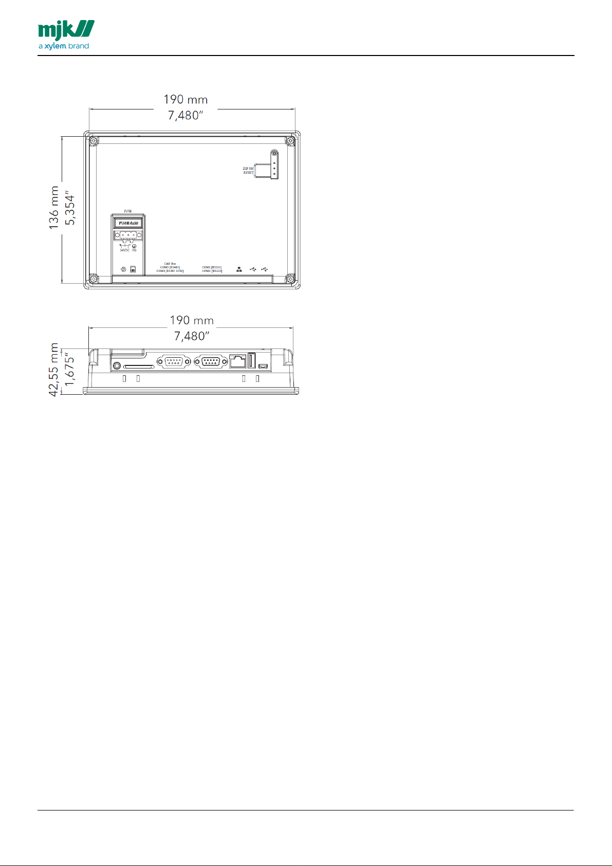
Dimensions
MANUAL
HMI display
7
Page 8
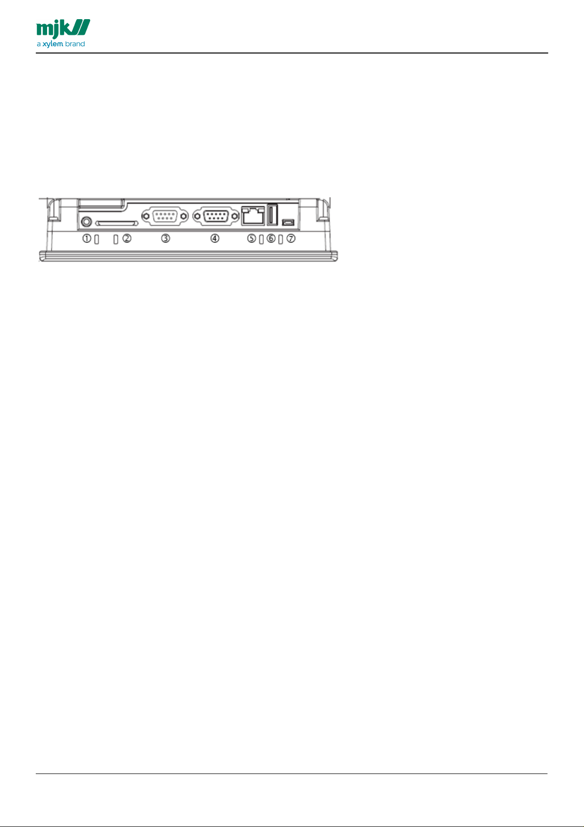
Electrical and mechanical mounting and connecting
The HMI display provides the following connection options:
1. Audio Line Out - 3.5 mm jack
2. SD Card Slot SDHC
3. COM1 RS-232 2W/4W
4. COM3 RS-485 2W Supports MPI 187.5K
5. Ethernet Port 10/100 Base-T
6. USB Host USB 2.0
7. USB Client USB 2.0
MANUAL
HMI display
8
Page 9
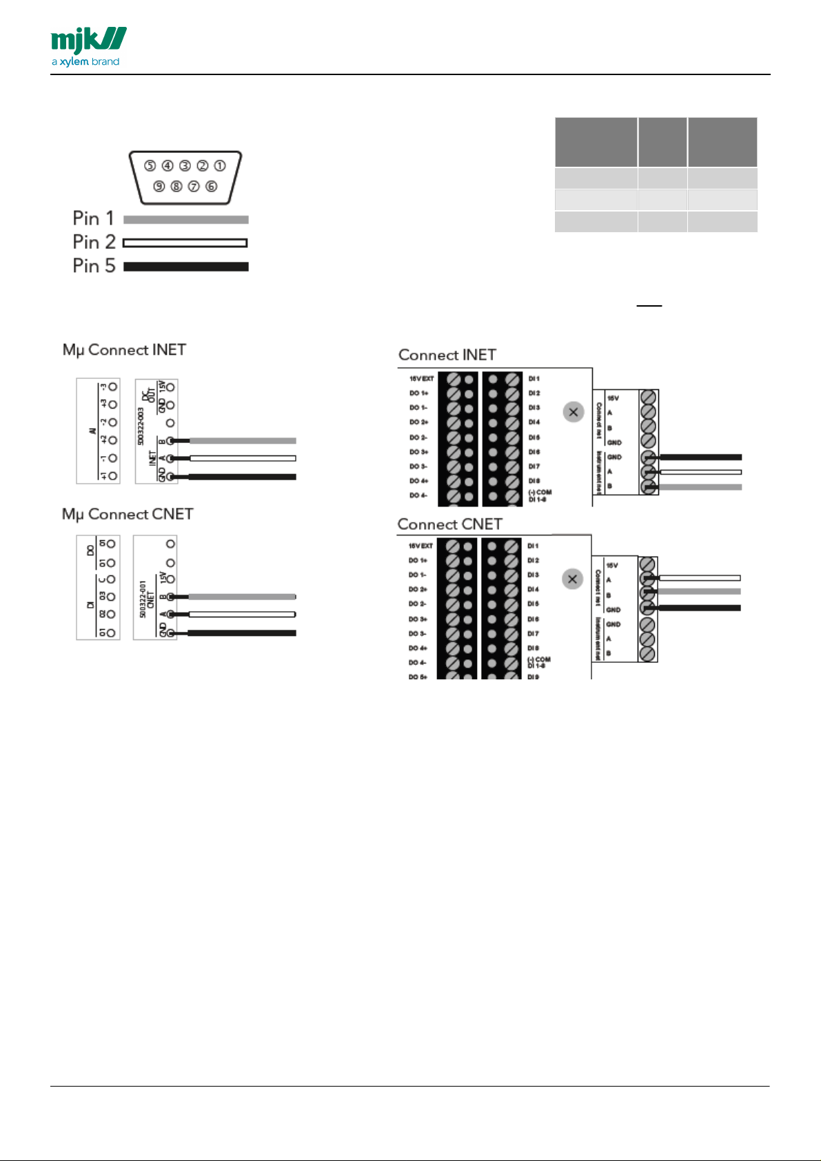
MANUAL
HMI C om 3 RS485
Port pin
9 Pin D-Sub
Female
Signal
Wire
color
1
B
Grey2A
White
5
GND
Black
Connecting to Mµ Connect device
Connecting to Connect device
HMI display
Mµ Connect / Connect RS485 CNET & INET
When the HMI display is connected using INET it cannot be used by additional units at an denne ikke bruges af andre
enheder simoultaneously.
9
Page 10
The shown configuration for INET is for M µ Connect udevice, m ade in Connect Link
MANUAL
HMI display
10
Page 11
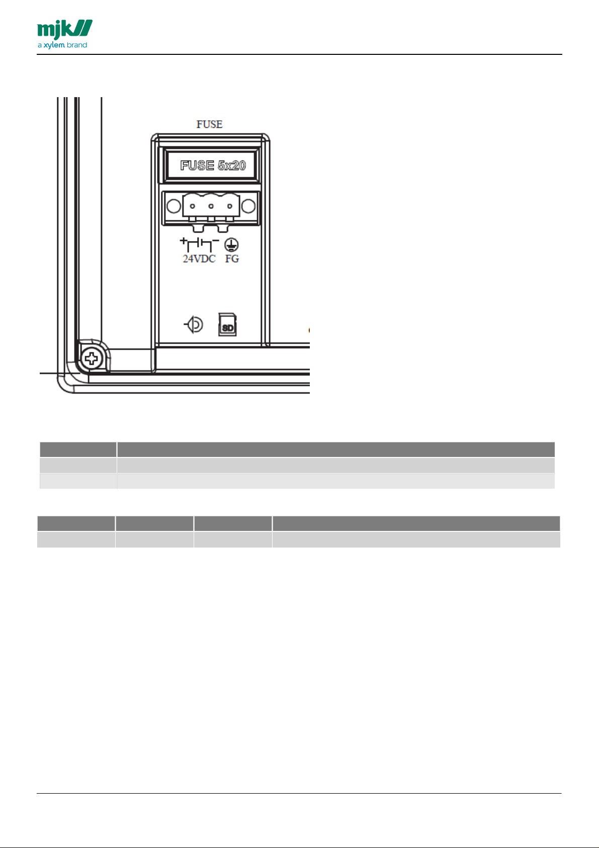
Power Supply
Terminal
Function
-
24 VDC minus
+
24 VDC plus
Power
Ampere
Order no.
Package
250 V
F 1,25A
5 x 20 mm
The HMI Display must be supplied with 24 VDC, Min. 400 mA
MANUAL
HMI display
Power Supply - 24 VDC
Internal Fuse
11
Page 12
Menu Screens and Operation
The following pages will describes details regarding the individual sub menus and statuses.
The main screen is created to provide most necessary information when arriving to a pump station.
Besides the top bar and clock/date, the screen provides the pumpscreen, including easy readable information on the
capacity for the station, fro the individual pumps and the level of the well.
If the screen is black, press anywhere on the touchscreen to activate.
This chapter describes the individual overview screens and menus in the HMI Display.
HMI display provides 6 primary screens.
Pumps
MANUAL
HMI display
12
Page 13
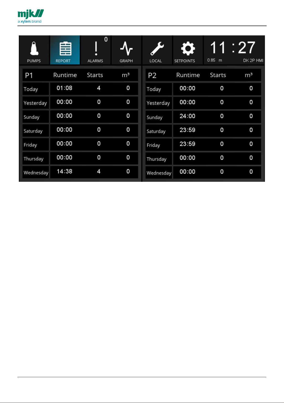
Report
The Report screen provides an overview of the capacity per pump, per day, making a simple evaluation of the
configuration the past week.
MANUAL
HMI display
13
Page 14
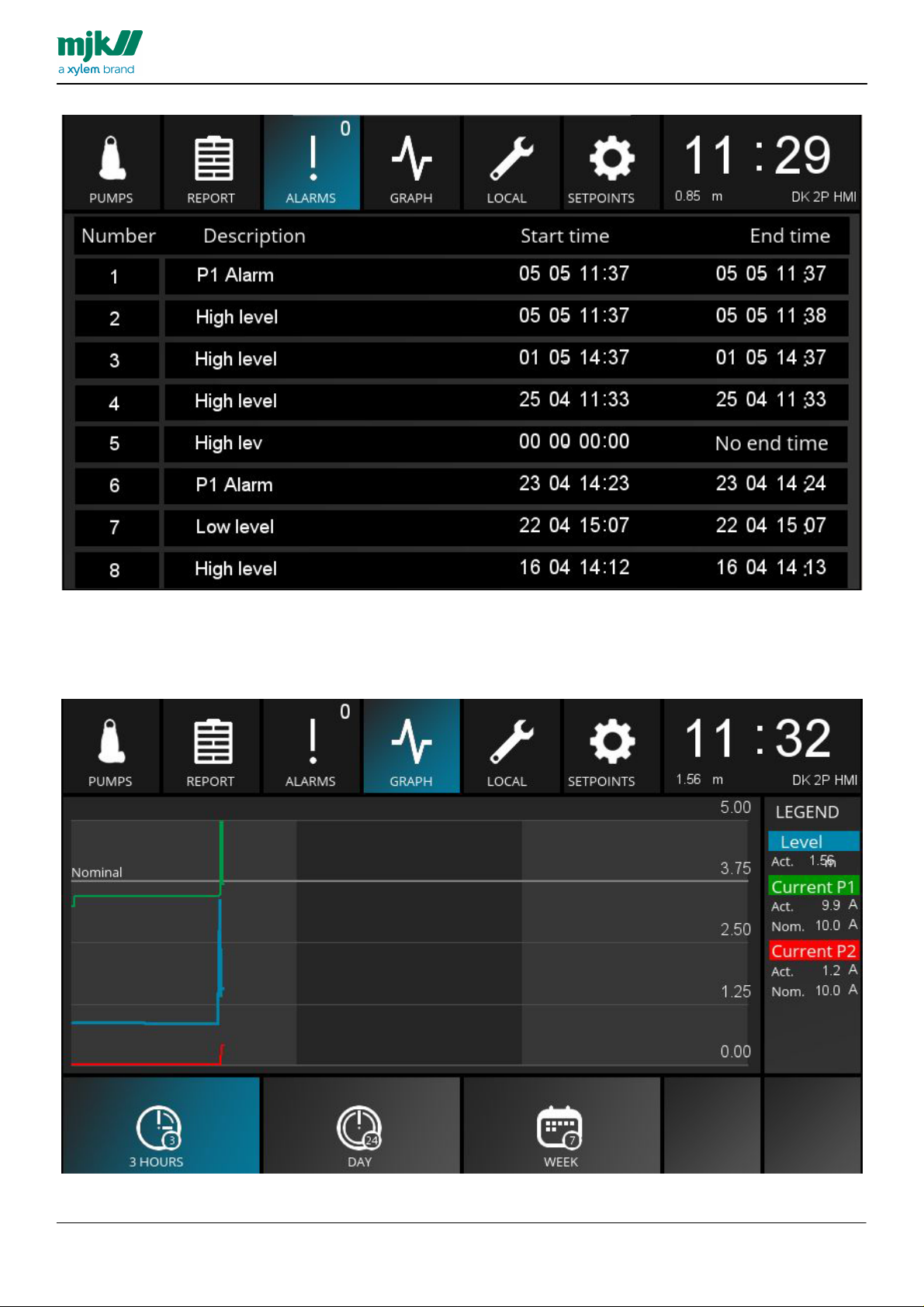
Alarms
The Alarm screen provides a list of the 8 most recent alarms from the station, including information in regards of the
state of the individual alarm.
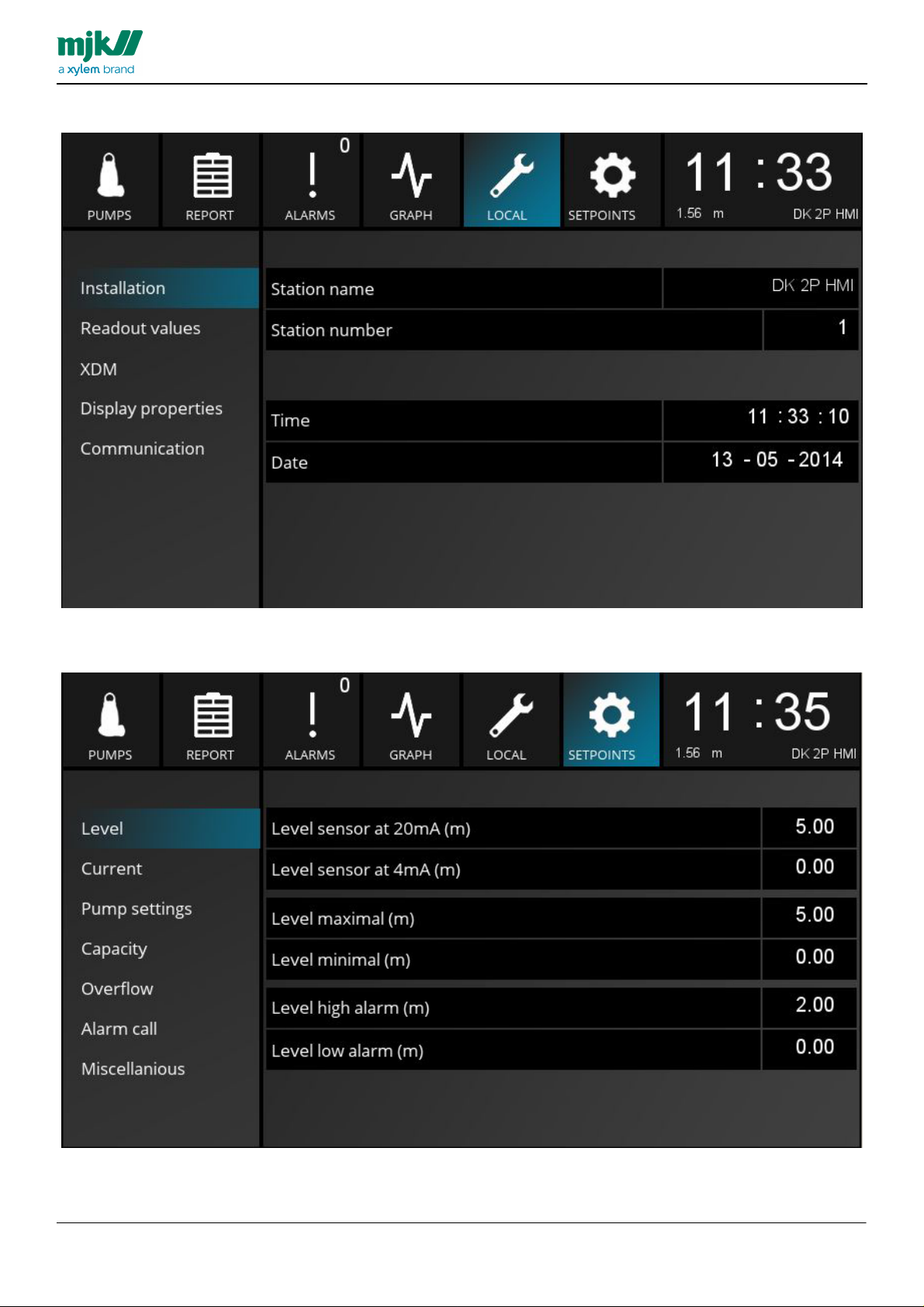
The Graph screen provides a graphical view of the level of the well, as well as the power consumtion per pump..
MANUAL
HMI display
Graph
14
Page 15
Local
The Local screen allows access to information and configuration of the station.
The Setpoint screen allows configuration of the functions of the HMI display includuing start/stop levels of station
and much more.
MANUAL
HMI display
Setpoints
15
Page 16

Prerequisites
Analog Input
Signal Name
Scaling 4mA
Scaling 20mA
Device - type
units
Averaging
AI 1
Level
0
Depending on
the connected
device
Level
m, 2 decimals
0 sec.
AI 2
Power P1
0
Depending on
the connected
device
Other devices
A, 1 decimal
0 sec.
AI 3
Power P2
0
Depending on
the connected
device
Other devices
A, 1 decimal
0 sec.
Digital output
Signal Name
Relay function
Closing time
Seconds on
time
Delay
DO 1
Start / stop P1
NO- constant
0 sec.
0 sec.
DO 2
Start / stop P2
NO- constant
0 sec.
0 sec.
Virtual analog input
Signal Name
High Alarm
Low Alarm
VAI 3
Power P1 (Illustrated in
HMI)
In use, Yes
In use, Yes
This VAI is used for
Setpoint for upper
and lower limits in the
main screen ampere
view.
VAI 4
Power P2 (Illustrated
in HMI)
In use, Yes
In use, Yes
This VAI is used for
Setpoint for upper
and lower limits in the
main screen ampere
view.
The HMI configuration is created for operating the MJK Mµ Connect Pump Control 1 using control words.
Mµ Connect device must have firmware version 844008-013.
This FW contains e.g. 7 days history.
Control word in Pump control 1 must be activated.
The following I/O is permanently connected:
MANUAL
HMI display
Additional I/O can be wired
Besides this the following can be created:
16
Page 17

MANUAL
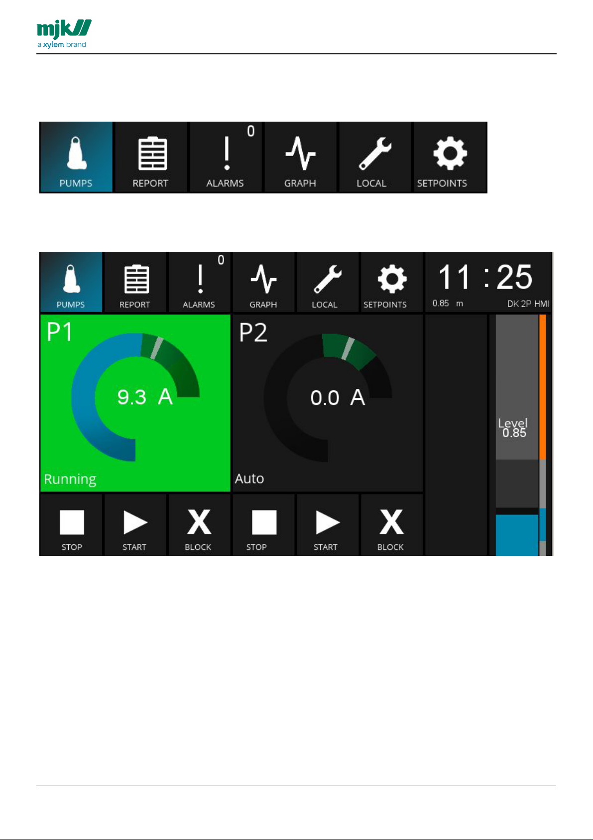
The screen is divided in various elements described on the following pages.
HMI display
Pumps, overview screen
Pumps screen
This screen also serves as start screen, shows the status of the pumps and provides control of the pumps and options
of resetting alarms.
17
Page 18

Pump element
When selecting this element a detailed screen for the individual pump is shown,
this screen provides the following options and informations:
MANUAL
HMI display
Pump element device window
The individual elements is shown on the following pages:
18
Page 19

Pump element
Menu Item
Text
Defaul
t
Description
Background
color
The color of the background in this element will switch depending on the
operating condition of the pump.
The colors are similar to the colors used in most SCADA systems.
Pump operating
condition
Stopped
Grey
The pump is stopped
Pump operating
condition
Not
operating
Black
The pump is blocked
Pump operating
condition
Operating
green
The pump active (operating),
Pump operating
condition
Error
red
Error on the pump
Pump operating
condition
Blocked
Blue
The pump is blocked
Ampere meter
Blue
Orang
e
The Ampere meter illustrates the actual power consumption of the pump.
the green area is illustrating the safe range of 10% -/+ of the nominal current. This is
creating a simple visualization of the power consumption being acceptable.
If the acceptable range is exeeded the color will change from green to orange.
The grey line illustrates the acceptable range of nominal current, this value is
entered in SETPOINTS>Current
This will make it easy to evaluate if the actual power consumption is proportional to
the nominal current of the individual pump.
Ampere
numerical
Illustration
A
Numerical Ampere value of the powerconsumption of the individual pump.
Menu Item
Description
Stop
Stop the pump.
Start
Start the pump
Block
Block the pump. Press start to restart the pump.
When the pump is blocked, no alarms will be activated from the device to the SCADA system
MANUAL
HMI display
Betjeningsknapper
19
Page 20

Operating data
Menu Item
Description
Runtime
Runtime today, yesterday, since last service and in total
Last service value can be reset in LOCAL>Readout values
Starts
Number of starts today, yesterday, after service and totals.
m3
The pumped volume today, yesterday and totals.
Menu Item
Valg
Default
Description
Alarm reset
Reset alarm button.
When pressing the button the active alarms will be reset.
MANUAL
HMI display
Reset Alarm
20
Page 21

Level Element
Menu Item
Description
The Level element works as a shortcut to SETPOINTS>Pump Settings, in which e.g. the start/
stop levels can be adjusted.
Level,
Left area
The left bar illustrates the actual level of the well.
If the level is acceptable the color will blue.
If the level is below minimum requirements or above acceptable level the color will switch to orange
Level,
Right Area
The start/stop levels AND the high/low alarm limits is illustrated in this bar.
Orange illustrates the high/low alarm levels.
Grey illustrates the start and stop levels.
Blue illustrates the acceptable levels.
MANUAL
HMI display
21
Page 22

Report
Menupunkt
Beskrivelse
Days
7 days is shown
Runtime
Runtime for the pumps in hours and minutes on the day
Starts
Number of starts per pump per day
m3
Pumped volume per pump per day.
The Report screen provides an overview of the operatiion of the pumps the past 7 days.
MANUAL
HMI display
22
Page 23

Alarms
Menu Item
Description
Number
Order of the 8 most recent alarms
Description
Description of the type of alarm occured and text as Defined from I/O device
Start time
Start time of the alarm, if the alarm occured more than 24 hours ago, th edate will be shown as well
End time
End time of the alarm (if ended). if the alarm has ended more than 24 hours ago, the date will be
shown as well.
This screen provides an overview of the 8 most recent alarms
MANUAL
HMI display
23
Page 24

Graph
Menu Item
Description
Graphs
Visual illustration of the level and power consumption per pump during a selected period.
The figures on the right side of the graph indicates a scaling of the level based on minimum and
maximum scaling of the level and current measurement.
The second graph (from the top), is the nominal value for the pumps. Hereby scaling their graphical
value.
Nominal graph
The nominal Graph is grey.
When a pump reaches its nominal current the graph will be on this line.
Alle pumper skaleres op mod denne linje. Derfor vises der alligevel grafer for pumper som kører med
forskellige nominalstrømme. Hermed undgår man at pumper med stærk afvigende nominalstrømme
falder væk fra denne graf.
Menu Item
Default
Description
Numeric indication of the values shown in the graph window
Level
Blue
Level value; the actual level of the well.
Current P1
Green
Current value Pump 1, actual value and nominal value.
Current P2
Red
Current value Pump 2, actual value and nominal value.
Menu Item
Description
3 Hours
Time span of 3 hours
Day
Time span of 24 hours
Week
Time span of one week
This screen provides a graphical illustration of the power consumption during selected periods.
MANUAL
HMI display
Legend
Time span selection
24
Page 25

Local
Navigation Menu, left
Installation
Configuration of the station.
Readout values
Reset button regarding runtime and starts after service and overflow
volume.
XDM
Stores information of the data of the pump.
Display Properties
Select display language and more.
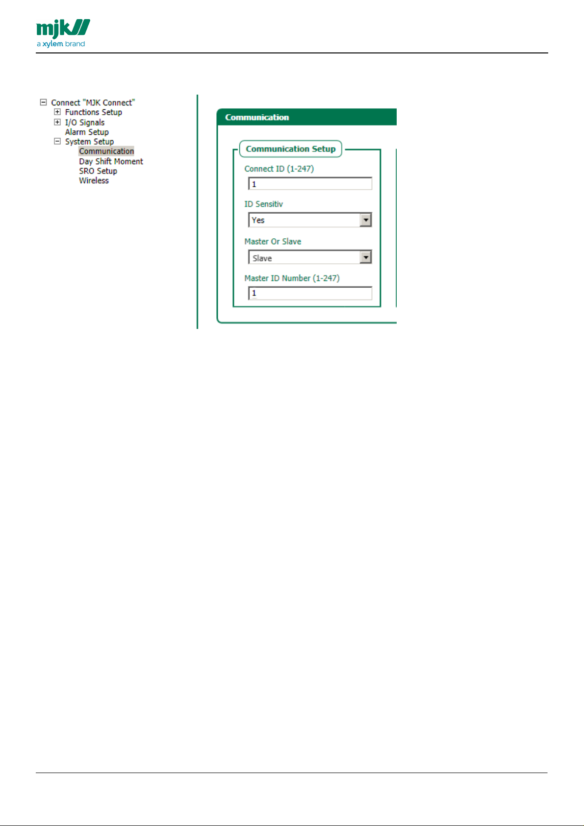
Communication
Adjust modem configuration and VNC.
Setup options in regards to the station configuration.
MANUAL
HMI display
Local screen contains 5 submenus.
25
Page 26

Installation
Menu Item
Options
Default
Description
Station Name
Name of the station, this name will be shown beneith the clock.
Station Number
1-247
Station number (ID number in the SCADA system). This will also be shown beneith
the clock.
Time
hh:mm:
ss
Adjust the clock.
Date
ddmmyyyy
Adjust the date.
MANUAL
HMI display
26
Page 27

Readout Values
Menu Item
Opti
ons
Default
Description
P1 Runtime
since last
service (h)
Reset P1 runtime since last service (shown in pump element)
P1 Starts since
last service
Reset P1 number of starts since last service (shown in pump element)
P2 Runtime
since last service
(h)
Reset P2 runtime since last service (shown in pump element)
P2 Starts since
last service
Reset P2 number of starts since last service (shown in pump element)
Starts, Reset
button
This will reset number of starts since service.
Starts, numeric
column
Number of starts since service can be adjusted in this column
Overflow
Overflow
volume today
Overflow volume m3.
Overløbsvolum
e yesterday
Overflow volume m3.
Counter
24-hour
counter actual
value
Actual value of 24 hour counter.
MANUAL
HMI display
27
Page 28

XDM
Menu Item
Options
Default
Description
Pump type
Enter type of pump.
Impeller
Enter type of impeller.
kW
Enter kW for pump.
Nominal current
Nominal current for pump
Production year
Pump production year
Serial number
Pump serial number
Informations regarding the connected pumps
MANUAL
HMI display
28
Page 29

Display Properties
Menu Item
Options
Default
Description
Language
English
Italian
Spanish
German
French
Swedish
Finnish
Portuguese
Norwegian
Danish
Danish
Choose language from the drop-down menu.
Brightness
Adjust by pressing + or -.
CPU load
display
Actual CPU load of the display.
Free space
display
Free space on the Display memory
MANUAL
HMI display
29
Page 30

Communication
Menu Item
Options
Default
Description
Connection
status
Current status on the modem connection.
IP address SIM
card
Shows IP address provided by SIM card in modem.
Connection
strength CSQ
GSM/GPRS strength of connection.
Local – communication 1
Use the up/down arrows to switch between addtional communication screens
MANUAL
HMI display
30
Page 31
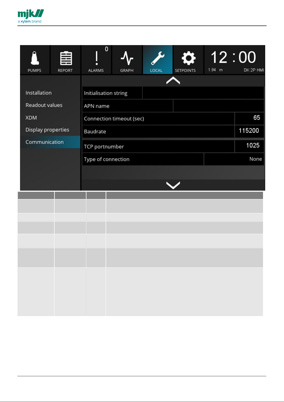
Local – Communication 2
Menu Item
Options
Default
Description
Initiation string
Modem
Select to
adjust
Initiation string for modem.
APN name
Name of access point.
Connection
Timeout
0-9999 sec
15
Connection timeout in seconds. Press to adjust the value.
Baudrate
115200
Baud rate in the modem. Baud rate is the number of bits strasnferred per
second. Press to adjust the value.
TCP
portnumber
1025
TCP port number in the modem. This port number is used to establish TCP
connection. Press to adjust the port number.
This number is only used for TCP connections.
Type of
connection
None
TP6000
NIROS
RS232
RS485 no
termination
RS485 with
termination
None
MANUAL
HMI display
31
Page 32

Local – Communication 3
Menu Item
Options
Default
Description
HMI IP address
Select to
adjust
IP address of the HMI Display.
This address is used when creating a VNC Connection from the HMI Display.
HMI ethernet
mask
Select to
adjust
HMI Display Ethernet mask.
HMI ethernet
gateway
address
Select to
adjust
HMI Display Ethernet gateway address.
HMI ethernet
port
Select to
adjust
HMI Display Ethernet port. This port is used to connect to the HMI Display.
VNC server
Turn on/off the VNC server.
When turned off, the HMI Display cannot be accessed remotely
Multiple VNC
Connection
Allow multiple VNC connections. When this is on, multiple devices cannot be
accessed remotely.
VNC password
Select to
adjust
Adjust the access code for VNC server. This code is only used when
accessing remotely
MANUAL
HMI display
32
Page 33

Setpoints
Navigation Menu, Left
Level
Current
Pump Settings
Capacity
Overflow
Alarm Call
Miscellaneous
MANUAL
HMI display
Setpoint screen provides 7 submenus.
33
Page 34

Level
Menu Item
Option
Default
Description
Level sensor at
20 mA
-99 - 999
Depen
ding on
sensor
Adjust level hight when level sensor provides 20 mA. Select to adjust.
Level sensor at
4 mA
-99 - 999
Depen
ding on
sensor
Adjust level hight when level sensor provides 4 mA. Select to adjust.
Level maximal
-99 - 999
Depen
ding on
sensor
Adjust setpoint limitation in relation to max level. Select to adjust.
Level minimal
-99 - 999
Depen
ding on
sensor
Adjust setpoint limitation in relation to max level. Select to adjust.
Level high alarm
Select to
adjust
Set level for high alarm
Level low alarm
Select to
adjust
Set level for high alarm
MANUAL
HMI display
34
Page 35

Current
Menu Item
Option
Default
Description
P1 range current
measurement
0-9999 A
Depending
on
configuration
Adjust measuring range for current in ampere. The figure is the max value
for the pumps. Select to adjust.
P1 high current
0-9999 A
Depending
on
configuration
Adjust high current alarm value in ampere. select to adjust.
P1 low current
0-9999 A
Depending
on
configuration
Adjust low current alarm value in ampere. Select to adjust.
P1 nominal
current
0-9999 A
Depending
on
configuration
Adjust normal current value in ampere. Select to adjust.
MANUAL
HMI display
35
Page 36

Current - 2
MANUAL
HMI display
sam e settings on P2
36
Page 37

Pump configuration
Menu Item
Option
Default
Description
Number of
pumps
0-2
Depending on
configuration
Number of pumps connected in this installation. Depending on the
configuration used, it is possible to configure 1-2 or 3-4 pumps. This value
decided the number of pumps viewed in the display. Select to adjust.
Pumps
simultaneously
0-2
Depending on
configuration
The number of simultaneously running pumps allowed. Select to adjust.
Start level 1
Select to
adjust
The first start level for the pumps.
Stop level 1
Select to
adjust
The first stop level for the pumps.
Start level 2
Select to
adjust
The second start level for the pumps.
Stop level 2
Select to
adjust
The second stop level for the pumps.
MANUAL
HMI display
37
Page 38

Pump configuration - 2
Menu Item
Option
Default
Description
P1 Alternation
On / Off
Depending on
configuration
Activate or de-activate pump alternation.
Select to adjust
P1 Maximum
runtime
0-9999
(Sec)
0
Maximum runtime for the pump in seconds. When the value is exceeded,
the station will send an alarm. Select to adjust.
P1 start delay
0-9999
(Sec)
0
Delay in seconds. Select to adjust.
Same for P2
MANUAL
HMI display
38
Page 39

Pump configuration - 3
Menu Item
Option
Default
Description
Dynamic level offset
Select to
adjust
0,00
Level setpoint displacement.
Dynamic level start
time
hh:mm
00:00
Start time for setpoint displacement in hours and minutes. Select to
adjust.
Dynamic level stop
time
hh:mm
00:00
Stop time for setpoint displacement in hours and minutes. Select to
adjust.
Periodic pumping
by P1/P2
OFF/P1/
P2
OFF
Select the pump for periodic depth pumping. Select to adjust.
Periodic pumping
time
Select to
adjust
0
Adjust runtime (in seconds) for periodic depth pumping.
Periodic pump
(every xx starts)
Select to
adjust
0
Number of starts between periodic depth pumping.
MANUAL
HMI display
Delay of high-level signal (float-switch)
The delay is specified in seconds. Select to adjust.
39
Page 40

Capacity
Menu Item
Option
Default
Description
Start level
capacity
measurement
Select to
adjust
Enter start level
Stop level
capacity
measurement
Select to
adjust
Enter stop level
Volume capacity
reading
Select to
adjust
Enter volume between start/stop level for capacity measurement
MANUAL
HMI display
40
Page 41

Overflow
Menu Item
Option
Default
Description
Overflow
level 1
0,00 - 10,00 m
0,00
Overflow level in meters. Select to adjust
Overflow
capacity 1
0,0 - 9999,99 m3/h
0,0
Overflow capacity in m3/h. Select to adjust
MANUAL
HMI display
41
Page 42

Alarm call
Menu Item
Option
Default
Description
Call type
0-4
0 - None
1 - PC (Scada)
2 - Telefon
3 - SMS
4 - GPRS
Phone number 1
Select to
adjust
Enter the number for the connection. This is relevant
This is relevant after selecting type in "Call type". This phone number is the
number that will receive the information*/data shipped from the HMI display.
Time between
calls
0-9999
(Min)
0
Adjust time, in minutes, between calls
Menu Item
Option
Default
Description
Station name
Select to
adjust
Station number
Select to
adjust
(ID no.)
Setup – Alarm call 1
MANUAL
HMI display
42
Page 43

Setup – Alarmopkald 2
Menu Item
Valg
Default
Description
Alarm delay high
level
0-9999
(sec)
0
Enter number of seconds before sending high alarm.
Alarm delay low
level
0-9999
(sec)
60
Enter number of seconds before sending low alarm.
MANUAL
HMI display
43
Page 44

Miscellaneous
Menu Item
Valg
Default
Description
Test alarm
On / Off
Start time for
test alarm
(hh:mm)
00:00
Time of day in hours and minutes
24-hour counter
alarmvalue
Select to
adjust
Alarm value for 24-hours counter.
Person on site
detection delay
Select to
adjust
Delay in seconds - when the panel is opened, the value is the number of seconds
before sending the alarm to the scada.
Person on site
alarm
On / Off
Off
See is a person on sie alarm is active or off. If active, this button can turn off the
alarm.
trend resolution
(sec)
30-3600
Seconds
30
Adjust the extended datalogger logging interval.
MANUAL
HMI display
44
Page 45

Clock element.
Press the clock to read state of the connected Mµ Connect I/O.
MANUAL
HMI display
45
Page 46

Status I/O signals
MANUAL
HMI display
Digital in/out
46
Page 47

1) The tissue in plants that brings water upward from the roots;
2) a leading global water technology company.
We’re 12,000 people unified in a common purpose: creating innovative solutions
to meet our world’s water needs. Developing new technologies that will improve
the way water is used, conserved, and re-used in the future is central to our work.
We move, treat, analyze, and return water to the environment, and we help people
use water efficiently, in their homes, buildings, factories and farms. In more than
150 countries, we have strong, long-standing relationships with customers who
know us for our powerful combination of leading product brands and applications
expertise, backed by a legacy of innovation.
For more information on how Xylem can help you, go to www.xyleminc.com
MJK Automation A/S
Byageren 7
DK-2850 Nærum
Denmark
Tel +45 45 56 06 56
Fax +45 45 56 06 46
www.mjk.com
Connect, MµConnect, Chatter, MagFlux, Oxix, pHix compact, Shuttle and
SuSix
are registrered trademarks of MJK Automation A/S.
© 2013 Xylem, Inc.
 Loading...