

Page 1
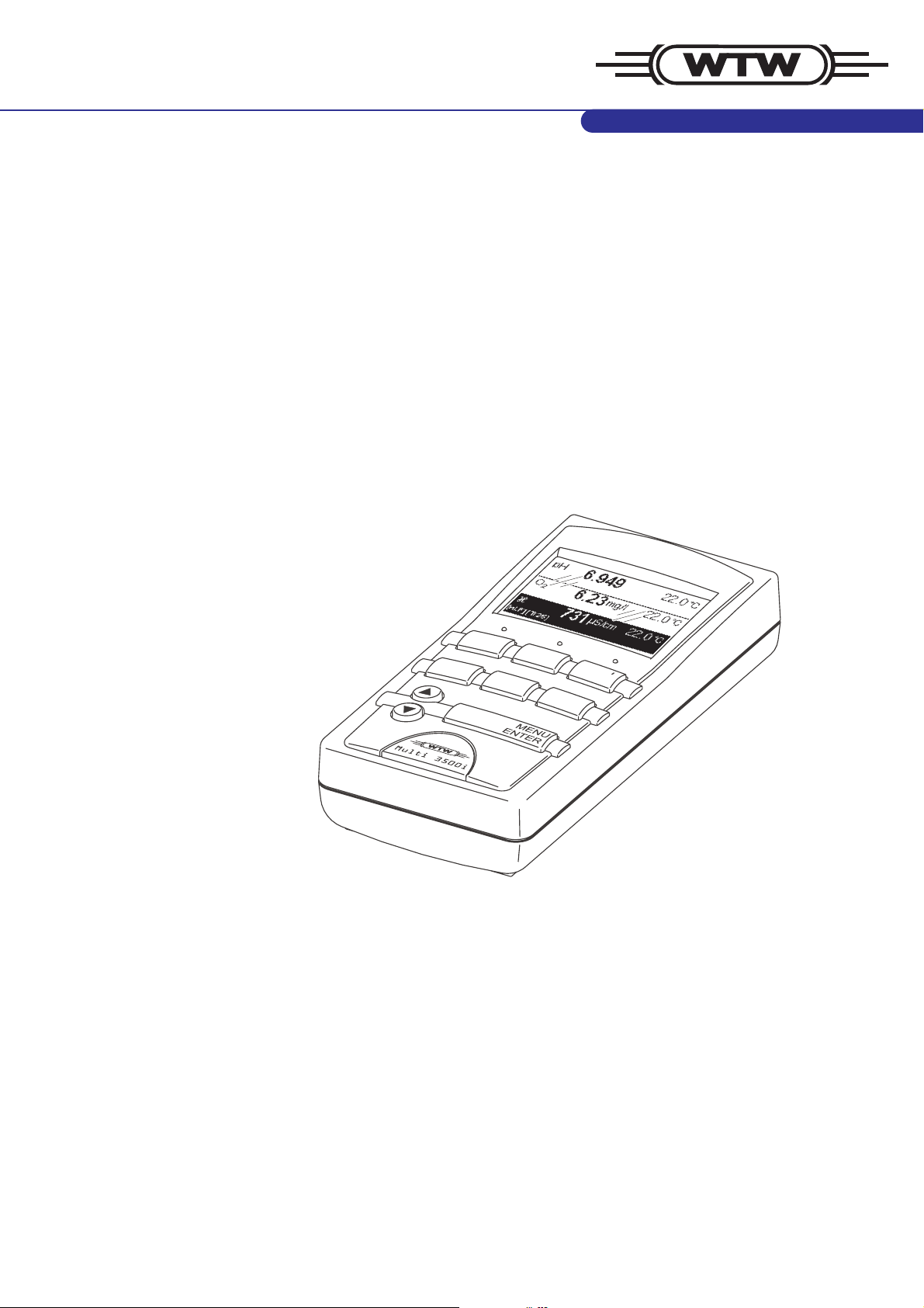
Multi 3500i
Operating manual
M
C
AL
STO
P
R
T
O
ESC
pH / ISE / DO / conductivity measuring instrument
ba75689e01 01/2007
Page 2

Accuracy when
going to press
Currentness of firmware The process of consistently improving our products includes the
The use of advanced technology and the high quality standard of our
instruments are the result of a continuous development. This may
result in differences between this operating manual and your
instrument. Also, we cannot guarantee that there are absolutely no
errors in this manual. Therefore, we are sure you will understand that
we cannot accept any legal claims resulting from the data, figures or
descriptions.
continuous further development of instrument firmware. The current
Multi 3500i firmware is available on the Internet. It can easily be
downloaded on your meter using the enclosed AK 340/B cable and a
PC. For more detailed information, refer to the appendix of this
operating manual or to the Internet under http://www.WTW.com
.
Copyright
© Weilheim 2007, WTW GmbH
Reproduction in whole - or even in part - is prohibited without the
express written permission of WTW GmbH, Weilheim.
Printed in Germany.
Page 3

Multi 3500i Contents
1 Overview . . . . . . . . . . . . . . . . . . . . . . . . . . . . . . . . . . . . . . 3
1.1 General features . . . . . . . . . . . . . . . . . . . . . . . . . . . . . . . 3
1.2 SETs of equipment . . . . . . . . . . . . . . . . . . . . . . . . . . . . . . 4
1.3 Keypad . . . . . . . . . . . . . . . . . . . . . . . . . . . . . . . . . . . . . . . 6
1.4 Display . . . . . . . . . . . . . . . . . . . . . . . . . . . . . . . . . . . . . . . 7
1.5 Socket field . . . . . . . . . . . . . . . . . . . . . . . . . . . . . . . . . . . . 7
2 Safety . . . . . . . . . . . . . . . . . . . . . . . . . . . . . . . . . . . . . . . . 9
2.1 Authorized use . . . . . . . . . . . . . . . . . . . . . . . . . . . . . . . . . 9
2.2 General safety instructions . . . . . . . . . . . . . . . . . . . . . . . 10
3 Commissioning . . . . . . . . . . . . . . . . . . . . . . . . . . . . . . . 11
3.1 Scope of delivery . . . . . . . . . . . . . . . . . . . . . . . . . . . . . . 11
3.2 Power supply . . . . . . . . . . . . . . . . . . . . . . . . . . . . . . . . . 11
3.3 Initial commissioning . . . . . . . . . . . . . . . . . . . . . . . . . . . 12
4 Operation . . . . . . . . . . . . . . . . . . . . . . . . . . . . . . . . . . . . 13
4.1 Switching on the measuring instrument . . . . . . . . . . . . . 13
4.2 General operating principles . . . . . . . . . . . . . . . . . . . . . 14
4.2.1 Operating modes . . . . . . . . . . . . . . . . . . . . . . . . 14
4.2.2 Navigation . . . . . . . . . . . . . . . . . . . . . . . . . . . . . 15
4.2.3 Example 1 on navigation: Setting the language 17
4.2.4 Example 2 on navigation: Setting the date and
time . . . . . . . . . . . . . . . . . . . . . . . . . . . . . . . 19
4.3 System settings (system menu) . . . . . . . . . . . . . . . . . . . 21
4.3.1 Data storage . . . . . . . . . . . . . . . . . . . . . . . . . . . 21
4.3.2 Display . . . . . . . . . . . . . . . . . . . . . . . . . . . . . . . 21
4.3.3 System . . . . . . . . . . . . . . . . . . . . . . . . . . . . . . . 23
4.4 pH value / ORP voltage . . . . . . . . . . . . . . . . . . . . . . . . . 25
4.4.1 General information . . . . . . . . . . . . . . . . . . . . . . 25
4.4.2 Measuring the pH value . . . . . . . . . . . . . . . . . . 27
4.4.3 Measuring the ORP voltage . . . . . . . . . . . . . . . 28
4.4.4 Settings for pH and ORP measurements . . . . . 29
4.4.5 pH calibration . . . . . . . . . . . . . . . . . . . . . . . . . . 30
4.4.6 Carrying out the TEC and NIST/DIN calibration 34
4.4.7 Carrying out a ConCal calibration . . . . . . . . . . . 38
4.5 Ion concentration . . . . . . . . . . . . . . . . . . . . . . . . . . . . . . 41
4.5.1 General information . . . . . . . . . . . . . . . . . . . . . . 41
4.5.2 Measuring the ion concentration . . . . . . . . . . . . 42
4.5.3 Settings for ISE measurements . . . . . . . . . . . . 43
4.5.4 Calibrating for ISE measurements . . . . . . . . . . 43
4.6 Dissolved oxygen . . . . . . . . . . . . . . . . . . . . . . . . . . . . . . 49
4.6.1 General information . . . . . . . . . . . . . . . . . . . . . . 49
4.6.2 Measuring . . . . . . . . . . . . . . . . . . . . . . . . . . . . . 50
4.6.3 Settings for DO sensors . . . . . . . . . . . . . . . . . . 51
4.6.4 DO calibration . . . . . . . . . . . . . . . . . . . . . . . . . . 53
1
Page 4

Contents Multi 3500i
4.7 Conductivity . . . . . . . . . . . . . . . . . . . . . . . . . . . . . . . . . . 58
4.7.1 General information . . . . . . . . . . . . . . . . . . . . . . 58
4.7.2 Measuring . . . . . . . . . . . . . . . . . . . . . . . . . . . . . 59
4.7.3 Temperature compensation . . . . . . . . . . . . . . . . 60
4.7.4 Settings for conductivity measuring cells . . . . . . 61
4.7.5 Determining the cell constant (calibration in the
control standard) . . . . . . . . . . . . . . . . . . . . . . . . 63
4.8 Data storage . . . . . . . . . . . . . . . . . . . . . . . . . . . . . . . . . . 66
4.8.1 Manual data storage . . . . . . . . . . . . . . . . . . . . . 67
4.8.2 Automatic data storage at intervals . . . . . . . . . . 68
4.8.3 Editing the measured value storage . . . . . . . . . 70
4.8.4 Erasing the measured value storage . . . . . . . . . 73
4.8.5 Displaying and outputting calibration records . . 74
4.9 Transmitting data (RS 232 interface) . . . . . . . . . . . . . . . 76
4.9.1 Options for data transmission . . . . . . . . . . . . . . 76
4.9.2 Connecting a PC/external printer . . . . . . . . . . . . 77
4.9.3 Operation with MultiLab pilot . . . . . . . . . . . . . . . 77
4.10 Reset . . . . . . . . . . . . . . . . . . . . . . . . . . . . . . . . . . . . . . . 78
4.10.1 Resetting the sensor settings . . . . . . . . . . . . . . 78
4.10.2 Resetting the system settings . . . . . . . . . . . . . . 79
5 Maintenance, cleaning, disposal . . . . . . . . . . . . . . . . .81
5.1 Maintenance . . . . . . . . . . . . . . . . . . . . . . . . . . . . . . . . . . 81
5.2 Cleaning . . . . . . . . . . . . . . . . . . . . . . . . . . . . . . . . . . . . . 81
5.3 Disposal . . . . . . . . . . . . . . . . . . . . . . . . . . . . . . . . . . . . . 81
6 What to do if... . . . . . . . . . . . . . . . . . . . . . . . . . . . . . . . . 83
6.1 pH and ORP measurement . . . . . . . . . . . . . . . . . . . . . . 83
6.2 ISE measurement . . . . . . . . . . . . . . . . . . . . . . . . . . . . . . 85
6.3 DO measurement . . . . . . . . . . . . . . . . . . . . . . . . . . . . . . 86
6.4 Conductivity measurement . . . . . . . . . . . . . . . . . . . . . . . 87
6.5 General errors . . . . . . . . . . . . . . . . . . . . . . . . . . . . . . . . . 88
7 Technical data . . . . . . . . . . . . . . . . . . . . . . . . . . . . . . . .89
7.1 General data . . . . . . . . . . . . . . . . . . . . . . . . . . . . . . . . . . 89
7.2 Measuring ranges, resolution, accuracy . . . . . . . . . . . . . 91
7.2.1 pH/ORP . . . . . . . . . . . . . . . . . . . . . . . . . . . . . . . 91
7.2.2 ISE . . . . . . . . . . . . . . . . . . . . . . . . . . . . . . . . . . . 91
7.2.3 Dissolved oxygen . . . . . . . . . . . . . . . . . . . . . . . . 92
7.2.4 Conductivity . . . . . . . . . . . . . . . . . . . . . . . . . . . . 93
8 Lists . . . . . . . . . . . . . . . . . . . . . . . . . . . . . . . . . . . . . . . . .95
9 Index . . . . . . . . . . . . . . . . . . . . . . . . . . . . . . . . . . . . . . .101
Appendix: Firmware Update . . . . . . . . . . . . . . . . . . . . . . .103
2
Page 5
Multi 3500i Overview
1Overview
1.1 General features
The Multi 3500i compact precision handheld meter enables you to carry out pH measurements, ISE measurements, dissolved oxygen (DO)
measurements and conductivity measurements quickly and reliably.
The Multi 3500i handheld meter provides the maximum degree of operating comfort, reliability and measuring certainty for all applications.
®
The proven MultiCal
cedures to determine/set up the cell constant support you in your work
with the meter. The special AutoRead function enables precise measurements.
and OxiCal® calibration procedures and the pro-
3
2
M
C
A
L
STO
P
R
T
O
ESC
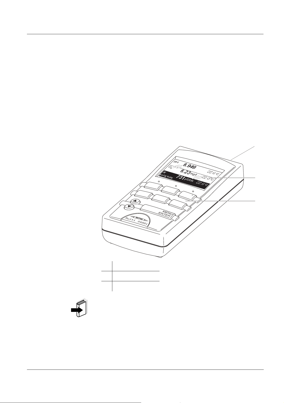
1
1 Keypad
2 Display
3 Socket field
Note
If you need further information or application notes, you can obtain the
following material from WTW:
z Application reports
z Primers
z Safety datasheets.
You will find information on available literature in the WTW catalog or
via the Internet.
3
Page 6
Overview Multi 3500i
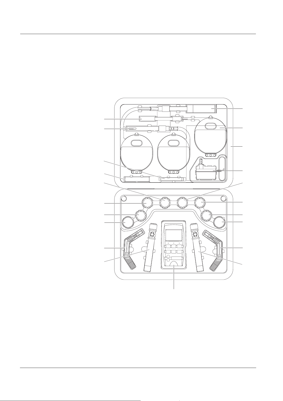
1.2 SETs of equipment
The measuring instrument is also available as part of individual SETs
of equipment.
You will find additional information on this and other accessories in the
WTW catalog or via the Internet.
16
15
14
13
12
10
11
17
18
19
9
8
7
6
5
4
2
5
4
3
1
4
Page 7

Multi 3500i Overview
Set (sample configuration):
1 Multi 3500i measuring instrument, carrying strap with 2 carrying
clips, armoring
2 Cond/Oxi beaker with beaker clip
3 pH beaker
4 Stand
5 Plastic beaker, 50 ml
6 Storing solution for pH electrodes
7 50 ml pH buffer solution, STP 4
8 50 ml pH buffer solution, STP 7
9 Calibration and control standard for conductivity measuring
cells, 50 ml
10 50 ml ELY/G electrolyte solution for DO sensors
11 50 ml RL/G cleaning solution for DO sensors
12 Exchange membrane caps for DO sensors (3 pieces)
13 SF 300 polishing strip for the maintenance of DO sensors
14 Conductivity measuring cell
15 pH combination electrode
16 DO sensor
17 Operating manual + short operating manual
18 Equipment case
19 Plug-in power supply unit
MultiLab pilot CD-ROM
5
Page 8
Overview Multi 3500i
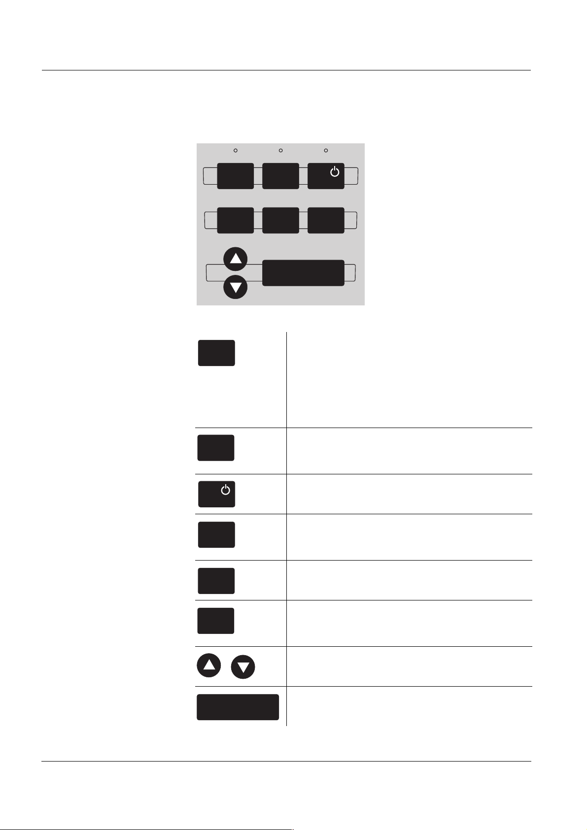
1.3 Keypad
PRTM
ESCSTOCAL
MENU
ENTER
Key functions
PRT
CAL
STO
ESC
M
Select the measured variable <M>:
– pH value / ORP / ion concentration
– DO concentration / DO saturation / DO partial
pressure
– Conductivity / specific resistance / salinity /
TDS
Output display contents to RS232 interface (e.g.
print)
<PRT>
Switch the measuring instrument on/off
<ON/OFF>
Calibrate the currently selected measured vari-
able
<CAL>
Store a measured value
<STO>
Switch to the next higher menu level /
cancel input
<ESC>
Set values
<▲>, <▼>
MENU
ENTER
6
Open a menu / confirm input
<MENU/ENTER>
Page 9
Multi 3500i Overview
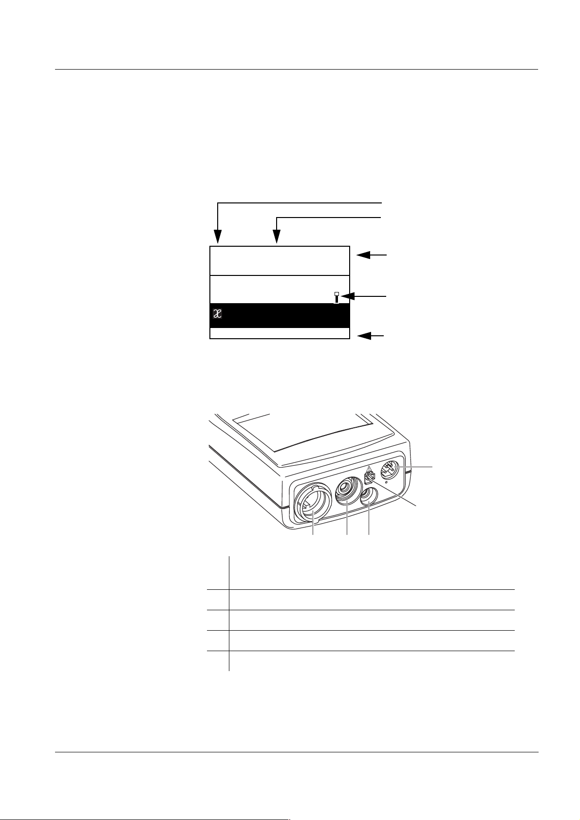
1.4 Display
The graphical display can indicate up to three measuring windows at
the same time. The illumination enables to read the display even in the
darkness. You can modify the display to meet your requirements in
multiple ways.
Measured variable
Measured value (with unit)
pH
O
2
[SAL]
[nLF][Tr25]
6.949
7.29
731
mg/l
µS/cm
05.09.03 09:25
1.5 Socket field
24.0
24.0
24.0
°C
°C
°C
Temperature display
Sensor symbol
Status line
5
4
123
1 DO sensor or conductivity measuring cell or combined con-
ductivity / DO sensor
2 pH electrode or ISE combination electrode
3 pH temperature sensor
4 Plug-in power supply unit
5 RS232 serial interface
7
Page 10

Overview Multi 3500i
8
Page 11
Multi 3500i Safety
2 Safety
This operating manual contains basic instructions that you must follow
during the commissioning, operation and maintenance of the measuring instrument. Consequently, all responsible personnel must read this
operating manual before working with the measuring system. The operating manual must always be available within the vicinity of the measuring system.
Target group The measuring instrument was developed for work in the field and in
the laboratory.
Thus, we assume that, as a result of their professional training and experience, the operators will know the necessary safety precautions to
take when handling chemicals.
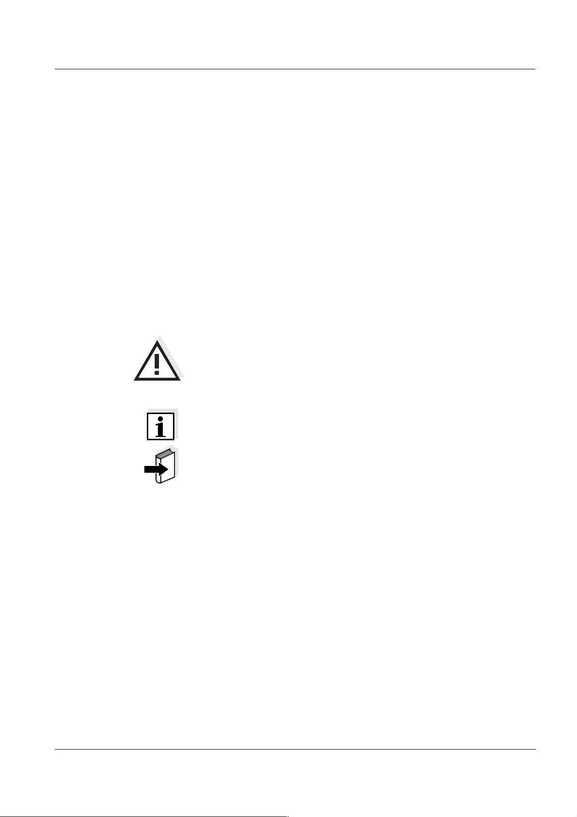
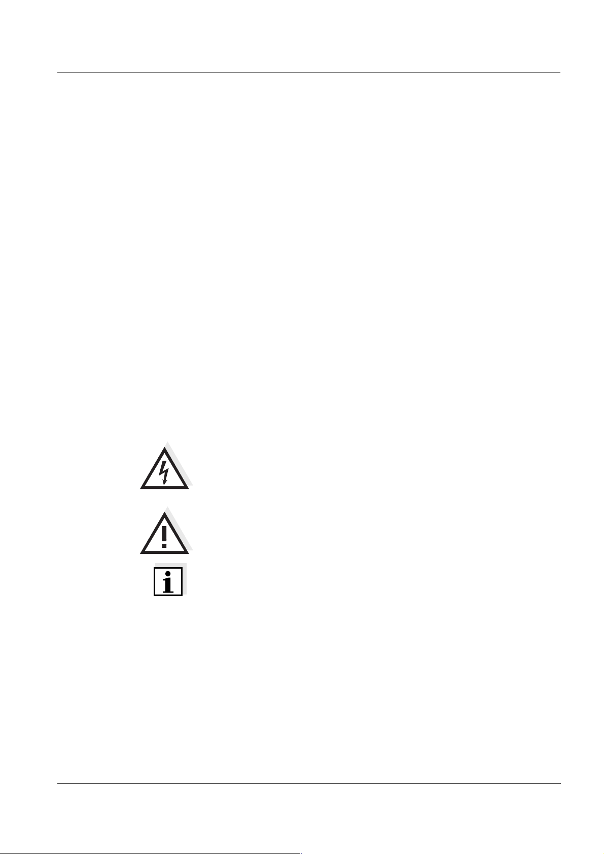
Safety instructions The individual chapters of this operating manual use the following safe-
ty instruction to indicate various types of danger:
Caution
indicates instructions that must be followed precisely in order to
avoid the possibility of slight injuries or damage to the instrument
or the environment.
Further notes
Note
indicates notes that draw your attention to special features.
Note
indicates cross-references to other documents, e.g. operating manuals.
2.1 Authorized use
The authorized use of the measuring instrument consists exclusively of
the:
z pH and ORP measurement
z ISE measurement
z measurement of dissolved oxygen (DO) and
z conductivity measurement
in the field and laboratory.
The technical specifications as given in chapter 7 T
be observed. Only the operation and running of the measuring instrument according to the instructions given in this operating manual is authorized. Any other use is considered to be unauthorized.
ECHNICAL DATA must
9
Page 12

Safety Multi 3500i
2.2 General safety instructions
This instrument is built and inspected according to the relevant guidelines and norms for electronic measuring instruments (see chapter
7T
ECHNICAL DATA).
It left the factory in a safe and secure technical condition.
Function and operating
safety
Safe operation If safe operation is no longer possible, the instrument must be taken out
The smooth functioning and operational safety of the measuring instrument can only be guaranteed if the generally applicable safety measures and the specific safety instructions in this operating manual are
followed during operation.
The smooth functioning and operational safety of the measuring instrument can only be guaranteed under the environmental conditions that
are specified in chapter 7 T
ECHNICAL DATA.
If the instrument was transported from a cold environment to a warm
environment, the formation of condensate can lead to the faulty functioning of the instrument. In this event, wait until the temperature of the
instrument reaches room temperature before putting the instrument
back into operation.
of service and secured against inadvertent operation!
Safe operation is no longer possible if the measuring instrument:
z has been damaged in transport
z has been stored under adverse conditions for a lengthy period of
time
Obligations of the
purchaser
z is visibly damaged
z no longer operates as described in this manual.
If you are in any doubt, please contact the supplier of the instrument.
The purchaser of this measuring instrument must ensure that the following laws and guidelines are observed when using dangerous substances:
z EEC directives for protective labor legislation
z National protective labor legislation
z Safety regulations
z Safety datasheets of the chemical manufacturers.
10
Page 13
Multi 3500i Commissioning
3 Commissioning
3.1 Scope of delivery
z Multi 3500i handheld measuring instrument with 4 rechargeable bat-
teries, 1.2 V type AA in the instrument
z Plug-in power supply with Euro plug,
exchange plugs for USA, UK, and Australia are enclosed
z Operating manual and short operating manual
z MultiLab pilot CD-ROM
3.2 Power supply
Mains operation and
charging the batteries
Charging time of the
batteries
You can operate the measuring instrument either with the built-in rechargeable batteries or with the plug-in power supply. The plug-in power supply supplies the measuring instrument with low voltage (9 V DC).
At the same time, the rechargeable batteries are charged. The batteries are charged even when the instrument is switched off.
approx. 36 hours. The LoBat display indicator appears when the batteries are nearly empty and have to be charged as soon as possible.
Caution
The line voltage at the operating site must lie within the input
voltage range of the original plug-in power supply (see chapter
7T
ECHNICAL DATA).
Caution
Use original plug-in power supplies only (see
chapter 7 T
Note
The batteries should not be completely discharged. If you do not operate the instrument for a longer period of time you should charge the batteries every six months.
ECHNICAL DATA).
Automatic switchoff The instrument has an automatic switchoff function in order to save the
batteries (see section 4.3.3).
Display illumination
with battery operation
During battery operation, the measuring instrument automatically
switches off the display illumination if no key has been pressed for
15 seconds. The illumination is switched on with the next keystroke
again. The display illumination can be switched off completely.
11
Page 14
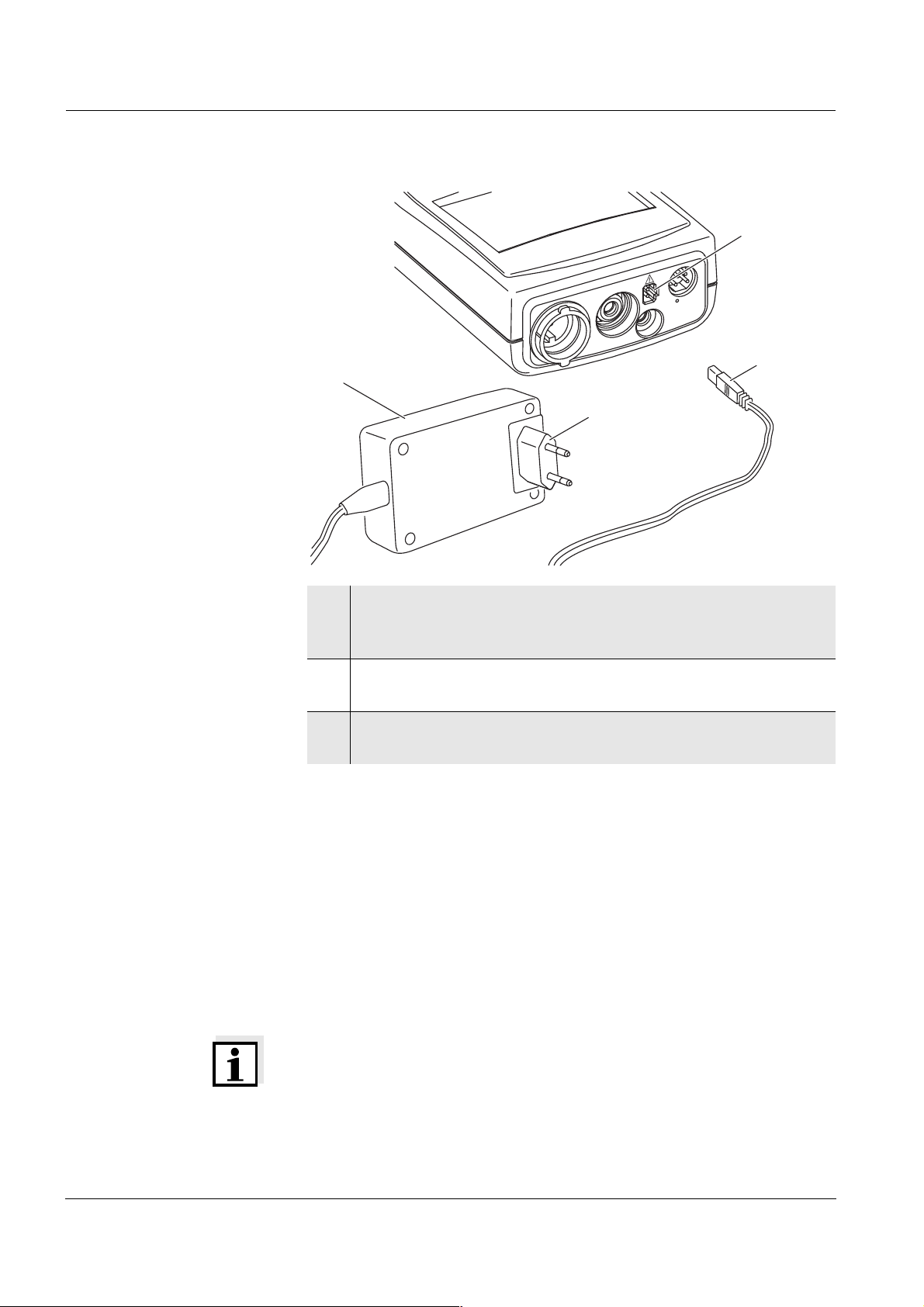
Commissioning Multi 3500i
4
3
2
1
1 If necessary, replace the Euro plug (1) on the plug-in power
supply unit (2) by the country-specific plug suitable for your
country.
2 Connect the plug (3) to the socket (4) of the measuring instru-
ment.
3 Connect the plug-in power supply unit to an easily accessible
mains socket.
3.3 Initial commissioning
Perform the following activities:
z For mains operation and charging the batteries: Connect the plug-in
power supply unit (see section 3.2 P
z Switch on the measuring instrument (see section 4.1)
z Set the language (see section 4.2.3)
z Set the date and time (see section 4.2.4)
Note
When you set the language, date and time according to the mentioned
sections of this operating manual you will quickly be familiar with the
simple operation of the Multi 3500i.
OWER SUPPLY).
12
Page 15

Multi 3500i Operation
4 Operation
4.1 Switching on the measuring instrument
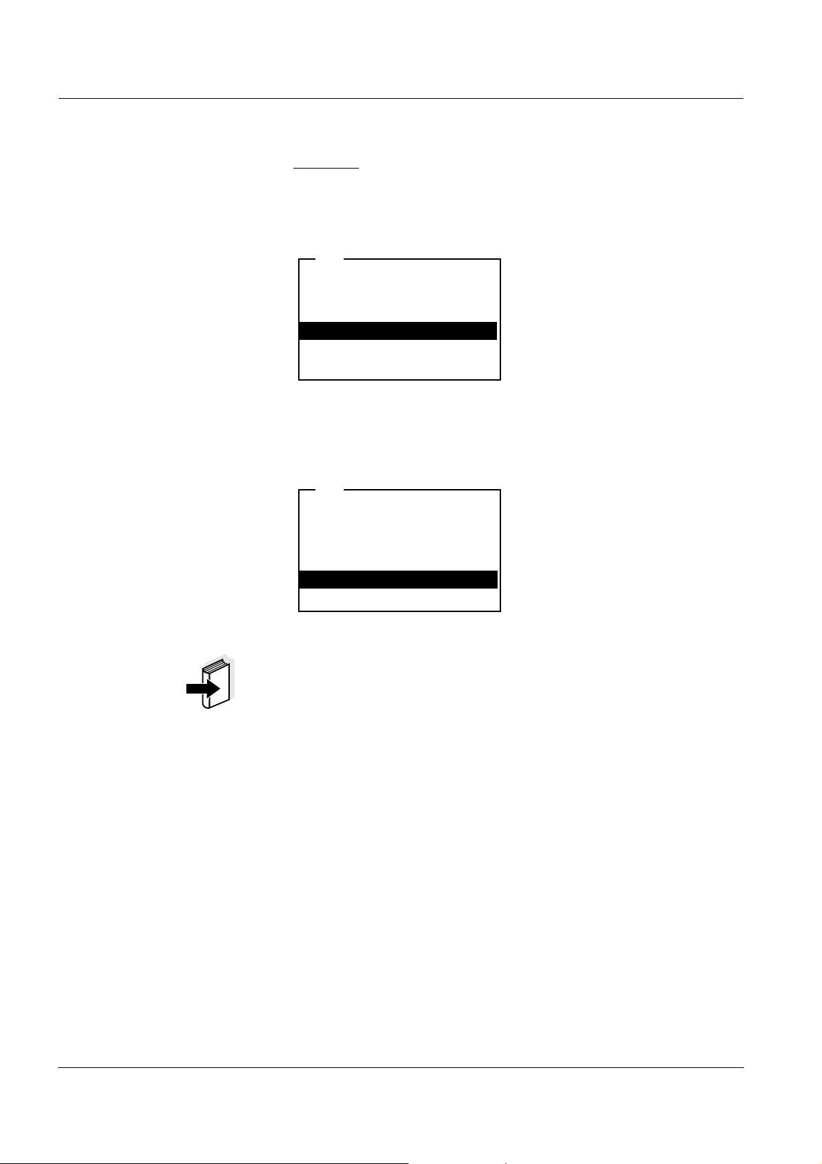
Switching on Press the <ON/OFF> key.
The measured value display appears.
pH
6.949
25.0
Switching off Press the <ON/OFF> key.
Automatic switchoff The instrument has an automatic switchoff function in order to save the
batteries (see section 4.3.3). The automatic switchoff switches off the
measuring instrument if no key is pressed for an adjustable period.
The automatic switchoff is not active
z if the power is supplied by the plug-in power supply unit,
z if the Automatic data storage function is active, or with automatic
data transmission
z if the communication cable and a PC with a running communication
program are connected,
z if the printer cable is connected (for external printers).
Display illumination
with battery operation
During battery operation, the measuring instrument automatically
switches off the display illumination if no key has been pressed for
15 seconds. The illumination is switched on with the next keystroke
again.
°C
13
Page 16

Operation Multi 3500i
4.2 General operating principles
This section contains basic information of the operation of the
Multi 3500i.
Operating elements,
display
Operating modes,
navigation
An overview of the operating elements and the display is given in
section 1.3 and section 1.4.
An overview of the operating modes and navigation of the Multi 3500i
is given in section 4.2.1 and section 4.2.2.
4.2.1 Operating modes
The instrument has the following operating modes:
z Measuring
The measuring data of one to three sensors is displayed in the
measured value display
z Calibration
The course of a calibration with calibration information, functions
and settings is displayed
z Data storage
The measuring instrument stores measuring data automatically or
manually
z Transmitting data
The measuring instrument transmits measuring data and calibration
records to the serial interface automatically or manually.
z Setting
The system menu or a sensor menu with submenus, settings and
functions is displayed
14
Page 17

Multi 3500i Operation
4.2.2 Navigation
Measured value display In the measured value display, you can
z select a measuring window with <▲><▼> and
open the relevant measuring menu by shortly
pressing
<MENU/ENTER>.
z open the system menu with the sensor-independent settings by
pressing <MENU/ENTER> for a long
time (approx. 1 s).
z change the display in the selected measuring window
(e. g. pH < − > mV) by pressing <M>.
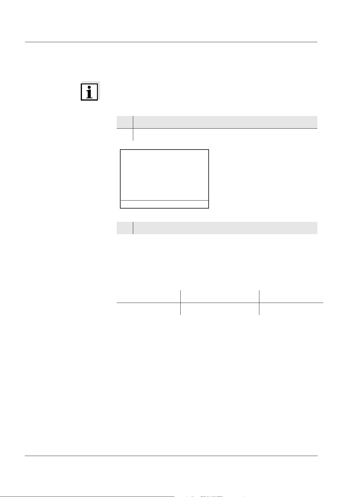
Menus and dialogs The menus for settings and dialogs in courses contain further sub-
menus. The selection is made with the <▲><▼> keys. The current se-
lection is displayed in reverse video.
z Submenus
The name of the submenu is displayed at the upper edge of the
frame. Submenus are opened by confirming with <MENU/ENTER>.
Example:
System
General
Interface
Clock function
Reset
z Settings
Settings are indicated by a colon. The current setting is displayed on
the right-hand side. The setting mode is opened with
<MENU/ENTER>. Subsequently, the setting can be changed with
<▲><▼> and <MENU/ENTER>.
Example:
System
Language: Deutsch
Beep
: Off
Illumination: On
Contrast: 48 %
Temperature unit
Switchoff time: 30 min
: °C
15
Page 18
Operation Multi 3500i
z Functions
Functions are designated by the name of the function. They are immediately carried out by confirming with <MENU/ENTER>.
Example: Display the Calibration record function.
pH
Calibration type: TEC
Calibration interval
Unit for slope: mV/pH
Calibration record
:
i 2.00 4.01 7.00 10.01
: 7 d
Messages Information or operating instructions are designated by the i symbol.
They cannot be selected.
Example:
pH
i Buffer recognition TEC
i Immerse sensor in buffer 1
Set temperature: 25 °C
Continue
Note
The principles of navigation are explained in the two following sections
by reference of examples:
z Set the language (see section 4.2.3)
z Set the date and time (see section 4.2.4).
16
Page 19
Multi 3500i Operation
4.2.3 Example 1 on navigation: Setting the language
1 Press the <ON/OFF> key.
The measured value display appears.
The instrument is in the measuring ode.
pH
7.00
25.0
°C
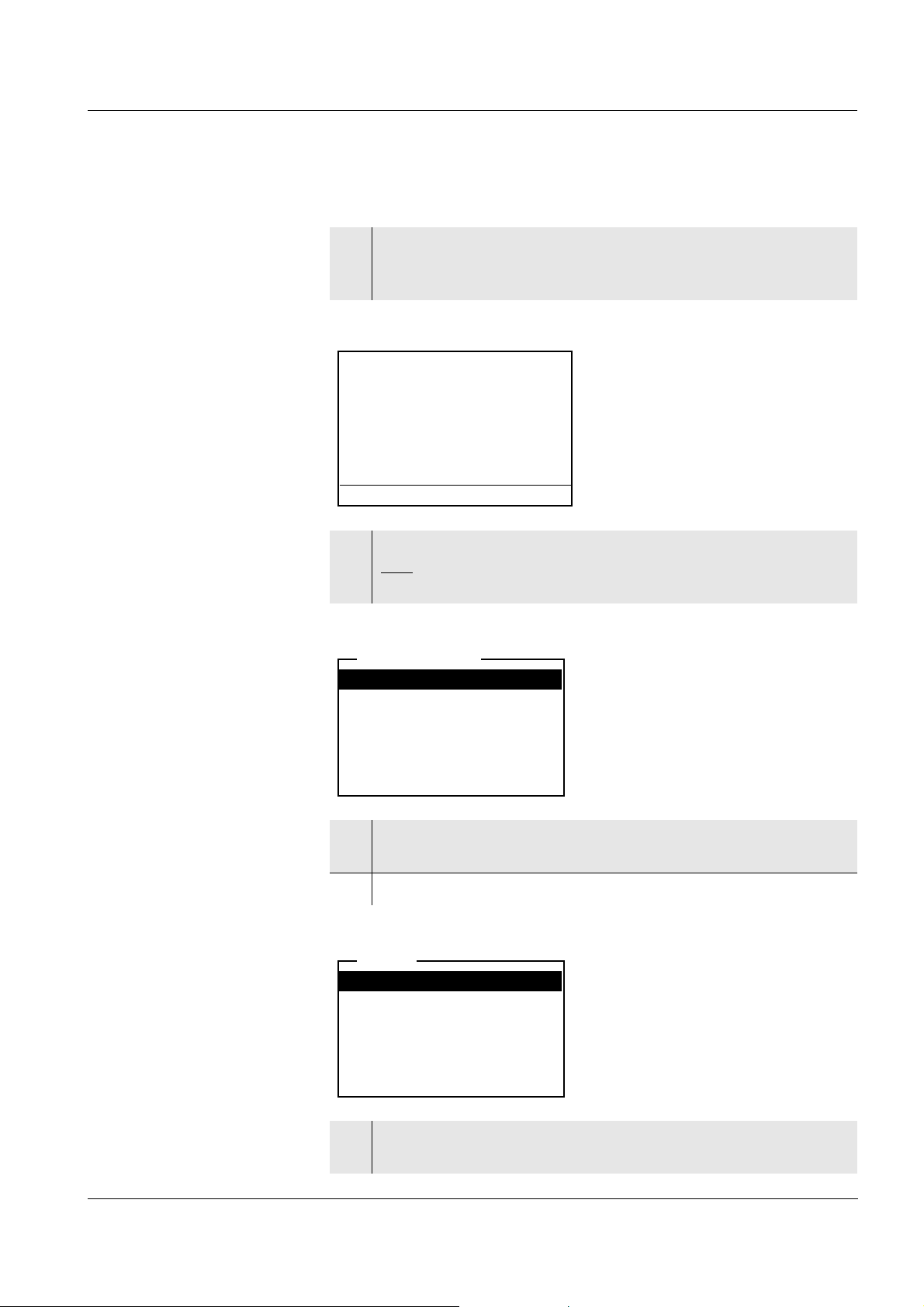
2 Open the system menu by pressing <MENU/ENTER> for a
long
time (approx. 1 s).
The instrument is in the setting mode.
Storage & config
Data storage
Display
System
3 Select the System submenu with <▲><▼>.
The current selection is displayed in reverse video.
4 Open the System
submenu with <MENU/ENTER>.
System
General
Interface
Clock function
Reset
5 Select the General submenu with <▲><▼>.
The current selection is displayed in reverse video.
17
Page 20
Operation Multi 3500i
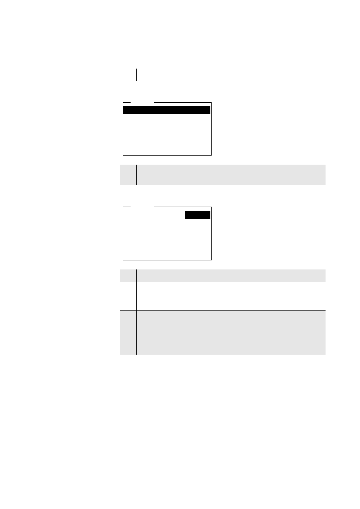
6 Open the General submenu with <MENU/ENTER>.
System
Language: Deutsch
Beep
: Off
Illumination: On
Contrast: 48 %
Temperature unit
Switchoff time: 30 min
: °C
7 Open the setting mode for the Language with
<MENU/ENTER>.
System
Language: Deutsch
Beep: Off
Illumination: On
Contrast
Temperature unit: °C
Switchoff time: 30 min
: 48 %
8 Select the required language with <▲><▼>.
9 Confirm the setting with <MENU/ENTER>.
The setting becomes active the next time the system menu is
called up.
10 To make further settings, switch to the next higher menu level
with <ESC>.
or
Switch to the measured value display with <M>.
The instrument is in the measuring ode.
18
Page 21
Multi 3500i Operation
4.2.4 Example 2 on navigation: Setting the date and time
The measuring instrument has a clock with a date function. The date
and time are indicated in the status line of the measured value display.
The indication can be switched off. When storing measured values and
calibrating, the current date and time are automatically stored as well.
The correct setting of the date and time and date format is important for
the following functions and displays:
z Current date and time
z Calibration date
z Identification of stored measured values.
Therefore, check the time at regular intervals.
Note
After a fall of the supply voltage (empty batteries), the date and time are
reset to 01.01.2003, 00:00 hours.
Setting the date, time
and date format
The data format can be switched from the display of day, month, year
(dd.mm.yy) to the display of month, day, year (mm/dd/yy or mm.dd.yy).
1 In the measured value display:
Open the system menu by pressing <MENU/ENTER> for a
long
time (approx. 1 s).
The instrument is in the setting operating mode.
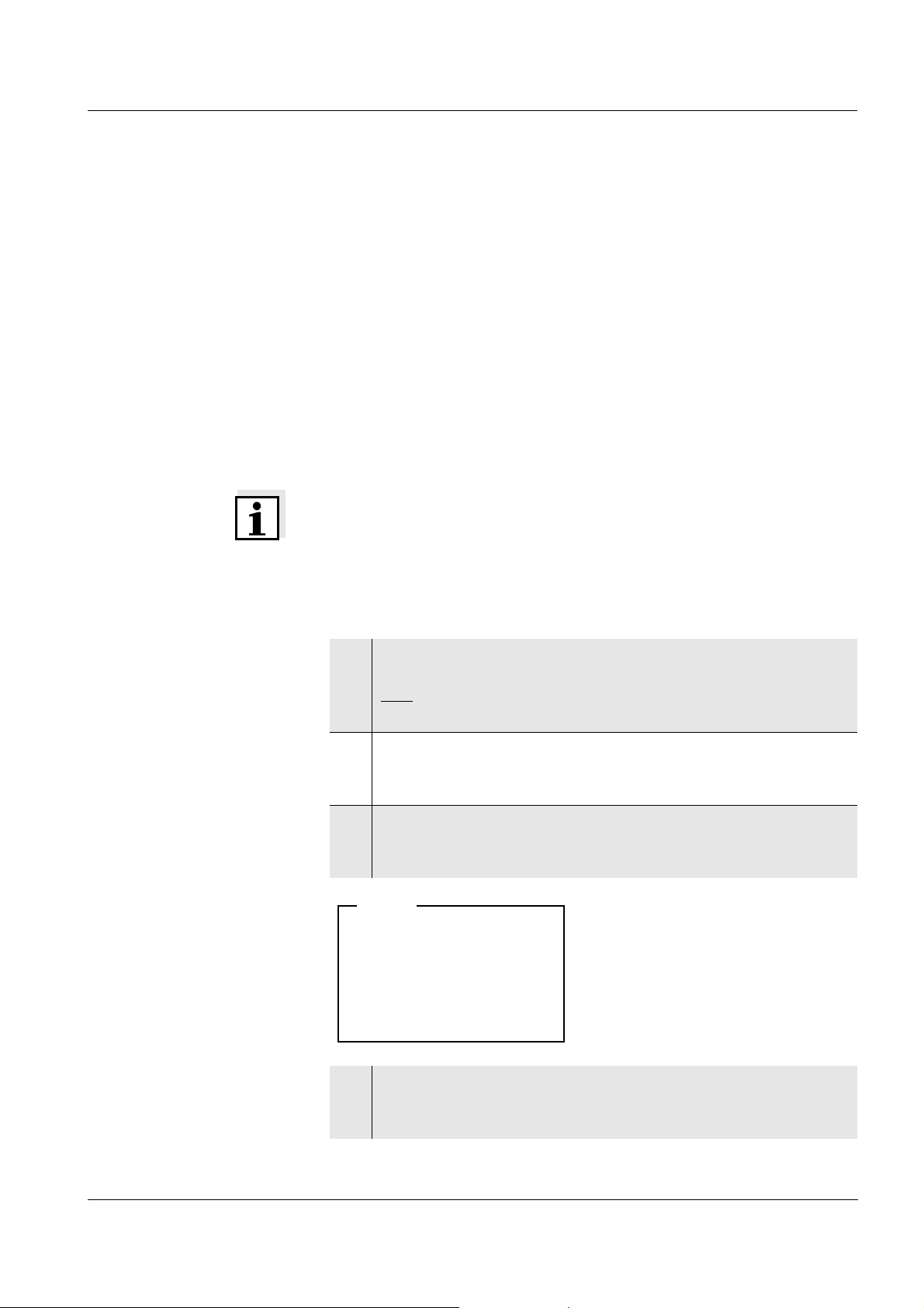
2 Select and confirm the System / Clock function menu with
<▲><▼> and <MENU/ENTER>.
The setting menu for the date and time opens up.
3 Select and confirm the Time menu with <▲><▼> and
<MENU/ENTER>.
The seconds are highlighted.
System
Time: 14:53:40
Date
: 30.10.03
Date format: dd.mm.yy
4 Change and confirm the setting with <▲><▼> and <MENU/
ENTER>.
The minutes are highlighted.
19
Page 22

Operation Multi 3500i
5 Change and confirm the setting with <▲><▼> and <MENU/
ENTER>.
The hours are highlighted.
6 Change and confirm the setting with <▲><▼> and <MENU/
ENTER>.
The time is set.
7 If necessary, set the Date and Date format. The setting is made
similarly to that of the time.
8 If necessary, select and set the Date with <▲><▼> and
<MENU/ENTER>.
9 To make further settings, switch to the next higher menu level
with <ESC>.
or
Switch to the measured value display with <M>.
The instrument is in the measuring operating mode.
20
Page 23
Multi 3500i Operation
4.3 System settings (system menu)
The system menu comprises the following settings:
z Data storage (see section 4.3.1)
z Display (see section 4.3.2)
z System (see section 4.3.3).
4.3.1 Data storage
This menu contains all functions to display, edit and erase stored measured values and calibration records.
Note
Detailed information on the data storage functions of the Multi 3500i is
given in section 4.8.
4.3.2 Display
With the aid of Display submenu, you can modify the measured value
display to meet your requirements. When doing so, you can display or
hide the following elements:
z pH/ISE measuring window
z DO measuring window
z Conductivity measuring window
z Date indication in the status line
z Time indication in the status line
Note
When several sensors or multiple sensors (e.g. ConOx) are connected,
all available measured variables are automatically displayed. If you do
not wish to have all measured values displayed, you can hide measured values of individual sensors.
21
Page 24

Operation Multi 3500i
Settings To open the system menu in the measured value display, press the
<MENU/ENTER> key for approx. 1 s
. After completing the settings,
switch to the measured value display with <M>.
Menu item Setting Description
Display / Time On
Off
Display / Date On
Off
Display / pH On
Off
Display / O2 On
Off
Display / Cond On
Off
Display of the time in the system
status line
Display of the date in the system
status line
Display of the pH/ISE measuring
window.
This menu item is only visible if the
electrode and an additional sensor
are connected.
Display of the DO measuring window.
This menu item is only visible if a
DO sensor is connected.
Display of the conductivity measuring window.
This menu item is only visible if a
conductivity measuring cell is connected.
22
Page 25

Multi 3500i Operation
4.3.3 System
Overview The following sensor-independent instrument features can be adjusted
in the system menu/System and its submenus:
z Menu language
z Beep on keystroke
z Display illumination
z Display contrast
z Unit of the temperature display
z Interval of the automatic switchoff
z Data interface
z Clock and date function
z Function to reset all sensor-independent system settings to the de-
fault condition
Settings To open the system menu in the measured value display, press the
<MENU/ENTER> key for approx. 1 s
. After completing the settings,
switch to the measured value display with <M>.
Menu item Setting Description
System / General /
Language
Deutsch
English
Select the menu language
(further)
System / General /
Beep
System / General /
Illumination
System / General /
Contrast
System / General /
Temperature unit
On
Off
On
Off
Switch on/off the beep on
keystroke
Switching the display illumination on/off
0 ... 100 % Changing the display con-
trast
°C
°F
Temperature unit,
degrees Celsius or degrees
Fahrenheit.
All temperatures are displayed with the selected unit.
System / General /
Switchoff time
10, 20, 30, 40,
50 min,
1 2 3 4 5 10 15
20 24 h
The automatic switchoff automatically switches the measuring instrument off if no
entry is made for a specified
period of time (switchoff interval). This saves the batteries.
23
Page 26

Operation Multi 3500i
Menu item Setting Description
System / Interface /
Baud rate
1200, 2400,
4800, 9600,
Baud rate of the data interface
19200
System / Interface /
Output format
ASCII
CSV
Output format for data transmission
For details, see section 4.9
System / Interface /
Header
Yes
No
Option for output in csv format. "Yes" creates a header
in the table.
System / Clock function
Time
Date
Settings of time and date.
For details, see section 4.2.4
Date format
System / Reset - Resets the system settings to
the default values.
For details, see
section 4.10.2
24
Page 27

Multi 3500i Operation
4.4 pH value / ORP voltage
4.4.1 General information
You can measure the following variables:
z pH value [ ]
z ORP [mV]
Caution
When connecting an earthed PC/printer, measurements cannot be
performed in earthed media as incorrect values would result. The
RS232 interface is not galvanically isolated.
Temperature
measurement
For reproducible pH measurements, it is essential to measure the temperature of the test sample.
You have the following possibilities of measuring the temperature:
z Automatic measurement of the temperature by the temperature sen-
sor (NTC30 or Pt 1000) integrated in electrode.
z Measurement of the temperature by the integrated temperature sen-
sor of a simultaneously connected DO sensor or conductivity measuring cell in the test sample.
z Manual determination and input of the temperature.
The measuring instrument recognizes whether a suitable sensor is
connected and automatically switches on the temperature measurement.
25
Page 28
Operation Multi 3500i
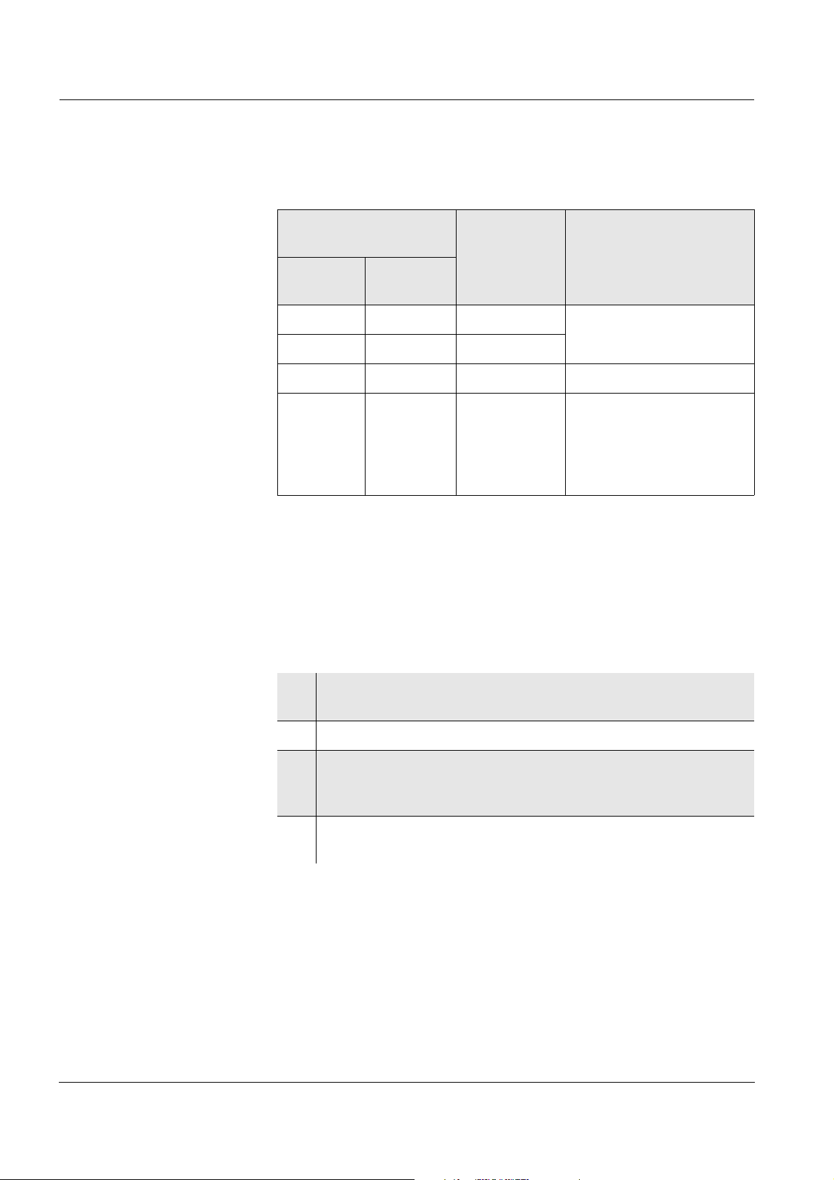
The display of the temperature indicates the active temperature measuring mode:
Temperature
sensor
Resolution
of the temp.
Mode
display
pH Cond or
Oxi
yes - 0.1 °C Automatic with pH tem-
yes yes 0.1 °C
perature sensor
-- 1°C Manual
-yes0.1 °C,
measured
temperature
value flashes
The temperature value of
the second sensor (Cond
or Oxi) in the same test
sample is taken over for
pH measurement*
* If you do not wish that, you can:
– either disconnect the 2nd sensor and use the manual temperature
input or
– use an electrode with a temperature sensor.
Preparatory activities Perform the following preparatory activities when you want to measure:
1 Connect a pH or ORP electrode to the measuring instrument.
The pH/ISE measuring window is displayed.
2 If necessary, select the pH or mV display with <M>.
3 Adjust the temperature of the solutions and measure the cur-
rent temperature if the measurement is made without a temperature sensor.
4 Calibrate or check the measuring instrument with the elec-
trode.
26
Page 29

Multi 3500i Operation
4.4.2 Measuring the pH value
1 Perform the preparatory activities according to section 4.6.1.
2 Immerse the pH electrode in the test sample.
pH
6.949
AutoRead
(Drift control)
Criteria With identical measurement conditions, the following applies:
24.8
3 Select the pH or mV display with <M>.
The AutoRead function (drift control) continually checks the stability of
the measurement signal. The stability has a considerable impact on the
reproducibility of measured values. The display of the measured variable flashes until a stable measured value is available.
Measured
variable
pH value Better than 0.01 > 30 seconds
°C
Reproducibility Response time
27
Page 30
Operation Multi 3500i
4.4.3 Measuring the ORP voltage
Note
ORP electrodes are not calibrated. However, you can check ORP electrodes using a test solution.
1 Perform the preparatory activities according to section 4.6.1.
2 Submerse the ORP electrode in the sample.
U
AutoRead
(drift control)
Criteria With identical measurement conditions, the following applies:
157.0
24.8
3 Select the mV display with <M>.
The AutoRead function (drift control) continually checks the stability of
the measurement signal. The stability has a considerable impact on the
reproducibility of measured values. The display of the measured variable flashes until a stable measured value is available.
Measured variable Reproducibility Response time
ORP voltage better than 0.6 mV > 30 seconds
mV
°C
28
Page 31

Multi 3500i Operation
4.4.4 Settings for pH and ORP measurements
Overview The following settings are possible for pH and ORP measurements:
z Resolution
z Calibration interval
z Buffers for calibration
z Unit for slope
z Calibration record (display)
Settings The settings are made in the measuring menu of the pH/ORP measure-
ment. To open the settings, activate the relevant measuring window in
the measured value display and press the <MENU/ENTER> key shortly. After completing the settings, switch to the measured value display
with <M>.
Menu item Possible
setting
Calibration /
1 ... 999 d Calibration interval for the pH elec-
Calibration interval
Calibration /
Calibration type
TEC
NIST/DIN
ConCal
Calibration / Unit
for slope
Calibration /
mV/pH
%
- Displays the calibration record of
Calibration
record
Man. temperature
-20 ...
+130 °C
Description
trode (in days).
The measuring instrument reminds
you to calibrate regularly by the
flashing sensor symbol in the measuring window.
Buffer sets to be used for pH calibration.
For details, see section 4.4.5.
Unit of the slope.
The % display refers to the Nernst
slope of
-59.16 mV/pH (100 x determined
slope/Nernst slope).
the last calibration.
Entry of the manually determined
temperature. For measurements
without temperature sensor only.
Reset - Resets all sensor settings to the
delivery condition (see
section 4.10.1).
High resolution On
Off
Resolution of the pH display:
On = 0.001
Off = 0.01
29
Page 32

Operation Multi 3500i
4.4.5 pH calibration
Why calibrate? pH electrodes age. This changes the asymmetry (zero point) and slope
of the pH electrode. As a result, an inexact measured value is displayed. Calibration determines the current values of the asymmetry
and slope of the electrode and stores them in the measuring instrument. Thus, you should calibrate at regular intervals.
When to calibrate? z After connecting another electrode
z When the sensor symbol flashes:
– after the calibration interval has expired
– after a voltage interruption (empty batteries)
Buffer sets for
calibration
You can use the buffer sets quoted in the table for an automatic calibration. The pH values are valid for the specified temperature values. The
temperature dependence of the pH values is taken into account during
calibration.
Buffer set Name on the
display
pH values at
25 °C
Technical buffer solutions TEC 2.00
4.01
7.00
10.01
NIST/DIN buffer solutions NIST/DIN 1.679
4.006
6.865
9.180
12.454
(user-defined single-point or twopoint calibration)
ConCal pH 7.0 ± 0.5
and any other
buffer solution
Note
The buffers are selected in the sensor menu (setting, Calibration type,
see section 4.4.4).
30
Page 33

Multi 3500i Operation
Calibration points Calibration can be performed using one, two or three buffer solutions in
any order (single-point, two-point or three-point calibration). The measuring instrument determines the following values and calculates the
calibration line as follows:
Determined
Displayed calibration data
values
1-point ASY z Asymmetry = ASY
z Slope = Nernst slope
(-59.16 mV/pH at 25 °C)
2-point ASY
SLO
3-point ASY
SLO
z Asymmetry = ASY
z Slope = SLO
z Asymmetry = ASY
z Slope = SLO
The calibration line is calculated
by linear regression.
Note
You can display the slope in the units, mV/pH or % (see section 4.3.3).
AutoRead In calibration, the AutoRead function is automatically activated.
The current AutoRead measurement can be terminated at any time
(accepting the current value).
Calibration record When finishing a calibration, the new calibration values are displayed
as an informative message (
i symbol) first. Then you can decide
whether you want to take over these values of the new calibration or
whether you want to continue measuring with the old calibration data.
After accepting the new calibration values the calibration record is displayed.
31
Page 34

Operation Multi 3500i
Display calibration data
and output to interface
You can have the data of the last calibration displayed (see
section 4.8.5). Subsequently, you can transmit the displayed calibration data to the interface, e. g. to a printer or PC, with the <PRT> key.
Note
The calibration record is automatically transmitted to the interface after
calibrating.
Sample record:
03.11.03 07:14
CALIBRATION pH
03.11.03 07:10:45
Multi 3500i ser. no. 12345678
Cal. interval 7 d
AutoCal TEC
Buffer 1 4.01
Buffer 2 7.00
Buffer 3 10.01
Voltage 1 184.0 mV 24.0 °C
Voltage 2 0.0 mV 24.0 °C
Voltage 3 -177.0 mV 24.0 °C
Slope -60.2 mV/pH
Asymmetry 3.0 mV
Sensor +++
32
Page 35

Multi 3500i Operation
Calibration evaluation After calibrating, the measuring instrument automatically evaluates the
calibration. The asymmetry and slope are evaluated separately. The
worse evaluation of both is taken into account. The evaluation appears
on the display and in the calibration record.
Display Calibration
record
+++ -15 ... +15 -60.5 ... -58
++ -20 ... +20 -58 ... -57
+ -25 ... +25 -61 ... -60.5
- -30 ... + 30 -62 ... -61
Clean the electrode according
to the electrode operating
manual
Error Error
Perform error elimination according to chapter 6 W
DO IF...
HAT TO
Asymmetry
[mV]
< -30 or
> 30
Slope
[mV/pH]
or
-57 ... -56
or
-56 ... -50
< -62 or
> -50
Preparatory activities Perform the following preparatory activities when you want to calibrate:
1 Connect the pH electrode to the measuring instrument.
The pH/ISE measuring window is displayed.
2 Keep the buffer solutions ready. Adjust the temperature of the
buffer solutions, or measure the current temperature, if you
measure without a temperature sensor.
33
Page 36

Operation Multi 3500i
4.4.6 Carrying out the TEC and NIST/DIN calibration
The two calibration procedures only differ in the usage of different buffer sets (see section 4.4.5). Make sure that the Calibration type is correctly set in the sensor menu (see section 4.4.4).
For this procedure, use any one, two or three WTW technical buffer solutions in ascending or descending order.
The TEC calibration is described below. With the NIST/DIN calibration,
the NIST/DIN buffer recognition and different nominal buffer values are
displayed. Apart from that, the procedure is identical.
Note
The TEC calibration for pH 10.01 is optimized for the WTW technical
buffer solution TEP 10 Trace or TPL 10 Trace. Other buffer solutions
can lead to an erroneous calibration. The correct buffer solutions are
given in the WTW catalog or in the Internet.
1 In the measured value display, select the pH or mV measuring
window with <▲><▼> and <M>.
2 Start the calibration with <CAL>.
The calibration display appears.
pH <CAL>
i Buffer recognition TEC
i Immerse sensor in buffer 1
Continue
3 Immerse the electrode in buffer solution 1.
4 If the Set temperature menu item appears, measure and enter
the temperature of the buffer manually (measurement without
temperature sensor).
5 Select Continue with <▲><▼> and press <MENU/ENTER>.
The buffer is measured.
The measured value is checked for stability (AutoRead).
34
Page 37

Multi 3500i Operation
pH <CAL>
i Buffer value = 7.000
i U = 3.0 mV
i Temperature =
24.8 °C
Displayed:
– Recognized nominal buffer
value (referring to 25 °C)
– current electrode voltage
– current temperature value
Terminate AutoRead
6 Wait for the end of the AutoRead measurement or accept the
calibration value with <MENU/ENTER>.
The calibration display for the next buffer appears.
pH <CAL>
i Buffer recognition TEC
i Immerse sensor in buffer 2
Exit with one point calibration
Continue
7 For single-point calibration, select Exit with one point calibra-
tion with <▲><▼> and confirm with <MENU/ENTER> .
The calibration is completed as a single-point calibration.
The new calibration values are displayed as a message (
i).
You have the following options:
z Accept the new calibration values with <MENU/ENTER>.
Subsequently, the calibration record is displayed and output
to the interface at the same time.
z To switch to the measured value display without
accepting
the new calibration values, press <M> or <ESC>.
Note
For single-point calibration, the instrument uses the Nernst slope
(-59.16 mV/pH at 25 °C) and determines the asymmetry of the electrode.
35
Page 38

Operation Multi 3500i
Continuing for two-point
calibration
(Calibration type TEC)
8 Thoroughly rinse the electrode with distilled water.
9 Immerse the electrode in buffer solution 2.
10 If the Set temperature menu item appears, measure and enter
the temperature of the buffer manually (measurement without
temperature sensor).
11 Select Continue with <▲><▼> and press <MENU/ENTER>.
The buffer is measured.
The measured value is checked for stability (AutoRead).
pH <CAL>
i Buffer value = 10.011
i U = -177.0 mV
i Temperature = 24.8 °C
Terminate AutoRead
12 Wait for the end of the AutoRead measurement or Terminate
AutoRead and accept the calibration value with
<MENU/ENTER>.
The calibration display for the next buffer appears.
pH <CAL>
i Buffer recognition TEC
i Immerse sensor in buffer 3
Exit with 2 point calibration
Continue
13 For two-point calibration, select Exit with 2 point calibration with
<▲><▼> and confirm with <MENU/ENTER>.
The calibration is completed as a two-point calibration.
The new calibration values are displayed as a message (
i).
You have the following options:
z Accept the new calibration values with <MENU/ENTER>.
Subsequently, the calibration record is displayed and output
to the interface at the same time.
z To switch to the measured value display without
accepting
the new calibration values, press <M> or <ESC>.
36
Page 39

Multi 3500i Operation
Continuing for three-
point calibration
(Calibration type TEC)
14 Thoroughly rinse the electrode with distilled water.
15 Immerse the electrode in buffer solution 3.
16 If necessary, measure the temperature of buffer 3 manually,
then enter and confirm it with <▲><▼> and <MENU/ENTER>
in the Set temperature setting.
17 Select Continue with <▲><▼> and press <MENU/ENTER>.
The buffer is measured.
The measured value is checked for stability (AutoRead).
pH <CAL>
i Buffer value = 4.010
i U = 184.0 mV
i Temperature = 24.8 °C
Terminate AutoRead
18 Wait for the end of the AutoRead measurement or Terminate
AutoRead and accept the calibration value with
<MENU/ENTER>.
The new calibration values are displayed as a message (
i).
You have the following options:
z Accept the new calibration values with <MENU/ENTER>.
Subsequently, the calibration record is displayed and output
to the interface at the same time.
z To switch to the measured value display without
the new calibration values, press <M> or <ESC>.
accepting
37
Page 40

Operation Multi 3500i
4.4.7 Carrying out a ConCal calibration
Single-point calibration Use any buffer solution for this rapid method.
The calibration will be the more exact the nearer the pH value of the
buffer solution is to that of the test sample.
Two-point calibration Use two buffer solutions for this procedure:
z first buffer solution: pH 7.0 ± 0.5
z any other buffer solution
For this calibration, Calibration type ConCal must be set in the sensor
menu (see section 4.4.4).
1 In the measured value display, select the pH or mV measuring
window with <▲><▼> and <M>.
2 Start the calibration with <CAL>.
The calibration display appears.
pH <CAL>
i Immerse sensor in buffer 1
i Temperature = 24.8 °C
Set buffer: 7.00
Continue
3 Thoroughly rinse the electrode with distilled water.
4 Immerse the electrode in buffer solution 1.
5 Set the nominal buffer value for the measured temperature with
<MENU/ENTER> and <▲><▼>. Then confirm the value with
<MENU/ENTER>.
6 If the Set temperature menu item appears, measure and enter
the temperature of the buffer manually (measurement without
temperature sensor).
7 Select Continue with <▲><▼> and press <MENU/ENTER>.
The buffer is measured.
The measured value is checked for stability (AutoRead).
38
Page 41

Multi 3500i Operation
pH <CAL>
i Buffer value = 6.80
i U = 12.0 mV
i Temperature =
Terminate AutoRead
24.8 °C
8 Wait for the end of the AutoRead measurement or Terminate
AutoRead and accept the calibration value with
<MENU/ENTER>.
The calibration display for the next buffer appears.
pH <CAL>
i Immerse sensor in buffer 2
i Temperature = 24.8 °C
Exit with one point calibration
Set buffer: 8.27
Continue
9 For single-point calibration, select Exit with one point calibra-
tion with <▲><▼> and confirm with <MENU/ENTER>.
The calibration is completed as a single-point calibration.
The new calibration values are displayed as a message (
i).
You have the following options:
z Accept the new calibration values with <MENU/ENTER>.
Subsequently, the calibration record is displayed and output
to the interface at the same time.
z To switch to the measured value display without
accepting
the new calibration values, press <M> or <ESC>.
Note
For single-point calibration, the instrument uses the Nernst slope
(-59.16 mV/pH at 25 °C) and determines the asymmetry of the electrode.
39
Page 42

Operation Multi 3500i
Continuing for two-point
calibration
(Calibration type
ConCal)
10 Thoroughly rinse the electrode with distilled water.
11 Immerse the electrode in buffer solution 2.
12 Set the nominal buffer value with <MENU/ENTER> and
<▲><▼>. Then confirm the value with <MENU/ENTER>.
13 If the Set temperature menu item appears, measure and enter
the temperature of the buffer manually (measurement without
temperature sensor).
14 Select Continue with <▲><▼> and press <MENU/ENTER>.
The buffer is measured.
The measured value is checked for stability (AutoRead).
pH <CAL>
i Buffer value = 8.85
i U = -102.0 mV
i Temperature =
Terminate AutoRead
24 °C
15 Wait for the end of the AutoRead measurement or Terminate
AutoRead and accept the calibration value with
<MENU/ENTER>.
The new calibration values are displayed as a message (
i).
You have the following options:
z Accept the new calibration values with <MENU/ENTER>.
Subsequently, the calibration record is displayed and output
to the interface at the same time.
z To switch to the measured value display without
accepting
the new calibration values, press <M> or <ESC>.
40
Page 43

Multi 3500i Operation
4.5 Ion concentration
4.5.1 General information
Note
Incorrect calibration of ion sensitive electrodes will result in incorrect
measured values. Calibrate regularly before measuring.
Caution
When connecting an earthed PC/printer, measurements cannot be
performed in earthed media as incorrect values would result. The
RS232 interface is not galvanically isolated.
Temperature
measurement in ISE
measurements
For reproducible measurements of the ion concentration, it is essential
to measure the temperature of the test sample.
You have the following possibilities of measuring the temperature:
z Measurement of the temperature by the integrated temperature sen-
sor of a simultaneously connected DO sensor or conductivity measuring cell in the test sample.
z Manual determination and input of the temperature.
The measuring instrument recognizes whether a suitable sensor is
connected and automatically switches on the temperature measurement.
The display of the temperature indicates the active temperature measuring mode:
Temperature
sensor,
Cond or Oxi
- 1°C Manual
yes 0.1 °C,
Resolution
of the temp.
display
measured temperature value
flashes
Mode
The temperature value of
the second sensor (Cond
or Oxi) in the same test
sample is taken over for
measurement*
* If this is not required you can unplug the second sensor and enter the
temperature manually.
41
Page 44

Operation Multi 3500i
Preparatory activities Perform the following preparatory activities when you want to measure:
1 Connect the ISE combination electrode to the measuring in-
strument. The pH/ISE measuring window is displayed.
2 If necessary, select the ISE display (unit, mg/l) with <M>.
3 Measure the temperature of the test sample using a thermom-
eter.
4 Calibrate or check the measuring instrument with the elec-
trode.
Note
While no valid calibration is available, e.g. in the delivery condition, "Error" appears in the measured value display.
AutoRead
(drift control)
Criteria With identical measurement conditions, the following applies:
4.5.2 Measuring the ion concentration
1 Perform the preparatory activities according to section 4.5.1.
2 Immerse the electrode in the test sample.
ISE
0.157
The AutoRead function (drift control) continually checks the stability of
the measurement signal. The stability has a considerable impact on the
reproducibility of measured values. The display of the measured variable flashes until a stable measured value is available.
25
mg/l
°C
Temperature while cali-
brating and measuring
42
Measuring signal Reproducibility Response time
Electrode
voltage
For precise ISE measurements the temperature difference between
measurement and calibration should not be greater that 2 K. Therefore,
better than 0.1 mV > 30 seconds
Page 45

Multi 3500i Operation
adjust the temperature of the standard and measuring solutions accordingly. If the temperature difference is greater the [TempErr] warning appears in the measured value display.
4.5.3 Settings for ISE measurements
Overview The following settings are possible for ISE measurements:
z Calibration record (display)
Settings The settings are made in the measuring menu of the ISE measure-
ment. To open the settings, activate the relevant measuring window in
the measured value display and press the <MENU/ENTER> key shortly. After completing the settings, switch to the measured value display
with <M>.
Menu item Possible
Description
setting
Calibration / Calibra-
tion record
- Displays the calibration
record of the last calibration.
Man. temperature -20 ... +130 °C Entry of the manually de-
termined temperature. For
measurements without
temperature sensor only.
4.5.4 Calibrating for ISE measurements
Why calibrate? Ion-selective electrodes age and are temperature-dependent. This
changes the slope. As a result, an inexact measured value is displayed.
Calibration determines the current value of the slope of the electrode
and stores it in the instrument.
Thus, you should calibrate before each measurement and at regular intervals.
When to calibrate? z Before any measurement if possible
z After connecting another ISE electrode
z When the sensor symbol flashes, e.g. after a voltage interruption
(empty batteries)
43
Page 46

Operation Multi 3500i
Standard solutions Use two or three different standard solutions. For three-point calibra-
tion, the standard solutions have to be selected in either increasing or
decreasing order.
Temperature while cali-
brating and measuring
ISE Cal This is the conventional two-point or three-point calibration proce-
Standard
Values [mg/l]
solution
Std 1 0.01; 0.02; 0.05; 0.1; 0.2; 0.5; 1; 2; 5; 10; 20; 50; 100;
Std 2
Std 3
200; 500; 1000
If Std 2
If Std 2
> Std 1, Std 3 must be > Std 2
< Std 1, Std 3 must be < Std 2
The calibration line is calculated by linear regression.
Note
The measurement precision is also dependent on the selected standard solutions. Therefore, the selected standard solutions should cover
the expected value range of the subsequent concentration measurement.
For precise ISE measurements the temperature difference between
measurement and calibration should not be greater that 2 K. Therefore,
adjust the temperature of the standard and measuring solutions accordingly. If the temperature difference is greater the [TempErr] warning appears in the measured value display.
dure that uses 2 or 3 freely selectable standard solutions. The concentration expected in the measurement determines the concentration of
the calibration standards.
AutoRead In calibration, the AutoRead function is automatically activated.
Calibration record When finishing a calibration, the new calibration values are displayed
Display calibration data
and output to interface
44
The current AutoRead measurement can be terminated at any time
(accepting the current value).
as an informative message (
i symbol) first. Then you can decide
whether you want to take over these values of the new calibration or
whether you want to continue measuring with the old calibration data.
After accepting the new calibration values the calibration record is displayed.
You can have the data of the last calibration displayed (see
section 4.8.5). Subsequently, you can transmit the displayed calibration data to the interface, e. g. to a printer or PC, with the <PRT> key.
Page 47

Multi 3500i Operation
Note
The calibration record is automatically transmitted to the interface after
calibrating.
Sample record:
03.11.03 07:14
CALIBRATION ISE
03.11.03 07:12:01
Multi 3500i ser. no. 12345678
Standard 1 0.010 mg/l
Standard 2 0.020 mg/l
Voltage 1 0.0 mV 24.0 °C
Voltage 2 9.0 mV 24.0 °C
Slope 29.9 mV
Sensor +++
Calibration evaluation After calibrating, the measuring instrument automatically evaluates the
calibration.
Display Calibration
Magnitude of the slope [mV]
record
+++ 50.0 ... 70.0 or 25.0 ... 35.0
Error Error
Perform error elimination according to chapter 6 W
DO IF...
HAT TO
< 50 or > 70
or
< 25 or > 35
45
Page 48

Operation Multi 3500i
Preparatory activities Perform the following preparatory activities when you want to calibrate:
1 Connect the ISE combination electrode to the measuring in-
strument. The pH/mV/ISE measuring window is displayed.
2 Keep the standard solutions ready.
3 Measure the temperature of the standard solutions using a
thermometer.
Carrying out an
ISE calibration
Proceed as follows to calibrate the instrument:
1 In the measured value display, select the ISE measuring win-
dow with <▲><▼> and <M>.
2 Start the calibration with <CAL>.
The calibration display appears.
ISE <CAL>
i Immerse sensor in std. 1
Set temperature:24 °C
Continue
Set standard: 0.010 mg/l
3 Thoroughly rinse the electrode with distilled water.
4 Immerse the electrode in standard solution 1.
5 Select the Set standard setting with <▲><▼> and press
<MENU/ENTER>.
46
6 Set the concentration of the standard solution with <▲><▼>
and press <MENU/ENTER>.
7 Measure the temperature of the standard solution using a ther-
mometer.
8 Select the Set temperature setting with <▲><▼> and press
<MENU/ENTER>.
9 Set the temperature with <▲><▼> and press
<MENU/ENTER>.
10 Select Continue with <▲><▼> and press <MENU/ENTER>.
The standard solution is measured.
The measured value is checked for stability (AutoRead).
Page 49

Multi 3500i Operation
ISE <CAL>
i Standard = 0.010 mg/l
i U = 0.5 mV
Terminate AutoRead
11 Wait for the end of the AutoRead measurement or accept the
calibration value with <MENU/ENTER>.
The calibration display for the next standard solution appears.
ISE <CAL>
i #1 0.010 mg/l 24 °C
i Immerse sensor in std. 2
Set temperature:24 °C
Continue
Set standard: 0.020 mg/l
Continuing for two-point
calibration
12 Thoroughly rinse the electrode with distilled water.
13 Immerse the electrode in standard solution 2.
14 Select the Set standard setting with <▲><▼> and press
<MENU/ENTER>.
15 Set the concentration of the standard solution with <▲><▼>
and press <MENU/ENTER>.
16 Measure the temperature of the standard solution using a ther-
mometer.
17 Select the Set temperature setting with <▲><▼> and press
<MENU/ENTER>.
18 Set the temperature with <▲><▼> and press
<MENU/ENTER>.
19 Select Continue with <▲><▼> and press <MENU/ENTER>.
The standard solution is measured.
The measured value is checked for stability (AutoRead).
47
Page 50

Operation Multi 3500i
ISE <CAL>
i Standard = 0.020 mg/l
i U = 8.4 mV
Terminate AutoRead
20 Wait for the end of the AutoRead measurement or accept the
calibration value with <MENU/ENTER>.
The calibration display for the next standard solution appears.
ISE <CAL>
i #2 0.020 mg/l 24 °C
i Immerse sensor in std. 3
Set temperature:24 °C
Continue
Exit with 2 point calibration
Set standard: 0.050 mg/l
Continuing for three-
point calibration
21 For two-point calibration, select Exit with 2 point calibration with
<▲><▼> and confirm with <MENU/ENTER> .
The calibration is completed as a two-point calibration.
The new calibration values are displayed as a message (
i).
You have the following options:
z Accept the new calibration values with <MENU/ENTER>.
Subsequently, the calibration record is displayed and output
to the interface at the same time.
z To switch to the measured value display without
accepting
the new calibration values, press <M> or <ESC>.
Repeat the steps 12 to 20 in the same way for the third standard solution. After finishing the last calibration step, the new calibration values
are displayed as a message (
i).
You have the following options:
z Accept the new calibration values with <MENU/ENTER>. Subse-
quently, the calibration record is displayed and output to the interface at the same time.
z To switch to the measured value display without
accepting the new
calibration values, press <M> or <ESC>.
48
Page 51

Multi 3500i Operation
4.6 Dissolved oxygen
4.6.1 General information
You can measure the following variables:
z DO concentration
z DO saturation index ("DO saturation")
z DO partial pressure
DO measurements with the Multi 3500i can be carried out using a ConOx, CellOx 325, DurOx 325 or StirrOx G DO sensor. The stirrer of the
StirrOx G DO sensor has to be supplied with voltage separately using
the NT/pH Mix 540 power supply. The measuring instrument automatically recognizes the type of the connected DO sensor.
The measuring instrument is supplied with the following functions:
z AutoRange (automatic switchover of the measurement range), If a
measuring range is exceeded, AutoRange causes the measuring instrument to automatically change to the next higher measuring
range and back again. Therefore, the instrument always measures
in the measuring range with the highest possible resolution.
z The AutoRead function (drift control) for checking the stability of the
measurement signal. This ensures the reproducibility of the measuring signal. The display of the measured variable flashes until a stable measured value is available.
Note
Incorrect calibration of DO sensors will result in incorrect measured
values.
Calibrate at regular intervals.
Caution
When connecting an earthed PC/printer, measurements cannot be
performed in earthed media as incorrect values would result.
The RS232 interface is not galvanically isolated.
Temperature sensor The DO sensor has an integrated temperature sensor that always mea-
sures the current temperature of the test sample.
49
Page 52

Operation Multi 3500i
Preparatory activities Perform the following preparatory activities when you want to measure:
1 Connect the DO sensor to the measuring instrument.
The DO measuring window is displayed.
2 Calibrate or check the measuring instrument with the sensor.
4.6.2 Measuring
1 Perform the preparatory activities according to section 4.6.1.
2 Immerse the DO sensor in the test sample.
O
2
7.29
25.0
Selecting the
displayed
measured variable
Salinity correction When measuring the concentration of solutions with a salt content of
You can switch between the following displays with <M>:
z DO concentration [mg/l]
z DO saturation [%]
z DO partial pressure [mbar].
more than 1 g/l, a salinity correction is required. For this, you have to
measure and input the salinity of the measured medium first. When the
salinity correction is switched on, the [SAL] indicator is displayed in the
measuring window.
Note
The salinity correction is switched on or off and the salinity is entered
in the measuring menu of the DO measurement (see section 4.6.3).
mg/l
°C
50
Page 53

Multi 3500i Operation
Note
The ConOx double sensor can perform the salinity correction automatically. The conductivity module of the sensor measures the salt content
of the test sample simultaneously with the DO. The measuring instrument takes the measured value into account.
AutoRead
(drift control)
The AutoRead function (drift control) continually checks the stability of
the measurement signal. The stability has a considerable impact on the
reproducibility of measured values. The display of the measured variable flashes until a stable measured value is available.
Criteria With identical measurement conditions, the following applies:
Measuring mode Reproducibility Response time
DO concentration better than 0.05 mg/l > 10 seconds
DO saturation in-
better than 0.6 % > 10 seconds
dex
DO partial pres-
Better than 1.2 mbar > 10 seconds
sure
4.6.3 Settings for DO sensors
Overview The following settings are possible for DO sensors:
z Salinity correction
z Salinity (salinity equivalent)
z Calibration interval
z Comparison measurement
51
Page 54

Operation Multi 3500i
Settings The settings are made in the measuring menu of the DO measurement.
To open the settings, activate the relevant measuring window in the
measured value display and press the <MENU/ENTER> key shortly
.
After completing the settings, switch to the measured value display with
<M>.
Menu item Possible
Description
setting
Calibration / Calibration interval
1 ... 999 d Calibration interval for the DO
sensor (in days).
The measuring instrument reminds you to calibrate regularly by the flashing sensor
symbol in the measuring window.
Calibration / Comparison meas.
On
Off
Enables to adjust the measured value with the aid of a
comparison measurement,
e.g. Winkler titration.
For details, see section 4.6.4.
Calibration / Calibration record
- Displays the calibration
record of the last calibration.
Reset - Resets all sensor settings to
the delivery condition (see
section 4.10.1).
Sal automatic On
Off
Automatic salt content correction for concentration
measurements.
52
Note:
This function is available with
the ConOx double sensor
only
.
Sal correction On
Off
Manual salt content correction for concentration measurements.
Salinity 0.0 ... 70.0 Salinity or salinity equivalent
for the salt content correction.
This function is only available
if the manual salt content correction is switched on.
Page 55

Multi 3500i Operation
4.6.4 DO calibration
Why calibrate? DO sensors age. This changes the slope of the DO sensor. Calibration
determines the current slope of the sensor and stores this value in the
instrument.
When to calibrate? z After connecting another DO sensor
z When the sensor symbol flashes (after the calibration interval has
expired).
Calibration datasets The Multi 3500i administrates three sets of calibration data:
z Set 1 for the type, "CellOx": – CellOx 325, or
– StirrOx G
z Set 2 for the type, "DurOx": – DurOx 325
z Set 3 for the type, "ConOx": – ConOx
Sensors of different types can be calibrated separately from each other.
When a sensor of one type is calibrated, the calibration data of the other types remain stored. The Multi 3500i recognizes the type of the connected sensor and automatically uses the correct calibration data.
Calibration procedure The Multi 3500i provides 2 calibration procedures:
z Calibration in water vapor-saturated air.
Use an OxiCal
®
air calibration vessel for the calibration.
z Calibration via a comparison measurement (e.g. Winkler titration ac-
cording to DIN EN 25813 or ISO 5813). At the same time, the relative slope is adapted to the comparison measurement by a
correction factor. When the correction factor is active, the [Factor] in-
dicator appears in the measuring window.
AutoRead The calibration procedure automatically activates the AutoRead func-
tion.
Display calibration data
and output to interface
You can have the data of the last calibration displayed (see
section 4.8.5). Subsequently, you can transmit the displayed calibration data to the interface, e. g. to a printer or PC, with the <PRT> key.
Note
The calibration record is automatically transmitted to the interface after
calibrating.
53
Page 56

Operation Multi 3500i
Sample record:
03.11.03 07:14
CALIBRATION ConOx
03.11.03 07:12:58
Multi 3500i ser. no. 12345678
Cal. interval 14 d
Relative slope 0.97
Sensor +++
Calibration evaluation After the calibration, the measuring instrument evaluates the current
status of the sensor against the relative slope. The evaluation appears
on the display and in the calibration record. The relative slope has no
effect on the measuring accuracy. Low values indicate that the electrolyte will soon be depleted and the sensor will have to be regenerated.
Display Calibration
record
+++ S = 0.8 ... 1.25
++ S = 0.7 ... 0.8
+ S = 0.6 ... 0.7
Error Error
Perform error elimination according to chapter 6 W
DO IF...
HAT TO
Relative slope
S < 0.6 or S > 1.25
54
Page 57

Multi 3500i Operation
Calibration in
water vapor
saturated air
(air calibration vessel)
For this calibration procedure, the Comparison meas. setting must be
set to Off in the measuring menu.
Proceed as follows to calibrate the instrument:
Note
The sponge in the air calibration vessel must be moist (not wet). Leave
the sensor in the air calibration vessel for a time long enough to adjust.
1 Put the DO sensor into the air calibration vessel.
2 Connect the DO sensor to the measuring instrument.
3 In the measured value display, select the DO measuring win-
dow with <▲><▼> and <M>.
4 Start the calibration with <CAL>.
The calibration display for the relevant sensor type appears.
ConOx <CAL>
i Relative slope = 1.00
i Use air calibration vessel
Continue
5 Put the DO sensor into the air calibration vessel.
6 Press <MENU/ENTER>.
The AutoRead measurement to determine the relative slope
starts.
ConOx <CAL>
i Relative slope = 1.00
i Temperature = 24.8 °C
Terminate AutoRead
7 Wait for the end of the AutoRead measurement or accept the
calibration value with <MENU/ENTER>.
The determined relative slope is displayed as a message (
i).
55
Page 58

Operation Multi 3500i
ConOx <CAL>
i Relative slope = 0.98
i Sensor+++
Accept
8 You have the following options:
z Accept the new calibration values with <MENU/ENTER>.
Subsequently, the calibration record is displayed and output
to the interface at the same time.
Calibration via a
Comparison meas.
z To switch to the measured value display without
accepting
the new calibration values, press <M> or <ESC>.
For this calibration procedure, the Comparison meas. setting must be
set to On in the measuring menu.
Note
Before calibrating via a comparison measurement, the sensor should
be calibrated in the air calibration vessel.
Proceed as follows to calibrate the instrument:
1 Connect the DO sensor to the measuring instrument.
2 Immerse the DO sensor in the reference solution.
3 In the measured value display, select the DO measuring win-
dow with <▲><▼> and <M>.
4 Start the calibration with <CAL>.
The calibration display appears.
56
ConOx <CAL>
i Immerse sensor in ref. sol.
Continue
Page 59

Multi 3500i Operation
5 Press <MENU/ENTER>.
The AutoRead measurement to determine the DO concentration starts.
ConOx <CAL>
i Concentration = 8.5 mg/l
i Temperature = 24.8 °C
Terminate AutoRead
6 Wait for the end of the AutoRead measurement or accept the
measured value with <MENU/ENTER>.
The determined DO content is displayed as a message (
i).
ConOx <CAL>
i Concentration = 8.49 mg/l
i Temperature =
Set factor: 1.000
Accept
24.8 °C
7 Press <MENU/ENTER>.
8 Using <▲> <▼>, set the correction factor to adjust the dis-
played concentration value to the nominal value (value of the
comparison measurement). Subsequently, accept the correction factor with <MENU/ENTER>.
9 Select Accept with <▲><▼> and press <MENU/ENTER>.
The measuring instrument switches to the measured value display. The [Factor] indicator appears in the measuring window.
57
Page 60
Operation Multi 3500i
4.7 Conductivity
4.7.1 General information
You can measure the following variables:
z Conductivity
z Specific resistance
z Salinity
z Total dissolved solids (TDS)
The measuring instrument is supplied with the following functions:
z AutoRange (automatic switchover of the measurement range). If a
measuring range is exceeded, AutoRange causes the measuring instrument to automatically change to the next higher measuring
range and back again. Therefore, the instrument always measures
in the measuring range with the highest possible resolution.
z AutoRead drift control) for checking the stability of the measurement
signal. This ensures the reproducibility of the measuring signal. The
display of the measured variable flashes until a stable measured value is available.
Temperature
measurement
The TetraCon 325, ConOx, LR 325/01 and LR 325/001 conductivity
measuring cells have an integrated temperature sensor.
Caution
When connecting an earthed PC/printer, measurements cannot be
performed in earthed media as incorrect values would result.
The RS232 interface is not galvanically isolated.
Preparatory activities Perform the following preparatory activities when you want to measure:
1 Connect a conductivity measuring cell to the measuring instru-
ment.
The conductivity measuring window is displayed.
2 Check whether the Measuring cell and cell constant settings
are suitable for the connected conductivity measuring cell. If
necessary, correct the settings.
Note
The selection of the measuring cell and setting of the cell constant is
made in the conductivity measuring menu (see section 4.7.4). The cell
constant to be set must either be taken from the operating manual of
the measuring cell or is printed on the measuring cell.
58
Page 61

Multi 3500i Operation
4.7.2 Measuring
You can carry out conductivity measurements as follows:
1 Perform the preparatory activities according to section 4.7.1.
2 Immerse the conductivity measuring cell in the test sample.
731
24.8
Selecting the
displayed
measured variable
AutoRead criterion The measuring instrument checks the stability of the measured value
You can switch between the following displays with <M>:
z Conductivity [µS/cm] / [mS/cm]
z Specific resistance [k
z Salinity SaL [ ]
z Total dissolved solids TDS [mg/l]
The factor to calculate the total dissolved solids is set to 1.00 in the factory. You can adjust this factor to meet your requirements in the range
of 0.40 to 1.00. The factor can be set in the TDS measuring menu.
on the basis of the temperature measurement. For identical measurement conditions, the following applies:
µS/cm
°C
Ω
·cm] / [MΩ·cm]
Measured
variable
Temperature better than 0.02 °C > 10 seconds
Reproducibility Response time
59
Page 62

Operation Multi 3500i
4.7.3 Temperature compensation
The calculation of the temperature compensation is based on the preset reference temperature, 20 °C or 25 °C. It appears on the display as
Tr20 or Tr25.
You can select one of the following temperature compensation methods:
z Nonlinear temperature compensation (nLF)
according to EN 27 888
z Linear temperature compensation (Lin)
with selectable coefficients of 0.000 ... 3.000 %
/K
z No temperature compensation (off)
Note
The reference temperature and temperature compensation are set in
the conductivity measuring menu (see section 4.7.4).
Application tips Select the following temperature compensations given in the table ac-
cording to the respective test sample:
Test sample Temperature compensation Display
indicator
Natural water
(ground water, surface
nLF
according to EN 27 888
nLF
water, drinking water)
Ultrapure water nLF
nLF
according to EN 27 888
Other aqueous solutions
lin
Set linear
lin
temperature coefficient
0.001 ... 3.000 %/K
Salinity (seawater) Automatic nLF according to
Sal, nLF
IOT
60
Page 63

Multi 3500i Operation
4.7.4 Settings for conductivity measuring cells
Overview The following settings are possible for conductivity measuring cells:
z Measured variable
z Reference temperature
z Temperature compensation
z TDS factor
z Calibration interval
z Measuring cell/cell constant
Settings The settings are made in the measuring menu of the conductivity mea-
surement. To open the settings, activate the relevant measuring window in the measured value display and press the <MENU/ENTER> key
shortly
. After completing the settings, switch to the measured value dis-
play with <M>.
Menu item Possible
Description
setting
Calibration / Calibra-
tion interval
1 ... 999 d Calibration interval for the
measuring cell (in days).
The measuring instrument reminds you to calibrate regularly by the flashing sensor
symbol in the measuring window.
Calibration / Calibra-
tion record
- Displays the calibration
record of the last calibration.
Reset - Resets all sensor settings to
the delivery condition (see
section 4.10.1).
Temp. comp. (TC) /
Reference temp.
20 °C
25 °C
Reference temperature
This setting is only available
when the Conductivity or
Spec. resist. display is set.
Temp. comp. (TC) /
Compensation
nLF
lin
Off
Procedure for temperature
compensation (see
section 4.7.3).
This setting is only available
when the Conductivity or
Spec. resist. display is set.
61
Page 64

Operation Multi 3500i
Menu item Possible
Description
setting
Temp. comp. (TC) /
Linear coeff.
0.000 ...
3.000 %/K
Coefficient of the linear temperature compensation.
This setting is only available
when the linear temperature
compensation is set.
Measuring cell Measuring cell used
Cal Measuring cells the cell con-
stant of which is determined
by calibration in the KCL control standard solution.
Calibration ranges:
0.450 to 0.500 cm
0.800 to 1.200 cm
-1
-1
The currently valid cell constant is displayed in the status
line.
LR325/001 LR 325/001 measuring cell,
nominal cell constant
0.010 cm
-1
.
The cell constant is permanently set.
and
LR325/01 LR 325/01 measuring cell,
man Any measuring cells with free-
Cell constant 0.090 to
0.110 cm
Man. cell const. 0.250 to
25.000 cm
nominal cell constant
0.100 cm
-1
.
The cell constant can be adjusted in the range from 0.090
to 0.110 cm
-1
.
ly adjustable cell constants in
the range from 0.250 to
25.000 cm
-1
.
Display and setting option of
-1
the cell constant of the
LR 325/01 measuring cell.
Display and setting option of
-1
the cell constant of any measuring cells (man).
62
Page 65

Multi 3500i Operation
4.7.5 Determining the cell constant (calibration in the control standard)
Why determine the cell
constant?
Procedure You can determine the actual cell constant of the conductivity measur-
AutoRead The calibration procedure automatically activates the AutoRead func-
Aging slightly changes the cell constant, e. g. by coatings. As a result,
an inexact measured value is displayed. The original characteristics of
the cell can often be restored by cleaning the cell. Calibration determines the current value of the cell constant and stores this value in the
instrument.
Thus, you should calibrate at regular intervals (we recommend: every
6 months).
ing cell by calibrating with the control standard in the following ranges:
z 0.450 ... 0.500 cm
-1
(e.g. TetraCon 325, nominal cell constant 0.475)
z 0.800 ... 1.200 cm
-1
(cells with a cell constant of approx. 1)
The cell constant is determined in the control standard, 0.01 mol/l KCl.
Cell constants outside the ranges quoted above cannot be calibrated.
In the delivery condition, the calibrated cell constant of the measuring
instruments is set to 0.475 cm
-1
(conductivity measuring cells,
TetraCon 325 and ConOx).
tion.
Display calibration data
and output to interface
You can have the data of the last calibration displayed (see
section 4.8.5). Subsequently, you can transmit the displayed calibration data to the interface, e. g. to a printer or PC, with the <PRT> key.
Note
The calibration record is automatically transmitted to the interface after
calibrating.
Sample record:
3.11.03 07:14
CALIBRATION Cond
03.11.03 07:13:22
Multi 3500i ser. no. 12345678
Cal. interval 14 d
Cell constant 0.975 1/cm 25.0 °C
Sensor +++
63
Page 66

Operation Multi 3500i
Calibration evaluation After the calibration, the measuring instrument automatically evaluates
the current status of the calibration. The evaluation appears on the display and in the calibration record.
-1
Display Calibration
Cell constant [cm
]
record
Determining the
cell constant
+++ within the ranges
0.450 ... 0.500 cm
-1
or
-1
-1
-1
Error Error
Perform error elimination according to chapter 6 W
DO IF...
HAT TO
0.800 ... 1.200 cm
outside the ranges
0.450 ... 0.500 cm
or
0.800 ... 1.200 cm
For this calibration procedure, the Measuring cell setting must be set to
cal in the measuring menu. Proceed as follows to determine the cell
constant:
1 Connect a conductivity measuring cell to the measuring instru-
ment.
2 In the measured value display, select the conductivity measur-
ing window with <▲><▼> and <M>.
64
3 Start the calibration with <CAL>.
The calibration display appears.
<CAL>
i Cell constant = 0.475 1/cm
i Immerse sensor in solution
Continue
4 Immerse the conductivity measuring cell in the control standard
solution, 0.01 mol/l KCI.
Page 67

Multi 3500i Operation
5 Press <MENU/ENTER>.
The AutoRead measurement to determine the cell constant
starts.
<CAL>
i Cell constant = 0.481 1/cm
i Temperature = 24.8 °C
Terminate AutoRead
6 Wait for the end of the AutoRead measurement or accept the
calibration value with <MENU/ENTER>.
The determined cell constant is displayed as a message (
<CAL>
i Cell constant = 0.481 1/cm
i Sensor+++
i).
Accept
7 You have the following options:
z Accept the new calibration values with <MENU/ENTER>.
Subsequently, the calibration record is displayed and output
to the interface at the same time.
z To switch to the measured value display without
the new calibration values, press <M> or <ESC>.
accepting
65
Page 68

Operation Multi 3500i
4.8 Data storage
You can transmit measured values (data records) to the data storage
in two ways:
z Manual data storage (see section 4.8.1)
z Automatic data storage at intervals (see section 4.8.2)
Each storage process transmits the current dataset to the interface at
the same time.
Measurement dataset A complete dataset consists of:
z Date/time
z Instrument designation with series number
z ID number
z Measured values of the connected sensors
z Temperature values of the sensors connected
z AutoRead info: AR appears with the measured value if the Auto-
Read criterion was met while storing (stable measured value). Otherwise, the AR display is missing.
z Measurement conditions (salt content correction, cell constant, ref-
erence temperature, temperature compensation, TDS factor).
Storage locations The measuring instrument has separate data storages for manually
stored measured values and automatically stored measured values.
Storage Maximum number of datasets
Manual data storage 504
Automatic data storage 1800
66
Page 69

Multi 3500i Operation
4.8.1 Manual data storage
Proceed as follows to transmit to the data data storage and simultaneously output to the interface a measurement dataset:
1 Press the <STO> key shortly.
The menu for manual data storage appears.
<STO> 1 of 504
- 30.10.2003 11:24:16
- pH 7.000 24.8 °CAR
- Oxi 7.27 mg/l 25.0 °CAR
- TDS 689 mg/l 25.0 °CAR
Store with ID no.:1
Continue
2 If necessary, change and confirm the ID number (1 ... 999) with
<▲><▼> and <MENU/ENTER>.
The dataset is stored. The instrument switches to the measured value display.
If the data storage is full The following window appears if all 504 storage locations are occupied:
Warning
Data storage full. Erase?
Yes
No
You have the following options:
z To erase the entire data storage, confirm Yes.
z To cancel the data storage process and switch to the measured val-
ue display, confirm No. Then you can, e.g. transmit the stored data
to a PC (see section 4.8.3) and subsequently erase the data storage
(see section 4.8.4).
67
Page 70

Operation Multi 3500i
4.8.2 Automatic data storage at intervals
The storage interval (Interval) determines the chronological interval between automatic storage processes. Each storage process transmits
the current dataset to the interface at the same time.
Configuring the auto-
matic data storage func-
tion
Settings You can configure the automatic data storage function with the follow-
1 Press the <STO> key for a long time.
The menu for automatic data storage appears.
<STO_>
Store with ID no. 1
Interval 30 s
Duration 180 min
Continue
00d03h00min 00d15h
34 min
ing settings:
Menu item Possible
Description
setting
Store with ID no. 1 ... 999 ID number for the dataset
series.
Interval 5 s, 10 s, 30 s,
Storage interval.
1 min, 5 min,
10 min,
15 min,
30 min, 60 min
The lower limit of the storage interval can be restricted by the number of free
storage locations.
The upper limit is restricted
by the storage duration.
68
Duration 1 min ... x min Storage duration
Specifies after which time
the automatic data storage
should be terminated.
The lower limit of the storage duration is restricted
by the storage interval.
The upper limit is restricted
by the number of free storage locations.
Page 71

Multi 3500i Operation
Data storage adminis-
tration
Starting the automatic
data storage function
The two lower display lines indicate the use of the data storage calculated in advance for the selected settings:
<STO_>
Store with ID no. 1
Interval 30 s
Duration 180 min
Continue
00d03h00min 00d15h
34min
To start the automatic data storage function, select Continue with
<▲><▼> and confirm with <MENU/ENTER>. The measuring instru-
ment switches to the measured value display.
Adjusted storage duration for the
entire dataset series
Maximum usable storage duration
Graphical display of the storage
use
pH
6.949
24.8
The active automatic data storage function can be recognized from the
progress bar in the status line. The progress bar indicates how much of
the adjusted storage duration has already expired.
Note
The automatic data storage function is interrupted if you start other
functions, e.g. output the data storage. After the other function has
been finished, the automatic data storage function is continued. Note
that this causes chronological gaps in the dataset series.
°C
69
Page 72

Operation Multi 3500i
Terminating the auto-
matic data storage func-
tion prematurely
Proceed as follows to switch off the automatic data storage function before the adjusted storage duration has expired:
1 Press the <STO> key for a long time.
The following window appears.
Warning
Stop automatic storage?
Yes
No
2 Select and confirm Yes with <▲><▼> and <MENU/ENTER>.
The measuring instrument switches to the measured value display.
The automatic data storage function is terminated.
4.8.3 Editing the measured value storage
You can select the contents of the manual or automatic measured value storage by means of different filter criterions and
z read them out on the display, and
z output them to the interface.
Each measured value storage has a separate erasure function for the
entire contents, independent of the filter settings.
Editing the data storage The storage can be edited in the system menu, submenu Data storage.
To open the system menu in the measured value display, press the
<MENU/ENTER> key for approx. 1 s
.
Note
The settings are explained here using the manual data storage as an
example. The same settings and functions are available for the automatic data storage.
70
Page 73

Multi 3500i Operation
Settings
Menu item Setting/
function
Data storage /
- Displays in pages all mea-
Manual data storage /
Display
Data storage /
- Outputs to the interface all
Manual data storage /
Output to RS232
Description
suring datasets that correspond to the filter settings.
Further options:
z Scroll through the
datasets with
<▲><▼>.
z Output the displayed
dataset to the interface
with <PRT>.
z Quit the display with
<ESC>.
measuring datasets that
correspond to the filter settings. The output takes
place in ascending order of
the ID number.
The process can take several minutes. To terminate
the process prematurely,
press <ESC>.
Data storage /
Manual data storage /
Data filter
Data storage /
Manual data storage /
Erase
-> see explanations below
this table
Allows to set certain filter
criteria in order to display
and output them to the interface datasets.
- Erases the entire contents
of the selected measuring
data storage, independent
of the filter settings.
Note:
All calibration data remains
stored when performing
this action.
71
Page 74

Operation Multi 3500i
Data filter
Display presentation
of a dataset
Menu item Setting/
Description
function
Filter Filter criteria:
No filter Data filter switched off
Date & ID
number
Selection according to period and ID number
ID number Selection according to ID
number
Date Selection according to pe-
riod
From TT.MM.JJ Selects all datasets within
the specified period.
Until TT.MM.JJ
With ID 0 ... 999 Selects all datasets with
the specified ID number.
30.10.2003 11:24:16 (1)
ID number 1
- pH 7.000 24.8 °CAR
- Oxi 7.27 mg/l 25.0 °CAR
- TDS 689 mg/l 25.0 °CAR
72
Page 75

Multi 3500i Operation
Sample printout
3.11.03 15:48:08
Multi 3500i ser. no. 12345678
ID number: 1
ISE 0.316 mg/l 22 °C , AR
Oxi 6.32 mg/l 24.8 °C , AR
Sal = 0.7
Cond 1413 uS/cm 24.8 °C
C = 0.975 1/cm, Tref25, Lin, TC = 2.000 %/K
________________________________________
03.11.03 09:56:20
Multi 3500i ser. no. 12345678
ID number: 1
pH 6.12 24.8 °C , AR
Oxi 7.46 mg/l 24.8 °C
Sal = 0.0
Res 69.0 kOhm*cm 24.8 °C , AR
C = 0.010 1/cm, Tref25, Lin, TC = 2.000 %/K
________________________________________
03.11.03 09:27:24
Multi 3500i ser. no. 12345678
ID number: 1
pH 7.13 24.8 °C Cond-TP, AR
Oxi 5.95 mg/l 24.8 °C , AR
Sal = 0.7
Res 0.708 kOhm*cm 24.8 °C , AR
C = 0.975 1/cm, Tref25, Lin, TC = 2.000 %/K
________________________________________
etc...
Quitting the display To quit the display of stored measuring datasets, you have the follow-
ing options:
z Switch directly to the measured value display with <M>.
z Quit the display and move to the next higher menu level with <ESC>
or <MENU/ENTER>.
4.8.4 Erasing the measured value storage
How to erase the measured value storage is described in
section 4.8.3 E
DITING THE MEASURED VALUE STORAGE.
73
Page 76

Operation Multi 3500i
4.8.5 Displaying and outputting calibration records
You can display the calibration data
z of one selected sensor, or
z of all sensors connected
and then output them to the interface.
Displaying the calibra-
tion record of a selected
sensor
Displaying the calibra-
tion records of all
sensors connected
The calibration record of the last calibration can be found under the Calibration / Calibration record menu item in the respective measuring
menu. To open the settings, activate the relevant measuring window in
the measured value display and press the <MENU/ENTER> key
shortly
.
The calibration records of the last calibration can be found under the
Data storage / Calibration data storage menu item in the system menu.
To open the system menu in the measured value display, press the
<MENU/ENTER> key for approx. 1 s
Menu item Setting/
.
Description
function
Data storage / Cali-
bration data storage /
Display
- Displays in pages all calibration records of all sensors.
Further options:
z Scroll through the cali-
bration records with
<▲><▼>.
74
Data storage / Cali-
bration data storage /
Output to RS232
z Output the displayed
calibration record to the
interface with <PRT>.
z Quit the display with
<ESC> or
<MENU/ENTER>.
z Switch directly to the
measured value display
with <M>.
- Outputs to the interface the
calibration records of all
sensors.
Page 77

Multi 3500i Operation
Sample printout
03.11.03 07:14
CALIBRATION pH
03.11.03 07:10:45
Multi 3500i ser. no. 12345678
Cal. interval 7 d
AutoCal TEC
Buffer 1 4.01
Buffer 2 7.00
Buffer 3 10.01
Voltage 1 184.0 mV 24.0 °C
Voltage 2 0.0 mV 24.0 °C
Voltage 3 -177.0 mV 24.0 °C
Slope -60.2 mV/pH
Asymmetry 3.0 mV
Sensor +++
03.11.03 07:14
CALIBRATION ISE
03.11.03 07:12:01
Multi 3500i ser. no. 12345678
Standard 1 0.010 mg/l
Standard 2 0.020 mg/l
Voltage 1 0.0 mV 24.0 °C
Voltage 2 9.0 mV 24.0 °C
Slope 29.9 mV
Sensor +++
etc...
75
Page 78

Operation Multi 3500i
4.9 Transmitting data (RS 232 interface)
4.9.1 Options for data transmission
Via the RS 232 interface, you can transmit data to a PC or an external
printer. The following table shows which data are transmitted to the interface in which way:
Data Control Operation / description
Current
measured values
of all connected
sensors
Stored measured
values
Manual z By pressing <PRT> short-
ly.
z Simultaneously with every
manual data storage process (see section 4.8.1).
Automatic, at
intervals
z By pressing <PRT> for a
long time. Then you can
set the transmission interval.
z Simultaneously with every
automatic data storage
process (see
section 4.8.2).
Manual z Displayed dataset with
<PRT> after calling up
from the data storage.
z All datasets according to
the filter criteria via the
Output to RS232 function.
For details, see section 4.8.3.
76
Calibration records Manual z Calibration record of a sen-
sor with <PRT> (after calling up from the data
storage or at the end of a
calibration).
z All calibration records after
calling up from the data
storage via the Output to
RS232 function.
For details, see section 4.8.5
Automatic z For the respective sensor
at the end of a calibration.
Note
The following rule applies: With the exception of the menus, shortly
pressing the <PRT> key generally outputs the display contents to the
Page 79

Multi 3500i Operation
CTS
interface (displayed measured values, measuring datasets, calibration
records).
4.9.2 Connecting a PC/external printer
Use the AK340/B (PC) or AK325/S (ext. printer) cable to connect the
interface to the devices.
Caution
The RS232 interface is not galvanically isolated.
When connecting an earthed PC/printer, measurements cannot be
performed in earthed media as incorrect values would result.
Set up the following transmission data on the PC/printer:
Baud rate selectable between:
1200, 2400, 4800, 9600, 19200
Handshake RTS/CTS
Socket assignment
PC only:
Parity none
Data bits 8
Stop bits 2
1
2 RxD
2
1
4
3
RS 232
REC
4.9.3 Operation with MultiLab pilot
With the aid of the MultiLab pilot software, you can record and evaluate
measuring data with a PC. The data is transmitted after the measuring
instrument is connected to the RS232 serial interface (COM interface)
of a PC.
3 Ground
4TxD
Note
More detailed information can be found in the MultiLab pilot operating
manual.
77
Page 80

Operation Multi 3500i
4.10 Reset
You can reset (initialize) all sensor settings and sensor-independent
settings separately from each other.
4.10.1 Resetting the sensor settings
Note
The calibration data are reset to the default settings together with the
measuring parameters. Recalibrate after performing a reset.
pH The following settings for pH measurements are reset to the default
settings with the Reset function:
Setting Default settings
Calibration type TEC
Cal. interval 7 d
Unit for slope mV/pH
Measured variable pH
High resolution On
Asymmetry 0 mV
Slope -59.16 mV
Temperature, manual 25 °C
Oxi The following settings for DO measurements are reset to the default
settings with the Reset function:
Setting Default settings
Cal. interval 14 d
Comparison meas. Off
Measured variable DO concentration
Relative slope (S
)1.00
Rel
78
Salinity (value) 0.0
Salinity (function) Off
Page 81

Multi 3500i Operation
Cond The following settings for conductivity measurements are reset to the
default settings with the Reset function:
Setting Default settings
Cal. interval 150 d
Measured variable
-1
Cell constant (c) 0.475 cm
0.475 cm
(calibrated)
-1
(set up)
Temperature compensation nLF
Reference temperature 25 °C
Temperature coefficient (TC) of
2.000 %/K
the linear temperature compensation
TDS factor 1.00
The sensor settings are reset under the Reset menu item in the respective measuring menu. To open the settings, activate the relevant measuring window in the measured value display and press the
<MENU/ENTER> key shortly
.
4.10.2 Resetting the system settings
The following system settings can be reset to the delivery status:
Setting Default settings
Language English
Temperature unit °C
Beep On
Baud rate 4800 Baud
Output format ASCII
Contrast 48 %
Illumination On
Switchoff time 30 min
The system settings are reset under the System / Reset menu item in
the system menu. To open the system menu in the measured value display, press the <MENU/ENTER> key for approx. 1 s
.
79
Page 82

Operation Multi 3500i
80
Page 83

Multi 3500i Maintenance, cleaning, disposal
5 Maintenance, cleaning, disposal
5.1 Maintenance
The measuring instrument is maintenance-free.
5.2 Cleaning
Occasionally wipe the outside of the measuring instrument with a
damp, lint-free cloth. Disinfect the housing with isopropanol as required.
Caution
The housing components are made out of synthetic materials
(polyurethane, ABS and PMMA). Thus, avoid contact with acetone
and similar detergents that contain solvents. Remove any
splashes immediately.
5.3 Disposal
Packing This measuring instrument is sent out in a protective transport packing.
We recommend: Keep the packing material. The original packing protects the measuring instrument from transport damages.
Rechargeable batteries Remove the rechargeable battery from the instrument and dispose of it
at a suitable facility according to local legal requirements. It is illegal to
dispose of the rechargeable batteries with household refuse. Proceed
as follows to disassemble the rechargeable batteries:
NiMH
81
Page 84

Maintenance, cleaning, disposal Multi 3500i
2
1
1 Open the housing:
– Undo the four screws on the underside of the instrument
– Open the lower cover (1).
2 Take the four batteries (2) out of the battery compartment.
Measuring instrument Dispose of the measuring instrument without the rechargeable batter-
ies as electronic waste at an appropriate collection point.
82
Page 85

Multi 3500i What to do if...
6 What to do if...
6.1 pH and ORP measurement
Error message,
OFL or UFL
(measuring range
exceeded or undercut)
Error message, Error
(calibration error)
Cause Remedy
Electrode:
– Air bubble in front of the
diaphragm
– Air in the diaphragm – Extract air or
– Gel electrolyte dried out – Replace electrode
Test sample
– The pH value lies outside the
measuring range
Cause Remedy
Electrode:
– Diaphragm contaminated – Clean diaphragm
– Membrane contaminated – Clean membrane
– Remove air bubble
moisten diaphragm
– not possible
– Moisture in the plug – Dry plug
– Not enough electrolyte – Top up electrolyte
– Electrode obsolete – Replace electrode
– Electrode broken – Replace electrode
– Socket damp – Dry socket
Calibration procedure:
– Incorrect solution temperature
(without temperature sensor)
– Incorrect buffer solutions – Select buffer solutions
– Buffer solutions too old – Use only once.
– Set up correct temperature
suitable for the calibration
procedure
Note the shelf life
83
Page 86

What to do if... Multi 3500i
No stable measured
Cause Remedy
value
pH electrode:
– Diaphragm contaminated – Clean diaphragm
– Membrane contaminated – Clean membrane
Test sample
– pH value not stable – Measure with air excluded if
necessary
– Temperature not stable – Adjust temperature if
necessary
Electrode + test sample:
– Conductivity too low – Use suitable electrode
– Temperature too high – Use suitable electrode
Obviously incorrect
measured values
Sensor symbol flashes
– Organic liquids – Use suitable electrode
Cause Remedy
pH electrode:
– Not connected – Connect electrode
– Cable broken – Replace electrode
– pH electrode unsuitable – Use suitable electrode
– Temperature difference
between buffer and test
– Adjust temperature of buffer
or sample solutions
sample too high
– Measurement procedure not
– Follow special procedure
suitable
Cause Remedy
– Calibration interval expired – Recalibrate the measuring
system
84
Page 87

Multi 3500i What to do if...
6.2 ISE measurement
Error message OFL
Obviously incorrect
measured values
Error message, Error
(invalid
calibration)
Cause Remedy
– Measuring range exceeded – Dilute test sample
Cause Remedy
– Electrode not connected – Connect electrode
– Cable broken – Replace electrode
Cause Remedy
Ion-sensitive electrode:
– Moisture in the plug – Dry plug
– Electrode obsolete – Replace electrode
– Electrode unsuitable for the
– Use a suitable electrode
range to be measured
– Socket damp – Dry socket
Warning [TempErr]
Warning [ISEErr]
Calibration procedure:
– Wrong sequence of standards
– Select correct sequence
for three point calibration
– Calibration standards do not
have the correct temperature
(max.
± 2 °C temperature
– Adjust the temperature of
the calibration standards
difference)
Cause Remedy
– Temperature difference
between measurement and
– Adjust the temperature of
the test sample
calibration greater than 2 K.
Cause Remedy
– Electrode voltage outside
– Recalibrate
calibrated range
85
Page 88

What to do if... Multi 3500i
6.3 DO measurement
DO sensor was not
recognized
Error message OFL
Error message, Error
(invalid calibration)
Cause Remedy
– Sensor not connected – Connect sensor
– Cable broken – Replace sensor
Cause Remedy
– Measuring range exceeded – not possible
Cause Remedy
DO sensor:
– Electrolyte solution depleted – Regenerate sensor
– Membrane contaminated – Clean membrane
– Electrode system poisoned – Regenerate sensor
Error message, LEAK
Measured value flashes
for a long time
(No stable measured
value)
Measured value too low
Cause Remedy
DO sensor:
– Membrane damaged – Exchange the membrane cap
– Membrane head screwed on
– Screw membrane head tight
not tight enough
Cause Remedy
DO sensor:
– Membrane contaminated – Clean membrane
Cause Remedy
DO sensor:
– Insufficient flow – Provide flow to the sensor
86
Page 89

Multi 3500i What to do if...
Measured value too
high
Sensor symbol flashes
Conductivity
measuring cell
was not recognized
Cause Remedy
– High amount of dissolved
substances
– Air bubbles bump on the
membrane with high velocity
– The carbon dioxide pressure is
– Correct solubility function
using the salinity equivalent
– Avoid direct flow to the
membrane
– Measuring not possible
too high (> 1 bar)
Cause Remedy
– Calibration interval expired – Recalibrate the measuring
system
6.4 Conductivity measurement
Cause Remedy
– Measuring cell not connected – Connect measuring cell
– Cable broken – Replace measuring cell
Error message, Error
(invalid
calibration)
Sensor symbol flashes
Cause Remedy
– Measuring cell contaminated – Clean cell and replace it if
necessary
– Unsuitable control standard – Use control standard,
0.01 mol/l KCl
Cause Remedy
– Calibration interval expired – Recalibrate the measuring
system
87
Page 90

What to do if... Multi 3500i
6.5 General errors
Display, LoBat
Instrument does not
react to keystroke
Cause Remedy
– Batteries almost empty – Charge the batteries (see
section 3.2)
Cause Remedy
– Operating condition undefined
or EMC load unallowed
– Processor reset:
Press the <ON/OFF> and
<CAL> key simultaneously.
88
Page 91

Multi 3500i Technical data
7 Technical data
7.1 General data
Dimensions approx. 172 x 80 x 37 mm
Weight approx. 0.3 kg (without plug-in power supply)
Mechanical structure Type of protection IP 66
Electrical safety Protective class III
Test certificates cETLus, CE
Ambient conditions Storage - 25 °C ... + 65 °C
Operation -10 °C ... + 55 °C
Climatic class 2
Power
supply
Serial
interface
Rechargeable
batteries
Operational life up to 500 h with one battery charging
Plug-in power supply
(charging device)
Connection of the cable AK 340/B or AK 325/S
Baud rate adjustable:
Type RS232, data output
Data bits 8
Stop bits 2
Parity None
Handshake RTS/CTS
Cable length Max. 15m
4 x 1.2 V nickel metal hydride (NiMH),
type AA
FRIWO FW7555M/09, 15.1432.500-00
Friwo Part. No. 1883259
Input: 100 ... 240 V ~ / 50 ... 60 Hz / 400 mA
Output: 9 V = / 1,5 A
Connection max. overvoltage category II
Primary plugs contained in the scope of delivery: Euro, US, UK and Australian.
1200, 2400, 4800, 9600, 19200 Baud
89
Page 92

Technical data Multi 3500i
Guidelines
and norms used
EMC EC guideline 89/336/EEC
EN 61326-1:1998
EN 61000-3-2 A14:2000
EN 61000-3-3:1995
FCC Class A
Instrument safety E.C. guideline 73/23/EEC
EN 61010-1 A2:1995
Climatic class VDI/VDE 3540
IP protection EN 60529:1991
FCC Class A Equipment Statement
Note: This equipment has been tested and found to comply with
the limits for a Class A digital device, pursuant to Part 15 of the
FCC Rules. These limits are designed to provide reasonable
protection against harmful interference when the equipment is
operated in a commercial environment. This equipment
generates, uses, and can radiate radio frequency energy and, if
not installed and used in accordance with the instruction manual,
may cause harmful interference to radio communications.
Operation of this equipment in a residential area is likely to cause
harmful interference in which case the user will be required to
correct the interference at his own expense.
90
Page 93

Multi 3500i Technical data
7.2 Measuring ranges, resolution, accuracy
7.2.1 pH/ORP
Measuring ranges,
resolution
Variable Measuring range Resolution
pH - 2.000 ... + 20.000
- 2.00 ... + 20.00
U [mV] - 999.9 ... + 999.9
- 2000 ... + 2000
0.001
0.01
0.1
1
T [°C] - 5.0 ... + 105.0 0.1
Manual
temperature input
Variable Range Increment
T
[°C] - 20 ... + 130 1
manual
Accuracy (± 1 digit) Variable Accuracy Temperature of the test
sample
pH * ± 0.004 + 15 °C ... + 35 °C
U [mV] / range
- 999.9 ... + 999.9 ± 0.2 + 15 °C ... + 35 °C
- 2000 ... + 2000 ± 1 + 15 °C ... + 35 °C
T [°C] / temperature sensor
Measuring ranges,
resolution
Manual
temperature input
NTC 30 ± 0.2 0 °C ... + 55 °C
PT 1000 ± 0.3 0 °C ... + 55 °C
* when measuring in a range of ± 2 pH around a calibration point
7.2.2 ISE
Variable Measuring range Resolution
ISE [mg/l] 0.000 ... 10.000
0.00 ... 100.00
0.0 ... 100.0
0 ... 2000
0.001
0.01
0.1
1
Variable Range Increment
T
[°C] - 20 ... + 130 1
manual
91
Page 94

Technical data Multi 3500i
7.2.3 Dissolved oxygen
Measuring ranges,
resolution
The values quoted in brackets apply especially for the
Note:
DurOx 325 sensor.
Variable Measuring range Resolution
DO concentration
[mg/l]
0 ... 20.00 (0 ... 20.0)
0 ... 90.0 (0 ... 90)
Saturation [%] 0 ... 200.0 (0 ... 200)
0 ... 600
O
partial pressure
2
[mbar]
0 ... 200.0 (0 ... 200)
0 ... 1250
T [°C] 0 ... 50.0 0.1
Accuracy (± 1 digit) Variable Accuracy
DO concentration
[mg/l]
± 0.5 % of measured value
at ambient temperature + 5 °C ... + 30 °C
Saturation [%] ± 0.5% of measured value
when measuring in the range of ± 10 K
around the calibration temperature
O
partial pressure
2
[mbar]
± 0.5 % of measured value
at ambient temperature + 5 °C ... + 30 °C
0.01 (0.1)
0.1 (1)
0.1 (1)
1
0.1 (1)
1
Correction functions Temperature
compensation
Salinity correction 0 ... 70.0 SAL
Air pressure
correction
Accuracy better than 2 % at 0 ... + 40 °C
Automatic through integrated
pressure sensor in the range of
500 ... 1100 mbar
92
Page 95

Multi 3500i Technical data
7.2.4 Conductivity
Measuring ranges,
resolution
Variable Measuring range Resolution
[µS/cm] 0.000 ... 2.000*
0.00 ... 20.00**
0.0 ... 200.0
0 ... 2000
[mS/cm] 0.00 ... 20.00
0.0 ... 200.0
0 ... 2000
Specific resistance
[kOhm*cm]
0.000 ... 2.000
0.00 ... 20.00
0.0 ... 200.0
0 ... 2000
Specific resistance
[MOhm*cm]
0.00 ... 20.00
0.0 ... 200.0
0 ... 2000
SAL 0.0 ... 70.0
0.001
0.01
0.1
1
0.01
0.1
1
0.001
0.01
0.1
1
0.01
0.1
1
0.1
according to the IOT
table
TDS [mg/l] 0 ... 2000
1
Factor can be set between 0.40 and 1.00
T [°C] - 5.0 ... + 105.0 0.1
* only possible with cells of the cell constant, 0.010 cm
** only possible with cells of the cell constant, 0.010 cm-1 or 0.090 ... 0.110 cm
Cell constants Cell constant C Values
Can be calibrated in
the ranges
Adjustable 0.010 cm-1 (fixed)
Reference temperature Reference
temperature
Adjustable 20 °C (Tr20)
0.450 ... 0.500 cm
0.800 ... 1.200 cm
0.090 ... 0.110 cm
0.250 ... 25.000 cm
Values
25 °C (Tr25)
-1
-1
-1
-1
-1
-1
93
Page 96

Technical data Multi 3500i
Accuracy (± 1 digit) Variable Accuracy Temperature of the test
sample
/ Temperature compensation
None (Off) ± 0.5 %
Nonlinear (nLF) ± 0.5 % 0 °C ... + 35 °C
according to EN 27 888
± 0.5 % + 35 °C ... + 50 °C
Extended nLF function
according to WTW measurements
Linear (lin) ± 0.5 % + 10 °C ... + 75 °C
SAL / range
0.0 ... 42.0 ± 0.1 + 5 °C ... + 25 °C
± 0.2 + 25 °C ... + 30 °C
TDS [mg/l]
± 1
T [°C] / temperature sensor
NTC 30 ± 0.2 0 °C ... + 55 °C
PT 1000 ± 0.3 0 °C ... + 55 °C
94
Page 97

Multi 3500i Lists
8Lists
This chapter provides additional information and orientation aids.
Abbreviations The list of abbreviations explains the indicators and abbreviations that
appear on the display and in the manual.
Specialist terms The glossary briefly explains the meaning of the specialist terms. How-
ever, terms that should already be familiar to the target group are not
described here.
95
Page 98

Lists Multi 3500i
Abbreviations
Conductivity value (international γ)
ASY Asymmetry
Calibration type
NIST/DIN
Calibration type
TEC
C Cell constant [cm
Automatic pH calibration with buffer solutions prepared according to NIST or DIN 19 266
Automatic pH calibration with WTW technical buffer solutions according to DIN 19267
-1
] (internat. k)
°C Temperature unit, degrees Celsius
Cal Calibration
ConCal Conventional single-point or two-point calibration
for pH measurements
dDay
°F Temperature unit, degrees Fahrenheit
h Hour
j Year
Lin Linear temperature compensation
LoBat Batteries almost empty (Low battery)
mMonth
mV Voltage unit
mV/pH Unit of the electrode slope (internat. mV)
nLF Nonlinear temperature compensation
OFL Display range exceeded (Overflow)
OxiCal Automatic calibration for DO measurements
pH pH value
S Slope (internat. k)
SAL Salinity
SELV Safety Extra Low Voltage
SLO Slope setting on calibration
96
Page 99

Multi 3500i Lists
TDS Total Dissolved Solids
Tr20 Reference temperature of 20 °C
Tr25 Reference temperature of 25 °C
UFL Display range undercut (underflow)
U Voltage
97
Page 100

Lists Multi 3500i
Glossary
Adjusting To manipulate a measuring system so that the relevant value (e. g. the
displayed value) differs as little as possible from the correct value or
a value that is regarded as correct, or that the difference remains within the tolerance.
Asymmetry Designation for the offset potential of a pH electrode. It is the measur-
able potential of a symmetrical electrode, the membrane of which is
immersed in a solution with the pH of the nominal electrode zero point
(WTW electrodes: pH = 7).
AutoRange Name of the automatic selection of the measuring range.
AutoRead WTW name for a function to check the stability of the measured value.
Calibration Comparing the value from a measuring system (e. g. the displayed
value) to the correct value or a value that is regarded as correct. Often, this expression is also used when the measuring system is adjusted at the same time (see adjusting).
Cell constant, k Characteristic quantity of a conductivity measuring cell, depending on
the geometry.
Conductivity Short form of the expression, specific electrical conductivity. It is a
measured value of the ability of a substance to conduct an electric current. In water analysis, the electrical conductivity is a dimension for the
ionized substances in a solution.
Diaphragm The junction is a porous body in the housing wall of reference elec-
trodes or electrolyte bridges. It forms the electrical contact between
two solutions and makes electrolyte exchange more difficult. The expression, junction, is also used for ground or junction-less transitions.
DO partial pressure Pressure caused by the oxygen in a gas mixture or liquid.
DO saturation Short name for the relative DO saturation.
Note: The DO saturation value of air-saturated water and the DO saturation value of oxygen-saturated water are different.
Electrode zero point The zero point of a pH electrode is the pH value at which the electro-
motive force of the pH electrode at a specified temperature is zero.
Normally, this is at 25 °C.
Electromotive force of
an electrode
The electromotive force U of the electrode is the measurable electromotive force of an electrode in a solution. It equals the sum of all the
galvanic voltages of the electrode. Its dependency on the pH results
in the electrode function which is characterized by the parameters,
slope and zero point.
98
 Loading...