

Page 1
Multi 3420
Operating manual
ba75864e11 02/2011
Digital pH / D.O. /
conductivity meter
for 2 digital IDS sensors
Page 2

Multi 3420
Accuracy when
going to press
The use of advanced technology and the high quality standard of our instruments are the result of a continuous development. This may result in differences between this operating manual and your meter. Also, we cannot
guarantee that there are absolutely no errors in this manual. Therefore, we
are sure you will understand that we cannot accept any legal claims resulting
from the data, figures or descriptions.
Copyright
© Weilheim 2011, WTW GmbH
Reproduction in whole - or even in part - is prohibited without the express written permission of WTW GmbH, Weilheim.
Printed in Germany.
2
ba75864e11 02/2011
Page 3

Multi 3420 Contents
Multi 3420 - Contents
1 Overview . . . . . . . . . . . . . . . . . . . . . . . . . . . . . . . . . . . . . 7
1.1 Keypad . . . . . . . . . . . . . . . . . . . . . . . . . . . . . . . . . . . . . . . 8
1.2 Display . . . . . . . . . . . . . . . . . . . . . . . . . . . . . . . . . . . . . . . 9
1.3 Socket field . . . . . . . . . . . . . . . . . . . . . . . . . . . . . . . . . . . 11
1.4 Automatic sensor recognition . . . . . . . . . . . . . . . . . . . . . 12
1.5 IDS sensors. . . . . . . . . . . . . . . . . . . . . . . . . . . . . . . . . . . 12
1.6 IDS adapter for analog sensors . . . . . . . . . . . . . . . . . . . 13
2 Safety . . . . . . . . . . . . . . . . . . . . . . . . . . . . . . . . . . . . . . . 15
2.1 Authorized use . . . . . . . . . . . . . . . . . . . . . . . . . . . . . . . . 16
2.2 General safety instructions . . . . . . . . . . . . . . . . . . . . . . . 16
3 Commissioning. . . . . . . . . . . . . . . . . . . . . . . . . . . . . . . 19
3.1 Scope of delivery. . . . . . . . . . . . . . . . . . . . . . . . . . . . . . . 19
3.2 Power supply. . . . . . . . . . . . . . . . . . . . . . . . . . . . . . . . . . 19
3.3 Initial commissioning . . . . . . . . . . . . . . . . . . . . . . . . . . . . 19
3.3.1 Inserting the rechargeable batteries. . . . . . . . . . 19
3.3.2 Connecting the power pack / charging the
batteries . . . . . . . . . . . . . . . . . . . . . . . . . . . . 20
3.3.3 Switching on the meter. . . . . . . . . . . . . . . . . . . . 21
3.3.4 Setting the date and time . . . . . . . . . . . . . . . . . 22
4 Operation. . . . . . . . . . . . . . . . . . . . . . . . . . . . . . . . . . . . 23
4.1 Switching on the meter . . . . . . . . . . . . . . . . . . . . . . . . . . 23
4.2 Login with a user name. . . . . . . . . . . . . . . . . . . . . . . . . . 23
4.3 General operating principles . . . . . . . . . . . . . . . . . . . . . . 26
4.3.1 Operating modes . . . . . . . . . . . . . . . . . . . . . . . . 26
4.3.2 Display of several sensors in measuring mode . 27
4.3.3 Navigation . . . . . . . . . . . . . . . . . . . . . . . . . . . . . 28
4.3.4 Example 1 on navigation: Setting the language. 30
4.3.5 Example 2 on navigation: Setting the date and
time . . . . . . . . . . . . . . . . . . . . . . . . . . . . . . . . 32
4.4 Sensor-independent settings . . . . . . . . . . . . . . . . . . . . . 34
4.4.1 System . . . . . . . . . . . . . . . . . . . . . . . . . . . . . . . . 34
4.4.2 Data storage. . . . . . . . . . . . . . . . . . . . . . . . . . . . 36
4.4.3 Automatic Stability control . . . . . . . . . . . . . . . . . 36
4.4.4 Automatic switch-off . . . . . . . . . . . . . . . . . . . . . . 36
4.4.5 Display illumination . . . . . . . . . . . . . . . . . . . . . . 36
ba75864e11 02/2011
3
Page 4

Contents Multi 3420
4.5 Sensor info. . . . . . . . . . . . . . . . . . . . . . . . . . . . . . . . . . . . 37
4.6 Channel display . . . . . . . . . . . . . . . . . . . . . . . . . . . . . . . . 38
4.7 pH value. . . . . . . . . . . . . . . . . . . . . . . . . . . . . . . . . . . . . . 39
4.7.1 General information . . . . . . . . . . . . . . . . . . . . . . 39
4.7.2 Measuring the pH value . . . . . . . . . . . . . . . . . . . 40
4.7.3 Settings for pH measurements . . . . . . . . . . . . . . 42
4.7.4 pH calibration . . . . . . . . . . . . . . . . . . . . . . . . . . . 44
4.7.5 Calibration interval . . . . . . . . . . . . . . . . . . . . . . . 49
4.7.6 Carrying out an automatic calibration (AutoCal) . 50
4.7.7 Carrying out a manual calibration (ConCal) . . . . 54
4.7.8 Displaying calibration records. . . . . . . . . . . . . . . 58
4.7.9 Continuous measurement control (CMC
function) . . . . . . . . . . . . . . . . . . . . . . . . . . . . . 59
4.7.10 QSC function (sensor quality control) . . . . . . 60
4.8 ORP voltage . . . . . . . . . . . . . . . . . . . . . . . . . . . . . . . . . . 63
4.8.1 General information . . . . . . . . . . . . . . . . . . . . . . 63
4.8.2 Measuring the ORP . . . . . . . . . . . . . . . . . . . . . . 63
4.8.3 Settings for ORP measurements . . . . . . . . . . . . 65
4.9 Dissolved oxygen. . . . . . . . . . . . . . . . . . . . . . . . . . . . . . . 66
4.9.1 General information . . . . . . . . . . . . . . . . . . . . . . 66
4.9.2 Measuring . . . . . . . . . . . . . . . . . . . . . . . . . . . . . . 67
4.9.3 Settings for D.O. sensors
(menu or measurement and calibration settings) 70
4.9.4 FDO
®
Check procedure (check of the FDO®
925) . . . . . . . . . . . . . . . . . . . . . . . . . . . . . . . . 72
4.9.5 D.O. calibration . . . . . . . . . . . . . . . . . . . . . . . . . . 74
4.9.6 Displaying calibration records. . . . . . . . . . . . . . . 77
4.10 Conductivity . . . . . . . . . . . . . . . . . . . . . . . . . . . . . . . . . . . 78
4.10.1 General information . . . . . . . . . . . . . . . . . . . . . . 78
4.10.2 Measuring. . . . . . . . . . . . . . . . . . . . . . . . . . . . . . 78
4.10.3 Temperature compensation . . . . . . . . . . . . . . . . 81
4.10.4 Settings for IDS conductivity sensors . . . . . . . . . 82
4.10.5 Determining the cell constant
(calibration in control standard) . . . . . . . . . . . . . 85
4.10.6 Displaying calibration records. . . . . . . . . . . . . . . 87
4.11 Data storage . . . . . . . . . . . . . . . . . . . . . . . . . . . . . . . . . . 88
4.11.1 Manual storage. . . . . . . . . . . . . . . . . . . . . . . . . . 89
4.11.2 Automatic storage at intervals . . . . . . . . . . . . 89
4.11.3 Editing the measurement data storage. . . . . . . . 92
4.11.4 Erasing the measurement data storage . . . . . . . 93
4.12 Transmitting data (USB interfaces) . . . . . . . . . . . . . . . . . 94
4.12.1 Outputting current measurement data . . . . . . . . 94
4.12.2 Transmitting data (to a PC). . . . . . . . . . . . . . . . . 94
4.12.3 Connecting the PC / USB-B interface (USB
Device) . . . . . . . . . . . . . . . . . . . . . . . . . . . . . . 94
4.12.4 Options for data transmission to a PC (USB-B
interface) . . . . . . . . . . . . . . . . . . . . . . . . . . . . . . . 95
4.12.5 Connecting the USB memory device / USB-A
interface (USB Host) . . . . . . . . . . . . . . . . . . . 96
4
ba75864e11 02/2011
Page 5

Multi 3420 Contents
4.12.6 Data transmission to a USB memory device
(USB-A interface). . . . . . . . . . . . . . . . . . . . . . . . 96
4.13 Reset . . . . . . . . . . . . . . . . . . . . . . . . . . . . . . . . . . . . . . . . 97
4.13.1 Resetting the measurement settings. . . . . . . . . 97
4.13.2 Resetting the system settings . . . . . . . . . . . . . . 99
5 Maintenance, cleaning, disposal. . . . . . . . . . . . . . . . 101
5.1 Maintenance . . . . . . . . . . . . . . . . . . . . . . . . . . . . . . . . . 101
5.1.1 Replacing the rechargeable batteries . . . . . . . 101
5.2 Cleaning . . . . . . . . . . . . . . . . . . . . . . . . . . . . . . . . . . . . 102
5.3 Packing . . . . . . . . . . . . . . . . . . . . . . . . . . . . . . . . . . . . . 102
5.4 Disposal . . . . . . . . . . . . . . . . . . . . . . . . . . . . . . . . . . . . 102
6 What to do if... . . . . . . . . . . . . . . . . . . . . . . . . . . . . . . . 103
6.1 General information. . . . . . . . . . . . . . . . . . . . . . . . . . . . 103
6.2 pH . . . . . . . . . . . . . . . . . . . . . . . . . . . . . . . . . . . . . . . . . 105
6.3 Dissolved oxygen . . . . . . . . . . . . . . . . . . . . . . . . . . . . . 106
6.4 Conductivity. . . . . . . . . . . . . . . . . . . . . . . . . . . . . . . . . . 107
7 Technical data. . . . . . . . . . . . . . . . . . . . . . . . . . . . . . . 109
7.1 General data . . . . . . . . . . . . . . . . . . . . . . . . . . . . . . . . . 109
7.2 Measuring ranges, resolution, accuracy . . . . . . . . . . . . 110
8 Lists . . . . . . . . . . . . . . . . . . . . . . . . . . . . . . . . . . . . . . . 111
9 Appendix: Firmware update. . . . . . . . . . . . . . . . . . . . 115
9.1 Firmware update for the meter Multi 3420 . . . . . . . . . . 115
9.2 Firmware-Update for IDS Sensors . . . . . . . . . . . . . . . . 116
ba75864e11 02/2011
5
Page 6

Contents Multi 3420
6
ba75864e11 02/2011
Page 7
Multi 3420 Overview
1
2
3
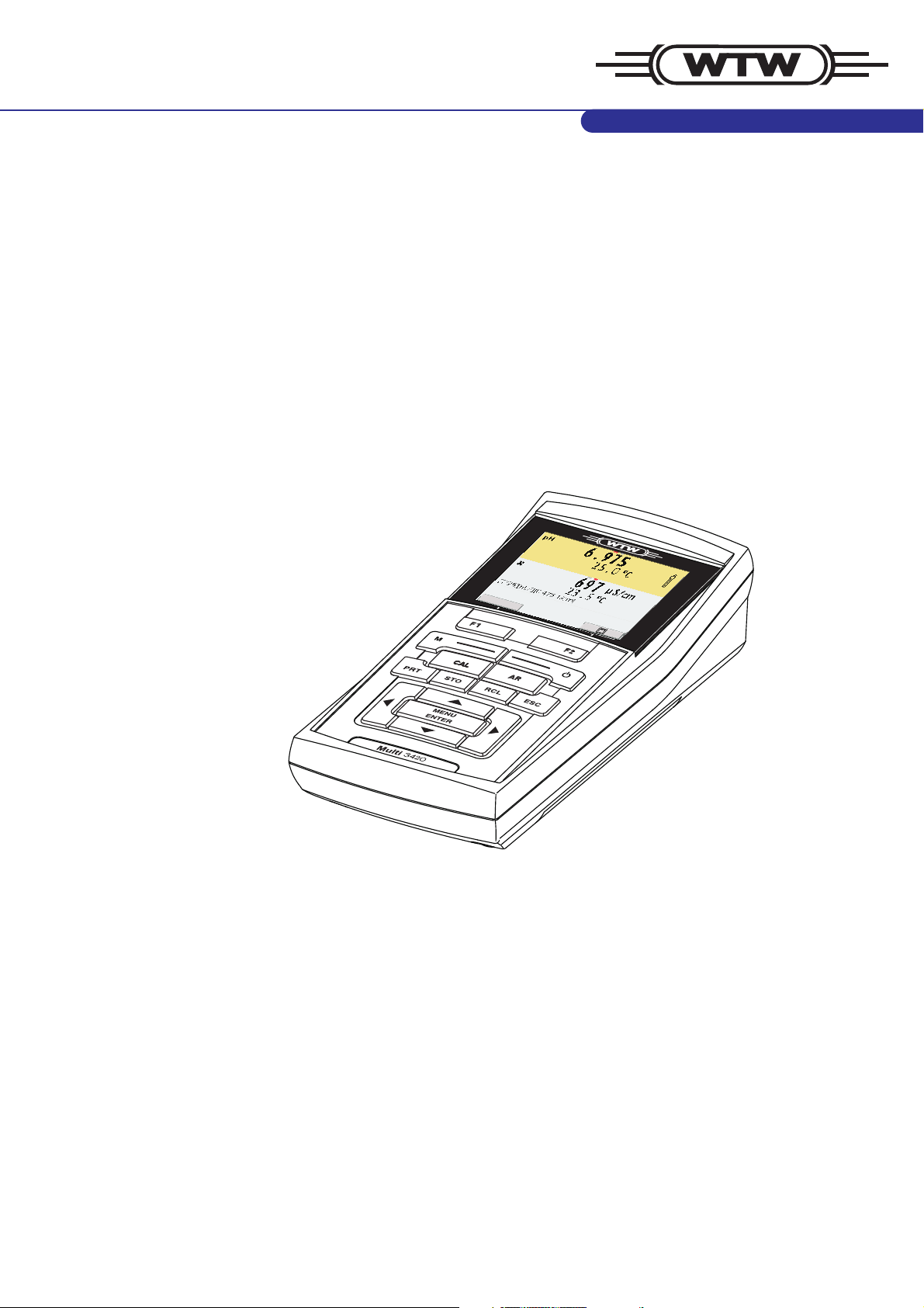
1Overview
The compact, digital precision meter Multi 3420 enables you to carry
out pH measurements, ORP measurements, conductivity measurements and dissolved oxygen (D.O.) measurements quickly and reliably.
The Multi 3420 provides the maximum degree of operating comfort,
reliability and measuring certainty for all applications.
The Multi 3420 supports you in your work with the following functions:
z proven calibration procedures
z automatic stability control (AR),
z automatic sensor recognition,
z CMC (continuous measurement control)
z QSC (sensor quality control).
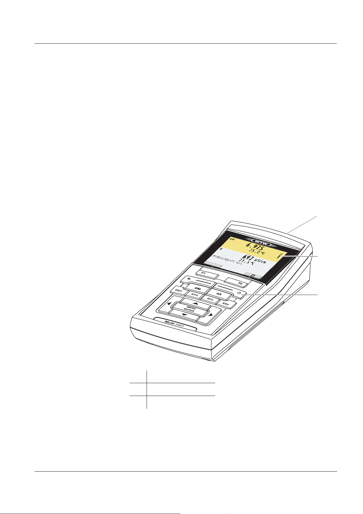
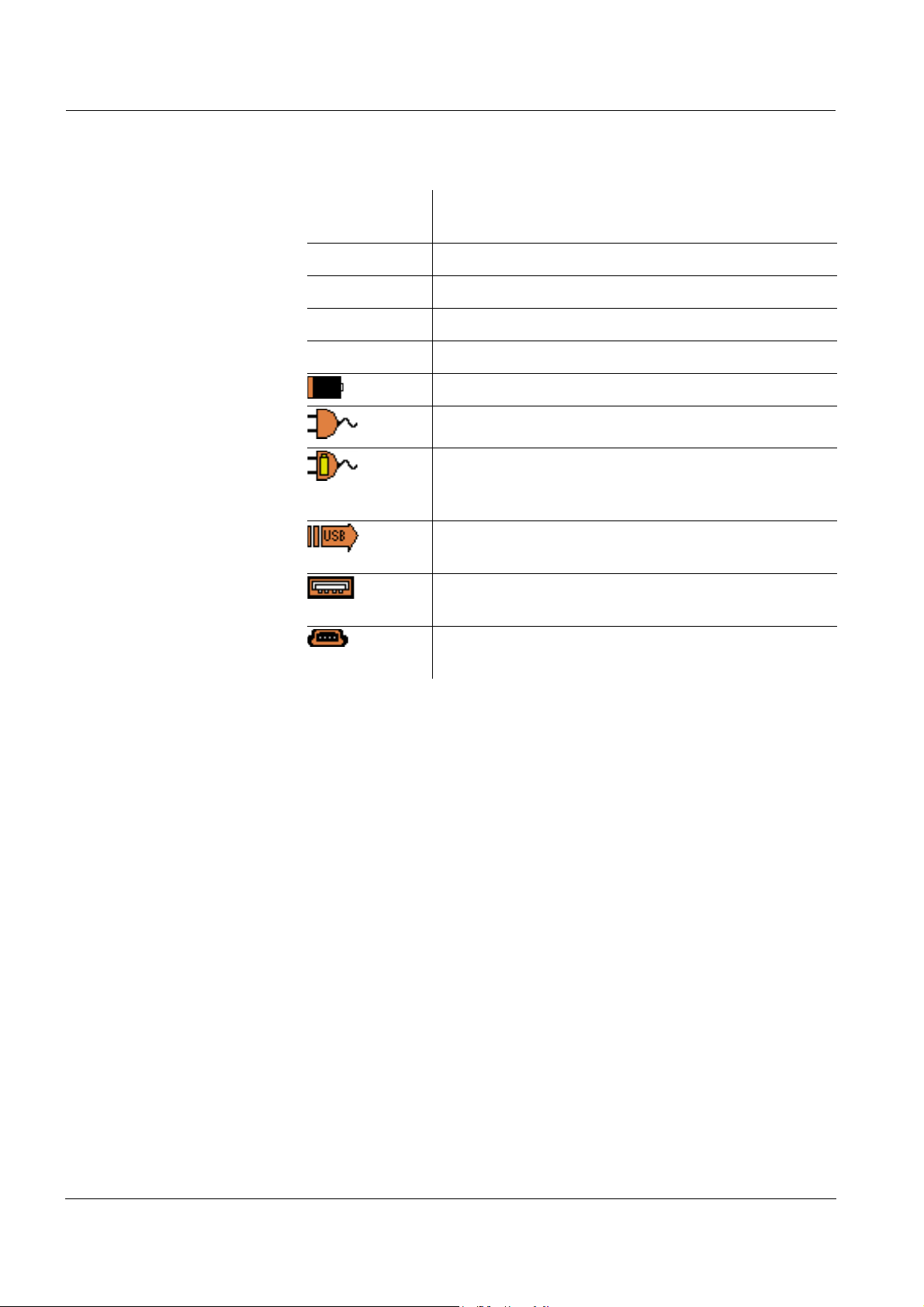
ba75864e11 02/2011
1 Keypad
2 Display
3 Socket field
7
Page 8
Overview Multi 3420
M
pH 3420
F1
F2
ARCAL
PRT ESCRCLSTO
MENU
ENTER
MENU
ENTER
F1
F2
CAL
ARAR
The two USB interfaces (USB-A and USB-B) enable you to:
z Transmit data to
– a USB memory device
–a PC
z Update the meter firmware.
1.1 Keypad
In this operating manual, keys are indicated by brackets <..> .
The key symbol (e.g. <MENU/ENTER>) generally indicates a short
keystroke (under 2 sec) in this operating manual. A long keystroke
(approx. 2 sec) is indicated by the underscore behind the key symbol
<F1>:
<F2>:
(e.g. <MENU/ENTER
Softkeys providing situation dependent functions, e.g.:
<F1>/[Info]: View information on a sensor
_>).
<On/Off>: Switches the meter on or off
<M>: Selects the measured parameter
<CAL>:
<CAL
_>:
Calls up the calibration procedure
Displays the calibration data
<AR> Freezes the measured value (HOLD function)
Switches the AutoRead measurement on or off
8
ba75864e11 02/2011
Page 9
Multi 3420 Overview
MENU
ENTER
MENU
ENTER
PRT
4
3
2
6
7
8
1
5
22.09.2009 08:00
Info
<STO>:
<STO
_>:
<RCL>:
<RCL
_>:
<S><T>:
<W><X>:
<MENU/ENTER>:
<MENU/ENTER
<PRT>
_>
<PRT
_>:
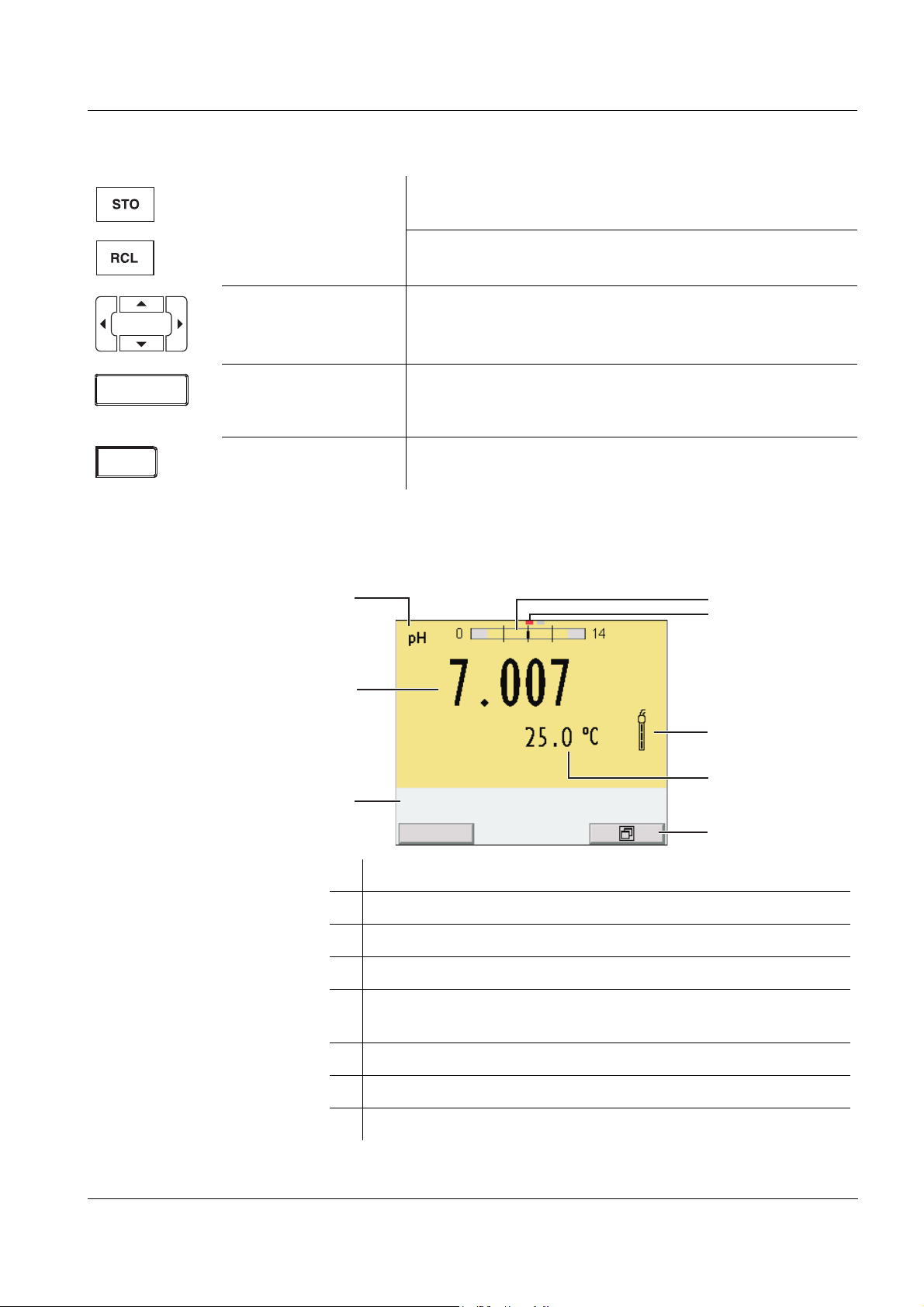
1.2 Display
Saves a measured value manually
Opens the menu for the automatic save function
Displays the manually stored measured values
Displays the automatically stored measured values
Menu control, navigation
Opens the menu for measurement settings / Confirms
entries
Opens the menu for system settings
Outputs stored data to the interface
Outputs displayed data to the interface in intervals
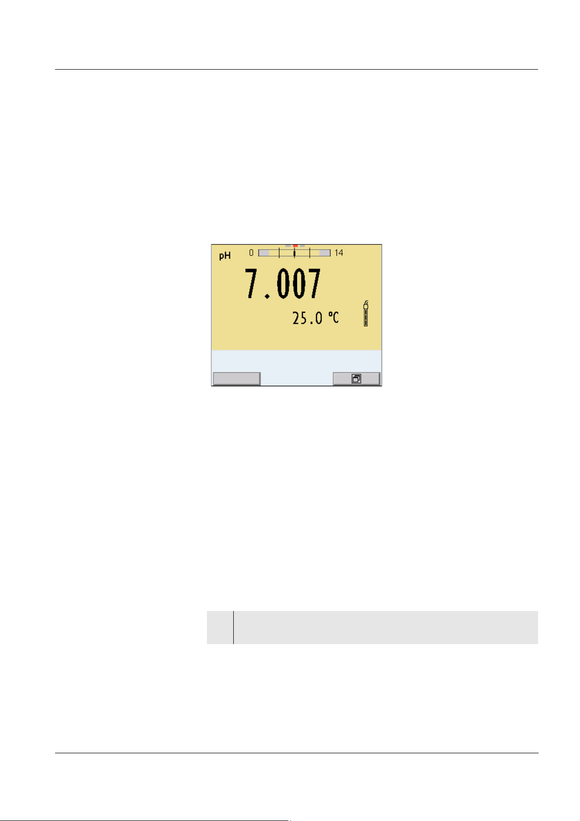
1 Status information
2 Measured value (with unit)
3 Measured parameter
4 Continuous measurement control (CMC function)
5 Channel display:
Plug position of the sensor
6 Sensor symbol (calibration evaluation, calibration interval)
7 Measured temperature (with unit)
8 Softkeys and date + time
ba75864e11 02/2011
9
Page 10
Overview Multi 3420
Function display
indicators
AutoCal
e.g. TEC
Calibration with automatic buffer recognition, e.g.
with the buffer set: Technical buffers
ConCal Calibration with any buffers
Error An error occurred during calibration
AR Stability control (AutoRead) is active
HOLD Measured value is frozen (<AR> key)
Batteries are almost empty
Mains operation
Mains operation with charge function
Batteries are automatically charged in the background.
Data are automatically output to the USB-B interface at intervals
Data are output to the USB-A interface (USB flash
drive)
Power supply via the USB-B interface
Batteries are not being charged
10
ba75864e11 02/2011
Page 11
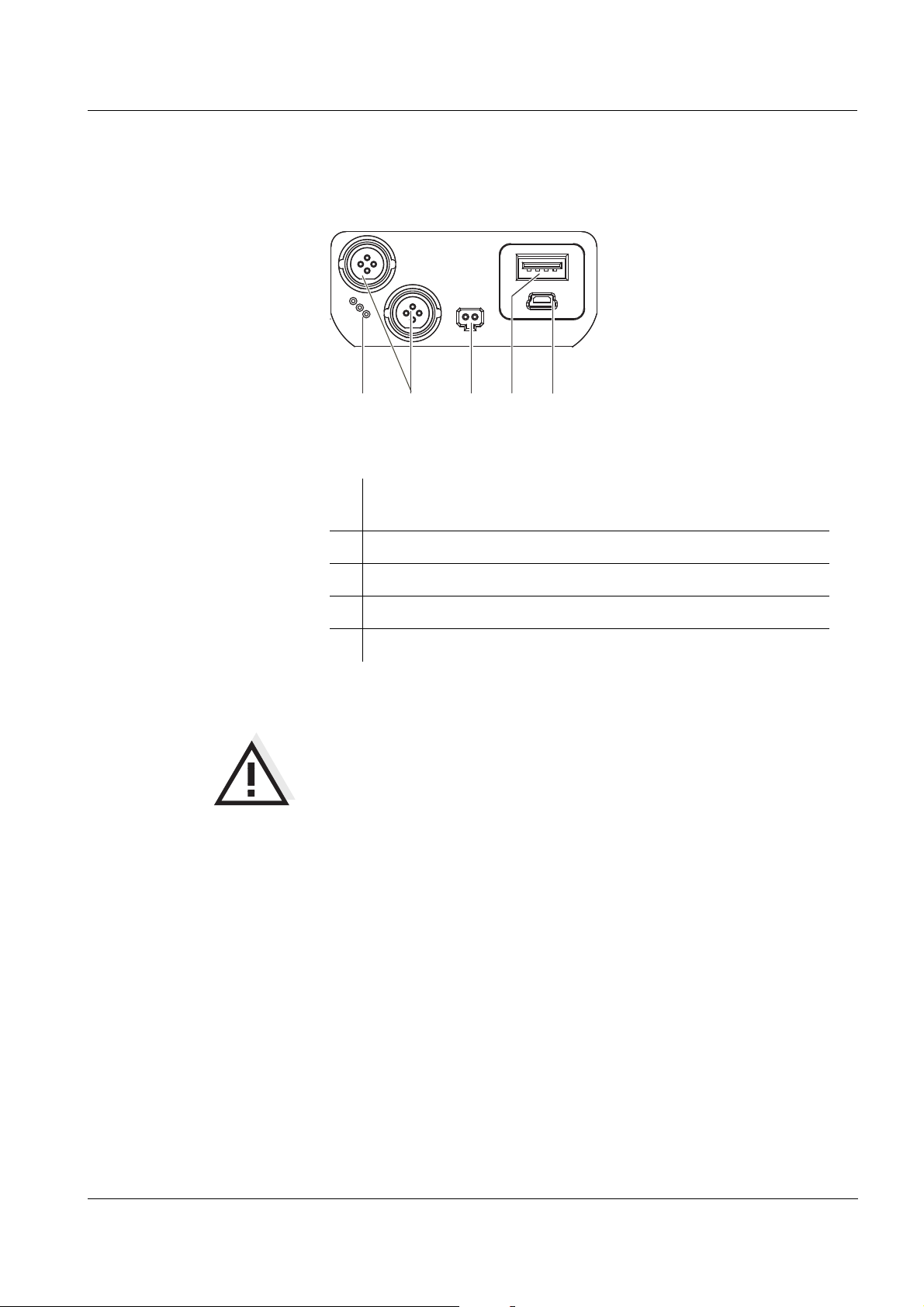
Multi 3420 Overview
5
1
2
3
4
1.3 Socket field
Connectors:
1
Digital sensors
(pH, ORP, conductivity, D.O.)
2 Power pack
3 USB-A (host) interface
4 USB B (device) interface
5 Service interface
CAUTION
Only connect sensors to the meter that cannot return any voltages
or currents that are not allowed (> SELV and > current circuit with
current limiting).
WTW IDS sensors and IDS adapters meet these requirements.
ba75864e11 02/2011
11
Page 12

Overview Multi 3420
1.4 Automatic sensor recognition
The automatic sensor recognition for IDS sensors allows
z to operate an IDS sensor at different meters without recalibration
z to operate different IDS sensors at one meter without recalibration
z to assign measurement data to an IDS sensor
– Measurement datasets are always stored and output with the
sensor name and sensor series number.
z to assign calibration data to an IDS sensor
– Calibration data and calibration history are always stored and
output with the sensor name and sensor series number.
z to activate the correct cell constant for conductivity sensors auto-
matically
z to hide menus automatically that do not concern this sensor
To be able to use the automatic sensor recognition, a meter that supports the automatic sensor recognition (e.g. Multi 3420) and a digital
IDS sensor are required.
In digital IDS sensors, sensor data are stored that clearly identify the
sensor.
The sensor data are automatically taken over by the meter.
1.5 IDS sensors
IDS sensors
z support the automatic sensor recognition
z show only the settings relevant to the specific sensor in the setting
menu
z process signals in the sensor digitally so that precise and interfer-
ence-free measurements are enabled even with long cables
z facilitate to assign a sensor to a measured parameter with differently
colored couplings
z have quick-lock couplings with which to fix the sensors to the meter.
12
Note
Information on available IDS sensors is given on the Internet and in
the WTW catalog, "Laboratory and field instrumentation".
ba75864e11 02/2011
Page 13
Multi 3420 Overview
Sensor data from IDS
sensors
IDS sensors transmit the following sensor data to the meter:
z SENSOR ID
– Sensor name
– Sensor series number
z Calibration data
– Calibration date
– Calibration characteristics
– Calibration interval
– Selected buffer set (IDS pH sensors only)
– Cell constant (IDS conductivity sensors only)
– Calibration history of the last 10 calibrations
z Measurement settings (IDS conductivity sensors only)
– The set measured parameter
– The set reference temperature
– The set temperature coefficient
– The set TDS factor
The calibration data are updated in the IDS sensor after each calibration procedure. A message is displayed while the data are being
updated in the sensor.
Note
In the measured value display, you can display the sensor name and
series number of the selected sensor with the [Info] softkey. You can
then display all further sensor data stored in the sensor with the [More]
softkey.
1.6 IDS adapter for analog sensors
With the aid of an IDS adapter, you can also operate analog sensors
on the Multi 3420. An IDS adapter and analog sensor together behave
like an IDS sensor.
The measuring electronics with the stored adapter data are in the
adapter head. The adapter data correspond to the sensor data.
Note
Information on available IDS adapters is given on the Internet and in
the WTW catalog, "Laboratory and field instrumentation".
Detailed information on the IDS adapter is given in the operating manual of the adapter.
ba75864e11 02/2011
13
Page 14

Overview Multi 3420
14
ba75864e11 02/2011
Page 15
Multi 3420 Safety
2 Safety
This operating manual contains basic instructions that you must follow
during the commissioning, operation and maintenance of the meter.
Consequently, all responsible personnel must read this operating manual before working with the meter.
The operating manual must always be available within the
vicinity of the meter.
Target group The meter was developed for work in the field and in the laboratory.
Thus, we assume that, as a result of their professional training and
experience, the operators will know the necessary safety precautions
to take when handling chemicals.
Safety instructions Safety instructions in this operating manual are indicated by the warn-
ing symbol (triangle) in the left column. The signal word (e.g. "Caution")
indicates the level of danger:
Further notes
WARNING
indicates instructions that must be followed precisely in order to
avoid possibly great dangers to personnel.
CAUTION
indicates instructions that must be followed precisely in order to
avoid the possibility of slight injuries or damage to the meter or
the environment.
Note
indicates notes that draw your attention to special features.
Note
indicates cross-references to other documents, e.g. operating manuals.
ba75864e11 02/2011
15
Page 16
Safety Multi 3420
2.1 Authorized use
The authorized use of the meter consists exclusively of the measurement of the pH, ORP, conductivity and dissolved oxygen in a field and
laboratory environment.
The technical specifications as given in chapter 7 T
ECHNICAL DATA must
be observed. Only the operation and running of the meter according to
the instructions given in this operating manual is authorized.
Any other use is considered unauthorized.
2.2 General safety instructions
This meter is constructed and tested in compliance with the IEC 1010
safety regulations for electronic measuring instruments.
It left the factory in a safe and secure technical condition.
Function and
operational safety
The smooth functioning and operational safety of the meter can only be
guaranteed if the generally applicable safety measures and the specific
safety instructions in this operating manual are followed during operation.
The smooth functioning and operational safety of the meter can only be
guaranteed under the environmental conditions that are specified in
chapter 7 T
ECHNICAL DATA.
If the meter was transported from a cold environment to a warm environment, the formation of condensate can lead to the faulty functioning
of the meter. In this event, wait until the temperature of the meter
reaches room temperature before putting the meter back into operation.
CAUTION
The meter is only allowed to be opened by authorized personnel.
16
ba75864e11 02/2011
Page 17
Multi 3420 Safety
Safe operation If safe operation is no longer possible, the meter must be taken out of
service and secured against inadvertent operation!
Safe operation is no longer possible if the meter:
z has been damaged in transport
z has been stored under adverse conditions for a lengthy period of
time
z is visibly damaged
z no longer operates as described in this manual.
If you are in any doubt, please contact the supplier of the meter.
Obligations of the
purchaser
The purchaser of this meter must ensure that the following laws and
guidelines are observed when using dangerous substances:
z EEC directives for protective labor legislation
z National protective labor legislation
z Safety regulations
z Safety datasheets of the chemical manufacturers.
CAUTION
In addition to the safety instructions mentioned here, also follow
the safety instructions of the sensors used.
The operating manuals of the sensors are available on the supplied CD and on the Internet under www.WTW.com.
ba75864e11 02/2011
17
Page 18

Safety Multi 3420
18
ba75864e11 02/2011
Page 19

Multi 3420 Commissioning
3 Commissioning
3.1 Scope of delivery
z Meter Multi 3420
z 4 NiMH rechargeable batteries 1.2 V Mignon type AA
z USB cable (A plug on mini B plug)
z Power pack
z Short instructions
z Detailed operating manual (4 languages)
z CD-ROM
3.2 Power supply
The Multi 3420 is supplied with power in the following ways:
z Battery operation with NiMh rechargeable batteries
z Mains operation with the supplied power pack.
The NiMh rechargeable batteries are automatically charged while
the power pack is connected.
z USB operation via a connected USB-B cable.
The inserted NiMh rechargeable batteries are not charged
3.3 Initial commissioning
Perform the following activities:
z Insert the rechargeable batteries and charge them
z Connect the power pack (mains operation / battery charging)
z Switch on the meter
z Set the date and time
3.3.1 Inserting the rechargeable batteries
ba75864e11 02/2011
1 Unscrew the two screws (1) on the underside of the meter.
2 Open the battery compartment (2) on the underside of the
meter.
19
Page 20
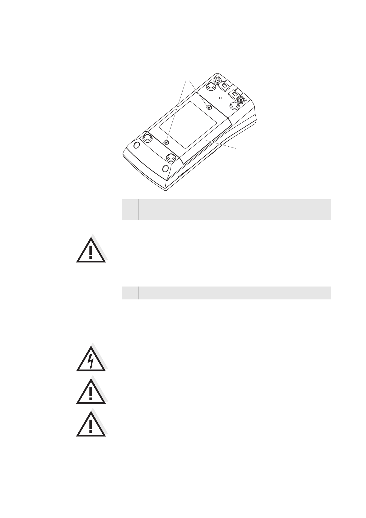
Commissioning Multi 3420
2
1
3 Place four rechargeable batteries (type Mignon AA) in the bat-
tery compartment.
CAUTION
Make sure that the poles of the rechargeable batteries are positioned correctly.
The
± signs on the batteries must correspond to the ± signs in the
battery compartment.
4 Close the battery compartment (2) and tighten the screws (1).
3.3.2 Connecting the power pack / charging the batteries
CAUTION
The line voltage at the operating site must lie within the input voltage range of the original power pack (see section 7.1).
CAUTION
Use original power packs only (see section 7.1).
CAUTION
The batteries in the battery compartment are automatically
charged when the power pack is connected.
Make sure that only NiMH rechargeable batteries are in the battery
compartment. The charging process is optimized for NiMH rechargeable batteries. Other battery types can cause damage during the charging process.
20
ba75864e11 02/2011
Page 21
Multi 3420 Commissioning
1 Connect the plug of the power pack to the socket for the power
pack on the Multi 3420.
2 Connect the original power pack to an easily accessible power
outlet.
During mains operation, one of the following symbols is displayed:
:
Mains operation with charge function
Batteries are automatically charged in the background.
:
Mains operation
Note
Charge the batteries completely prior to putting the meter into operation
for the first time. The charging process takes approx. 10 hours. The
symbol is displayed if the batteries are nearly discharged.
3.3.3 Switching on the meter
1 Press the <On/Off> key.
The meter performs a self-test.
The display shows the manufacturer's logo while the self-test
is being performed.
2 Connect the sensor.
The meter switches to the measuring mode (measured value
display).
Note
The meter has an energy saving feature to avoid unnecessary power
consumption during battery operation.
The energy saving feature switches off the meter during battery operation if no key is pressed during the adjusted interval. (How to set the
switch-off interval, see section 4.4).
The switch-off interval of the energy saving feature is not active when
the meter is supplied with power via the power pack or the USB-B
cable.
ba75864e11 02/2011
21
Page 22

Commissioning Multi 3420
3.3.4 Setting the date and time
3 See section 4.3.5
22
ba75864e11 02/2011
Page 23
Multi 3420 Operation
22.11.2010 08:00Info
4 Operation
4.1 Switching on the meter
Switching on Press the <On/Off> key.
The meter performs a self-test.
The display shows the manufacturer's logo while the self-test is being
performed.
If a sensor is connected, the measured value display appears.
Switching off Press the <On/Off> key.
4.2 Login with a user name
After activation of the user administration by the administrator, measurements are only possible after login with a user name. The user
name is documented with the measured values and in records.
All user names entered by the administrator are listed in the User name
menu. The administrator determines for each user whether or not a
password is required for login to the meter.
If the Password menu item is grayed out, no password is required for
login.
1 Switch on the meter with <On/Off>.
The Login dialog box appears.
ba75864e11 02/2011
23
Page 24
Operation Multi 3420
User name Admin
Password ####
Change password
Login
22.09.2009 08:00
2 Using <S><T>, enter the Benutzername menu item and con-
firm with <MENU/ENTER>.
The user name is highlighted.
3Using <S><T>, select a user name and confirm with <MENU/
ENTER>.
Note
The login is done immediately if no password is required.
If a sensor is connected the measured value display appears.
4 If a password is required:
Using <S><T>, enter the Password menu item and confirm
with <MENU/ENTER>.
Note
The user specifies the password when he or she first logs in with a user
name.
A valid password consists of 4 digits.
The user can change the password with the next login.
5 Change the digit of the highlighted position with <S><T>.
Go to the next digit of the password with <W><X>.
When the password was completely entered, confirm with
<MENU/ENTER>.
The login takes place. If a sensor is connected the measured
value display appears.
24
ba75864e11 02/2011
Page 25
Multi 3420 Operation
Changing the password If the administrator has set up the access with password protection:
1 Switch on the meter with <On/Off>.
The Login dialog box appears.
2 Using <S><T>, enter the Benutzername menu item and con-
firm with <MENU/ENTER>.
The user name is highlighted.
3 Using <S><T>, select a user name and confirm with <MENU/
ENTER>.
4 Using <S><T>, enter the Change password menu item and
confirm with <MENU/ENTER>.
5 Enter the old password in the Password box with <S><T>
and <W><X> and confirm with <MENU/ENTER>.
6 Enter the new password in the New password box with
<S><T> and <W><X> and confirm with <MENU/ENTER>.
The password is changed.
The login takes place. If a sensor is connected the measured
value display appears.
Forgotten the
password?
Contact the administrator.
ba75864e11 02/2011
25
Page 26

Operation Multi 3420
4.3 General operating principles
This section contains basic information on the operation of the
Multi 3420.
Operating elements,
display
Operating modes,
navigation
An overview of the operating elements and the display is given in section 1.1 and section 1.2.
An overview of the operating modes and navigation of the Multi 3420 is
given in section 4.3.1 and section 4.3.3.
4.3.1 Operating modes
The meter has the following operating modes:
z Measuring
The measurement data of the connected sensors is shown in the
measured value display
z Calibration
The course of a calibration with calibration information, functions
and settings is displayed
z Storage in memory
The meter stores measuring data automatically or manually
z Data transmission
The meter transmits measuring data and calibration records to a
USB-B interface automatically or manually.
z Setting
The system menu or a sensor menu with submenus, settings and
functions is displayed
26
ba75864e11 02/2011
Page 27
Multi 3420 Operation
22.11.2010 08:00Info
30.09.2009 08:00Info
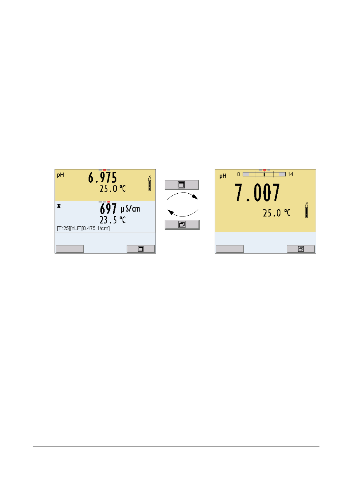
4.3.2 Display of several sensors in measuring mode
The measured values of the connected sensors can be displayed in the
following ways:
z Clear display of all connected sensors
z Detailed display of one sensor
(e.g. incl. CMC feature with pH sensors)
With the softkey you can very easily switch between the two display
types. The suitable softkey is displayed, depending on the operating
situation.
ba75864e11 02/2011
27
Page 28
Operation Multi 3420
General
Interface
Clock function
Service information
Reset
System
22.09.2009 08:00
4.3.3 Navigation
Measured value display In the measured value display, you can
z use <S><T> to select one of several connected sensors. The
selected sensor is displayed with a colored background.
The following actions / menus refer to the selected sensor
z open the menu for calibration and measurement settings with
<MENU/ENTER> (short
keystroke)
z open the system menu with the sensor-independent settings by
pressing <MENU/ENTER>Storage & config for a <MENU/
ENTER
_>long keystroke, approx. 2 s).
z change the display in the selected measuring window (e. g. pH ><−
mV) by pressing <M>.
Menus and dialogs The menus for settings and dialogs in procedures contain further sub-
menus. The selection is made with the <S><T> keys. The current
selection is displayed with a frame.
z Submenus
The name of the submenu is displayed at the upper edge of the
frame. Submenus are opened by confirming with <MENU/ENTER>.
Example:
z Settings
Settings are indicated by a colon. The current setting is displayed on
the right-hand side. The setting mode is opened with <MENU/
ENTER>. Subsequently, the setting can be changed with <S><T>
and <MENU/ENTER>. Example:
28
ba75864e11 02/2011
Page 29
Multi 3420 Operation
Language: Deutsch
Acoustic signal: Off
Volume 9
Illumination: On
Brightness: 12
Switchoff time: 1 h
Temperature unit: °C
Stability control
: On
General
22.09.2009 08:00
Calibration record
Calibration data storage
Buffer: TEC
Single-point calibration: Yes
Calibration interval: 7 d
Unit for slope: mV/pH
[i] 2.00 4.01 7.00 10.01
pH
22.09.2009 08:00
Calibration record
Calibration data storage
Buffer: TEC
Single-point calibration: Yes
Calibration interval: 7 d
Unit for slope: mV/pH
[i] 2.00 4.01 7.00 10.01
pH
22.09.2009 08:00
z Functions
Functions are designated by the name of the function. They are
immediately carried out by confirming with <MENU/ENTER>. Example: Display the Calibration record function.
Messages Information is marked by the [
ba75864e11 02/2011
i
] symbol. They cannot be selected.
Example:
Note
The principles of navigation are explained in the two following sections
by reference of examples:
z Setting the language (section 4.3.4)
z Setting the date and time (see section 4.3.5).
29
Page 30
Operation Multi 3420
22.11.2010 08:00Info
System
Data storage
Storage & config
22.09.2009 08:00
4.3.4 Example 1 on navigation: Setting the language
1 Press the <On/Off> key.
The measured value display appears.
The instrument is in the measuring mode.
2 Open the Storage & config menu with <MENU/ENTER_>.
The instrument is in the setting mode.
3 Select the System submenu with <S><T>.
The current selection is displayed with a frame.
4 Open the System submenu with <MENU/ENTER>.
30
ba75864e11 02/2011
Page 31

Multi 3420 Operation
General
Interface
Clock function
Service information
Reset
System
22.09.2009 08:00
Language: Deutsch
Acoustic signal: Off
Illumination: On
Kontrast: 50 %
Switchoff time: 1 h
General
22.09.2009 08:00
Language: Deutsch
Acoustic signal: Off
Illumination: On
Brightness: 50 %
Switchoff time: 1 h
General
22.09.2009 08:00
5 Select the General submenu with <S><T>.
The current selection is displayed with a frame.
6 Open the General
submenu with <MENU/ENTER>.
7 Open the setting mode for the Language with <MENU/
ENTER>.
ba75864e11 02/2011
31
Page 32

Operation Multi 3420
8 Select the required language with <S><T>.
9 Confirm the setting with <MENU/ENTER>.
The meter switches to the measuring mode.
The selected language is active.
4.3.5 Example 2 on navigation: Setting the date and time
The measuring instrument has a clock with a date function. The date
and time are indicated in the status line of the measured value display.
When storing measured values and calibrating, the current date and
time are automatically stored as well.
The correct setting of the date and time and date format is important for
the following functions and displays:
Setting the date, time
and date format
z Current date and time
z Calibration date
z Identification of stored measured values.
Therefore, check the time at regular intervals.
Note
After a fall of the supply voltage (empty batteries), the date and time are
reset to 01.08.2009 00, 00:00 hours.
The date format can be switched from the display of day, month, year
(dd.mm.yy) to the display of month, day, year (mm/dd/yy or mm.dd.yy).
1 In the measured value display:
Open the Storage & config menu with <MENU/ENTER
The instrument is in the setting mode.
2 Select and confirm the System / Clock function menu with
<S><T> and <MENU/ENTER>.
The setting menu for the date and time opens up.
_>.
32
ba75864e11 02/2011
Page 33

Multi 3420 Operation
Date format: dd.mm.yy
Date: 30.09.2009
Time: 14:53:40
Clock function
22.09.2009 08:00
3 Select and confirm the Time menu with <S><T> and <MENU/
ENTER>.
The hours are highlighted.
4 Change and confirm the setting with <S><T> and <MENU/
ENTER>.
The minutes are highlighted.
5 Change and confirm the setting with <S><T> and <MENU/
ENTER>.
The seconds are highlighted.
6 Change and confirm the setting with <S><T> and <MENU/
ENTER>.
The time is set.
7 If necessary, set the Date and Date format. The setting is made
similarly to that of the time.
8 If necessary, select and set the Date with <S><T> and
<MENU/ENTER>.
9 To make further settings, switch to the next higher menu level
with <ESC>.
or
Switch to the measured value display with <M>.
The instrument is in the measuring mode.
ba75864e11 02/2011
33
Page 34

Operation Multi 3420
4.4 Sensor-independent settings
The Storage & config menu includes the following settings:
z System (see section 4.4.1).
z Data storage (see section 4.4.2)
4.4.1 System
Overview The following sensor-independent meter characteristics can be
adjusted in the Storage & config/System menu:
z Menu language
z Beep on keystroke
z Loudness of the beep
z Illumination
z Brightness
z Interval of the automatic switchoff
z Data interface
z Clock and date function
z Reset of all sensor-independent system settings to the default con-
dition
Settings To open the Storage & config menu, press the <MENU/ENTER
in the measured value display. After completing the settings, switch to
the measured value display with <M>.
Default settings are printed in bold.
Menu item Setting Description
System / General / Language Deutsch
English
(more)
System /
General /
Acoustic signal
Beep 1
Beep 2
off
Selects the menu language
Switches on/off the beep on
keystroke
_> key
34
System / General / Volume 0 ... 5 ... 10 Changes the loudness of the
beep
System / General / Illumination Auto
on
System / General / Brightness 0 ... 10 ... 22 Changes the display bright-
System / General / Switchoff time 10 min ... 1h ... 24 h Adjusts the switch-off time
Switches the display illumination on/off
ness
ba75864e11 02/2011
Page 35

Multi 3420 Operation
Menu item Setting Description
System / General / Temperature
unit
°C
°F
System / General / Stability control on
off
System / Interface / USB Host on
off
System / Interface / Baud rate 1200, 2400, 4800,
9600, 19200
Temperature unit,
degrees Celsius or degrees
Fahrenheit.
All temperatures are displayed
with the selected unit.
Switches on or off the automatic stability control during
measurement (see section
4.4.3)
Switches on or off the USB
Host interface.
You can switch off the power
supply of the USB Host interface to extend the operating
time of the batteries.
The USB Host interface has to
be switched on in order to
transfer data to a USB memory
device.
Baud rate of the USB Device
interface
System / Interface / Output format ASCII
CSV
Output format for data transmission
For details, see section 4.12
System / Interface / Decimal separator
Dot (xx.x)
Comma (xx,x)
Decimal separator
System / Interface / Output header Output of a header for Output
format: CSV
System /Clock function Date format
Date
Settings of time and date.
For details, see section 4.3.5
Time
System /Service information Hardware version and software
version of the meter are displayed.
System /Reset - Resets the system settings to
the default values.
For details, see section 4.13.2
ba75864e11 02/2011
35
Page 36

Operation Multi 3420
4.4.2 Data storage
This menu contains all functions to display, edit and erase stored measured values.
Note
Detailed information on the storage functions of the Multi 3420 is given
in section 4.11.
4.4.3 Automatic Stability control
The automatic Stability control (AutoRead) function continuously
checks the stability of the measurement signal. The stability has a considerable impact on the reproducibility of measured values.
You can activate or switch off the automatic Stability control function
(see section 4.4).
The measured parameter flashes on the display
z as soon as the measured value is outside the stability range
z when you switch over between the measured parameters with <M>.
z when the automatic Stability control is switched off.
4.4.4 Automatic switch-off
The instrument has an automatic switchoff function in order to save the
batteries (see section 4.4.1). The automatic switchoff switches off the
measuring instrument if no key is pressed for an adjustable period.
The automatic switchoff is not active
z if the power pack is connected
z if a USB-B cable is connected
z if the Automatic data storage function is active, or with automatic
data transmission
36
4.4.5 Display illumination
The meter automatically switches the display illumination to energy
saving mode if no key is pressed for 20 seconds.
After a further 60 seconds, the meter switches off the display illumination completely.
The illumination is switched on with the next keystroke again.
You can also generally switch on the display illumination (see section
4.4.1).
ba75864e11 02/2011
Page 37

Multi 3420 Operation
22.11.2010 08:00
Info
22.11.2010 08:00More
4.5 Sensor info
You can display the current sensor data and sensor settings of a connected sensor at any time. The sensor data are available in the measured value display with the [Info] softkey.
1 In the measured value display:
Display the sensor data (sensor name, series number) with
[Info].
2 Display further sensor data (settings) with [More].
ba75864e11 02/2011
37
Page 38

Operation Multi 3420
30.09.2009 08:00
Man. temperature: 25 °C
pH resolution 0.001
mV resolution 0.1
Buffer TEC
Calibration interval 7d
Unit for slope mV/pH
QSC:
SenTix 940
B092500013
22.11.2010 08:00Info
Channel display
Display of the plug position
for the respective parameter
The red bar indicates for
each connected sensor to
which plug position of the
meter it is connected.
4.6 Channel display
The Multi 3420 manages the connected sensors and displays which
sensor is plugged to which connection.
38
ba75864e11 02/2011
Page 39

Multi 3420 Operation
4.7 pH value
4.7.1 General information
You can measure the following parameters:
z pH value [ ]
z Sensor voltage [mV]
Note
The sensor connection and the USB-B (device) interface are galvanically isolated. This facilitates interference-free measurements also in
the following cases:
z Measurement in grounded test samples
z Measurement in one test sample with several sensors connected to
one Multi 3420
Temperature
measurement
For reproducible pH measurements, it is essential to measure the temperature of the test sample. IDS sensors measure the temperature with
a temperature sensor integrated in the IDS sensor.
When operating a sensor without integrated temperature sensor, e.g.
via an IDS pH adapter, you have the following options to determine the
temperature of the measuring solution:
z Temperature measurement via the integrated temperature sensor of
an IDS sensor.
When the measured temperature value is taken from an IDS sensor
the [TP
↑
] status indicator is displayed in the measuring window of
the IDS pH adapter. In the measuring window of the IDS sensor providing the measured temperature value the [TP
↓
] status indicator is
displayed.
z Manual determination and input of the measured temperature value.
Note
The settings for the temperature can be adjusted in the menu for calibration and measurement settings (siehe section 4.7.3).
Preparatory activities Perform the following preparatory activities when you want to measure:
ba75864e11 02/2011
1 Connect the IDS pH sensor to the meter.
The pH measuring window is displayed.
2 If necessary, select the measured parameter with <M>.
3 If necessary, calibrate or check the IDS pH sensor.
39
Page 40

Operation Multi 3420
22.11.2010 08:00Info
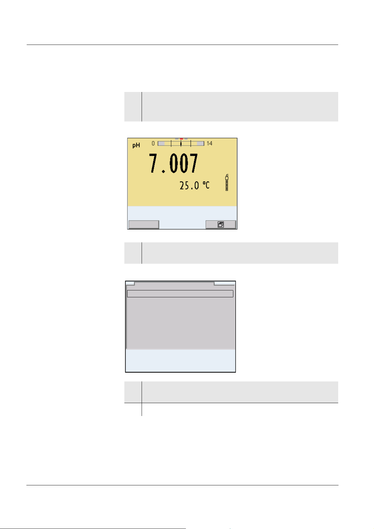
4.7.2 Measuring the pH value
1 Perform the preparatory activities according to section 4.7.1.
2 Immerse the IDS pH sensor in the test sample.
Stability control
(AutoRead )
3 Select the pH or mV display with <M>.
The stability control function (AutoRead) continually checks the stability
of the measurement signal. The stability has a considerable impact on
the reproducibility of measured values. The display of the measured
parameter flashes until a stable measured value is available.
You can start the Stability control manually at any time, irrespective of
the setting for automatic Stability control (see section 4.4.3) in the Sys-
tem menu.
1 Freeze the measured value with <AR>.
The [HOLD] status indicator is displayed.
2Using <MENU/ENTER>, activate the Stability control function
manually.
The [AR] status indicator appears while the measured value is
assessed as not stable. A progress bar is displayed and the
display of the measured parameter flashes.
The [HOLD][AR] status indicator appears as soon as a stable
measured value is recognized. The progress bar disappears
and the display of the measured parameter stops flashing.
The current measurement data is output to the interface. Measurement data meeting the stability control criterion is marked
by AR.
40
ba75864e11 02/2011
Page 41

Multi 3420 Operation
Note
You can prematurely terminate the Stability control function manually
with <MENU/ENTER> at any time. If the Stability control function is pre-
maturely terminated, the current measurement data are output to the
interface without the AutoRead info.
3 Release the frozen measured value again with <AR> or <M>.
The [AR] status display disappears. The display switches back
to the previous indication.
Criteria for a stable
measured value
The Stability control function checks whether the measured values are
stable within the monitored time interval.
Measured
Time interval Stability in the time interval
parameter
pH value 15 seconds
Temperature 15 seconds
Δ pH: Better than 0.01
Δ T (° C): Better than 0.02
The minimum duration until a measured value is assessed as stable is
the monitored time interval. The actual duration is mostly longer.
ba75864e11 02/2011
41
Page 42

Operation Multi 3420
4.7.3 Settings for pH measurements
Overview The following settings are possible for pH measurements:
z Calibration record (display)
z Calibration data storage (display)
z Calibration interval
z Buffers for calibration
z Single-point calibration
z Unit for slope
z Resolution
Settings The settings are made in the menu for calibration and measurement
settings of the pH/ORP measurement. To open the settings, display the
required parameter in the measured value display and press the
<MENU/ENTER> key. After completing the settings, switch to the measured value display with <M>.
Default settings are printed in bold.
Menu item Possible setting Description
Calibration /Calibration record - Displays the calibration record of the last cal-
ibration
Calibration /Calibration data
storage
Calibration / Calibration data
storage / Copy to USB flash
- Displays the last calibration records (max.
10)
- Outputs the calibration data storage to a connected USB flash drive
drive
Calibration / Calibration data
storage / Output to RS232/USB
Calibration /Buffer TEC
- Outputs the calibration data storage to the
interface
Buffer sets to be used for pH calibration.
NIST/DIN
ConCal
For further buffers and details, see section
4.7.4.
...
Calibration /Single-point calibration
yes
no
Quick calibration with 1 buffer
Calibration /Calibration interval 1 ... 7 ... 999 d Calibration interval for the IDS pH sensor (in
days).
42
The meter reminds you to calibrate regularly
by the flashing sensor symbol in the measuring window.
ba75864e11 02/2011
Page 43

Multi 3420 Operation
Menu item Possible setting Description
Calibration /Unit for slope mV/pH
%
Unit of the slope.
The % display refers to the Nernst slope of
-59.2 mV/pH (100 x determined slope/Nernst
slope).
QSC /First calibration - Starts the initial calibration with QSC buffers.
This menu item is only available as long as
no initial calibration was carried out with the
connected IDS sensor.
QSC /Record of first calibration - Displays the calibration record of the QSC ini-
tial calibration
QSC /Control calibration - Starts the control calibration with QSC buf-
fers.
This menu item is only available if an initial
calibration was carried out with the connected IDS sensor.
Man. temperature -25 ... +25 ...
+130 °C
Entry of the manually determined temperature
This menu item is only available if an IDS
adapter and is connected.
Alternative temperature on
off
Takes the measured temperature value from
an IDS sensor.
This menu item is only available if an IDS
adapter and an IDS sensor with temperature
sensor are connected.
pH resolution 0.001
Resolution of the pH display
0.01
0.1
mV resolution 0.1
Resolution of the mV display
1
Reset - Resets all sensor settings to the delivery con-
dition (see section 4.13.1)
ba75864e11 02/2011
43
Page 44

Operation Multi 3420
4.7.4 pH calibration
Why calibrate? During the operation of an IDS pH sensor, the zero point (asymmetry)
and
slope of the sensor change with time.As a result, an inexact measured
value is displayed. Calibration determines the current values of the
zero point and slope of the pH sensor and stores them in the measuring
instrument.
Thus, you should calibrate at regular intervals.
When do you have to
calibrate?
Buffer sets for
calibration
z When the calibration interval has expired
You can use the buffer sets quoted in the table for an automatic calibration. The pH values are valid for the specified temperature values. The
temperature dependence of the pH values is taken into consideration
during the calibration.
No. Buffer set * pH values at
1 ConCal Any Any
2 NIST/DIN
DIN buffers according to DIN 19266
and NIST Traceable Buffers
1.679
4.006
6.865
25 °C
9.180
12.454
3 TEC
WTW Technical buffers
2.000
4.010
25 °C
7.000
10.011
4 Merck 1* 4.000
20°C
7.000
9.000
44
5 Merck 2 * 1.000
6.000
8.000
13.000
6 Merck 3 * 4.660
6.880
9.220
7 Merck 4 * 2.000
4.000
7.000
10.000
ba75864e11 02/2011
20°C
20°C
20°C
Page 45

Multi 3420 Operation
No. Buffer set * pH values at
8 Merck 5 * 4.010
7.000
10.000
9 DIN 19267 1.090
4.650
6.790
9.230
10 Mettler Toledo US * 1.679
4.003
7.002
10.013
11 Mettler Toledo EU * 1.995
4.005
7.002
9.208
12 Fisher 1* 2.007
4.002
7.004
10.002
13 Fluka BS * 4.006
6.984
8.957
25 °C
25 °C
25 °C
25 °C
25 °C
25 °C
14 Radiometer * 1.678
4.005
7.000
9.180
15 Baker * 4.006
6.991
10.008
16 Metrohm * 3.996
7.003
8.999
17 Beckman * 4.005
7.005
10.013
18 Hamilton DC * 4.005
7.002
10.013
19 Precisa * 3.996
7.003
8.999
25 °C
25 °C
25 °C
25 °C
25 °C
25 °C
ba75864e11 02/2011
45
Page 46

Operation Multi 3420
No. Buffer set * pH values at
20 Reagecon TEC * 2.000
25 °C
4.010
7.000
10.000
21 Reagecon 20 * 2.000
20°C
4.000
7.000
10.000
13.000
22 Reagecon 25 * 2.000
25 °C
4.000
7.000
10.000
13.000
23 Riedel-de Haen * 2.000
20°C
4.000
7.000
10.000
* Brand names or trade names are trademarks of their respective
owners protected by law.
Note
The buffers are selected in the menu, pH / <MENU/ENTER> / Calibra-
tion / Buffer (see section 4.7.3).
46
ba75864e11 02/2011
Page 47

Multi 3420 Operation
Calibration points Calibration can be performed using one to five buffer solutions in any
order (single-point to five-point calibration). The meter determines the
following values and calculates the calibration line as follows:
Determined
Displayed calibration data
values
1-point Asy z Zero point = Asy
z Slope = Nernst slope
(-59.2 mV/pH at 25 °C)
2-point Asy
Slp.
3-point to
5-point
Asy
Slp.
z Zero point = Asy
z Slope = Slp.
z Zero point = Asy
z Slope = Slp.
The calibration line is calculated
by linear regression.
Note
You can display the slope in the units, mV/pH or % (see section 4.7.3).
Stability control The calibration procedure automatically activates the stability control
function. The current measurement with stability control can be terminated at any time (accepting the current value).
Calibration record The new calibration values are displayed when a calibration procedure
is completed.
Display calibration data
and output to interface
You can have the data of the last calibration displayed (see section
4.7.8). Subsequently, you can transmit the displayed calibration data to
the interface, e. g. to a PC, with the <PRT> key.
Note
The calibration record is automatically transmitted to the interface after
calibrating.
ba75864e11 02/2011
47
Page 48

Operation Multi 3420
Multi 3420
Ser. no. 09250023
CALIBRATION pH
Calibration date 31.07.2009 16:13:33
SenTix 940
Ser. no. B092500013
TEC
Buffer 1 4.01
Buffer 2 7.00
Buffer 3 10.01
Voltage 1 184.0 mV 24.0 °C
Voltage 2 3.0 mV 24.0 °C
Voltage 3 -177.0 mV 24.0 °C
Slope -60.2 mV/pH
Asymmetry 4.0 mV
Sensor +++
etc...
Sample record
Calibration evaluation After calibrating, the meter automatically evaluates the calibration. The
zero point and slope are evaluated separately. The worse evaluation of
both is taken into account. The evaluation appears on the display and
in the calibration record.
Display Calibration
Clean the IDS sensor according to the
sensor operating manual
Error Error
Eliminate the error according to chapter
6 W
HAT TO DO IF...
record
Zero point
[mV]
Slope
[mV/pH]
+++ -15 ... +15 -60.5 ... -58
++ -20 ... +20 -58 ... -57
+ -25 ... +25 -61 ... -60.5
or
-57 ... -56
- -30 ... +30 -62 ... -61
or
-56 ... -50
< -30 or
> 30
... -62 or
... -50
48
Note
For pH IDS sensors, you can optionally enable a more finely graded
calibration evaluation (QSC) (see section 4.7.10).
ba75864e11 02/2011
Page 49

Multi 3420 Operation
Preparatory activities Perform the following preparatory activities when you want to calibrate:
1 Connect the IDS pH sensor to the meter.
The pH measuring window is displayed.
2 Keep the buffer solutions ready.
4.7.5 Calibration interval
The calibration evaluation is displayed as a sensor symbol.
After the QSC function has been enabled the sensor symbol is
replaced by the QSC color scale (see section 4.7.10).
After the specified calibration interval has expired, the sensor symbol
or the QSC color scale flashes. It is still possible to measure.
Setting the calibration
interval
Note
To ensure the high measuring accuracy of the measuring system, calibrate after the calibration interval has expired.
The calibration interval is set to 7 days (d7) in the factory.
You can change the interval (1 ... 999 days):
1 Open the menu for measurement settings with <MENU/
ENTER>.
2 In the Calibration / Calibration interval menu, set the calibration
interval with <S><T>.
3 Confirm the setting with <MENU/ENTER>.
4 Quit the menu with <M>.
ba75864e11 02/2011
49
Page 50

Operation Multi 3420
22.11.2010 08:00
4.7.6 Carrying out an automatic calibration (AutoCal)
Make sure that in the sensor menu, Buffer menu, the buffer set is correctly selected (see section 4.7.3).
Use any one to five buffer solutions of the selected buffer set in ascending or descending order.
Below, calibration with Technical buffers (TEC) is described. When
other buffer sets are used, other nominal buffer values are displayed.
Apart from that, the procedure is identical.
Note
If single-point calibration was set in the menu, the calibration procedure
is automatically finished with the measurement of buffer solution 1 and
the calibration record is displayed.
1 In the measured value display, select the measured parameter
pH or mV with <M>.
2 Start the calibration with <CAL>.
The calibration display for the first buffer appears (voltage display).
3 Thoroughly rinse the IDS sensor with deionized water.
4 Immerse the IDS pH sensor in buffer solution 1.
5 For measurements without temperature sensor
(e.g. when using an IDS adapter
):
Measure the temperature of the buffer manually and enter it
with <S><T>.
50
6 Start the measurement with <MENU/ENTER>.
The measured value is checked for stability (stability control).
The [AR] status indicator is displayed. The measured parameter flashes.
ba75864e11 02/2011
Page 51

Multi 3420 Operation
22.11.2010 08:00
7 Wait for the end of the measurement with stability control or
accept the calibration value with <MENU/ENTER>.
The calibration display for the next buffer appears (voltage display).
8 If necessary, finish the calibration procedure as a single-point
calibration with <M>.
The calibration record is displayed.
Note
For single-point calibration, the instrument uses the Nernst slope
(-59.2 mV/pH at 25 °C) and determines the zero point of the IDS pH
sensor.
ba75864e11 02/2011
51
Page 52

Operation Multi 3420
22.11.2010 08:00
Continuing with two-
point calibration
9 Thoroughly rinse the IDS pH sensor with deionized water.
10 Immerse the IDS pH sensor in buffer solution 2.
11 When measuring without temperature sensor:
Measure the temperature of the buffer manually and enter it
with <S><T>.
12 Start the measurement with <MENU/ENTER>.
The measured value is checked for stability (stability control).
The [AR] status indicator is displayed. The measured parameter flashes.
13 Wait for the measurement with stability control to be completed
or terminate the stability control and take over the calibration
value with <MENU/ENTER>.
The calibration display for the next buffer appears (voltage display).
14 If necessary, finish the calibration procedure as a two-point cal-
ibration with <M>.
The calibration record is displayed.
52
ba75864e11 02/2011
Page 53

Multi 3420 Operation
22.11.2010 08:00
Continuing with three-
to five-point calibration
15 Thoroughly rinse the IDS pH sensor with deionized water.
16 Immerse the IDS pH sensor in the next buffer solution.
17 When measuring without temperature sensor:
Measure the temperature of the buffer manually and enter it
with <S><T>.
18 Start the measurement with <MENU/ENTER>.
The measured value is checked for stability (stability control).
The [AR] status indicator is displayed. The measured parameter flashes.
19 Wait for the measurement with stability control to be completed
or terminate the stability control and take over the calibration
value with <MENU/ENTER>.
The calibration display for the next buffer appears (voltage display).
20 If necessary, use <M> to finish the calibration.
The calibration record is displayed.
or
Switch to calibration with the next buffer with <MENU/
ENTER>.
Note
Calibration is automatically completed after the last buffer of a buffer
set has been measured. Then the calibration record is displayed.
The calibration line is determined by linear regression.
ba75864e11 02/2011
53
Page 54

Operation Multi 3420
22.11.2010 08:00
4.7.7 Carrying out a manual calibration (ConCal)
Make sure that in the sensor menu, Buffer menu, the ConCal buffer set
is correctly selected (see section 4.7.3).
Use any one to five buffer solutions in ascending or descending order.
Note
If single-point calibration was set in the menu, the calibration procedure
is automatically finished with the measurement of buffer solution 1 and
the calibration record is displayed.
1 In the measured value display, select the measured parameter
pH or mV with <M>.
2 Start the calibration with <CAL>.
The calibration display for the first buffer appears (voltage display).
54
3 Thoroughly rinse the IDS sensor with deionized water.
4 Immerse the IDS pH sensor in buffer solution 1.
5 For measurements without temperature sensor
(e.g. when using an IDS adapter
):
Measure the temperature of the buffer manually and enter it
with <S><T>.
6 Start the measurement with <MENU/ENTER>.
The measured value is checked for stability (stability control).
The [AR] status indicator is displayed. The measured parameter flashes.
ba75864e11 02/2011
Page 55

Multi 3420 Operation
22.11.2010 08:00
22.11.2010 08:00
7 Wait for the measurement with stability control to be completed
or terminate the stability control and take over the calibration
value with <MENU/ENTER>.
The pH value of the buffer solution is displayed.
ba75864e11 02/2011
8 Set the nominal buffer value for the measured temperature with
<S><T>.
9 Accept the calibration value with <MENU/ENTER>.
The calibration display for the next buffer appears (voltage display).
10 If necessary, finish the calibration procedure as a single-point
calibration with <M>.
The calibration record is displayed.
Note
For single-point calibration, the instrument uses the Nernst slope
(-59.2 mV/pH at 25 °C) and determines the zero point of the IDS pH
sensor.
55
Page 56

Operation Multi 3420
22.11.2010 08:00
Continuing with two-
point calibration
11 Thoroughly rinse the IDS sensor with deionized water.
12 Immerse the IDS pH sensor in buffer solution 2.
13 When measuring without temperature sensor:
Measure the temperature of the buffer manually and enter it
with <S><T>.
14 Start the measurement with <MENU/ENTER>.
The measured value is checked for stability (stability control).
The [AR] status indicator is displayed. The measured parameter flashes.
15 Wait for the measurement with stability control to be completed
or terminate the stability control and take over the calibration
value with <MENU/ENTER>.
The pH value of the buffer solution is displayed.
56
16 Set the nominal buffer value for the measured temperature with
<S><T>.
17 Accept the calibration value with <MENU/ENTER>.
The calibration display for the next buffer appears (voltage display).
18 If necessary, finish the calibration procedure as a two-point cal-
ibration with <M>.
The calibration record is displayed.
ba75864e11 02/2011
Page 57

Multi 3420 Operation
22.11.2010 08:00
Continuing with three-
to five-point calibration
19 Thoroughly rinse the IDS pH sensor with deionized water.
20 Immerse the IDS pH sensor in the next buffer solution.
21 When measuring without temperature sensor:
Measure the temperature of the buffer manually and enter it
with <S><T>.
22 Start the measurement with <MENU/ENTER>.
The measured value is checked for stability (stability control).
The [AR] status indicator is displayed. The measured parameter flashes.
23 Wait for the measurement with stability control to be completed
or terminate the stability control and take over the calibration
value with <MENU/ENTER>.
The pH value of the buffer solution is displayed.
ba75864e11 02/2011
24 Set the nominal buffer value for the measured temperature with
<S><T>.
25 Accept the calibration value with <MENU/ENTER>.
The calibration display for the next buffer appears (voltage display).
26 If necessary, use <M> to finish the calibration.
The calibration record is displayed.
or
Continue calibrating using the next buffer with <MENU/
ENTER>.
Note
After the fifth buffer has been measured the calibration is automatically
finished. Then the calibration record is displayed.
The calibration line is determined by linear regression.
57
Page 58

Operation Multi 3420
4.7.8 Displaying calibration records
The calibration data can be displayed and then output to the interface.
Displaying the
calibration record
The calibration record of the last calibration is to be found under the
menu item, Calibration / Calibration record. To open it in the measured
value display, press the <CAL
The calibration records of the last 10 calibrations are to be found in the
menu, Calibration / Calibration data storage / Display. To open the Cal-
ibration menu, press the <MENU/ENTER> key in the measured value
display.
Menu item Setting/
Calibration /
Calibration data storage / Display
_> key.
Description
function
- Displays the calibration
records.
Further
z Scroll through the calibra-
z Output the displayed cali-
options:
tion records with
<W><X>.
bration record to the interface with <PRT>.
Calibration /
Calibration data storage / Copy to USB
flash drive
Calibration /
Calibration data storage / Output to
RS232/USB
z Output all calibration
records to the interface
with <PRT
z Quit the display with
<ESC> or <MENU/
ENTER>.
z Switch directly to the mea-
sured value display with
<M>.
- Outputs the calibration data
storage to a connected USB
flash drive
- Outputs the calibration data
storage to the interface
_>.
58
ba75864e11 02/2011
Page 59

Multi 3420 Operation
1
2
3
4
22.11.2010 08:00
Info
4.7.9 Continuous measurement control (CMC function)
The Continuous Measurement Control (CMC function) facilitates to
evaluate the current measured value instantly and definitely.
After each successful calibration the scale of the pH measuring range
is displayed in the measured value display. Here you can very clearly
see whether or not the current measured value is in the calibrated part
of the measuring range.
The following information is displayed:
1 Measuring range for which a valid calibration is available (back-
ground color). Measured values in this range are suitable for
documentation.
2 Measuring range for which no valid calibration is available (light
gray). Measured values in this range are not suitable for documentation. Calibrate the meter with buffers covering this measuring range.
If the current measured value is not in the calibrated range, the
color of this range changes to dark gray.
If a measured value is outside the measuring range pH 0 - 14,
overflow arrows are displayed at the left or right edge of the measuring range.
3 Currently measured pH value (needle)
4 Marking lines for all nominal buffer values used with the last valid
calibration
The limits of the calibrated range are determined by the buffers used
for calibration:
Lower limit: Buffer with lowest pH value - 2 pH units
Upper limit: Buffer with highest pH value + 2 pH units
ba75864e11 02/2011
59
Page 60

Operation Multi 3420
22.09.2009 08:00
Info
QSC color scale
The double arrow on
the color scale indicates the current sensor evaluation.
4.7.10 QSC function (sensor quality control)
General information
on the QSC function
The QSC function (Quality Sensor Control) is a new sensor evaluation
for digital IDS sensors. It evaluates the condition of an IDS pH sensor
individually and with a very fine grading.
On the display, the QSC color scale (from green to yellow) indicates the
current sensor evaluation by means of a pointer.
In the printout, the sensor evaluation is quoted as a percentage
(1-100).
The finely graded sensor evaluation of the QSC function promptly calls
your attention to changes of the sensor.
Thus you can do what is necessary to restore the optimum measuring
quality (e.g. clean, calibrate or replace the sensor).
Sensor evaluation
with / without
QSC function
With QSC function Without QSC function (sensor
symbol)
Very fine grading of the sensor
evaluation (100 grades)
The reference value is individually determined for each sensor
Rough grading of the sensor
evaluation (4 grades)
A theoretical reference value is
used for all sensors
during the QSC initial calibration.
Low tolerances for zero point
and slope when using QSC buffer solutions
Additional QSC calibration
Greater tolerances for zero point
and slope when using commer-
cial buffer sets
No additional calibration required
required (with special QSC buffer set)
60
ba75864e11 02/2011
Page 61

Multi 3420 Operation
22.09.2009 08:00
QSC calibration The QSC function is enabled by once carrying out an additional three-
point calibration with special QSC buffer solutions. It covers the measuring range of the sensor from pH 2 to pH 11. The QSC initial calibration determines the actual condition of the sensor and stores it as a
reference in the sensor.
To meet the high requirements of a QSC initial calibration, the QSC initial calibration should optimally be carried out with the initial commissioning of the sensor.
Carry out the normal calibrations for your special measuring range with
your usual standard solutions as previously done.
Note
As soon as the QSC function was enabled for an IDS sensor, it is not
possible to return to the sensor evaluation with the sensor symbol for
this sensor.
Carrying out a QSC
initial calibration
1 Open the menu for measurement settings with <MENU/
ENTER>.
2 In the QSC menu, select First calibration with <S><T>.
The calibration display appears. AutoCal QSC-Kit is displayed
as the buffer.
Exclusively use the QSC-Kit for the QSC calibration. If you use
other buffers, you will have no valid QSC calibration.
ba75864e11 02/2011
3 Calibration with the buffers of the QSC-Kit is done like a normal
three-point calibration.
Follow the user guide.
Note
Carry out the QSC initial calibration very carefully. It determines the reference value for the sensor. This reference value cannot be overwritten
or reset.
As soon as the QSC function was enabled, it is not possible to return to
the sensor evaluation with the sensor symbol.
61
Page 62

Operation Multi 3420
22.09.2009 08:00Info
QSC color scale
The double arrow on
the color scale indicates the current sensor evaluation.
4 As soon as the three-point calibration has been successfully
carried out you can decide whether to accept or discard the calibration as the QSC initial calibration.
The QSC initial calibration is completed. The sensor is calibrated. If you
want to calibrate with special buffers for your measurements, you can
subsequently carry out a normal calibration with your buffers. The reference values determined with the QSC calibration are also used for
the evaluation of normal calibrations. In the measured value display,
the color scale of the QSC function is always displayed. A double arrow
on the color scale indicates the current sensor evaluation.
Carrying out a QSC
control calibration
You can carry out QSC control calibrations at greater intervals than
normal calibrations.
A QSC control calibration can, e.g. be useful if the sensor evaluation
noticeably changed (after some normal calibrations).
1 Open the menu for measurement settings with <MENU/
ENTER>.
2In the QSC menu, select Control calibration with <S><T>.
The calibration display appears. AutoCal QSC-Kit is displayed
as the buffer.
Exclusively use the QSC-Kit for the QSC calibration. If you use
other buffers, you will have no valid QSC control calibration.
3 Follow the user guide.
The calibration is carried out like a normal three-point calibration. As soon as the three-point calibration has been successfully carried out you can decide whether to accept or discard the
calibration as the QSC control calibration.
62
ba75864e11 02/2011
Page 63

Multi 3420 Operation
4.8 ORP voltage
4.8.1 General information
You can measure the following parameters:
z ORP [mV]
Note
The sensor connection and the USB-B (device) interface are galvanically isolated. This facilitates interference-free measurements also in
the following cases:
z Measurement in grounded test samples
z Measurement with several sensors connected to one Multi 3420 in
one test sample
Preparatory activities Perform the following preparatory activities when you want to measure:
1 Connect the IDS ORP sensor to the meter.
The ORP measuring window is displayed.
2 Check the meter with the IDS ORP sensor.
4.8.2 Measuring the ORP
Note
IDS ORP sensors are not calibrated. However, you can check IDS
ORP sensors using a test solution.
1 Perform the preparatory activities according to section 4.7.1.
2 Immerse the IDS ORP sensor in the test sample.
ba75864e11 02/2011
63
Page 64

Operation Multi 3420
22.11.2010 08:00
Info
3 Select the mV display with <M>.
Stability control
(AutoRead )
The stability control function (AutoRead) continually checks the stability
of the measurement signal. The stability has a considerable impact on
the reproducibility of measured values. The display of the measured
parameter flashes until a stable measured value is available.
You can start the Stability control manually at any time, irrespective of
the setting for automatic Stability control (see section 4.4.3) in the Sys-
tem menu.
1 Freeze the measured value with <AR>.
The [HOLD] status indicator is displayed.
2Using <MENU/ENTER>, activate the Stability control function
manually.
The [AR] status indicator appears while the measured value is
assessed as not stable. A progress bar is displayed and the
display of the measured parameter flashes.
The [HOLD][AR] status indicator appears as soon as a stable
measured value is recognized. The progress bar disappears
and the display of the measured parameter stops flashing.
The current measurement data is output to the interface. Measurement data meeting the stability control criterion is marked
by AR.
64
Note
You can prematurely terminate the Stability control function manually
with <MENU/ENTER> at any time. If the Stability control function is pre-
maturely terminated, the current measurement data are output to the
interface without the AutoRead info.
ba75864e11 02/2011
Page 65

Multi 3420 Operation
3 Release the frozen measured value again with <AR> or <M>.
The [AR] status display disappears. The display switches back
to the previous indication.
Criteria for a stable
measured value
Overview The following settings are possible for ORP measurements:
Settings The settings are made in the menu for measuring settings of the ORP
The Stability control function checks whether the measured values are
stable within the monitored time interval.
Measured parameter
ORP voltage 15 seconds
Time interval Stability in the time inter-
val
Δ mV: Better than 0.3
The minimum duration until a measured value is assessed as stable is
the monitored time interval. The actual duration is mostly longer.
4.8.3 Settings for ORP measurements
z Resolution
z Automatic stability control
measurement. To open the settings, display the required parameter in
the measured value display and press the <MENU/ENTER> key. After
completing the settings, switch to the measured value display with
<M>.
Default settings are printed in bold.
ba75864e11 02/2011
Menu item Possible set-
Description
ting
mV resolution 0.1
1
Resolution of the mV display
Reset - Resets all sensor settings to
the delivery condition (see
section 4.13.1)
65
Page 66

Operation Multi 3420
4.9 Dissolved oxygen
4.9.1 General information
You can measure the following parameters:
z D.O. concentration
z D.O. saturation index ("D.O. saturation")
z D.O. partial pressure
Note
The sensor connection and the USB-B (device) interface are galvanically isolated. This facilitates interference-free measurements also in
the following cases:
z Measurement in grounded test samples
z Measurement in one test sample with several sensors connected to
one Multi 3420
Temperature
measurement
IDS D.O. sensors measure the temperature with a temperature sensor
integrated in the IDS sensor.
Preparatory activities Perform the following preparatory activities when you want to measure:
1 Connect the D.O. sensor to the meter.
The D.O. measuring window is displayed.
2 Check or calibrate the meter with the sensor.
Note
®
The FDO
FDO
925 needs to be calibrated in special cases only. Regular
®
Checks are sufficient.
66
ba75864e11 02/2011
Page 67

Multi 3420 Operation
22.11.2010 08:00Info
4.9.2 Measuring
1 Perform the preparatory activities according to section 4.10.1.
2 Immerse the D.O. sensor in the test sample.
Selecting the
displayed
measured parameter
You can switch between the following displays with <M>:
z D.O. concentration [mg/l]
z D.O. saturation [%]
z D.O. partial pressure [mbar].
Salinity correction When measuring the concentration of solutions with a salt content of
more than 1 g/l, a salinity correction is required.
You have the following options to determine the salinity of solution:
z Salinity measurement via an IDS conductivity sensor.
When the measured salinity value is taken from an IDS conductivity
sensor, the [Sal
↑
] status indicator is displayed in the measuring window of the D.O. sensor. In the measuring window of the IDS conductivity sensor providing the measured salinity value the [Sal
↓
] status
indicator is displayed.
z Manual determination and input of the salinity.
Note
You can switch the salinity correction on or off and enter the salinity in
the menu for calibration and measurement settings (see section
4.10.4).
Freezing the measured
value (HOLD function)
ba75864e11 02/2011
With the HOLD function, you can freeze the current measured value.
The displayed measured value stops changing until you switch the
HOLD function off.
1 Freeze the measured value with <AR>.
The [HOLD] status indicator is displayed.
67
Page 68

Operation Multi 3420
Note
If the HOLD function is active, you can, e.g. start a manual measurement with stability control.
2 Release the frozen measured value again with <AR>.
The HOLD function is switched off.
The [HOLD] status display disappears.
Stability control
(AutoRead )
The stability control function (AutoRead) continually checks the stability
of the measurement signal. The stability has a considerable impact on
the reproducibility of measured values. The display of the measured
parameter flashes until a stable measured value is available.
You can start a measurement with Stability control manually at any
time, irrespective of the setting for automatic Stability control (see section 4.4.3) in the System menu.
1 Freeze the measured value with <AR>.
The [HOLD] status indicator is displayed.
2Using <MENU/ENTER>, activate the Stability control function
manually.
The [AR] status indicator appears while the measured value is
assessed as not stable. A progress bar is displayed and the
display of the measured parameter flashes.
The [HOLD][AR] status indicator appears as soon as a stable
measured value is recognized. The progress bar disappears
and the display of the measured parameter stops flashing.
The current measurement data is output to the interface. Measurement data meeting the stability control criterion is marked
by AR.
68
Note
You can prematurely terminate the Stability control function manually
with <MENU/ENTER> at any time. If the Stability control function is pre-
maturely terminated, the current measurement data are not output to
the interface.
3 Using <MENU/ENTER>, start a further measurement with Sta-
bility control.
or
Release the frozen measured value again with <AR>.
The display switches to the measured value display.
The [AR][HOLD] status display disappears.
ba75864e11 02/2011
Page 69

Multi 3420 Operation
Criteria for a stable
measured value
The Stability control function checks whether the measured values are
stable within the monitored time interval.
Measured
Time interval Stability in the time interval
parameter
D.O. concen-
20 seconds
Δ : better than 0.03 mg/l
tration
D.O. saturation 20 seconds
D.O. partial
20 seconds
Δ : better than 0.4 %
Δ : Better than 0.8 mbar
pressure
The minimum duration until a measured value is assessed as stable is
the monitored time interval. The actual duration is mostly longer.
ba75864e11 02/2011
69
Page 70

Operation Multi 3420
4.9.3 Settings for D.O. sensors (menu or measurement and calibration settings)
Overview The following settings are possible for D.O. sensors:
z Calibration record (display)
z Calibration data storage (display)
z Calibration interval
z FDO Check
z Check interval
z Salinity correction
z Salinity (salinity equivalent)
Settings The settings are available in the menu for measurement and calibration
settings. To open the settings, display the required parameter in the
measured value display and press the <MENU/ENTER> key. After
completing the settings, switch to the measured value display with
<M>.
Menu item Possible
setting
Calibration /Cali-
- Displays the calibration record of the
bration record
Calibration /Cali-
- Displays the last calibration records
bration data
storage
Calibration /
- Outputs the calibration data storage to
Calibration data
storage / Copy to
USB flash drive
Calibration /
- Outputs the calibration data storage to
Calibration data
storage / Output
to RS232/USB
Calibration /Calibration interval
FDO Check /
1 ... 180
... 999 d
- Starts the FDO
Start FDO
Check
Description
last calibration
(max. 10)
a connected USB flash drive
the interface
Calibration interval for the D.O. sensor
(in days).
The meter reminds you to calibrate
regularly by the flashing sensor symbol in the measuring window.
®
Check.
70
ba75864e11 02/2011
Page 71

Multi 3420 Operation
Menu item Possible
setting
FDO Check /
Check interval
1 ... 60 ...
999 d
Sal automatic on
off
Sal correction on
off
Salinity 0.0 ...
70.0
Description
Interval for the FDO Check (in days).
The FDO Check status display indicator in the measuring window reminds
you to check the sensor regularly.
Automatic salt content correction for
concentration measurements. The
salinity value is taken from an IDS
conductivity sensor.
This menu item is only available if an
IDS conductivity sensor is connected.
Manual salt content correction for concentration measurements
Salinity or salinity equivalent for the
salt content correction.
This function is only available for concentration measurements if the manual salt content correction is switched
on.
Response time
t90
30 ... 300 Response time of the signal filter (in
seconds).
A signal filter in the sensor reduces the
fluctuation range of the measured
value. The signal filter is characterized
by the response time t90. This is the
time after which 90 % of a signal
change is displayed.
This menu item is only available if sensor and meter support this function.
Firmware updates for the IDS sensor
and the meter are provided on the
internet (see chapter 9).
Reset - Resets all sensor settings to the deliv-
ery condition (see section 4.13.1)
ba75864e11 02/2011
71
Page 72

Operation Multi 3420
4.9.4 FDO® Check procedure (check of the FDO® 925)
Why should you check
the sensor?
When should you check
the sensor?
®
Check procedure Check in water vapor-saturated air.
FDO
Stability control
(AutoRead)
Carrying out the FDO
Check procedure
With the FDO
whether the FDO
®
Check procedure, you can find out in a simple manner
®
925 D.O. sensor should be cleaned or calibrated.
Checking can be useful in the following cases:
z When the check interval has expired
z If the measured values seem to be implausible
z If you assume that the sensor cap is contaminated or at the end of
its lifetime
z After the sensor cap was exchanged
z Routinely within the scope of company quality assurance measures.
Use the check and storage vessel (FDO
®
Check) to carry out the FDO®
Check procedure.
The Stability control function (AutoRead) is automatically activated for
the FDO
®
Proceed as follows to carry out the FDO
®
Check.
®
Check procedure:
1 Connect the D.O. sensor to the meter.
®
2 Place the D.O. sensor in the check and storage vessel, FDO
Check.
Note
The sponge in the check and storage vessel must be moist (not wet).
Leave the sensor in the check and storage vessel long enough so it can
adapt to the ambient temperature.
3 In the measuring menu, start the FDO® Check procedure with
FDO Check / Start FDO Check.
The meter switches to the measured parameter, %.
72
ba75864e11 02/2011
Page 73

Multi 3420 Operation
22.03.2010 08:00
4 Start the measurement with <MENU/ENTER>.
The measured value is checked for stability (stability control).
The [AR] status indicator is displayed. The measured parameter flashes.
5 Wait for the AutoRead measurement to be completed
([HOLD][AR]) display or
accept the measured value with <MENU/ENTER>.
The measured value is frozen.
6 Switch to the measured value display with <MENU/ENTER>.
The check measurement is not documented.
Evaluation The evaluation is based on the accuracy required by the user. Together
with the nominal value (100 %), this results in a validity scope for the
check.
If the measured value is within the validity scope, no cleaning or user
calibration is required.
If the measured value is outside the validity scope, the sensor shaft and
membrane should be cleaned, and the check should then be repeated
(see section 5.4.1).
Example:
– Required accuracy: ± 2 %.
– In water vapor-saturated air or air-saturated water, the nominal
value for the relative D.O. saturation (abbreviated: saturation) is
100 %.
– Therefore, the validity scope is 98 ... 102 %
– The check resulted in a measured value of 99,3 %
The measurement error is within the specified validity scope.
No cleaning or user calibration is required.
ba75864e11 02/2011
73
Page 74

Operation Multi 3420
Multi 3420
Ser. no. 10139695
CALIBRATION Ox
Calibration date 30.03.2010 16:13:33
FDO 925
Ser. no. 10146858
SC-FDO 925 10158765
Relative slope 0.98
Sensor +++
4.9.5 D.O. calibration
Why calibrate? D.O. sensors age. This changes the slope of the D.O. sensor. Calibra-
tion determines the current slope of the sensor and stores this value in
the instrument.
Note
The FDO
®
925 D.O. sensor ages so little it does not have to be regularly calibrated.
To detect changes of the sensor as early as possible, the FDO
procedure can be useful (see section 4.9.4).
When to calibrate? z If your evaluation of the FDO
®
Check procedure suggests a calibra-
tion
z When the calibration interval has expired
z If your accuracy requirements are especially high
z Routinely within the scope of company quality assurance measures.
Calibration procedures Calibration in water vapor-saturated air.
®
925 sensor, use the check and storage vessel,
Stability control
(AutoRead)
Display calibration data
and output to interface
To calibrate the FDO
®
FDO
Check.
In calibration, the Stability control function (AutoRead) is automatically
activated.
You can have the data of the last calibration displayed (see section
4.10.6). Subsequently, you can transmit the displayed calibration data
to the interface, e. g. to a PC, with the <PRT> key.
®
Check
Note
The calibration record is automatically transmitted to the interface after
calibrating.
Sample record
Calibration evaluation After the calibration, the meter automatically evaluates the current sta-
tus of the calibration. The evaluation appears on the display and in the
calibration record.
74
ba75864e11 02/2011
Page 75

Multi 3420 Operation
Calibration evaluation of
the FDO
®
925
Calibration in
water vapor-
saturated air
Display Calibration record Relative slope
+++ S = 0.94 ... 1.06
++ S = 0.92 ... 0.94 or
S = 1.06 ... 1.08
+ S = 0.90 ... 0.92 or
S = 1.08 ... 1.10
Error Error
S < 0.90 or
S > 1.10
Eliminate the error according to
chapter 6 W
HAT TO DO IF...
Proceed as follows to calibrate the D.O. sensor:
1 Connect the D.O. sensor to the meter.
®
2 Place the FDO
vessel, FDO
925 D.O. sensor into the check and storage
®
Check.
ba75864e11 02/2011
Note
The sponge in the check and storage vessel must be moist (not wet).
Leave the sensor in the check and storage vessel long enough so it can
adapt to the ambient temperature.
3 Start the calibration with <CAL>.
The last calibration data (relative slope) is displayed.
75
Page 76

Operation Multi 3420
22.03.2010 08:00
4 Start the measurement with <MENU/ENTER>.
The measured value is checked for stability (stability control).
The [AR] status indicator is displayed. The measured parameter flashes.
5 Wait for the AutoRead measurement to be completed
([HOLD][AR]) display or
accept the calibration value with <MENU/ENTER>.
The calibration record is displayed and output to the interface.
6 Switch to the measured value display with <MENU/ENTER>.
76
ba75864e11 02/2011
Page 77

Multi 3420 Operation
4.9.6 Displaying calibration records
The calibration data can be displayed and then output to the interface.
Displaying the
calibration record
The calibration record of the last calibration is available under the menu
item, Calibration / Calibration record. To open it in the measured value
display, press the <CAL
The calibration records of the last 10 calibrations are available in the
menu, Calibration / Calibration data storage / Display. To open the Cal-
ibration menu, press the <MENU/ENTER
value display.
Menu item Setting/
Calibration /
Calibration data storage / Display
_> key.
_> key in the measured
Description
function
- Displays the calibration
records.
Further
z Scroll through the calibra-
z Output the displayed cali-
options:
tion records with
<W><X>.
bration record to the interface with <PRT>.
Calibration /
Calibration data storage / Copy to USB
flash drive
Calibration /
Calibration data storage / Output to
RS232/USB
z Output all calibration
records to the interface
with <PRT
z Quit the display with
<ESC> or <MENU/
ENTER>.
z Switch directly to the mea-
sured value display with
<M>.
- Outputs the calibration data
storage to a connected USB
flash drive
- Outputs the calibration data
storage to the interface
_>.
ba75864e11 02/2011
77
Page 78

Operation Multi 3420
4.10 Conductivity
4.10.1 General information
You can measure the following parameters:
z Conductivity
z Specific resistance
z Salinity
z Total dissolved solids (TDS)
Note
The sensor connection and the USB-B (device) interface are galvanically isolated. This facilitates interference-free measurements also in
the following cases:
z Measurement in grounded test samples
z Measurement in one test sample with several sensors connected to
one Multi 3420
Temperature
measurement
IDS sensors measure the temperature with a temperature sensor integrated in the IDS sensor.
Preparatory activities Perform the following preparatory activities when you want to measure:
1 Connect an IDS conductivity sensor to the meter.
The conductivity measuring window is displayed.
The Measuring cell and cell constant for the connected IDS
conductivity sensor are automatically taken over.
4.10.2 Measuring
You can carry out conductivity measurements as follows:
1 Perform the preparatory activities according to section 4.10.1.
2 Immerse the IDS conductivity sensor in the test sample.
78
ba75864e11 02/2011
Page 79

Multi 3420 Operation
22.11.2010 08:00
Info
Selecting the
displayed
measured parameter
Freezing the measured
value (HOLD function)
You can switch between the following displays with <M>:
z Conductivity [μS/cm] / [mS/cm]
z Resistivity [Ω·cm] / [kΩ·cm] / [MΩ·cm]
z Salinity SaL [ ]
z Total dissolved solids TDS [mg/l] / [g/l]
The factor to calculate the total dissolved solids is set to 1.00 in the factory. You can adjust this factor to meet your requirements in the range
of 0.40 to 1.00. The factor is set in the menu for the parameter, TDS.
With the HOLD function, you can freeze the current measured value.
The displayed measured value stops changing until you switch the
HOLD function off.
1 Freeze the measured value with <AR>.
The [HOLD] status indicator is displayed.
Note
If the HOLD function is active, you can, e.g. start a manual measurement with stability control.
Stability control
(AutoRead )
ba75864e11 02/2011
2 Release the frozen measured value again with <AR>.
The HOLD function is switched off.
The [HOLD] status display disappears.
The stability control function (AutoRead) continually checks the stability
of the measurement signal. The stability has a considerable impact on
the reproducibility of measured values. The display of the measured
parameter flashes until a stable measured value is available.
You can start the Stability control function manually at any time, irre-
spective of the setting for automatic Stability control (see section 4.4.3)
in the System menu.
79
Page 80

Operation Multi 3420
1 Freeze the measured value with <AR>.
The [HOLD] status indicator is displayed.
2Using <MENU/ENTER>, activate the Stability control function
manually.
The [AR] status indicator appears while the measured value is
assessed as not stable. A progress bar is displayed and the
display of the measured parameter flashes.
The [HOLD][AR] status indicator appears as soon as a stable
measured value is recognized. The progress bar disappears
and the display of the measured parameter stops flashing.
The current measurement data is output to the interface. Measurement data meeting the stability control criterion is marked
by AR.
Note
You can prematurely terminate the Stability control function manually
with <MENU/ENTER> at any time. If the Stability control function is pre-
maturely terminated, the current measurement data are output to the
interface without the AutoRead info.
Criteria for a stable
measured value
3 Using <MENU/ENTER>, start a further measurement with Sta-
bility control.
or
Release the frozen measured value again with <AR>.
The display switches to the measured value display.
The [AR][HOLD] status display disappears.
The Stability control function checks whether the measured values are
stable within the monitored time interval.
Measured
Time interval Stability in the time interval
parameter
Conductivity ϰ 10 seconds
Δ ϰ: better than
0.5% of measured value
Temperature 10 seconds
Δ T (° C): Better than 0.02
The minimum duration until a measured value is assessed as stable is
the monitored time interval. The actual duration is mostly longer.
80
ba75864e11 02/2011
Page 81

Multi 3420 Operation
4.10.3 Temperature compensation
The calculation of the temperature compensation is based on the preset reference temperature, 20 °C or 25 °C. It appears on the display as
Tr20 or Tr25.
You can select one of the following temperature compensation methods:
z Nonlinear temperature compensation (nLF) according to EN 27
888
z Linear temperature compensation (lin) with adjustable coeffi-
cients of 0.000 ... 3.000 %
/K
z No temperature compensation (off)
Note
The reference temperature and temperature compensation are set in
the menu for the parameter, conductivity (see section 4.10.4).
Application tips Select the following temperature compensations given in the table
according to the respective test sample:
Test sample Temperature compensation Display
indicator
Natural water
(ground water, surface
nLF
according to EN 27 888
nLF
water, drinking water)
Ultrapure water nLF
nLF
according to EN 27 888
Other aqueous solutions
lin Set linear
temperature coefficient
lin
0.001 ... 3.000 %/K
Salinity (seawater) Automatic nLF according to
Sal, nLF
IOT
ba75864e11 02/2011
81
Page 82

Operation Multi 3420
4.10.4 Settings for IDS conductivity sensors
Overview The following settings are possible for IDS conductivity sensors:
z Calibration record (display)
z Calibration data storage (display)
z Calibration interval
z Reference temperature
z Temperature compensation
z TDS factor
z Unit of the temperature
Settings The settings are made in the menu for the measured parameter, con-
ductivity. To open the settings, display the required parameter in the
measured value display and press the <MENU/ENTER> key. After
completing the settings, switch to the measured value display with
<M>.
The possible settings are individually displayed for each sensor. Below
the setting menu is displayed for two IDS sensors (TetraCon 925,
LR325/01).
Default settings are printed in bold.
Setting menu of
TetraCon 925
Menu item Possible
setting
Calibration /Cali-
- Displays the calibration record of
bration record
Calibration /Cali-
- Displays the last calibration
bration data storage
Calibration /
- Outputs the calibration data sto-
Calibration data
storage / Copy to
USB flash drive
Calibration /Calibration interval
1 ... 150 ...
999 d
Description
the last calibration
records (max. 10)
rage to a connected USB flash
drive
Calibration interval for the IDS
conductivity sensor (in days).
The meter reminds you to calibrate regularly by the flashing
sensor symbol in the measuring
window.
82
ba75864e11 02/2011
Page 83

Multi 3420 Operation
Menu item Possible
Description
setting
Type Measuring cell used
Cal Measuring cells whose cell con-
stant is determined by calibration
in the KCL control standard solution.
Calibration range:
0.450 to 0.500 cm
-1
The currently valid cell constant
is displayed in the status line.
man Freely adjustable cell constant in
the range 0.450 ... 0.500 cm
Man. cell const. 0.450 ...
0.475 ...
0.500 cm
Temp. comp. (TC)
/ Method
nLF
lin
The cell constant and be displayed and set here
-1
Procedure for temperature compensation (see section 4.10.3).
off
This setting is only available for
the measured parameters, ϰ and
ρ.
-1
.
Temp. comp. (TC)
/
Linear coeff.
0.000 ...
2.000 ...
3.000 %/K
Coefficient of the linear temperature compensation.
This setting is only available
when the linear temperature
compensation is set.
Temp. comp. (TC)
/ Reference temp.
20 °C
25 °C
Reference temperature
This setting is only available for
the measured parameters, ϰ and
ρ.
TDS factor 0.40 ... 1.00 Factor for TDS value
Reset - Resets all sensor settings to the
delivery condition (see section
4.13.1)
ba75864e11 02/2011
83
Page 84

Operation Multi 3420
Setting menu of
LR325/01
Menu item Possible set-
ting
Cell constant 0.090 ... ...
0.100 ...
-1
Temp. comp. (TC) /
Method
0.110 cm
nLF
lin
off
Temp. comp. (TC) /
Linear coeff.
0.000 ...
2.000 ...
3.000 %/K
Temp. comp. (TC) /
Reference temp.
20 °C
25 °C
Description
The cell constant can be displayed and set here
Procedure for temperature
compensation (see section
4.10.3).
This setting is only available
for the measured parameters, ϰ and
ρ.
Coefficient of the linear temperature compensation.
This setting is only available
when the linear temperature
compensation is set.
Reference temperature
This setting is only available
for the measured parameters, ϰ and
ρ.
TDS factor 0.40 ... 1.00 Factor for TDS value
Reset - Resets all sensor settings to
the delivery condition (see
section 4.13.1)
84
ba75864e11 02/2011
Page 85

Multi 3420 Operation
Multi 3420
Ser. no. 09250023
CALIBRATION Cond
Calibration date 31.07.2009 16:13:33
TetraCon 925
Ser. no. 09250033
Cell constant 0.476 1/cm 25.0 °C
Sensor +++
4.10.5 Determining the cell constant (calibration in control standard)
Why determine the cell
constant?
Procedure You can determine the actual cell constant of the IDS conductivity sen-
Stability control
(AutoRead)
Display calibration data
and output to interface
Aging slightly changes the cell constant, e. g. due to coatings. As a
result, an inexact measured value is displayed. The original characteristics of the cell can often be restored by cleaning the cell. Calibration
determines the current value of the cell constant and stores this value
in the meter. Thus, you should calibrate at regular intervals (we recommend: every 6 months).
sor cell by calibrating with the control standard in the following range:
z 0.450 ... 0.500 cm
-1
(e.g. TetraCon 925, nominal cell constant 0.475)
The cell constant is determined in the control standard, 0.01 mol/l KCl.
In the delivery condition, the calibrated cell constant of the IDS sensor
is set to 0.475 cm
-1
(conductivity measuring cell, TetraCon 925).
In calibration, the Stability control function (AutoRead) is automatically
activated.
You can have the data of the last calibration displayed (see section
4.10.6). Subsequently, you can transmit the displayed calibration data
to the interface, e. g. to a PC, with the <PRT> key.
Calibration evaluation After calibration, the meter automatically evaluates the current status of
Sample record
Note
The calibration record is automatically transmitted to the interface after
calibrating.
the calibration. The evaluation appears on the display and in the calibration record.
Display Calibration
Cell constant [cm-1]
record
+++ Within the range
0.450 ... 0.500 cm
-1
ba75864e11 02/2011
85
Page 86

Operation Multi 3420
22.11.2010 08:00
-1
Display Calibration
Cell constant [cm
]
record
Determining the cell
constant
Error Error
Outside the range
0.450 ... 0.500 cm
-1
Eliminate the error according to
chapter 6 W
HAT TO DO IF...
For this calibration procedure, the Type setting must be set to cal . Proceed as follows to determine the cell constant:
1 Connect an IDS conductivity sensor to the meter.
2 In the measured value display, select the conductivity parame-
ter with <M>.
3 Start the calibration with <CAL>.
The cell constant that was calibrated last is displayed.
86
4 Immerse the IDS conductivity sensor in the control standard
solution, 0.01 mol/l KCI.
5 Start the measurement with <MENU/ENTER>.
The measured value is checked for stability (stability control).
The [AR] status indicator is displayed. The measured parameter flashes.
6 Wait for the measurement with stability control to be completed
([HOLD][AR]) display or
accept the calibration value with <MENU/ENTER>.
The calibration record is displayed and output to the interface.
7 Switch to the measured value display with <MENU/ENTER>.
ba75864e11 02/2011
Page 87

Multi 3420 Operation
4.10.6 Displaying calibration records
The calibration data can be displayed and then output to the interface.
Displaying the
calibration record
The calibration record of the last calibration is to be found under the
menu item, Calibration / Calibration record. To open it in the measured
value display, press the <CAL
The calibration records of the last 10 calibrations are to be found in the
menu, Calibration / Calibration data storage / Display. To open the Cal-
ibration menu, press the <MENU/ENTER> key in the measured value
display.
Menu item Setting/
Calibration /
Calibration data storage
/ Display
_> key.
Description
function
- Displays the calibration
records.
Further
z Scroll through the calibra-
z Output the displayed cali-
z Output all calibration
options:
tion records with <W><X>.
bration record to the interface with <PRT>.
records to the interface with
<PRT
_>.
Calibration / Calibration
data storage / Copy to
USB flash drive
Calibration / Calibration
data storage / Output to
RS232/USB
z Quit the display with
<ESC> or <MENU/
ENTER>.
z Switch directly to the mea-
sured value display with
<M>.
- Outputs the calibration data
storage to a connected USB
flash drive
- Outputs the calibration data
storage to the interface
ba75864e11 02/2011
87
Page 88

Operation Multi 3420
4.11 Data storage
You can transmit measured values (datasets) to the data storage:
z Manual storage (see section 4.11.1)
z Automatic storage at intervals (see section 4.11.2)
Each storage process transmits the current dataset to the interface at
the same time.
Measurement dataset A complete dataset consists of:
z Date/time
z Meter name, series number
z Sensor name, series number
z ID number
z Measured value of the connected sensor
z Measured temperature value of the connected sensor
z AutoRead info: AR appears with the measured value if the Auto-
Read criterion was met while storing (stable measured value). Otherwise, the AR display is missing.
z Calibration evaluation:
- 4 levels (+++, ++, +, -, or no evaluation) or
- QSC (percentage)
Storage locations The Multi 3420 meter has two measurement data memories. The mea-
sured values recorded either manually or automatic are stored separately in individual measurement data memories.
Storage Maximum number of datasets
Manual data storage 500
Automatic data storage 10000
88
ba75864e11 02/2011
Page 89

Multi 3420 Operation
30.09.2009 11:24:16
pH 7.000 24.8 °C AR +++
ID number: 1
Continue
Manual data storage 4 From 500
22.09.2009 08:00
4.11.1 Manual storage
You can transmit a measurement dataset to the data storage as follows. The dataset is at the same time output to the interface:
1 Press the <STO> key shortly.
The menu for manual storage appears.
2 If necessary, change and confirm the ID number (1 ... 10000)
with <S><T> and <MENU/ENTER>.
The dataset is stored. The meter switches to the measured
value display.
If the storage is full When all storage locations are occupied, it is not possible to continue
storing. Then you can e.g. transmit the stored data to a PC or a USB
flash drive (see section 4.11.3) and subsequently erase the storage
(see section 4.11.4).
4.11.2 Automatic storage at intervals
The storage interval (Interval) determines the time interval between
automatic storage processes. Each storage process transmits the current dataset to the interface at the same time.
Configuring the
automatic storage
function
1 Press the <STO_> key.
The menu for automatic storage appears.
ba75864e11 02/2011
89
Page 90

Operation Multi 3420
ID number 1
Interval 30 s
Duration 180 min
Continue
0d03h00min
0 1d17h33min
Automatic data storage
22.09.2009 08:00
Set entire storing duration
Max. available storing
duration
Graphical display of the
storage usage
Settings You can configure the automatic storage function with the following set-
tings:
Starting the automatic
storage function
Menu item Possible
Description
setting
ID number 1 ... 10000 ID number for the dataset series
Interval 1 s, 5 s, 10 s,
Storage interval.
30 s, 1 min,
5min,
10 min,
15 min,
30 min,
60 min
Duration 1min ... x
min
The lower limit of the storage interval
can be restricted by the number of free
storage locations.
The upper limit is restricted by the storage duration.
Storage duration.
Specifies after which time the automatic storage should be terminated.
The lower limit of the storage duration
is restricted by the storage interval.
The upper limit is restricted by the
number of free storage locations.
To start the automatic storage function, select continue with <S><T>
and confirm with <MENU/ENTER>. The meter switches to the measured value display.
90
ba75864e11 02/2011
Page 91

Multi 3420 Operation
30.09.2009 08:00
0d03h00min
Remaining storage duration
Graphical display of the
storage duration
Stop automatic storage?
Yes
No
Warning
22.09.2009 08:00
The active automatic storage function can be recognized by the progress bar in the status line. The progress bar indicates the remaining
storing duration.
Note
If the automatic storage function is activated, only the following keys
are active: <M>, <STO
_> and <On/Off>. The other keys and the
automatic switch-off function are deactivated.
Terminating the
automatic storage
function prematurely
Proceed as follows to switch off the automatic storage function before
the adjusted storage duration has expired:
1 Press the <STO_> key.
The following window appears.
2 Using <S><T>, select yes and confirm with <MENU/
ENTER>.
The meter switches to the measured value display.
The automatic storage function is terminated.
ba75864e11 02/2011
91
Page 92

Operation Multi 3420
4.11.3 Editing the measurement data storage
The contents of the manual or automatic measurement data storage
can be shown on the display.
Each of the measurement data storages has a function to erase the
entire contents.
Editing the data storage The storage is edited in the menu, Storage & config / Data storage. To
open the Storage & config menu, press the <MENU/ENTER
the measured value display.
Open the manual or automatic storage directly with the <RCL> or
<RCL
_> key.
Note
The settings are explained here using the manual storage as an example. The same settings and functions are available for the automatic
storage.
_> key in
Settings
Menu item Setting/
function
Data storage /
Manual data storage /
Display
Data storage /
Manual data storage /
Copy to USB flash
drive
Data storage /
Manual data storage /
Output to RS232/USB
- Displays all measurement
- Outputs all stored measure-
- Outputs all stored measure-
Description
datasets page by page.
Further options:
z Scroll through the data-
sets with <W><X>.
z Output the displayed
dataset to the interface
with <PRT>.
z Quit the display with
<ESC>.
ment data to a connected
USB flash drive
ment data to the interface
92
Data storage /
Manual data storage /
Erase
- Erases the entire manual
measurement data storage.
Note:
All calibration data remains
stored when this action is
performed.
ba75864e11 02/2011
Page 93

Multi 3420 Operation
Manual data storage (500) 3 of 64
30.09.2009 11:24:16 ID number: 1
SenTix 940 B20234008565
pH 7.000 24.8 °C AR Sensor:
+++
22.09.2009 08:00
31.07.2009 09:56:20
Multi 3420
Ser. no. 09250023
SenTix 940
Ser. no. B092500013
ID number 2
pH 6.012 24.8 °C, AR, Sensor: +++
________________________________________
31.07.2009 10:56:20
Multi 3420
Ser. no. 09250013
SenTix 940
Ser. no. B092500013
ID number 2
pH 6.012 24.8 °C, AR, Sensor: +++
________________________________________
etc...
Display presentation
of a dataset
Sample printout
Quitting the display To quit the display of stored measurement datasets, you have the fol-
ba75864e11 02/2011
lowing options:
z Switch directly to the measured value display with <M>.
z Quit the display and move to the next higher menu level with
<ESC>.
4.11.4 Erasing the measurement data storage
How to erase the measurement data memory is described in section
4.11.3 E
DITING THE MEASUREMENT DATA STORAGE.
93
Page 94

Operation Multi 3420
4.12 Transmitting data (USB interfaces)
4.12.1 Outputting current measurement data
1 Output the current measurement data to the USB-B interface
with <PRT>.
4.12.2 Transmitting data (to a PC)
The meter has the following interfaces:
z USB-B interface (USB Device)
e.g. to connect a PC
z USB-A interface (USB Host),
e.g. to connect a USB flash drive
Via the USB-B interface (USB Device) you can transmit data to a PC or
printer and update the meter software.
Installation of the USB
driver on the PC
Via the USB-A interface (USB Host) it is possible to transfer data to an
external USB memory device.
4.12.3 Connecting the PC / USB-B interface (USB Device)
Connect the Multi 3420 to the PC via the USB-B interface.
System requirements of the PC for installation of the USB driver:
z PC with at least one free USB connection and CD-ROM drive
z Windows 2000, Windows XP, Windows Vista or Windows 7.
1 Insert the supplied installation CD in the CD drive of your PC.
2 Install the driver from the CD.
Follow the Windows installation instructions as necessary.
3 Connect the Multi 3420 to the PC via the USB-B interface.
The meter is listed as a virtual COM interface among the connections in the Windows instrument manager.
94
ba75864e11 02/2011
Page 95

Multi 3420 Operation
4 Set the same transmission data at the connected instrument
(PC):
z Baud rate: to be selected in the range 1200 ... 19200
z Handshake: RTS/CTS
z Set at the PC only:
– Parity: none
– Data bits: 8
– Stop bits: 1
4.12.4 Options for data transmission to a PC (USB-B interface)
Via the USB-B interface you can transmit data to a PC. The following
table shows which data are transmitted to the interface in which way:
Data Control Operation / description
Current
measured values
of all connected
sensors
Manual z With <PRT>
z Simultaneously with every
manual storage process
(see section 4.11.1)
Automatic, at
intervals
z With <PRT
Then you can set the transmission interval
_>.
z Simultaneously with every
automatic storage process
(see section 4.11.2)
Stored measured
values
calibration
records
Note
The following rule applies: With the exception of the menus, shortly
pressing the <PRT> key generally outputs the display contents to the
interface (displayed measured values, measuring datasets, calibration
records).
Manual z Displayed dataset with
<PRT> after calling up from
the storage
z All datasets with the Output
to RS232/USB function
For details, see section 4.11.3.
Manual z Displayed calibration record
with <PRT>
z All calibration records with
_>
<PRT
For details, see section 4.12.
Automatic z At the end of a calibration
procedure
ba75864e11 02/2011
95
Page 96

Operation Multi 3420
4.12.5 Connecting the USB memory device / USB-A interface (USB Host)
Connect the USB-A interface (USB Host) of the Multi 3420 to a USB
flash drive.
1 Connect a USB flash drive to the USB Host interface.
4.12.6 Data transmission to a USB memory device (USB-A interface)
Via the USB-A interface you can transmit data to a USB memory
device. The following table shows which data are transmitted to the
interface in which way:
Data Control Operation / description
Stored measured
values
Manual All datasets with the Output to
RS232/USB function.
For details, see section 4.11.3.
Calibration data
storage
Manual All stored calibration records of
a sensor with the Copy to USB
flash drive function.
For details, see the menu for
calibration and measurement
settings of the sensor.
96
ba75864e11 02/2011
Page 97

Multi 3420 Operation
4.13 Reset
You can reset (initialize) all sensor settings and sensor-independent
settings separately from each other.
4.13.1 Resetting the measurement settings
Note
The calibration data are reset to the default settings together with the
measuring parameters. Recalibrate after performing a reset.
pH The following settings for pH measurements are reset to the default
settings with the Reset function:
Setting Default settings
Buffer AutoCalTEC
Cal. interval 7 d
Unit for slope mV/pH
Measured parameter pH
pH resolution 0.001
mV resolution 0.1
Asymmetry 0 mV
Slope -59.2 mV
Man. temperature 25 °C
Single-point calibration Off
The sensor settings are reset under the Reset menu item in the menu
for calibration and measurement settings. To open the settings, display
the required parameter in the measured value display and press the
<MENU/ENTER> key.
ORP The following settings for ORP measurements are reset to the default
settings with the Reset function:
ba75864e11 02/2011
Setting Default settings
mV resolution 0.1
Man. temperature 25 °C
The sensor settings are reset under the Reset menu item in the menu
for calibration and measurement settings. To open the settings, display
97
Page 98

Operation Multi 3420
the required parameter in the measured value display and press the
<MENU/ENTER> key.
Dissolved oxygen The following settings for D.O. measurements are reset to the default
settings with the Reset function:
Setting Default settings
Cal. interval 180d
Check interval 60 d
Measured parameter D.O. concentration
Relative slope (S
)1.00
Rel
Salinity (value) 0.0
Salinity (function) Off
The sensor settings are reset under the Reset menu item in the menu
for calibration and measurement settings. To open the settings, display
the required parameter in the measured value display and press the
<MENU/ENTER> key.
Conductivity The following settings for conductivity measurements are reset to the
default settings with the Reset function:
Setting Default settings
Cal. interval 150 d
Measured parameter
ϰ
Cell constant (c) Depending on the connected
measuring cell:
-1
0.475 cm
0.475 cm
0.100 cm
(calibrated)
-1
(set up)
-1
98
Temperature compensation nLF
Reference temperature 25 °C
Temperature coefficient (TC) of the
2.000 %/K
linear temperature compensation
TDS factor 1,00
The sensor settings are reset under the Reset menu item in the menu
for calibration and measurement settings. To open the settings, display
the required parameter in the measured value display and press the
<MENU/ENTER> key.
ba75864e11 02/2011
Page 99

Multi 3420 Operation
4.13.2 Resetting the system settings
The following system settings can be reset to the default condition:
Setting Default settings
Language English
Acoustic signal On
Volume 6
Baud rate 4800 Baud
Output format ASCII
Decimal separator .
Brightness 15
Illumination Auto
Switchoff time 1 h
Temperature unit °C
USB Host On
Stability control On
The system settings are reset in the menu, Storage & config / System
/ Reset. To open the Storage & config menu, press the <MENU/
ENTER
_> key in the measured value display.
ba75864e11 02/2011
99
Page 100

Operation Multi 3420
100
ba75864e11 02/2011
 Loading...