

Page 1
ON / OFF
Multi 1970i
M
AUTO READ
RUN / ENTER
Multi 1970i
O
CAL
7
1 7 6
92
A
R
n
g
RCL
m
°
C
R
E
L
1
STO
Operating manual
g/
l
T
P
Multi 1970i
Portable pH / oxygen / conductivity measuring instrument
ba75693e01 01/2007
Page 2

Accuracy when
going to press
The use of advanced technology and the high quality standard of our
instruments are the result of a continuous development. This may result in differences between this operating manual and your instrument.
Also, we cannot guarantee that there are absolutely no errors in this
manual. Therefore, we are sure you will understand that we cannot accept any legal claims resulting from the data, figures or descriptions.
Copyright
© Weilheim 2007, WTW GmbH
Reproduction in whole - or even in part - is prohibited without the express written permission of WTW GmbH, Weilheim.
Printed in Germany.
Page 3

Multi 1970i List of contents
1 Overview . . . . . . . . . . . . . . . . . . . . . . . . . . . . . . . . . . . . . 3
1.1 General features . . . . . . . . . . . . . . . . . . . . . . . . . . . . . . . 3
1.2 Display . . . . . . . . . . . . . . . . . . . . . . . . . . . . . . . . . . . . . . . 4
1.3 Keypad . . . . . . . . . . . . . . . . . . . . . . . . . . . . . . . . . . . . . . . 5
1.4 Jack field . . . . . . . . . . . . . . . . . . . . . . . . . . . . . . . . . . . . . 5
2 Safety . . . . . . . . . . . . . . . . . . . . . . . . . . . . . . . . . . . . . . . . 9
2.1 Authorized use . . . . . . . . . . . . . . . . . . . . . . . . . . . . . . . . . 9
2.2 General safety instructions . . . . . . . . . . . . . . . . . . . . . . . 10
3 Commissioning. . . . . . . . . . . . . . . . . . . . . . . . . . . . . . . 11
3.1 Scope of delivery . . . . . . . . . . . . . . . . . . . . . . . . . . . . . . 11
3.2 Power supply . . . . . . . . . . . . . . . . . . . . . . . . . . . . . . . . . 11
3.3 Initial commissioning . . . . . . . . . . . . . . . . . . . . . . . . . . . 12
3.4 Sensor quiver . . . . . . . . . . . . . . . . . . . . . . . . . . . . . . . . . 14
4 Operation. . . . . . . . . . . . . . . . . . . . . . . . . . . . . . . . . . . . 15
4.1 Operating structure . . . . . . . . . . . . . . . . . . . . . . . . . . . . 15
4.2 Switching on the measuring instrument . . . . . . . . . . . . . 16
4.3 pH value / ORP voltage . . . . . . . . . . . . . . . . . . . . . . . . . 17
4.3.1 General information . . . . . . . . . . . . . . . . . . . . . . 17
4.3.2 Measuring the pH value . . . . . . . . . . . . . . . . . . 19
4.3.3 Measuring the ORP voltage . . . . . . . . . . . . . . . 20
4.3.4 pH calibration . . . . . . . . . . . . . . . . . . . . . . . . . . 21
4.4 Dissolved oxygen . . . . . . . . . . . . . . . . . . . . . . . . . . . . . . 27
4.4.1 General information . . . . . . . . . . . . . . . . . . . . . . 27
4.4.2 Measuring the D. O. concentration . . . . . . . . . . 29
4.4.3 Measuring the D. O. saturation . . . . . . . . . . . . . 30
4.4.4 AutoRead AR (Drift control) and hold function . 31
4.4.5 D. O. calibration . . . . . . . . . . . . . . . . . . . . . . . . 32
4.4.6 Entering the salt content (salinity) . . . . . . . . . . . 35
4.5 Conductivity . . . . . . . . . . . . . . . . . . . . . . . . . . . . . . . . . . 36
4.5.1 General information . . . . . . . . . . . . . . . . . . . . . . 36
4.5.2 Measuring the conductivity . . . . . . . . . . . . . . . . 38
4.5.3 Measuring the salinity . . . . . . . . . . . . . . . . . . . . 38
4.5.4 AutoRead AR (Drift control) and hold function . 39
4.5.5 Determining the cell constant (Calibration in the
control standard) . . . . . . . . . . . . . . . . . . . . . . . . 40
4.6 Calibration intervals (Int 3, Int 4, Int 5) . . . . . . . . . . . . . . 43
4.7 Saving data . . . . . . . . . . . . . . . . . . . . . . . . . . . . . . . . . . 44
4.7.1 Saving manually . . . . . . . . . . . . . . . . . . . . . . . . 44
4.7.2 Switching on AutoStore (Int 1) . . . . . . . . . . . . . 46
4.7.3 Outputting the data storage . . . . . . . . . . . . . . . . 48
4.7.4 Clearing the memory . . . . . . . . . . . . . . . . . . . . . 54
4.8 Transmitting data . . . . . . . . . . . . . . . . . . . . . . . . . . . . . . 55
1
Page 4

List of contents Multi 1970i
4.8.1 Data transmission interval (Int 2) . . . . . . . . . . . . 55
4.8.2 PC/external printer (RS232 interface) . . . . . . . . 57
4.8.3 Remote control . . . . . . . . . . . . . . . . . . . . . . . . . 57
4.9 Configuration . . . . . . . . . . . . . . . . . . . . . . . . . . . . . . . . . 58
4.10 Reset . . . . . . . . . . . . . . . . . . . . . . . . . . . . . . . . . . . . . . . 62
5 Maintenance, cleaning, disposal . . . . . . . . . . . . . . . . . 65
5.1 Maintenance . . . . . . . . . . . . . . . . . . . . . . . . . . . . . . . . . . 65
5.2 Cleaning . . . . . . . . . . . . . . . . . . . . . . . . . . . . . . . . . . . . . 65
5.3 Disposal . . . . . . . . . . . . . . . . . . . . . . . . . . . . . . . . . . . . . 65
6 What to do if... . . . . . . . . . . . . . . . . . . . . . . . . . . . . . . . . 67
6.1 pH system messages . . . . . . . . . . . . . . . . . . . . . . . . . . . 67
6.2 Oxi system messages . . . . . . . . . . . . . . . . . . . . . . . . . . . 69
6.3 Conductivity system messages . . . . . . . . . . . . . . . . . . . 70
6.4 General errors . . . . . . . . . . . . . . . . . . . . . . . . . . . . . . . . . 71
7 Technical data . . . . . . . . . . . . . . . . . . . . . . . . . . . . . . . . 73
7.1 General data . . . . . . . . . . . . . . . . . . . . . . . . . . . . . . . . . . 73
7.2 Measuring ranges, resolutions, accuracies . . . . . . . . . . 74
7.2.1 pH/ORP . . . . . . . . . . . . . . . . . . . . . . . . . . . . . . . 74
7.2.2 Dissolved oxygen . . . . . . . . . . . . . . . . . . . . . . . . 75
7.2.3 Conductivity . . . . . . . . . . . . . . . . . . . . . . . . . . . . 76
8 Lists . . . . . . . . . . . . . . . . . . . . . . . . . . . . . . . . . . . . . . . . 77
2
Page 5
Multi 1970i Overview
RUN / ENTER
Multi 1970i
1Overview
1.1 General features
The Multi 1970i portable multiparameter measuring instrument enables
you to carry out pH measurements, dissolved oxygen (D. O.) measurements and conductivity measurements quickly and reliably.
The Multi 1970i provides the maximum degree of operating comfort, reliability and measuring certainty for all applications.
The proven MultiCal
®
and OxiCal® calibration procedures and the procedures to determine/set up the cell constant support you in your work
with the meter. The special AutoRead function enables precise measurements.
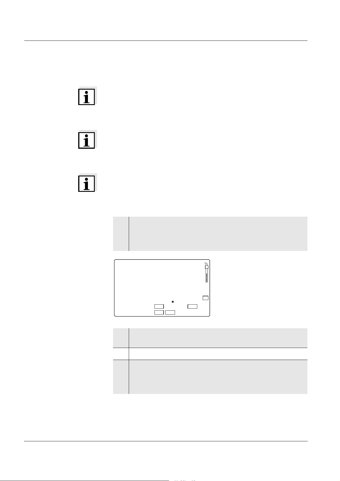
1
ON / OFF
M
AUTO READ
RUN / ENTER
CAL
2
O
7
92
m
g/
l
1 7 6
°
C
T
P
R
E
L
1
A
R
n
g
RCL
STO
Multi 1970i
3
4
5
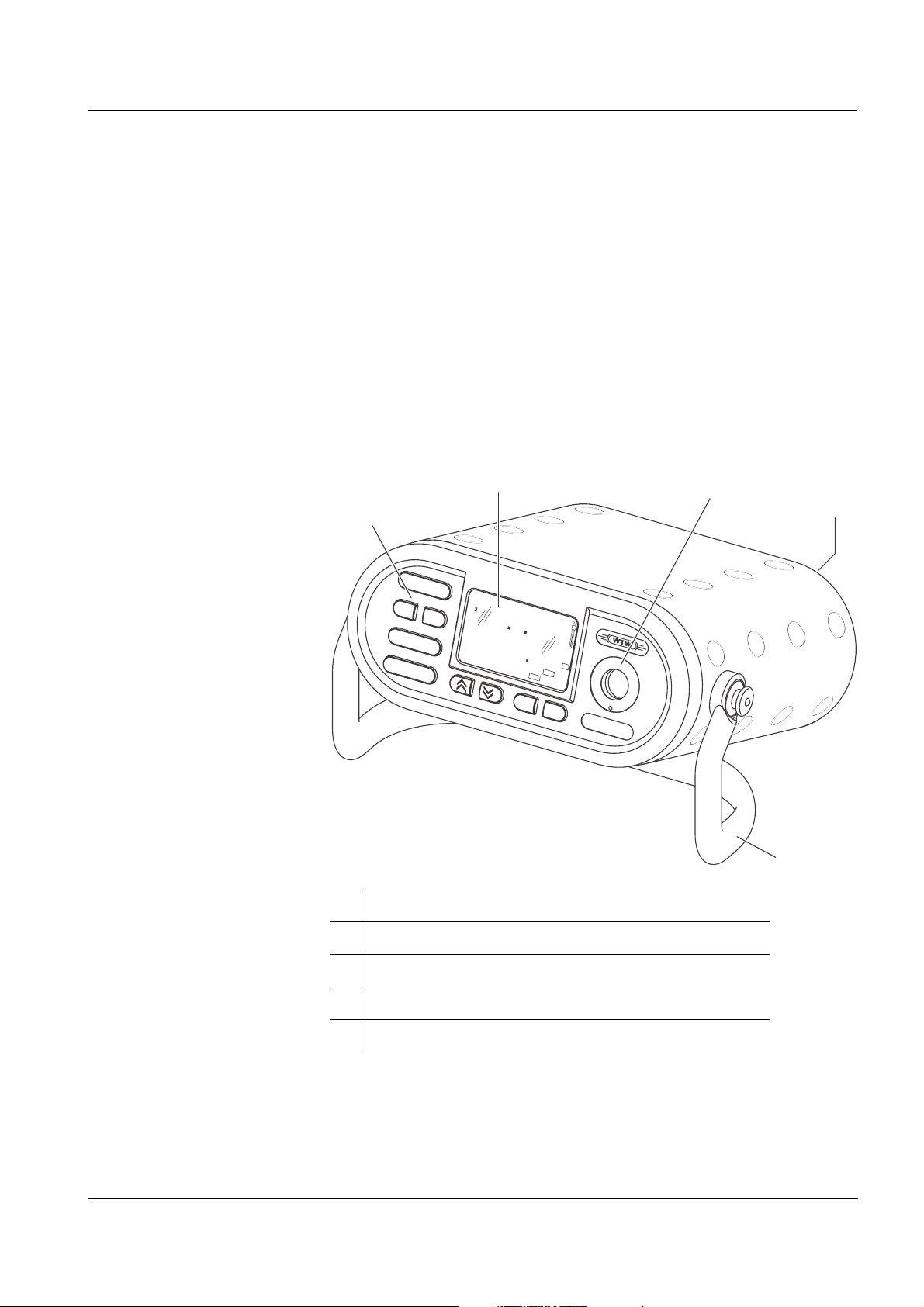
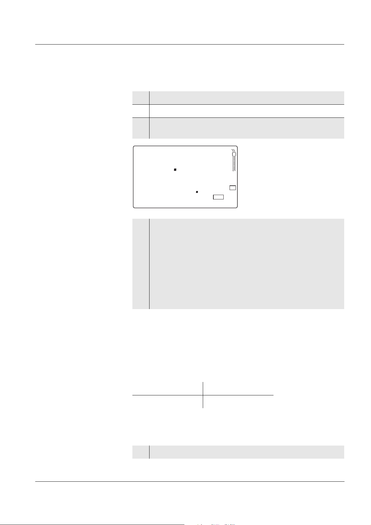
1 Keypad
2 Display
3 Integrated, exchangeable sensor quiver
4 Jack field
5 Carrying and positioning handle
3
Page 6
Overview Multi 1970i
Note
If you need further information or application notes, you can obtain the
following material from WTW:
z Application reports
z Primers
z Safety datasheets.
You will find information on available literature in the WTW catalog or
via the Internet.
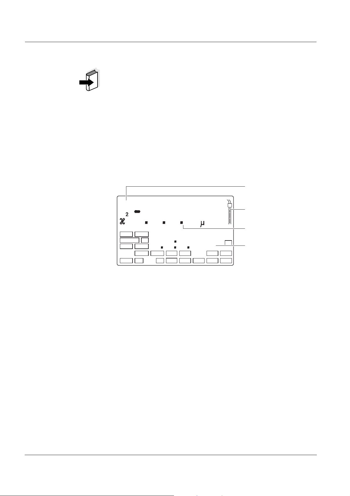
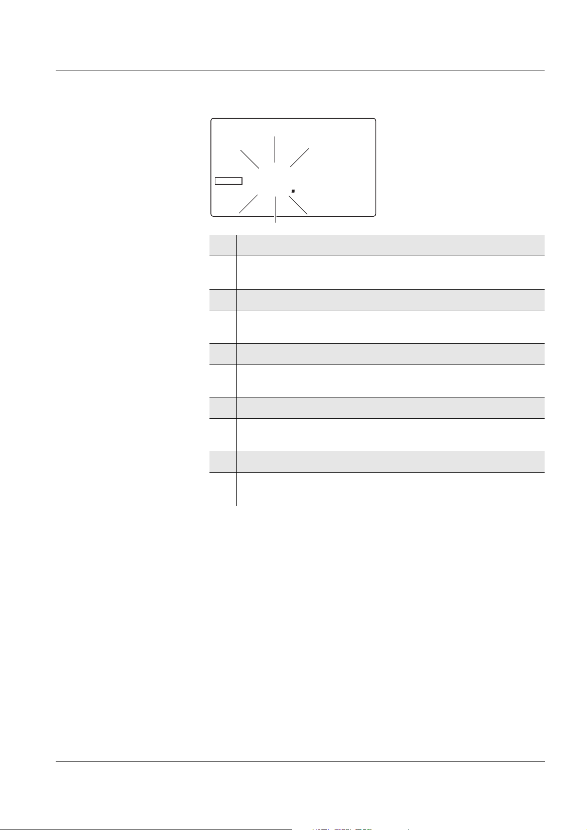
1.2 Display
Status display indicator
pH
S
O
Sal
1
Time
Day.Month
Year
LoBat nLF
8
88
Baud
No.
Ident
8 8 8 8
Tref25 Tref20
Lin
Auto
Oxi
Cal
Store
TEC
ARng
%
m
1/
°
S/
cm
%
C
REL1
pHmV/
mg/l
cm
K
/
REL2
AR
Sal
TP
RCL
Sensor symbol
Measured value
display
Function and
temperature display
4
Page 7
Multi 1970i Overview
RCL
STO
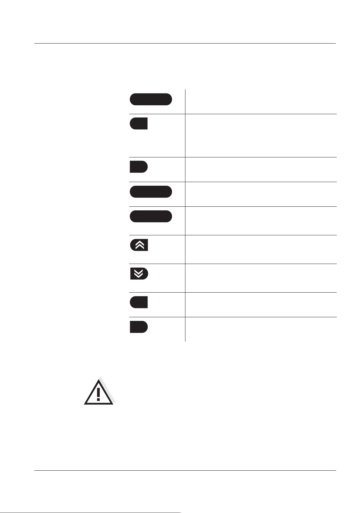
1.3 Keypad
Key functions
ON / OFF
M
CAL
AUTO READ
RUN / ENTER
Calibrate the currently set measured variable
Switch measuring instrument on/off
<ON/OFF>
Select the measured variable <M>:
– pH value / ORP voltage
– D. O. concentration / D. O. saturation
– Conductivity / salinity
<CAL>
Activate/deactivate the AutoRead function
<AUTO READ>
Confirm entries, start AutoRead,
output measured values
<RUN/ENTER>
Select the measuring mode, increase values,
scroll
<▲ >
Select the measuring mode, decrease values,
scroll
<▼ >
RCL
STO
Display/transmit measured values
<RCL>
Save a measured value
<STO>
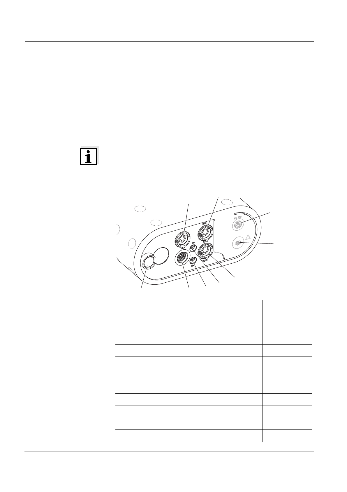
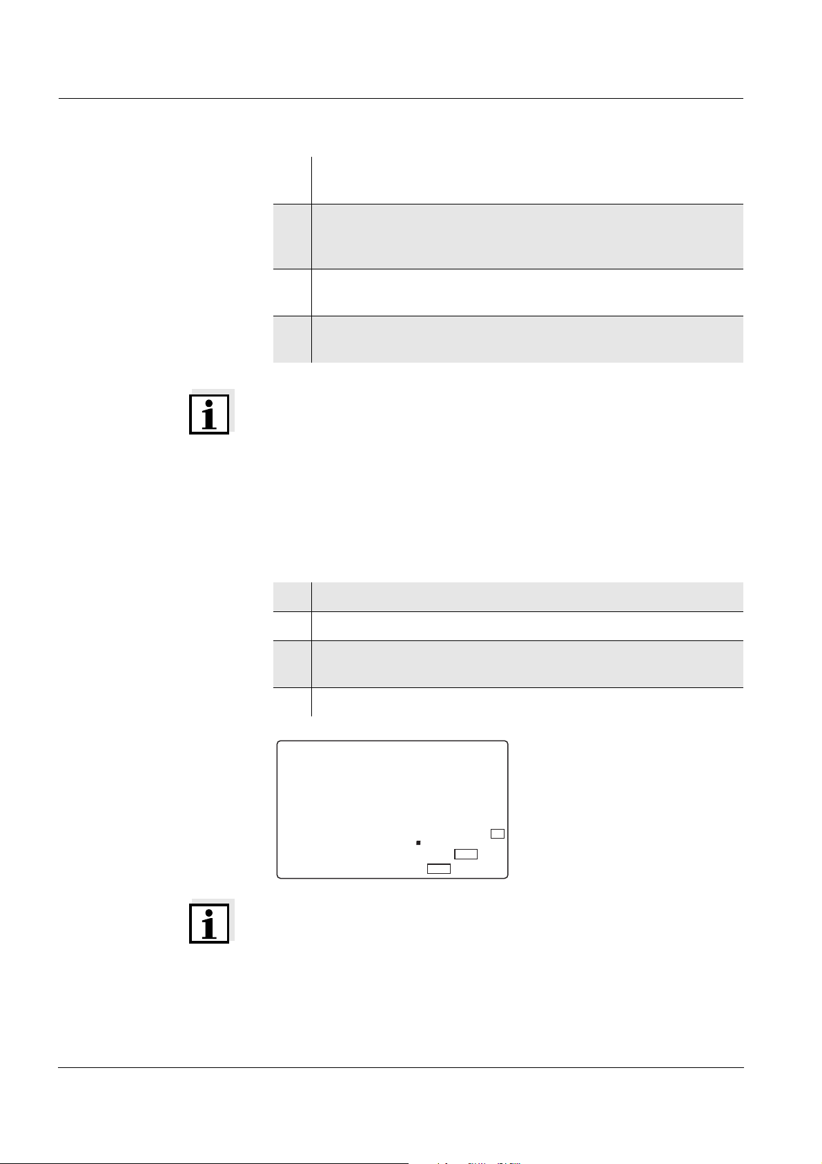
1.4 Jack field
Warning
Only connect sensors to the measuring instrument that cannot return
any voltages or currents that are not allowed (> SELV and > current circuit with current limiting).
Almost all sensors - in particular WTW sensors - fulfill these conditions.
5
Page 8
Overview Multi 1970i
Maximum number
of sensors to be con-
nected
Connectors:
The following sensors can be connected to the Multi 1970i (maximum
configuration):
z One pH depth armature or
one pH electrode (combination electrode
or pH electrode + reference electrode). Please make sure that only
one pH sensor is connected at the same time.
z One D. O. sensor
z One conductivity measuring cell
z Option: One external temperature sensor
Note
The pH depth armature is affected by other sensors if it is connected to
them galvanically. For this reason, the pH depth armature cannot be
operated in the same test sample together with another sensor on the
instrument.
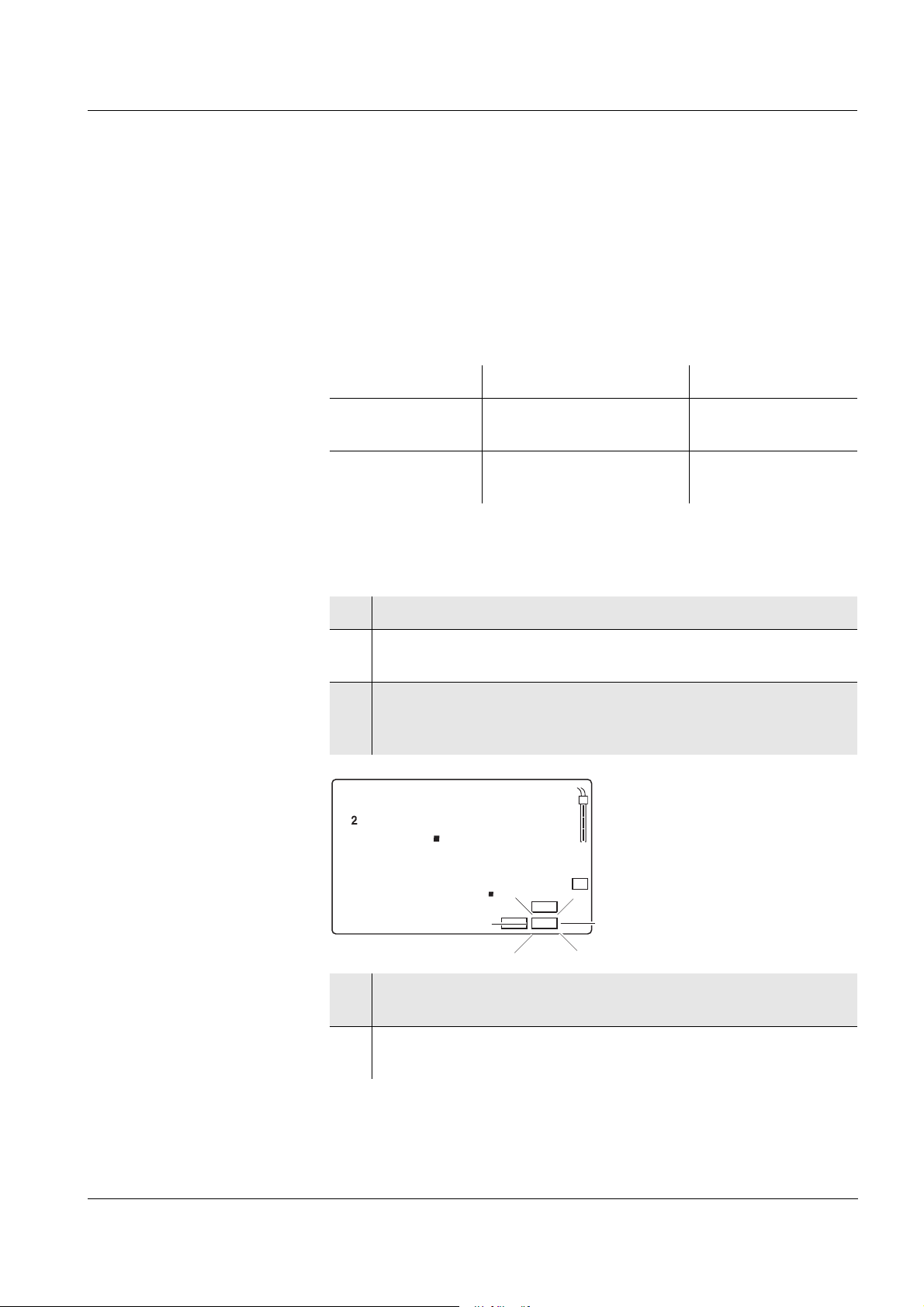
5
1
7
8
6
9
2
4
3
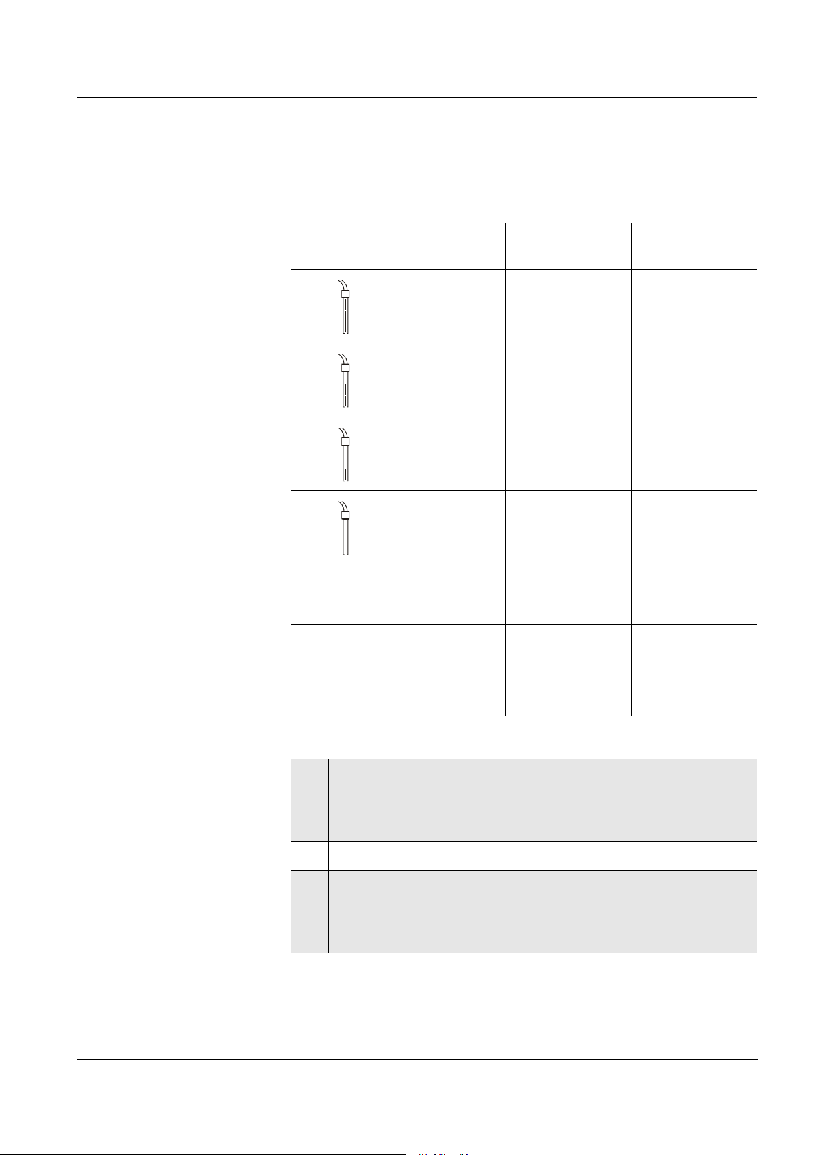
Sensor / Instrument Socket / Posi-
tion
pH depth armature 1
pH electrode or pH combination electrode 2
pH combination electrode with temperature sensor 2 and 4
Reference electrode 3
Temperature sensor, external 3 and 4
Oxygen sensor 5 or 6
Conductivity measuring cell 5 or 6
Printer or PC (serial interface, RS232) 7
Plug-in power supply unit 8
Watertight valve for internal pressure equalization 9
6
Page 9

Multi 1970i Overview
Note
The sensor sockets, 1 and 2 must not be assigned at the same time.
On the two sockets, 5 and 6, only different sensor types (Oxi and Cond)
may be connected at the same time.
7
Page 10

Overview Multi 1970i
8
Page 11
Multi 1970i Safety
2 Safety
This operating manual contains basic instructions that you must follow
during the commissioning, operation and maintenance of the measuring instrument. Consequently, all responsible personnel must read this
operating manual before working with the measuring system. The operating manual must always be available within the vicinity of the measuring system.
Target group The measuring instrument was developed for work in the field and in
the laboratory.
Thus, we assume that, as a result of their professional training and experience, the operators will know the necessary safety precautions to
take when handling chemicals.
Safety instructions The individual chapters of this operating manual use the following safe-
ty instruction to indicate various types of danger:
Warning
indicates instructions that must be followed precisely in order to avoid
the possibility of slight injuries or damage to the instrument or the environment.
Further notes
Note
indicates notes that draw your attention to special features.
Note
indicates cross-references to other documents, e.g. operating manuals.
2.1 Authorized use
The authorized use of the measuring instrument consists exclusively of
the:
z pH and ORP measurement
z measurement of the oxygen content and
z measurement of the conductivity, salinity and temperature
in the field and laboratory.
The technical specifications as given in chapter 7 T
must be observed. Only the operation and running of the measuring instrument according to the instructions given in this operating manual is
authorized. Any other use is considered to be unauthorized.
ECHNICAL DATA
9
Page 12

Safety Multi 1970i
2.2 General safety instructions
This instrument is built and inspected according to the relevant guidelines and norms for electronic measuring instruments (see chapter
7T
ECHNICAL DATA).
It left the factory in a safe and secure technical condition.
Function and operating
safety
Safe operation If safe operation is no longer possible, the instrument must be taken out
The smooth functioning and operational safety of the measuring instrument can only be guaranteed if the generally applicable safety measures and the specific safety instructions in this operating manual are
followed during operation.
The smooth functioning and operational safety of the measuring instrument can only be guaranteed under the environmental conditions that
are specified in chapter 7 T
ECHNICAL DATA.
If the instrument was transported from a cold environment to a warm
environment, the formation of condensate can lead to the faulty functioning of the instrument. In this event, wait until the temperature of the
instrument reaches room temperature before putting the instrument
back into operation.
of service and secured against inadvertent operation!
Safe operation is no longer possible if the measuring instrument:
z has been damaged in transport
z has been stored under adverse conditions for a lengthy period of
time
Obligations of the pur-
chaser
z is visibly damaged
z no longer operates as described in this manual.
If you are in any doubt, please contact the supplier of the instrument.
The purchaser of the measuring instrument must ensure that the following laws and guidelines are observed when using dangerous substances:
z EEC directives for protective labor legislation
z National protective labor legislation
z Safety regulations
z Safety datasheets of the chemical manufacturers.
10
Page 13
Multi 1970i Commissioning
3 Commissioning
3.1 Scope of delivery
z Multi 1970i portable multiparameter measuring instrument with inte-
grated rechargeable battery
z Carrying and positioning handle
z Carrying strap
z 2 sensor quivers (pH and Oxi-LF type)
z Plug-in power supply unit
z Operating manual
3.2 Power supply
Mains operation and
charging the battery
Charging time of the
battery
You can either operate the measuring instrument with the integrated rechargeable battery or with the plug-in power supply. The plug-in power
supply supplies the measuring instrument with low voltage (12 V DC).
At the same time, the rechargeable battery is charged.
approx. 16 hours. The battery is charged even when the instrument is
switched off. The LoBat display indicator appears when the battery is
nearly empty and has to be charged as soon as possible.
Warning
The line voltage at the operating site must lie within the input voltage
range of the original plug-in power supply (see chapter 7 T
TA).
ECHNICAL DA-
Warning
Use original plug-in power supplies only (see
chapter 7 T
ECHNICAL DATA).
11
Page 14
Commissioning Multi 1970i
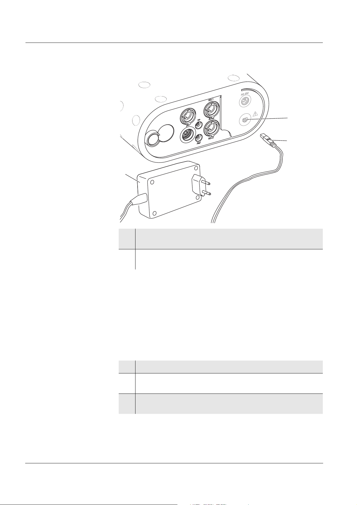
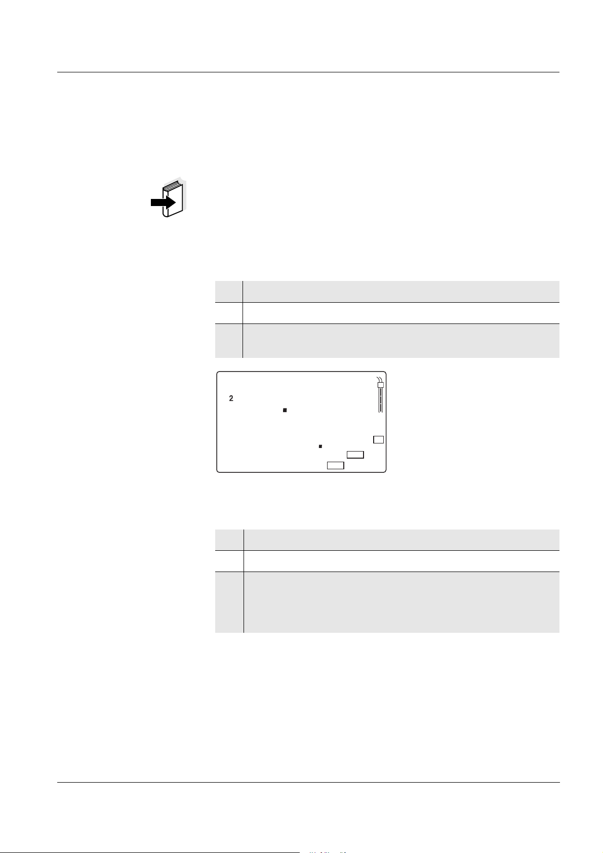
Connecting the plug-in
power supply unit
2
1
3
Setting the date and
time
1 Connect the plug (1) to the socket (2) of the measuring instru-
ment.
2 Connect the original WTW plug-in power supply (3) to an easily
accessible mains socket.
3.3 Initial commissioning
Perform the following activities:
z For mains operation and charging the battery: Connect the plug-in
power supply (see section 3.2 P
z Set the date and time.
1 Press the <M> key and hold it down.
2 Press the <ON/OFF> key.
The display test appears briefly on the display.
3 Press the <RUN/ENTER> key repeatedly until the date flashes
on the display (Day.Month display indicator).
OWER SUPPLY).
12
Page 15
Multi 1970i Commissioning
m
%
1/
°
mg/l
S/
cm
%
C
REL1
AR
pH/mV
cm
Sal
K
/
REL2
TP
RCL
pH
O
Sal
Time
Day.Month
Year
LoBat
S
I
Baud
No.
Ident
0 9 0 4
Tref25
Tref20
nLF
Lin
5t2
Auto
Store
Cal
Oxi
TEC
ARng
4 Set the date of the current day with <▲> <▼>.
5 Confirm with <RUN/ENTER>.
The date (month) flashes in the display.
6 Set the current month with <▲> <▼>.
7 Confirm with <RUN/ENTER>.
The year appears on the display.
8 Set the current year with <▲> <▼>.
9 Confirm with <RUN/ENTER>.
The hours flash on the display.
10 Set the current time with <▲> <▼>.
11 Confirm with <RUN/ENTER>.
The minutes flash on the display.
12 Set the current time with <▲> <▼>.
13 Confirm with <RUN/ENTER>.
The instrument switches to the measuring mode.
13
Page 16
Commissioning Multi 1970i
3.4 Sensor quiver
To store the sensors during field operation and to keep the sensor element moist, the quiver tip contains a sponge rubber insert that can be
moistened with deionized water.
Note
For further details on proper storage, refer to the operating manual of
the sensor.
Moistening the
quiver insert
1 Press the quiver out of the holder from the back side of the in-
strument and pull it out completely.
2 Pull off the quiver tip and moisten the sponge rubber with
deionized water.
Warning
Do not store pH electrodes in the quiver for more than 10 hours. To
store them for a longer period of time, use the watering cap filled with
potassium chloride (3 mol/l) of the electrode.
14
Page 17
Multi 1970i Operation
4 Operation
4.1 Operating structure
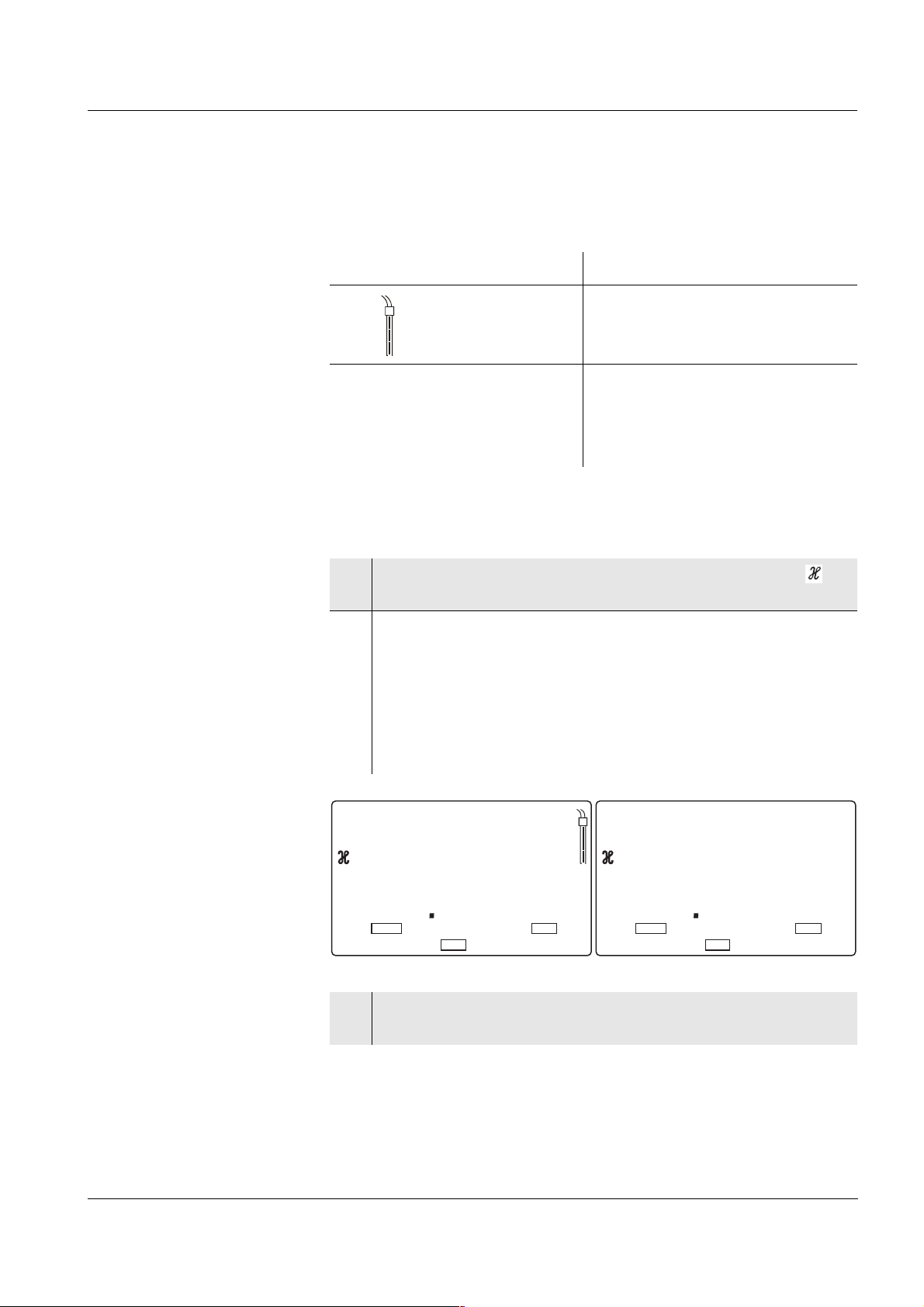
Active and inactive REL
socket
In addition to the pH/ORP sensor, the sensor on the REL1 or REL2
socket can be actuated (switched "active"). The other socket is not actuated ("inactive"). This switching over inside the instrument is made
with the aid of a relay. The active REL socket is shown on the display.
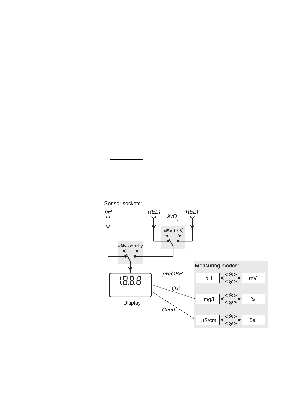
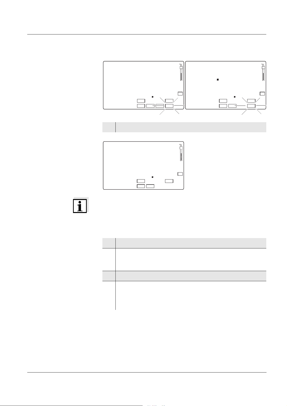
The measured variable on the display can be selected as follows using
the <M> key:
z Press <M> shortly
z Press <M> for a longer
period of time:
Several measuring modes are available within a measured variable.
Switch over between the measured variables with the <▲> or <▼> key.
The options are summarized in the following diagram:
: Switch between the pH/ORP sensor and
the sensor at the active REL socket
Change the active Rel socket
15
Page 18
Operation Multi 1970i
Note
When a sensor is connected to the active REL socket, the measuring
instrument recognizes the sensor or the measuring cell and automatically switches to the measuring mode that was last active. As soon as
the sensor is disconnected from the active REL socket, the instrument
switches to the pH (mV) measuring mode again.
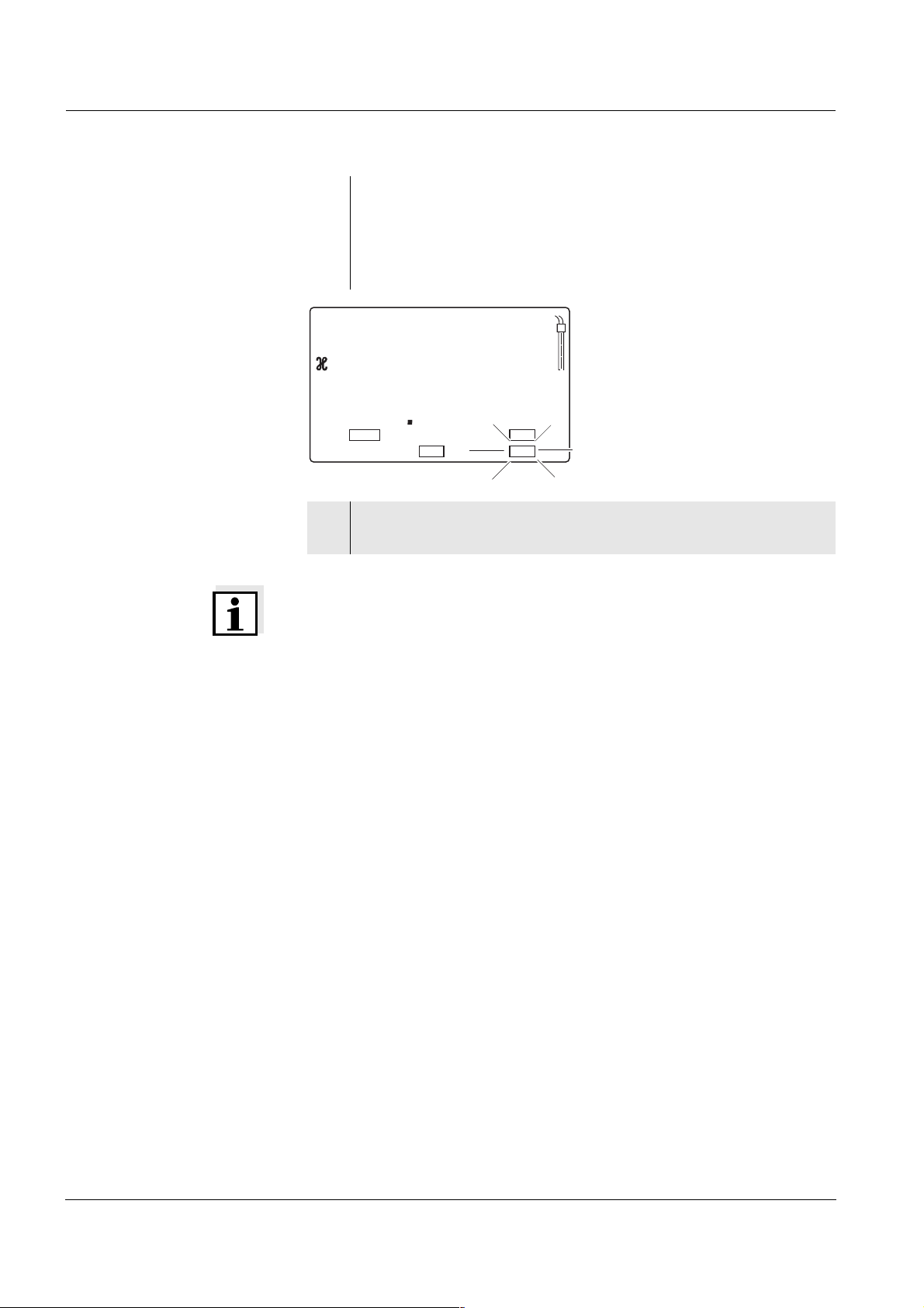
4.2 Switching on the measuring instrument
1 Press the <ON/OFF> key.
The display test appears briefly on the display.
After this, the measuring instrument automatically switches to
the measuring mode.
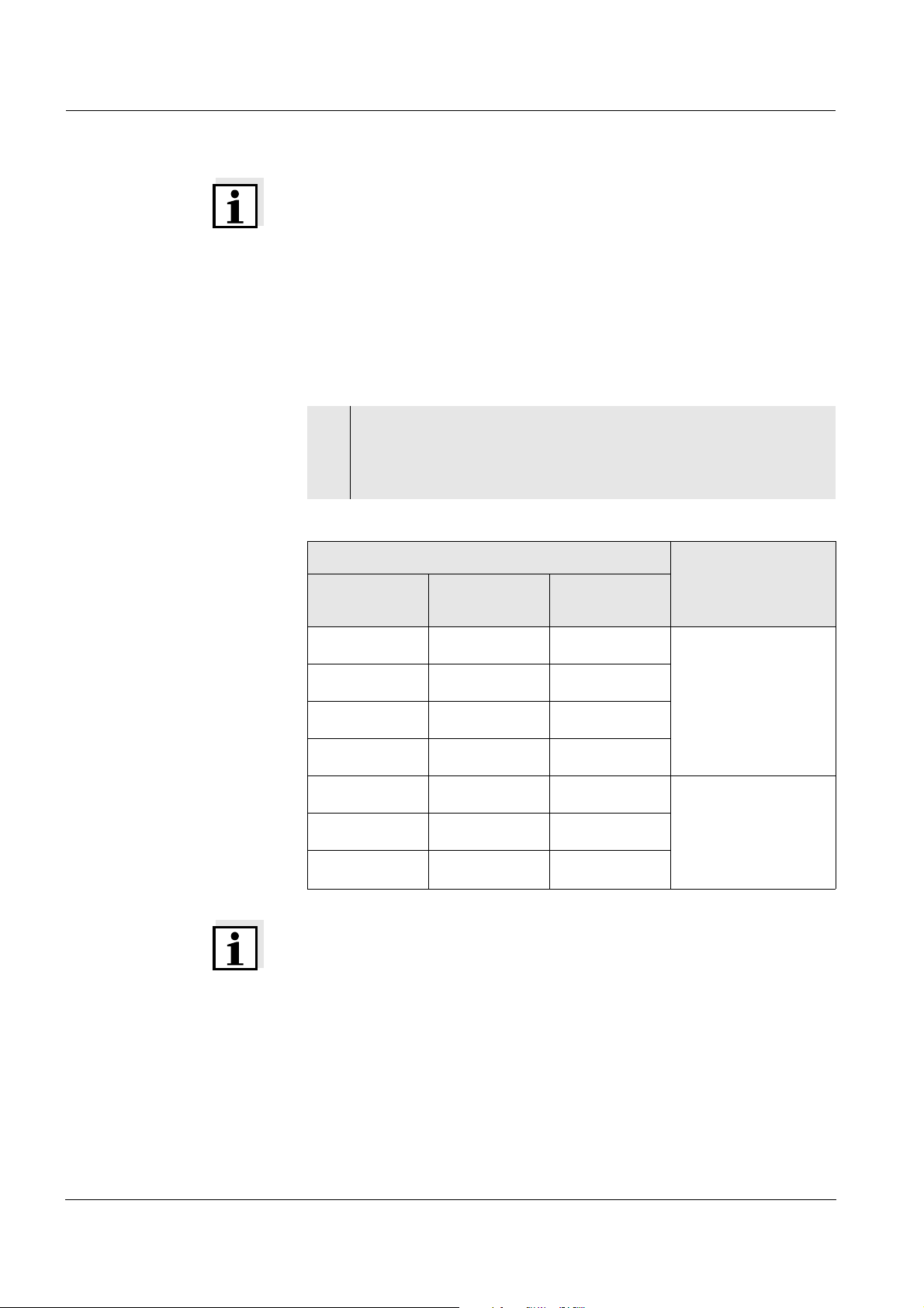
Measuring mode when
switching on
Sensors on the socket Measuring mode
pH REL
(active)
REL
(inactive)
:
pH or ORP measurement - depending on the last
selected setting
:
::
:
::
:::
Note
The measuring instrument has an energy saving feature to avoid unnecessary battery depletion. The energy saving feature switches the
measuring instrument off if no key has been pressed for an hour.
Last selected measuring mode.
Only the last active
REL socket is taken into account
16
The energy saving feature is not active
z if the power is supplied by the plug-in power supply,
z if the AutoStore function is active,
z if the communication cable and a PC with a running communication
program are connected,
z if the printer cable is connected (for external printers).
Page 19
Multi 1970i Operation
4.3 pH value / ORP voltage
4.3.1 General information
Preparatory activities Perform the following preparatory activities when you want to measure:
1 Connect the pH depth armature or the pH electrode to the mea-
suring instrument.
If necessary, press the <M> key repeatedly until the pH (pH
measurement) or U (measurement of the ORP voltage) display
appears.
2 Adjust the temperature of the buffer solutions or test solutions,
or measure the current temperature, if you measure without a
temperature sensor.
3 Calibrate or check the measuring instrument with the elec-
trode.
4 Using <▲ > <▼>, toggle between the pH or mV measuring
modes.
Note
Incorrect calibration of pH electrodes leads to incorrect measured values. Calibrate regularly before measuring. You can only connect electrodes of the NTC30 type or without temperature sensor.
Warning
When connecting an earthed PC/printer, measurements cannot be performed in earthed media as incorrect values would result. The RS232
interface is not galvanically isolated.
17
Page 20

Operation Multi 1970i
Temperature measure-
ment in pH measure-
ments
You can perform pH measurements with or without a temperature sensor as well as with the temperature sensor of an oxygen sensor or a
conductivity measuring cell. The measuring instrument recognizes
which sensors are connected and switches automatically to the correct
mode for the temperature measurement.
The following cases are distinguishable.
Temperature sensor Display Mode
pH Cond or
Oxi
yes - TP Automatic with
pH temperature sensor
yes yes TP
- - Manual
-yesTP
flashes
The temperature value of the
second sensor (Cond or Oxi)
in the same sample is taken
over for the pH measurement*
* If you do not wish that, you can:
– either disconnect the 2nd sensor and use the manual temperature
input or
– use an electrode with a temperature sensor.
If a temperature sensor is connected, it is indicated on the display by
TP.
Note
When calibrating without a temperature sensor (no TP display indicator
displayed), enter the current temperature of the respective buffer solution manually using the <▲> <▼> keys while keeping the <RUN/EN-
TER> key depressed.
18
Page 21
Multi 1970i Operation
4.3.2 Measuring the pH value
1 Perform the preparatory activities according to section 4.3.1.
2 Immerse the pH electrode in the test sample.
3 Press the <▲> <▼> keys repeatedly until pH appears on the
status display. The pH value appears on the display.
AutoRead AR
(Drift control) and hold
function
m
%
1/
°
mg/l
S/
cm
cm
%
C
REL1
AR
pH/mV
Sal
TP
K
/
REL2
RCL
pH
S
O
Sal
Time
Day.Month
Year
LoBat nLF
4 When measuring without a connected temperature sensor:
The AutoRead function (drift control) checks the stability of the measurement signal. The stability has a considerable impact on the reproducibility of the measured values. With the aid of the hold function the
measured value display is frozen.
6
1
Baud
No.
Ident
Tref25 Tref20
Options:
z Determine the current temperature using a thermometer
z TP display indicator not displayed, socket for the second
99
8
2 4 8
Auto
Store
Lin
Oxi
Cal
TEC
ARng
and, while keeping the <RUN/ENTER> key depressed, enter this temperature value with <▲> <▼>.
sensor is free:
Connect the second sensor (Oxi or Cond) and immerse it in
the same sample. TP flashes, the temperature is automatically measured using the second sensor.
With identical measurement conditions, the following criterion is valid
for the AutoRead function:
Reproducibility Response time
Better than 0.02 > 30 seconds
For D. O. measurements, use the AutoRead function and hold function
like this:
1 Call up the pH measuring mode with <▲> <▼>.
19
Page 22
Operation Multi 1970i
2 Activate the AutoRead function with <AUTO READ>.
The current measured value is frozen (hold function).
3 Start AutoRead with <RUN/ENTER>.
AR flashes until a stable measured value is reached.
This measured value is transmitted to the interface.
4 If necessary, start the next AutoRead measurement with
<RUN/ENTER>.
5 To terminate the AutoRead function: Press the
<AUTO READ> key.
Note
The current AutoRead measurement can be terminated at any time
(accepting the current value) by pressing <RUN/ENTER>.
4.3.3 Measuring the ORP voltage
In conjunction with an ORP electrode, e.g. SenTix ORP, the measuring
instrument can measure the ORP voltage (U) of a solution.
1 Perform the preparatory activities according to section 4.3.1.
2 Submerse the ORP electrode in the sample.
3 Press the <▲> <▼> key until the U status display appears. The
ORP voltage (mV) of the test sample appears on the display.
4 Wait for a stable measured value.
pH/
Store
TEC
ARng
mV
%
m
1/
°
mg/l
S/
cm
%
C
REL1
AR
cm
K
/
REL2
Sal
TP
RCL
pH
S
O
Sal
Time
Day.Month
Year
LoBat nLF
Note
ORP electrodes are not calibrated. However, you can check ORP electrodes using a test solution.
1
Baud
Ident
Tref25
No.
6
8
Tref20
Lin
Oxi
23
2 4 8
Auto
Cal
20
Page 23

Multi 1970i Operation
4.3.4 pH calibration
Why calibrate? pH electrodes age. This changes the asymmetry (zero point) and slope
of the pH electrode. As a result, an inexact measured value is displayed. Calibration determines the current values of the asymmetry
and slope of the electrode and stores them in the measuring instrument. Thus, you should calibrate at regular intervals.
When to calibrate? z After connecting another electrode
z When the sensor symbol flashes, i.e. after the calibration interval
has expired
Calibration points Calibration can be made with one or two buffer solutions (single-point
or two-point calibration). The measuring instrument determines the following values and calculates the calibration lines as follows:
Determined values Values of the calibration lines
1-point ASY z Asymmetry = ASY
z Slope = Nernst slope (59.16 mV/
pH at 25 °C)
2-point ASY
SLO
z Asymmetry = ASY
z Slope = SLO
AutoCal TEC is specially matched to the WTW technical buffer solutions as a fully au-
tomatic two-point calibration. The buffer solutions are automatically
recognized by the measuring instrument. Depending on the instrument
setting (see section 4.9 C
ONFIGURATION), the instrument displays the
relevant buffer nominal value or the current electrode voltage in mV.
The calibration can be terminated after the first buffer solution. This corresponds to a single-point calibration. To do this, the instrument uses
the Nernst slope (-59.2 mV/pH at 25 °C) and determines the asymmetry of the electrode.
AutoRead The calibration procedure automatically activates the AutoRead func-
tion.
The current AutoRead measurement can be terminated at any time
(accepting the current value) by pressing <RUN/ENTER>.
Displaying the calibra-
tion data
Printing the
calibration protocol
You can view the data of the last calibration on the display. The proceeding is described on page 50.
The calibration protocol contains the calibration data of the current calibration. You can transmit the calibration protocol to a printer via the serial interface (see O
INTERFACE, page 53).
UTPUTTING THE CALIBRATION PROTOCOL ON THE
21
Page 24

Operation Multi 1970i
Note
You can automatically print a calibration protocol after the calibration.
To do so, connect a printer to the interface according to section 4.8.2
before calibrating. After a valid calibration, the record is printed.
Sample printout:
CALIBRATION PROTOCOL
02.03.02 14:19
Device No.: 12345678
Calibration pH
Cal time: 01.03.01 / 15:20
Cal interval: 7d
AutoCal TEC Tauto
Buffer 1 2.00
Buffer 2 4.01
Buffer 3 7.00 *
Buffer 4 10.01
C1 184.1 mV 25.0°C
C2 3.0 mV 25.0°C
S1 -59.4 mV/pH
ASY1 - 4 mV
Probe: +++
22
Page 25
Multi 1970i Operation
Calibration evaluation After calibrating, the measuring instrument automatically evaluates the
calibration. The asymmetry and slope are evaluated separately. The
worst evaluation appears on the display.
Display Asymmetry
[mV]
-15 ... +15 -60.5 ... -58
-20 ... +20 -58 ... -57
-25 ... +25 -61 ... -60.5
-30 ... +30 -62 ... -61
Clean the electrode according
to the electrode operating
manual
Slope
[mV/pH]
or
-57 ... -56
or
-56 ... -50
Preparatory activities
E3
Perform error elimination according to chapter 6 W
DO IF...
HAT TO
< -30 or
> 30
< -62 or
> -50
1 Connect the pH electrode to the measuring instrument.
If necessary, press the <M> key repeatedly until the status display pH (pH measurement) or U (measurement of the ORP
voltage) appears.
2 Keep the buffer solutions ready.
3 Adjust the temperature of the solution and measure the current
temperature if the measurement is made without the use of a
temperature sensor (the TP display indicator is missing from
the display).
23
Page 26
Operation Multi 1970i
AutoCal TEC For this procedure, use any two WTW technical buffer solutions (pH
values at 25 °C: 2.00 / 4.01 / 7.00 / 10.01).
Note
The calibration for pH 10.01 is optimized for the WTW technical buffer
solution TEP 10 Trace or TPL 10 Trace. Other buffer solutions can lead
to an erroneous calibration. The correct buffer solutions are given in the
WTW catalog or in the Internet.
Note
The buffer solutions are automatically recognized by the measuring instrument. Depending on the instrument setting (see
section 4.9 C
er nominal value or the current electrode voltage in mV.
Note
Skip the steps 2 and 7 if you use a pH electrode with temperature sensor or the temperature sensor of a conductivity measuring cell or a D.
O. sensor.
ONFIGURATION), the instrument displays the relevant buff-
Starting the calibration
1 Press the <CAL> key. The Ct1 display and the function display
AutoCal TEC appears. The sensor symbol displays the evalu-
ation of the last calibration (or no sensor symbol in the delivery
state or after the measurement parameters have been reset).
m
%
1/
°
mg/l
S/
cm
%
C
REL1
AR
pH/mV
cm
K
/
Sal
TP
REL2
RCL
pH
S
O
Sal
Time
Day.Month
Year
LoBat nLF
2 If required, enter the temperature of the first buffer solution with
3 Immerse the pH electrode in the first buffer solution.
4 Press the <RUN/ENTER> key.
C
Lin
8
Oxi
T1
2 4 8
Store
Auto
TEC
ARng
Cal
1
Baud
No.
Ident
Tref25 Tref20
<▲> <▼> while keeping the <RUN/ENTER> key depressed.
The AR display indicator flashes.
The electrode voltage (mV) or the buffer nominal value appears on the display. Example:
24
Page 27
Multi 1970i Operation
mVS/
m
%
1/
°
mg/l
S/
cm
%
C
REL1
AR
pH
cm
K
/
REL2
Sal
TP
RCL
/
pH
3
TEC
ARng
mV
%
m
1/
°
mg/l
S/
cm
%
C
REL1
AR
cm
/
pH
S
O
Sal
Time
Day.Month
Year
LoBat nLF
5 When the measured value is stable, Ct2 appears.
1
Baud
No.
Ident
Tref25 Tref20
Lin
69
8
2 4 8
Auto
Oxi
Cal
K
Sal
TP
REL2
RCL
pH
O
Sal
1
Time
Day.Month
Year
LoBat nLF
700
Baud
No.
Ident
8
Lin
Oxi
2 4 8
Auto
Cal
Tref25 Tref20
TEC
ARng
m
%
1/
°
mg/l
S/
cm
%
C
REL1
AR
pH/mV
cm
Sal
K
/
REL2
TP
RCL
pH
S
O
Sal
Time
Day.Month
Year
LoBat nLF
Note
At this point, the AutoCal TEC calibration can be terminated with <M>.
This corresponds to a single-point calibration. To do this, the instru-
ment uses the Nernst slope (-59.2 mV/pH at 25 °C) and determines the
asymmetry of the electrode.
6 Thoroughly rinse the electrode with distilled water.
7 If required, enter the temperature of the second buffer solution
8 Immerse the pH electrode into the second buffer solution.
9 Press the <RUN/ENTER> key.
C
Lin
8
Oxi
T2
2 4 8
Store
Auto
TEC
ARng
Cal
1
Baud
No.
Ident
Tref25 Tref20
with <▲> <▼> while keeping the <RUN/ENTER> key depressed.
The AR display indicator flashes.
The electrode voltage (mV) or the buffer nominal value appears on the display. Example:
25
Page 28

Operation Multi 1970i
mVS/
m
%
1/
°
mg/l
S/
cm
%
C
REL1
AR
pH
cm
K
/
REL2
Sal
TP
RCL
pH
O
Sal
1
Time
Day.Month
Year
LoBat nLF
S
Baud
No.
Ident
Tref25 Tref20
Lin
8
2 4 8
Auto
Oxi
Cal
TEC
ARng
mV
%
m
1/
°
/
mg/l
S/
cm
%
C
REL1
AR
pH
cm
K
/
REL2
Sal
TP
RCL
pH
O
Sal
1
Time
Day.Month
Year
LoBat nLF
401184
Baud
No.
Ident
8
Tref25 Tref20
Lin
Oxi
2 4 8
Auto
TEC
ARng
Cal
10 When the measured value is stable, AR disappears. The value
of the slope (mV/pH) appears on the display. The sensor symbol shows the evaluation of the current calibration.
%
m
1/
°
S/
C
pH/mV
mg/l
cm
cm
%
/
REL1
AR
K
Sal
TP
REL2
RCL
pH
S
O
Sal
1
Time
Day.Month
Year
LoBat nLF
594
Baud
No.
Ident
Tref25 Tref20
Lin
8
Oxi
2 4 8
Auto
Cal
Store
TEC
ARng
11 Press the <RUN/ENTER> key. The value of the asymmetry
(mV) appears on the display.
pH/
2
Store
TEC
ARng
mV
%
m
1/
°
mg/l
S/
cm
%
C
REL1
AR
cm
K
/
REL2
Sal
TP
RCL
pH
S
O
Sal
1
Time
Day.Month
Year
LoBat nLF
59
Baud
No.
Ident
8
Tref25 Tref20
Lin
2 4 8
Auto
Oxi
Cal
12 Switch to the measuring mode with <M>.
26
Page 29
Multi 1970i Operation
4.4 Dissolved oxygen
4.4.1 General information
Note
D. O. measurements with the Multi 1970i can only be carried out using
a CellOx 325 or StirrOx G D. O. sensor. The stirrer of the StirrOx G
D. O. sensor has to be supplied with voltage separately using the
NT/pH Mix 540 power supply.
You can measure the following variables:
z D. O. concentration
z Oxygen saturation
The measuring instrument is supplied with the following functions:
z AutoRange (automatic switchover of the measurement range). If a
measuring range is exceeded, AutoRange causes the measuring instrument to change automatically to the next higher measuring
range and back again. Therefore, the instrument always measures
in the measuring range with the highest possible resolution.
z The AutoRead function (drift control) for checking the stability of the
measurement signal. This ensures the reproducibility of the measuring signal. For details of how to switch the AutoRead function on/off,
see page 31.
Warning
When connecting an earthed PC/printer, measurements cannot be performed in earthed media as incorrect values would result.
The RS232 interface is not galvanically isolated.
Preparatory activities Perform the following preparatory activities when you want to measure:
1 Connect the D. O. sensor to the measuring instrument. If the D.
O. sensor is connected to the active REL socket, press the
<M> repeatedly if necessary until the O
status display indica-
2
tor appears. If the D. O. sensor is connected to the inactive
REL socket, press the <M> key for 2 s, until the O
status dis-
2
play indicator appears.
2 Calibrate or check the measuring instrument with the sensor.
How to calibrate is described in section 4.4.5 from page 21.
3 Use <▲> <▼> to toggle between the measuring modes, D. O.
concentration (mg/L) and D. O. saturation (%).
27
Page 30

Operation Multi 1970i
Note
Incorrect calibration of D. O. probes will result in incorrect measured
values.
Calibrate at regular intervals.
Temperature sensor The D. O. sensor has an integrated temperature sensor that always
measures the current temperature of the test sample.
28
Page 31
Multi 1970i Operation
4.4.2 Measuring the D. O. concentration
When measuring the concentration of test samples with a salt content
of more than 1 g/l, a salinity correction is required.
Note
How to enter the current salt content is described in
section 4.4.6 E
Switching the salt content correction on or off, see below.
To measure the D. O. concentration with and without salt content correction, proceed as follows:
1 Perform the preparatory activities according to section 4.4.1.
2 Immerse the D. O. sensor in the test sample.
3 Press the <▲> <▼> key repeatedly until the D. O. concentra-
tion in mg/l appears on the display.
NTERING THE SALT CONTENT (SALINITY) on page 35.
Switching on/off the salt
content correction
m
%
1/
°
mg/l
S/
cm
%
C
REL1
AR
pH/mV
cm
Sal
K
/
REL2
TP
RCL
pH
S
O
Sal
Time
Day.Month
Year
LoBat nLF
Proceed as follows to switch on the salt content correction:
1 Perform the preparatory activities according to section 4.4.1.
2 Immerse the D. O. sensor in the test sample.
3 While pressing the <RUN/ENTER> key, switch on the salt con-
7
Lin
8
Oxi
92
1 7 6
Auto
Store
Cal
TEC
ARng
1
Baud
No.
Ident
Tref25 Tref20
tent correction with <▲> . The SAL display indicator appears
on the display. The specified salt content is taken into consideration during the measurement.
29
Page 32

Operation Multi 1970i
%
m
1/
°
S/
C
pH/mV
mg/l
cm
cm
%
/
REL1
AR
K
Sal
TP
REL2
RCL
pH
S
O
Sal
Time
Day.Month
Year
LoBat nLF
4 While pressing the <RUN/ENTER> key, switch off the salt con-
4.4.3 Measuring the D. O. saturation
You can measure the D. O. saturation as follows:
1 Perform the preparatory activities according to section 4.4.1.
2 Immerse the D. O. sensor in the test sample.
5
Lin
8
Oxi
42
1 7 6
Auto
Store
Cal
TEC
ARng
1
Baud
No.
Ident
Tref25 Tref20
tent correction with <▼>. The SAL display indicator is no longer
displayed.
3 Press the <▲> <▼> key repeatedly until the D. O. saturation in
% appears on the display.
/mV
%
m
1/
°
S/
C
pH
mg/l
cm
cm
%
/
REL1
AR
K
Sal
TP
REL2
RCL
pH
S
O
Sal
1
Time
Day.Month
Year
LoBat nLF
8
Baud
No.
Ident
8
Tref25 Tref20
Lin
92
1 7 6
Auto
Oxi
Cal
Store
TEC
ARng
30
Page 33
Multi 1970i Operation
4.4.4 AutoRead AR (Drift control) and hold function
The AutoRead function (drift control) checks the stability of the measurement signal. The stability has a considerable impact on the reproducibility of the measured values. With the aid of the hold function the
measured value display is frozen.
Criteria With identical measurement conditions, the following criteria are valid
for the AutoRead function:
Measuring mode Reproducibility Response time
D. O. concentration
Oxygen saturation
index
For D. O. measurements, use the AutoRead function and hold function
like this:
1 Call up the measuring mode with <M> and/or <▲> <▼> .
2 Activate the AutoRead function with <AUTO READ>. The cur-
rent measured value is frozen (hold function).
3 Start AutoRead with <RUN/ENTER>.
AR flashes until a stable measured value is reached. This measured value is transmitted to the interface.
pH
S
O
Sal
Time
Day.Month
Year
LoBat nLF
1
Baud
No.
Ident
Tref25 Tref20
Lin
7
8
1 7 6
Oxi
08
Auto
better than 0.05 mg/l > 10 seconds
better than 0.6 % > 10 seconds
pH/mV
mg/l
%
m
S/
cm
1/
cm
Sal
TP
K
%
°
/
ARng
C
REL1
AR
REL2
RCL
Store
Cal
TEC
4 If necessary, start the next AutoRead measurement with
<RUN/ENTER>.
5 To terminate the AutoRead function: Press the
<AUTO READ> key.
31
Page 34

Operation Multi 1970i
4.4.5 D. O. calibration
Why calibrate? D. O. probes age. This changes the slope of the D. O. sensor. Calibra-
tion determines the current slope of the sensor and stores this value in
the instrument.
When to calibrate? z After connecting another D. O. sensor
z When the sensor symbol flashes (after the calibration interval has
expired).
Calibration procedure The calibration is performed in water vapor-saturated air. Use the
®
OxiCal
-SL air calibration vessel (accessory) for the calibration.
AutoRead The calibration procedure automatically activates the AutoRead func-
tion. The AR display indicator flashes. The calibration process is finished when AR stops flashing.
Displaying the calibra-
tion data
Printing the
calibration protocol
You can view the data of the last calibration on the display. The proceeding is described on page 50.
The calibration protocol contains the calibration data of the current calibration. You can transmit the calibration protocol to a printer via the serial interface (see page 53).
Note
You can automatically print a calibration protocol after the calibration.
To do so, connect a printer to the interface according to section 4.8.2
before calibrating. After a valid calibration, the record is printed.
Sample printout:
CALIBRATION PROTOCOL
02.03.02 14:19
Device No.: 12345678
CALIBRATION 02
Cal time: 02.03.01 / 14:19
Cal interval: 14d
OxiCal Tauto AR
Relative Slope: 0,88
Probe: +++
32
Page 35

Multi 1970i Operation
Sensor evaluation After the calibration, the measuring instrument evaluates the current
status of the sensor against the relative slope. The evaluation appears
on the display. The relative slope has no effect on the measuring accuracy. Low values indicate that the electrolyte will soon be depleted and
the sensor will have to be regenerated.
Display Relative slope
S = 0.8 ... 1.25
S = 0.7 ... 0.8
S = 0.6 ... 0.7
E3
S < 0.6 or S > 1.25
Perform error elimination according to chapter 6 W
HAT TO DO IF...
Starting the calibration Proceed as follows to calibrate the instrument:
1 Perform the preparatory activities according to section 4.4.1.
®
2 Keep the OxiCal
-SL air calibration vessel ready.
Note
The sponge in the air calibration vessel must be moist (not wet). Observe the instructions in the OxiCal
®
-SL operating manual.
3 Put the D. O. sensor into the air calibration vessel.
4 Press the <CAL> key repeatedly until the calibration mode ap-
pears. The sensor symbol displays the evaluation of the last
calibration (or no sensor symbol in the delivery state or after the
measuring parameters have been reset).
33
Page 36

Operation Multi 1970i
m
m
%
1/
°
%
1/
°
mg/l
S/
cm
%
C
REL1
AR
mg/l
S/
cm
%
C
REL1
AR
pH/mV
cm
K
/
REL2
pH/mV
cm
K
/
REL2
Sal
TP
RCL
Sal
TP
RCL
pH
S
O
Sal
Time Baud
Day.Month
Year
LoBat
5 Press the <RUN/ENTER> key. AutoRead is active, AR flashes.
pH
1
No.
Ident
Tref25 Tref20
Lin
nLF
S
C
8
1 7 6
Oxi
AL
Auto
Store
ARng
TEC
Cal
O
Sal
Time Baud
Day.Month
Year
LoBat
6 As soon as a stable value is achieved the AR display stops
0
Lin
8
Oxi
88
1 7 6
Auto
Store
ARng
TEC
Cal
1
No.
Ident
Tref25 Tref20
nLF
flashing. The calibration is finished then. The value of the relative slope appears on the display. The sensor symbol shows
the sensor evaluation (see page 33).
%
m
1/
°
S/
C
pH/mV
mg/l
cm
cm
%
/
REL1
AR
K
Sal
TP
REL2
RCL
pH
S
O
Sal
Time Baud
Day.Month
Year
LoBat
7 Switch to the measuring mode with <M>.
Note
In chapter 6 W
to take for error elimination.
1
No.
Ident
Tref25 Tref20
Lin
nLF
0
88
8
1 7 6
Auto
Store
ARng
Oxi
TEC
Cal
HAT TO DO IF... from page 67, you will find the measures
34
Page 37

Multi 1970i Operation
4.4.6 Entering the salt content (salinity)
A salt content correction is required in the oxygen concentration measurement of samples with a salt content of more than 1 g/l. To do this,
you have to enter the salinity equivalent (the measured salinity) of the
test sample (range 0.0 - 70.0) and to switch on the salinity correction.
Note
With the Multi 1970i, you can measure the salinity. How to proceed is
described in section 4.5.3 M
EASURING THE SALINITY on page 38.
Entering the
salt content
1 Determine the salinity of the test sample (any method, see also
section 4.5.3 M
2 Press the <CAL> key repeatedly until Sal appears on the dis-
play.
pH
S
O
Sal
Time Baud
Day.Month
Year
LoBat
3 Enter the salt content with <▲> <▼>.
4 Switch to the measuring mode with <M>.
Note
How to switch on the salt content correction is described on page 29.
1
No.
Ident
Tref25 Tref20
Lin
nLF
5
8
6 9 6
Oxi
50
Auto
Cal
EASURING THE SALINITY on page 38).
pH/mV
mg/l
%
m
S/
cm
1/
cm
Sal
TP
K
%
°
/
ARng
C
REL1
AR
REL2
RCL
Store
TEC
35
Page 38

Operation Multi 1970i
4.5 Conductivity
4.5.1 General information
Note
Conductivity measurements with the Multi 1970i can only be carried out
using the TetraCon 325 measuring cell.
Warning
When connecting an earthed PC/printer, measurements cannot be performed in earthed media as incorrect values would result.
The RS232 interface is not galvanically isolated.
The measuring instrument is supplied with the following functions:
z AutoRange (automatic switchover of the measurement range). If a
measuring range is exceeded, AutoRange causes the measuring instrument to change automatically to the next higher measuring
range and back again. Therefore, the instrument always measures
in the measuring range with the highest possible resolution.
z The AutoRead function (drift control) for checking the stability of the
measurement signal. This ensures the reproducibility of the measuring signal. For details of how to switch the AutoRead function on/off,
see page 39.
Preparatory activities Perform the following preparatory activities when you want to measure:
1 Connect a conductivity measuring cell to the measuring instru-
ment. If the conductivity measuring cell is connected to the active REL socket, press the <M> key repeatedly (if necessary)
until the status display appears. If the conductivity measuring cell is connected to the inactive REL socket, press the <M>
key for 2 s until the status display appears.
2 Check the selected cell constant or calibrate the measuring in-
strument with the measuring cell (see below).
3 Check the selected cell constant (see below) or calibrate the
measuring instrument with the measuring cell (see
section 4.5.5 on page 40).
4Using <▲ > <▼>, toggle between the measuring modes, con-
ductivity ( in µS/cm) or salinity (SAL).
Temperature sensor The TetraCon 325 conductivity measuring cell has a temperature sen-
sor integrated in it. The temperature sensor is shown on the display by
TP.
36
Page 39

Multi 1970i Operation
Temperature
compensation
Reference temperature,
Tref
Checking the
cell constant
The nonlinear temperature compensation is set fixed and is shown on
the display by nLF.
The reference temperature (Tref) can be switched between 20 °C and
25 °C. It appears on the display as Tref20 or Tref25. To switch over the
reference temperature, see S
TURE, page 60.
1 Press the <RCL> key repeatedly until CAL disp appears on the
display.
pH
S
O
Sal
Time Baud
Day.Month
Year
LoBat
C
No.
Ident
Tref25 Tref20
Lin
nLF
C
I S P
d
Oxi
AL
Auto
Store
TEC
ARng
Cal
WITCHING OVER THE REFERENCE TEMPERA-
pH/mV
mg/l
%
m
S/
cm
1/
cm
Sal
TP
K
%
°
/
C
REL2
REL1
AR
RCL
2 Press the <RUN/ENTER> repeatedly until the last calibrated
cell constant is displayed, e. g. 0.472 1/cm.
pH
S
O
Sal
C
Time Baud
Day.Month
LoBat
No.
Year
Ident
0
Tref20
Tref25
Oxi
Lin
nLF
3 To return to the measuring mode: Press the <M> key when the
correct cell constant is displayed.
4 If you want to recalibrate the cell constant, proceed according
to section 4.5.5 D
IN THE CONTROL STANDARD) .
LC
C
4 7 5
Auto
Store
ARng
TEC
Cal
pH/mV
mg/l
%
m
S/
cm
1/
cm
Sal
TP
K
%
°
/
C
REL1
REL2
AR
RCL
ETERMINING THE CELL CONSTANT (CALIBRATION
37
Page 40

Operation Multi 1970i
4.5.2 Measuring the conductivity
You can carry out the conductivity measurements as follows:
1 Perform the preparatory activities according to section 4.5.1
page 36.
2 Immerse the conductivity measuring cell in the test sample.
3 Press the < ▲> <▼> keys until in the status display, and the
unit µS/cm appears. The conductivity value appears on the display.
%
m
1/
°
S/
C
pH/mV
mg/l
cm
cm
%
/
REL1
AR
K
Sal
TP
REL2
RCL
pH
S
O
Sal
C
Time Baud
Day.Month
Year
LoBat
Ident
Tref25
nLF
05 3
No.
0
2 4 0
Tref20
Auto
Store
Cal
Oxi
Lin
TEC
ARng
4.5.3 Measuring the salinity
You can carry out the salinity measurements as follows:
1 Perform the preparatory activities according to section 4.5.1
page 36.
2 Immerse the conductivity measuring cell in the test sample.
3 Press the <▲> <▼> keys repeatedly until the Sal status display
appears. The salinity value appears on the display.
%
m
1/
°
S/
C
pH/mV
mg/l
cm
cm
%
/
REL1
AR
K
Sal
TP
REL2
RCL
pH
S
O
Sal
C
Time Baud
Day.Month
Year
LoBat
Ident
Tref25
nLF
332
No.
0
2 1 2
Tref20
Auto
Store
TEC
ARng
Cal
Oxi
Lin
38
Page 41

Multi 1970i Operation
4.5.4 AutoRead AR (Drift control) and hold function
The AutoRead function (drift control) checks the stability of the measurement signal. The stability has a considerable impact on the reproducibility of the measured values. With the aid of the hold function the
measured value display is frozen.
For conductivity measurements, use the AutoRead function and hold
function like this:
1 Call up the measuring mode or SAL with <M> and/or <▲ >
<▼>.
2 Immerse the conductivity measuring cell in the test sample.
3 Activate the AutoRead function with <AUTO READ>. The cur-
rent measured value is frozen (hold function).
4 Start AutoRead with <RUN/ENTER>.
AR flashes until a stable measured value is reached.
This measured value is transmitted to the interface.
m
%
1/
°
mg/l
S/
cm
%
C
REL1
pH/mV
cm
Sal
K
/
REL2
RCL
pH
S
O
Sal
C
Time Baud
Day.Month
Year
LoBat
Ident
Tref25
nLF
05 3
No.
0
2 5 0
Tref20
Auto
Store
Cal
Oxi
Lin
TEC
ARngTPAR
5 If necessary, start the next AutoRead measurement with
<RUN/ENTER>.
6 To terminate AutoRead: Press the <AUTO READ> key.
Note
The current AutoRead measurement can be terminated at any time
(accepting the current value) by pressing <RUN/ENTER>. You can
only change to another measuring mode after completion of AutoRead.
39
Page 42

Operation Multi 1970i
4.5.5 Determining the cell constant (Calibration in the control standard)
Why determine the cell
constant?
AutoRead In calibration, the AutoRead function is automatically activated. The AR
Displaying the
calibration data
Printing the
calibration protocol
Aging slightly changes the cell constant, e. g. by coatings. As a result,
an inexact measured value is displayed. The original characteristics of
the cell can often be restored by cleaning the cell. Calibration determines the current value of the cell constant and stores this value in the
instrument.
Thus, you should calibrate at regular intervals.
In the delivery condition, the cell constant of the measuring instrument
is set to 0.475 cm
-1
(conductivity measuring cell TetraCon 325).
display indicator flashes. The calibration process is finished when AR
stops flashing.
You can view the data of the last calibration on the display. The proceeding is described on page 50.
The calibration protocol contains the calibration data of the current calibration. You can transmit the calibration protocol to a printer via the serial interface (see page 53).
Note
You can automatically print a calibration protocol after the calibration.
To do so, connect a printer to the interface according to section 4.8.2
before calibrating. After a valid calibration, the record is printed.
Sample printout:
CALIBRATION PROTOCOL
14.04.02 11:37
Device No.: 99990000
Calibration Conductivity
Cal time: 14.04.01 / 11:37
Cal interval: 180d
Cal Std.: 0.01 mol/l KCL
40.0 °C
Conduct./Tref25: 1413µS/cm
Cell Const : 0.478 1/cm
Probe : +++
40
Page 43
Multi 1970i Operation
Calibration evaluation After the calibration, the measuring instrument automatically evaluates
the current status of the calibration. The evaluation appears on the display.
-1
Display Cell constant [cm
0.450 ... 0.500 cm
]
-1
Determining the
cell constant
E3
Perform error elimination according to chapter 6 W
IF...
HAT TO DO
Outside the range
0.450 ... 0.500 cm
-1
You can determine the cell constant (conductivity measuring cell
TetraCon 325) as follows:
1 Press the <CAL> key repeatedly until the status display
CAL appears.
2 Press the <RUN/ENTER> key. The CAL display appears, as
well as
– the current, calibrated cell constant (with sensor symbol on
the display) or
– the fixed cell constant 0.475 1/cm (without sensor symbol
on the display). In this case, the measurement parameters
are initialized. See “Reset” on page 62..
/pH
pH
S
O
Sal
1
Time
Day.Month
Year
LoBat nLF
Baud
No.
Ident
0 4 7 2
Tref20
Tref25
Lin
Oxi
AC
Auto
Cal
L
TEC
ARng
mV
%
m
1/
°
mg/l
S/
cm
cm
%
C
REL1
AR
pH
O
Sal
Time
Sal
REL2
RCL
Day.Month
Year
LoBat nLF
K
/
CAL
1
Baud
No.
Ident
0
Tref20
Tref25
Lin
Oxi
4 7 5
Auto
Cal
TEC
ARng
mVS/
%
m
1/
°
mg/l
S/
cm
%
C
REL1
AR
pH
cm
K
/
Sal
TPTP
REL2
RCL
3 Immerse the conductivity measuring cell in the control standard
solution, 0.01 mol/l KCI.
41
Page 44
Operation Multi 1970i
4 Press the <RUN/ENTER> key.
The AutoRead measurement to determine the cell constant
starts. The AR display indicator flashes until a stable signal is
reached. The cell constant determined is displayed. The measuring instrument automatically stores the cell constant.
%
m
1/
°
S/
C
pH/mV
mg/l
cm
cm
%
/
REL1
AR
K
Sal
TP
REL2
RCL
pH
S
O
Sal
C
Time Baud
Day.Month
Year
LoBat
Ident
Tref25
nLF
LCA
No.
4 7 3
0
Tref20
Auto
Store
Oxi
Lin
Cal
TEC
ARng
5 To return to the measuring mode: Press the <M> key. The de-
termined cell constant is taken over for the measurement.
Note
If error message
appears refer to chapter 6 W
E3
E3
E3E3
HAT TO DO IF...
42
Page 45

Multi 1970i Operation
4.6 Calibration intervals (Int 3, Int 4, Int 5)
For each measured variable, a time interval is stored. When it has expired, you will be reminded to calibrate. After a calibration interval has
expired, the sensor symbol of the relevant measured variable flashes.
It is still possible to measure. By calibrating the relevant sensor, the
function is reset and the interval starts anew.
The following calibration intervals are set in the factory:
Setting the calibration
interval
Measured
Designation Default setting
parameter
pH/ORP Int 3 7 days
Dissolved
Int 4 14 days
oxygen
Conductivity Int 5 180 days
You can change each of these intervals (1 ... 999 days):
1 Switch off the measuring instrument.
2 Press the <M> key and hold it down.
3 Press the <ON/OFF> key.
The display test appears briefly on the display. After this, the
measuring instrument automatically switches over to configuration.
4 Press the <RUN/ENTER> key repeatedly, until Int 3 ... 5 to-
gether with the required measured variable (pH, O
or ) ap-
2
pears. Example:
m
%
1/
°
mg/l
S/
cm
%
C
REL1
AR
pH/mV
cm
Sal
K
/
REL2
TP
RCL
pH
O
Sal
Time
Day.Month
Year
LoBat
S
I
Baud
Ident
Tref25
nLF
4nt
No.
4
1 4
Auto
Store
Oxi
Cal
TEC
ARng
Lin
d
Tref20
5 Set the required interval until the next calibration with <▲>
<▼>.
6 Confirm with <RUN/ENTER>.
7 Switch to the measuring mode with <M>.
43
Page 46

Operation Multi 1970i
4.7 Saving data
The portable Multi 1970i multiparameter measuring instrument has an
internal data storage. It can store up to 500 datasets.
A complete data record consists of:
z Number of the storage location
z Date/time
z Measured values of the connected and active sensors
z Temperature values of the connected and active sensors
z Temperature measuring procedure
z ID number
You can transmit measured values (data records) to the data storage
in two ways:
z Save manually
z Switch on AutoStore (Int 1), see page 46
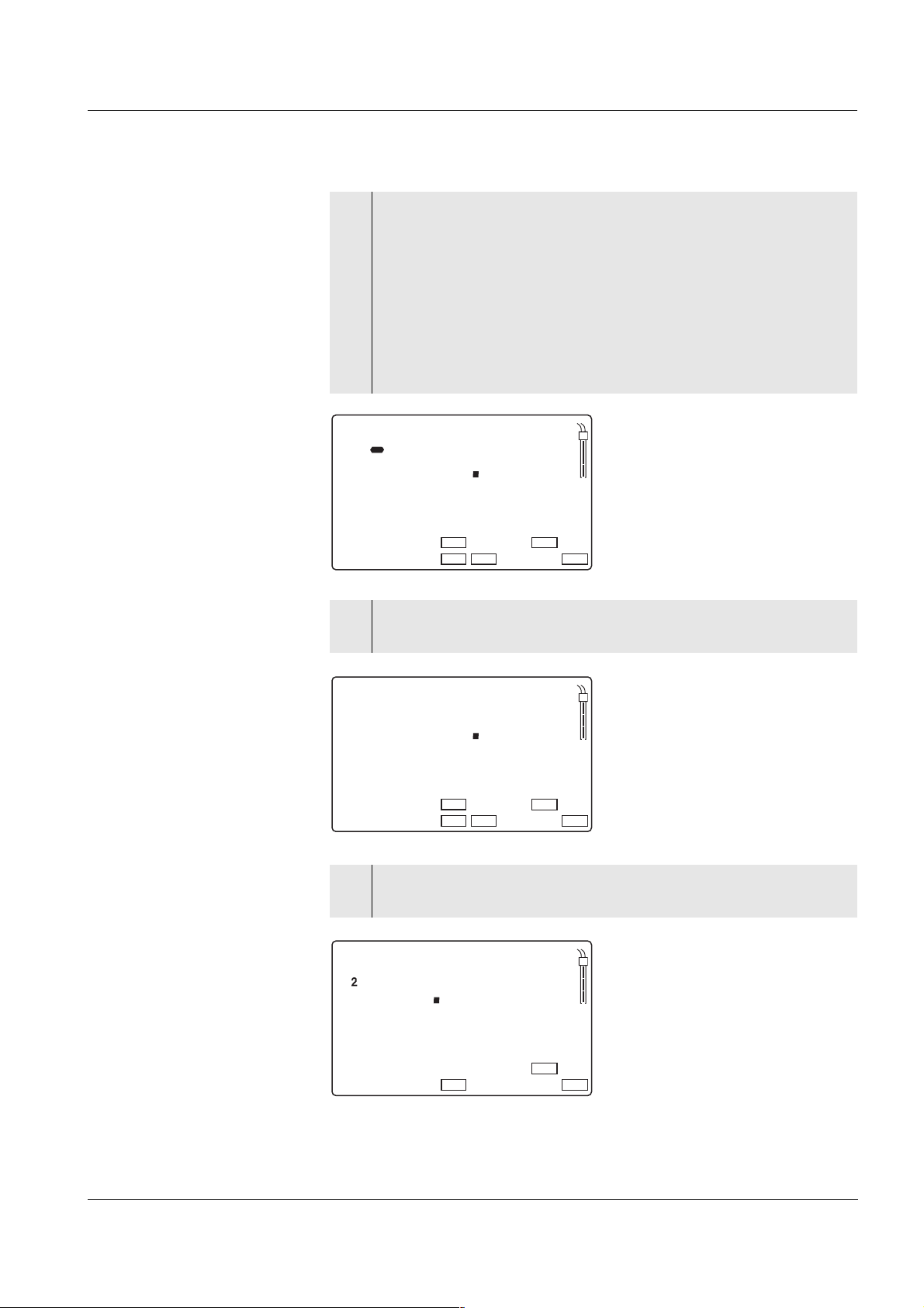
4.7.1 Saving manually
You can transmit a measured value to the data storage as follows:
1 Press the <STO> key.
The current number (location number No.) of the next free storage location appears under the current measured value on the
display.
%
m
1/
°
S/
C
pH/mV
mg/l
cm
cm
%
/
REL1
AR
K
Sal
TP
REL2
RCL
pH
O
Sal
Time
Day.Month
Year
LoBat
S
I
Baud
Ident
Tref25
nLF
No.
d 1
4
Tref20
Oxi
Lin
Auto
Cal
Store
TEC
969
4
ARng
2 Confirm with <RUN/ENTER>.
The display switches to entering the ID number.
44
Page 47

Multi 1970i Operation
Message StoFull
StoFull This message appears when all of the 500 storage locations are occu-
StoFullStoFull
m
%
1/
°
mg/l
S/
cm
%
C
REL1
AR
pH/mV
cm
Sal
K
/
REL2
TP
RCL
pH
O
Sal
Time
Day.Month
Year
LoBat
S
I
Baud
No.
Ident
Tref25
nLF
d 1
4
Tref20
Auto
Cal
Oxi
Lin
Store
TEC
969
2
ARng
3 Using <▲> <▼>, enter the required ID number
(1 ... 999).
4 Confirm with <RUN/ENTER>.
The measured values are stored. The instrument changes to
the measuring mode.
pied.
You have the following options:
Saving the current measured value.
The oldest measured value (storage location 1)
will be overwritten by this
Press
<RUN/ENTER>
Returning to the measuring mode without saving press any key
Outputting the data storage see
section 4.7.3
Clearing the memory see
section 4.7.4
45
Page 48

Operation Multi 1970i
4.7.2 Switching on AutoStore (Int 1)
The save interval (Int 1) determines the chronological interval between
automatic save processes. After the fixed interval has expired, the current data record is transmitted to the internal storage and to the interface.
Switching on AutoStore
1 Press the <RUN/ENTER> key and hold it down.
2 Press the <STO> key. Int 1 appears on the display.
%
m
1/
°
S/
C
pH/mV
mg/l
cm
cm
%
/
REL1
AR
K
Sal
TP
REL2
RCL
pH
O
Sal
Time
Day.Month
Year
LoBat
S
I
Baud
Ident
Tref25
nLF
1nt
No.
Lin
d
Tref20
Auto
Cal
Oxi
F
FO
Store
ARng
TEC
3 Set the required interval between the saving procedures with
<▲> <▼> (selection: 5 s, 10 s, 30 s, 1 min, 5 min, 10 min,
15 min, 30 min, 60 min).
4 Confirm with <RUN/ENTER>.
The number of free memory locations appears on the display.
%
m
1/
°
S/
C
pH/mV
mg/l
cm
cm
%
/
REL1
AR
K
Sal
TP
REL2
RCL
pH
O
Sal
Time
Day.Month
Year
LoBat
S
I
Baud
Ident
Tref25
nLF
949
No.
E
ER
Store
Auto
Cal
Oxi
TEC
ARng
Lin
F
Tref20
46
5 Confirm with <RUN/ENTER>.
The prompt for the ID number appears on the display.
Page 49

Multi 1970i Operation
m
%
1/
°
mg/l
S/
cm
%
C
REL1
AR
pH/mV
cm
Sal
K
/
REL2
TP
RCL
pH
O
Sal
Time
Day.Month
Year
LoBat
S
I
Baud
Ident
Tref25
nLF
949
No.
ERF
Store
TEC
1
ARng
Lin
Tref20
Auto
Cal
Oxi
6 Set the required ID number with <▲> <▼>.
7 Confirm with <RUN/ENTER>.
The measuring instrument switches to the last active measuring mode and start the measuring and saving procedure. Au-
toStore flashes on the display.
As soon as all of the 500 storage locations are occupied, AutoStore is
terminated (Int 1 = OFF). If there are not enough storage locations
available for your measurements:
z Output and backup the data storage (see page 48) and
z clear the memory (see page 54).
Note
The AutoStore function is interrupted if you start other functions, e.g.
output the data storage. After the other function is finished, the AutoStore function is continued. By this, however, temporal gaps in the recording of the measured values will occur.
Switching off AutoStore Switch AutoStore off by:
z setting the save interval (Int 1) to OFF, or
z switching the measuring instrument off and then on again.
47
Page 50

Operation Multi 1970i
4.7.3 Outputting the data storage
You can output the contents of the data storage:
z Stored data on the display
z Calibration data on the display
z Stored data on the serial interface
z Calibration protocol on the interface
Outputting stored data
on the display
1 Press the <RCL> key repeatedly until StO dISP appears on the
display.
%
m
1/
°
S/
C
pH/mV
mg/l
cm
cm
%
/
REL1
AR
K
Sal
TP
REL2
RCL
pH
O
Sal
Time
Day.Month
Year
LoBat
S
I
Baud
Ident
Tref25
nLF
oST
No.
SID
P
Store
Auto
Tref20
Cal
Oxi
Lin
TEC
ARng
2 Press the <RUN/ENTER> key.
A measured value appears on the display.
The storage location of the data record is displayed for approx.
2 s, then the respective temperature appears.
m
%
1/
°
mg/l
S/
cm
%
C
REL1
AR
pH/mV
cm
K
/
REL2
Sal
TP
RCL
pH
S
O
Sal
1
Time
Day.Month
Year
LoBat nLF
6
Baud
No.
Ident
8
Tref25 Tref20
Lin
03
2 5 0
Auto
Store
Oxi
Cal
TEC
ARng
48
You can perform the following activities:
Display further data of the data record
Press <RUN/ENTER>
(ID number, date, time, storage location)
Toggle between two saved measured variables
Press <RUN/EN-
TER> + <M>
Advance one data record (storage location) Press <▲>
Go back one data record (storage location) Press <▼>
Page 51

Multi 1970i Operation
Note
If you want to search for a certain element of the data record (e.g. date),
proceed as follows:
1 Using <RUN/ENTER>, select the element (e.g. date).
2 Press <▲> or <▼> repeatedly until the required element ap-
pears on the display.
After approx. 2 s the temperature of the displayed measured
value appears.
Outputting stored data
to the interface
1 Press the <RCL> key repeatedly until Sto SEr appears on the
display.
m
%
1/
°
mg/l
S/
cm
%
C
REL1
AR
pH/mV
cm
Sal
K
/
REL2
TP
RCL
pH
O
Sal
Time
Day.Month
Year
LoBat
S
I
Baud
Ident
Tref25
nLF
oST
No.
Lin
D
Tref20
ES
r
Store
Auto
Cal
Oxi
TEC
ARng
2 Press the <RUN/ENTER> key.
The complete contents of the storage are transmitted to the interface. During the data transmission the instrument increments the storage numbers. After the data transmission, the
instrument automatically switches to the last active measurement mode.
The transmitted data contains the entire contents of the storage in incrementing order of the location numbers.
Note
You can cancel the transmission with <M> or <RUN/ENTER>.
49
Page 52

Operation Multi 1970i
Sample printout:
No. 1:
09.03.02 17:10
pH 10.01 25 °C
Tauto AR
Ident : 47
No. 2:
09.03.02 17:12
305 mV
Tauto
Ident : 6
No. 3:
09.03.02 17:24
7.88 mg/l 17.6° C
Tauto
Ident : 81
No. 4:
09.03.02 17:46
7.11 mg/l 17.8° C
Tauto
SAL = 17.9
Ident : 4
Outputting the calibra-
tion data
on the display
No. 5:
10.03.02 19:09
2.40 mS/cm 25.3 °C
Tauto
nLF
Tref25 C = 0.475 1/cm
Ident : 10
No. 6:
10.03.02 20:48
2.46 mS/cm 25.6 °C
Tauto
nLF
Tref25 C = 0.475 1/cm
Ident : 1
...
1 Press the <RCL> key repeatedly until CAL disp appears on
the display.
%
m
1/
°
S/
C
pH/mV
mg/l
cm
cm
%
/
REL1
AR
K
Sal
TP
REL2
RCL
pH
S
O
Sal
C
Time Baud
Day.Month
Year
LoBat
C
No.
Ident
d
Tref25 Tref20
Lin
nLF
AL
I S P
Auto
Oxi
Cal
Store
TEC
ARng
50
Page 53
Multi 1970i Operation
2 Press the <RUN/ENTER> key.
The data of the last calibration of all measured variables appears in the following sequence:
z pH: Slope SLO and asymmetry ASY
z Oxygen: Relative slope SLO
z Cond: Cell constant C
Information concerning the calibration procedure is output as
well.
pH/
Store
TEC
ARng
mV
%
m
1/
°
mg/l
S/
cm
%
C
REL1
AR
cm
Sal
K
/
REL2
TP
RCL
pH
S
O
Sal
1
Time
Day.Month
Year
LoBat nLF
594
Baud
No.
Ident
8
Lin
Oxi
S L O
Auto
Cal
Tref25 Tref20
3 Press <RUN/ENTER> to display the value of the asymmetry
(mV).
pH/
Store
TEC
Store
TEC
ARng
0
ARng
mV
%
m
1/
°
mV
%
m
1/
°
mg/l
S/
cm
%
C
REL1
AR
mg/l
S/
cm
%
C
REL1
AR
cm
Sal
K
/
REL2
pH/
cm
Sal
K
/
REL2
TP
RCL
TP
RCL
pH
S
O
Sal
Time
Day.Month
Year
LoBat nLF
4 Press <RUN/ENTER> to display the relative slope of the D. O.
pH
1
Baud
No.
Ident
Tref25 Tref20
Lin
sensor.
S
5
8
A S Y
Oxi
01
Auto
Cal
O
Sal
1
Time
Day.Month
Year
Tref25 Tref20
LoBat nLF
Baud
No.
Ident
0
8
Lin
Oxi
88
S L
Auto
Cal
51
Page 54

Operation Multi 1970i
5 Press <RUN/ENTER> to display the cell constant. The dis-
played value is:
z the current, calibrated cell constant (with sensor symbol on
the display) or
z the fixed cell constant 0.475 1/cm (without sensor symbol
on the display). In this case, the measuring parameters are
pH
S
O
Sal
1
Time
Day.Month
Year
LoBat nLF
initialized (see section 4.10 R
/pH
mV
mg/l
%
m
S/
Baud
No.
Ident
0 4 7 2
Tref20
Tref25
Lin
Oxi
LCLC
C
Auto
ARng
TEC
Cal
1/
°
cm
%
C
AR
cm
/
Sal
K
REL2
RCL RCL
ESET).
pH
O
Sal
1
Time
Day.Month
Year
LoBat nLF
Baud
Ident
Tref25
mVS/
pH
mg/l
%
m
S/
ARng
1/
°
cm
%
C
REL1REL1
AR
cm
K
/
Sal
TPTP
REL2
C
No.
4 7 5
0
Auto
Tref20
Lin
Oxi
TEC
Cal
6 With <M> you can switch back to the last active measuring
mode.
52
Page 55
Multi 1970i Operation
Outputting the calibra-
tion protocol on the
interface
1 Press the <RCL> key repeatedly until CAL SEr appears on the
display.
m
%
1/
°
mg/l
S/
cm
%
C
REL1
AR
pH/mV
cm
Sal
K
/
REL2
TP
RCL
pH
S
O
Sal
C
Time Baud
Day.Month
Year
LoBat
C
No.
Ident
d
Tref25 Tref20
Lin
nLF
AL
S E R
Auto
Oxi
Cal
Store
TEC
ARng
2 Press the <RUN/ENTER> key.
The calibration protocol for all measured variables is transmitted to the interface. After the data transmission, the instrument
automatically switches to the last active measurement mode.
Sample printout:
CALIBRATION PROTOCOL
02.03.02 14:19
Device No.: 12345678
Calibration pH
Cal time: 01.03.02 / 15:20
Cal interval: 7d
AutoCal TEC Tauto
Buffer 1 2.00
Buffer 2 4.01
Buffer 3 7.00 *
Buffer 4 10.01
C1 174.1 mV 25.0°C
C2 -133.3 mV 25.0°C
S1 -59.4 mV/pH
ASY1 - 4 mV
Probe: +++
CALIBRATION 02
Cal time: 02.03.02 / 14:19
Cal interval: 14d
OxiCal Tauto AR
Relative Slope: 0,88
Probe: +++
Calibration Conductivity
Cal time: 14.01.02 / 11:37
Cal interval: 180d
Cal Std.: 0.01 mol/l KCL
40.0 °C
Conduct./Tref25: 1413µS/cm
Cell Const : 0.478 1/cm
Probe : +++
53
Page 56

Operation Multi 1970i
4.7.4 Clearing the memory
With this function, you can delete the stored data records. 500 storage
locations will then be available again.
Note
The Clear memory function only appears when there are data records
stored in the memory. Otherwise, the measuring instrument automatically switches to the last active measuring mode.
Proceed as follows to clear all data records:
1 Switch off the measuring instrument.
2 Press the <STO> key and hold it down.
3 Press the <ON/OFF> key.
The display test appears briefly on the display.
m
%
1/
°
mg/l
S/
cm
%
C
REL1
AR
pH/mV
cm
K
/
REL2
Sal
TP
RCL
pH
S
O
Sal
Time Baud
Day.Month
Year
LoBat
4 Confirm the clearing process with <RUN/ENTER>.
Note
The calibration data remain stored and can be called up.
S
Lin
d
Oxi
To
C L R
Auto
Store
TEC
ARng
Cal
C
No.
Ident
Tref25 Tref20
nLF
Pressing any other key prevents the clearing, the data records
will remain stored.
54
Page 57

Multi 1970i Operation
4.8 Transmitting data
You have the following possibilities of transmitting data:
z One of the following options:
– With the AutoStore function (page 46), the measured values of all
connected and active sensors are stored periodically and output
to the interface (save interval Int 1).
– With the Data transmission interval (Int 2), the measured values
of all connected and active sensors are periodically output to the
interface (see below).
– AutoStore (Int 1) covers the Data transmission interval
(Int 2).
z Press the <RUN/ENTER> key
This manually triggers a data transmission of the current measured
value to the serial interface at any time - independently of the selected intervals.
Setting the
Data transmission
interval
z With the Output data storage function (page 48), calibration data or
saved measured values are output on the interface.
4.8.1 Data transmission interval (Int 2)
The interval for the data transmission (Int 2) determines the chronological interval between automatic data transmissions. After the selected
interval expires, the current data record is transmitted to the interface.
The default setting for the interval is OFF.
To start the data transmission, set an interval (5 s, 10 s, 30 s, 1 min,
5 min, 10 min, 15 min, 30 min, 60 min):
1 Press the <RUN/ENTER> key and hold it down.
2 Press the <RCL> key. Int 2 appears on the display.
m
%
1/
°
mg/l
S/
cm
%
C
REL1
AR
pH/mV
cm
Sal
K
/
REL2
TP
RCL
pH
S
O
Sal
I
Time Baud
Day.Month
Year
LoBat
n
No.
Ident
d
Tref25 Tref20
Lin
nLF
T2
O F F
Store
Auto
Oxi
Cal
TEC
ARng
3 Set the required interval between the saving procedures with
<▲> <▼>.
55
Page 58

Operation Multi 1970i
4 Confirm with <RUN/ENTER>.
The measuring instrument switches to the last active measuring mode.
Note
When the AutoStore function is active at the same time, the data transmission is performed according to the setting of the save interval (Int 1).
Set the save interval (Int 1) to OFF to activate the Data transmission in-
terval (Int 2).
56
Page 59
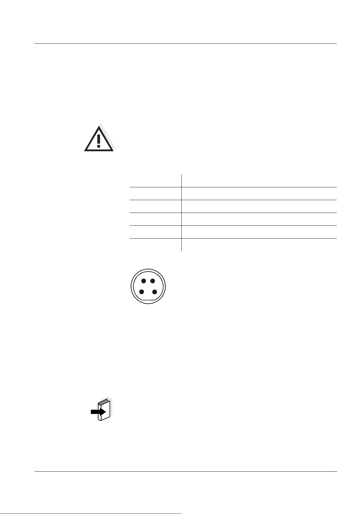
Multi 1970i Operation
S
4.8.2 PC/external printer (RS232 interface)
Via the RS 232 interface, you can transmit the data to a PC or an external printer.
Use the AK340/B (PC) or AK325/S (ext. printer) cable to connect the
interface to the devices.
Warning
The RS232 interface is not galvanically isolated.
When connecting an earthed PC/printer, measurements cannot be performed in earthed media as incorrect values would result.
Set up the following transmission data at the PC/printer:
Baud rate selectable between: 1200, 2400, 4800, 9600
Handshake RTS/CTS + Xon/Xoff
PC only:
Socket assignment
Parity none
Data bits 8
Stop bits 2
1 CT
2 RxD
2
1
4
3
RS 232
REC
4.8.3 Remote control
The measuring instrument can be remotely controlled from a PC. This
requires the KOM pilot communication kit. It is available as an accessory. The instrument is then controlled via commands that simulate
keystrokes and request the current display contents.
3 Ground
4TxD
Note
A more detailed description is provided within the scope of delivery of
the communication kit.
57
Page 60

Operation Multi 1970i
4.9 Configuration
You can adapt the measuring instrument to your individual requirements. To do this, the following parameters can be changed (the status
on delivery is marked in bold):
Baud rate 1200, 2400, 4800, 9600
Air pressure display Current value in mbar
(no input possible)
Baudrate
Calibration
intervals
– pH: 1 ... 7 ... 999 dInt 3
1 ... 14 ... 999 dInt 4
– O
2
– : 1 ... 180 ... 999 dInt 5
Date/time Any
Note
You can leave the configuration menu at any time with <M> . The parameters that have already been changed are stored.
1 Switch off the measuring instrument.
2 Press the <M> key and hold it down.
3 Press the <ON/OFF> key.
The display test appears briefly on the display. The measuring
instrument then switches automatically to the setting of the
baud rate.
m
%
1/
°
mg/l
S/
cm
%
C
REL1
AR
pH/mV
cm
K
/
REL2
Sal
TP
RCL
pH
O
Sal
Time
Day.Month
Year
LoBat
S
Baud
No.
Ident
Tref25 Tref20
Lin
nLF
8 0 0
4
Auto
Oxi
Cal
Store
TEC
ARng
58
4 Select the required baud rate with <▲> <▼>.
5 Confirm with <RUN/ENTER>. CAL dISP appears on the dis-
play.
Page 61

Multi 1970i Operation
Display during the
pH calibration
Displaying the
air pressure
mV
%
m
1/
°
mV
%
m
1/
°
mg/l
S/
cm
%
C
REL1
AR
mg/l
S/
cm
%
C
REL1
AR
pH/
cm
Sal
K
/
REL2
pH/
cm
Sal
K
/
REL2
TP
RCL
TP
RCL
pH
S
O
Sal
Time Baud
Day.Month
Year
LoBat
6 Select the required display during the pH calibration with
7 Confirm with <RUN/ENTER>. P appears on the display.
The air pressure in mbar is only displayed if a D. O. sensor is connected
to the active REL socket. Otherwise, "---" appears.
pH
C
Lin
d
Oxi
AL
I S P
Store
Auto
TEC
ARng
Cal
C
No.
Ident
Tref25 Tref20
nLF
<▲> <▼>.
mV: Display of the current electrode voltage
/pH: Display of the buffer nominal value.
S
O
Sal
Time Baud
Day.Month
Year
LoBat
C
No.
Ident
Tref25 Tref20
Lin
nLF
CA
d
9 4 9
Auto
Store
Cal
Oxi
TEC
P
ARng
pH calibration interval
8 Confirm with <RUN/ENTER>. Int 3 and the measured variable
pH appear on the display.
m
%
1/
°
mg/l
S/
cm
%
C
REL1
AR
pH/mV
cm
Sal
K
/
REL2
TP
RCL
pH
S
O
Sal
I
Baud
Time
Day.Month
LoBat
10 Confirm with <RUN/ENTER>. Int 4 and the measured variable
No.
Year
Ident
d
Tref25
Tref20
nLF
Oxi
Lin
9 Set the required interval in days (d) with <▲> <▼>.
appear on the display.
O
2
4
Auto
3nt
1
7
Store
ARng
TEC
Cal
59
Page 62
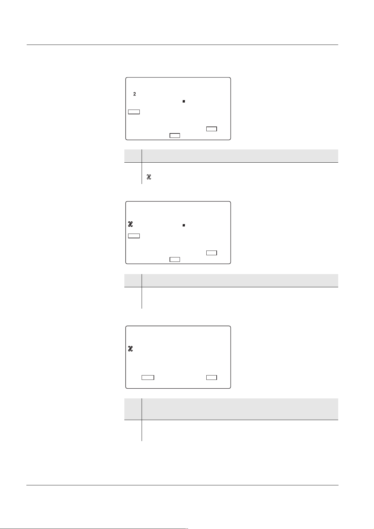
Operation Multi 1970i
Dissolved oxygen
calibration interval
Conductivity
calibration interval
m
%
1/
°
mg/l
S/
cm
%
C
REL1
AR
pH/mV
cm
K
/
REL2
Sal
TP
RCL
pH
O
Sal
Time
Day.Month
Year
LoBat
S
I
Baud
Ident
Tref25
nLF
4nt
No.
4
1 4
Auto
Store
Oxi
Cal
TEC
ARng
Lin
d
Tref20
11 Set the required interval in days (d) with <▲> <▼>.
12 Confirm with <RUN/ENTER>. Int 5 and the measured variable
appears on the display.
m
%
1/
°
mg/l
S/
cm
%
C
REL1
AR
pH/mV
cm
K
/
REL2
Sal
TP
RCL
pH
O
Sal
Time
Day.Month
Year
LoBat
S
I
Baud
Ident
Tref25
nLF
5nt
No.
8 0
1
Auto
Store
Oxi
Cal
TEC
ARng
Lin
d
Tref20
Switching over the
reference temperature
13 Set the required interval in days (d) with <▲> <▼>.
14 Confirm with <RUN/ENTER>. The reference temperature set
for conductivity measurements appears on the display.
m
%
1/
°
mg/l
S/
cm
%
C
REL1
AR
pH/mV
cm
K
/
REL2
Sal
TP
RCL
pH
O
Sal
Time
Day.Month
Year
LoBat
S
I
Baud
Ident
Tref25
nLF
5t2
No.
Tref20
Lin
8 0d 1
Auto
Store
Cal
Oxi
TEC
ARng
15 Using <▲> <▼>, toggle between 25 °C (Tref25) and 20 °C
(Tref20).
16 Confirm with <RUN/ENTER>.
The date flashes on the display.
60
Page 63

Multi 1970i Operation
Date and time
m
%
1/
°
mg/l
S/
cm
%
C
REL1
AR
pH/mV
cm
Sal
K
/
REL2
TP
RCL
pH
O
Sal
Time
Day.Month
Year
LoBat
S
I
Baud
No.
Ident
0 9 0 4
Tref25
Tref20
nLF
Lin
5t2
Auto
Store
Cal
Oxi
TEC
ARng
17 Set the date of the current day with <▲> <▼>.
18 Confirm with <RUN/ENTER>.
The date (month) flashes in the display.
19 Set the current month with <▲> <▼>.
20 Confirm with <RUN/ENTER>.
The year appears on the display.
21 Set the current year with <▲> <▼>.
22 Confirm with <RUN/ENTER>.
The hours flash on the display.
23 Set the current time with <▲> <▼>.
24 Confirm with <RUN/ENTER>.
The minutes flash on the display.
25 Set the current time with <▲> <▼>.
26 Confirm with <RUN/ENTER>.
The measuring instrument switches to the last active measuring mode.
61
Page 64
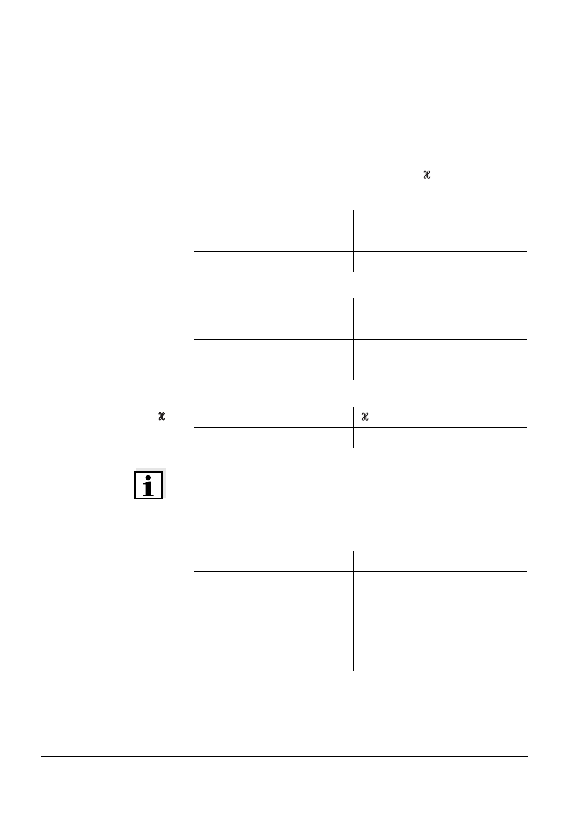
Operation Multi 1970i
4.10 Reset
You can reset (initialize) the measurement parameters and the configuration parameters separately from one another.
Measurement
parameters
pH
O
The following measurement parameters (pH/O
/ InI) can be reset to
2
the delivery status:
Measuring mode pH
Asymmetry 0 mV
Slope -59.16 mV
2
Measuring mode D. O. concentration
Relative slope 1.00
Salinity (value) 0.0
Salinity (function) Off
Measuring mode
-1
Cell constant 0.475 cm
(fixed)
Configuration
parameters
Note
The calibration data gets lost when the measuring parameters are reset. Recalibrate after performing a reset.
The following configuration parameters (InI) are reset to the delivery
status:
Baud rate 4800
Display during the
Buffer nominal value
pH calibration
Interval 1
(automatically saved) OFF
Interval 2
(for data transmission) OFF
62
Page 65

Multi 1970i Operation
Resetting the
measuring parameters
1 Press the <RUN/ENTER> key and hold it down.
2 Press the <CAL> key. The setting to reset the pH measuring
parameters appears on the display.
m
%
1/
°
mg/l
S/
cm
%
C
REL1
AR
pH/mV
cm
Sal
K
/
REL2
TP
RCL
pH
O
Sal
Time
Day.Month
Year
LoBat
S
I
Baud
Ident
Tref25
nLF
No.
0 9
Tref20
Lin
iin
n o
Auto
Store
Cal
Oxi
TEC
ARng
3 Using <▲> <▼>, switch between no and YES.
YES: Resetting the pH measuring parameters
no: Retaining settings.
4 Confirm with <RUN/ENTER>.
The measuring instrument switches to the setting to reset the
O
measuring parameters.
2
m
%
1/
°
mg/l
S/
cm
%
C
REL1
AR
pH/mV
cm
Sal
K
/
REL2
TP
RCL
pH
O
Sal
Time
Day.Month
Year
LoBat
S
I
Baud
Ident
Tref25
nLF
No.
0 9
Tref20
Lin
iin
n o
Auto
Store
Cal
Oxi
TEC
ARng
5 Using <▲> <▼>, switch between no and YES.
YES: Resetting the O
measuring parameters.
2
no: Retaining settings.
6 Confirm with <RUN/ENTER>. The measuring instrument
switches to the setting to reset the Cond measuring parameters.
63
Page 66

Operation Multi 1970i
%
m
1/
°
S/
C
pH/mV
mg/l
cm
cm
%
/
REL1
AR
K
Sal
TP
REL2
RCL
pH
O
Sal
Time
Day.Month
Year
LoBat
S
I
Baud
Ident
Tref25
nLF
No.
0 9
Lin
Tref20
iin
n o
Auto
Store
Cal
Oxi
TEC
ARng
7 Using <▲> <▼>, switch between no and YES.
YES: Resetting the Cond measuring parameters.
no: Retaining settings.
8 Confirm with <RUN/ENTER>.
The measuring instrument switches to the configuration parameters.
m
%
1/
°
mg/l
S/
cm
%
C
REL1
AR
pH/mV
cm
K
/
REL2
Sal
TP
RCL
pH
O
Sal
Time
Day.Month
Year
LoBat
S
I
Baud
Ident
Tref25
nLF
No.
0 9
Tref20
Lin
iin
n o
Auto
Store
Cal
Oxi
TEC
ARng
Resetting the
configuration parame-
ters
9 Using <▲> <▼>, switch between no and YES.
YES: Resetting the configuration parameters
no: Retaining settings.
10 Confirm with <RUN/ENTER>.
The measuring instrument switches to the last active measuring mode.
64
Page 67

Multi 1970i Maintenance, cleaning, disposal
5 Maintenance, cleaning, disposal
5.1 Maintenance
The measuring instrument is maintenance-free.
5.2 Cleaning
Occasionally wipe the outside of the measuring instrument with a
damp, lint-free cloth. Disinfect the housing with isopropanol as required.
Warning
The housing components are made out of synthetic materials (polyurethane, ABS and PMMA). Thus, avoid contact with acetone and similar
detergents that contain solvents. Remove any splashes immediately.
5.3 Disposal
Packing This measuring instrument is sent out in a protective transport packing.
We recommend: Keep the packing material. The original packing protects the measuring instrument from transport damages.
Rechargeable battery Remove the rechargeable battery from the instrument and dispose of it
at a suitable facility according to local legal requirements. It is illegal to
dispose of the rechargeable battery with household refuse. Proceed as
follows to disassemble the rechargeable battery:
1
Ni-Cd Cd
1
1 Remove the carrying and positioning handle or the carrying
strap.
2
2 Unscrew the fixing elements (1) using a hexagon key.
3 Remove the instrument from the enclosure by vigorously
pressing against the socket field.
4 Take out the rechargeable battery (2) and cut off the battery ca-
ble.
65
Page 68

Maintenance, cleaning, disposal Multi 1970i
Measuring instrument Dispose of the measuring instrument without the rechargeable battery
as electronic waste at an appropriate collection point.
66
Page 69

Multi 1970i What to do if...
6 What to do if...
6.1 pH system messages
Error message 0FL
0FL
0FL0FL
Cause Remedy
pH electrode:
– Not connected – Connect electrode
Error message E3
E3
E3E3
– Air bubble in front of the
– Remove air bubble
diaphragm
– Air in the diaphragm – Extract air or
moisten diaphragm
– Cable broken – Replace electrode
– Gel electrolyte dried out – Replace electrode
Cause Remedy
Electrode
– Diaphragm contaminated – Clean diaphragm
– Membrane contaminated – Clean membrane
– Moisture in the plug – Dry plug
– Electrolyte obsolete – Replenish electrolyte or
replace electrode
– Electrode obsolete – Replace electrode
– Electrode broken – Replace electrode
Measuring instrument:
– Incorrect calibration procedure – Select correct procedure
– Incorrect solution temperature
– Set up correct temperature
(without temperature sensor)
– Socket damp – Dry socket
67
Page 70

What to do if... Multi 1970i
Buffer solutions
– Incorrect buffer solutions – Change calibration procedure
– Buffer solutions too old – Use only once.
Note the shelf life
– Buffer solutions depleted – Change solutions
No stable measured
Cause Remedy
value
pH electrode:
– Diaphragm contaminated – Clean diaphragm
– Membrane contaminated – Clean membrane
Obviously incorrect
measured values
Test sample:
– pH value not stable – Measure with air excluded if
necessary
– Temperature not stable – Adjust temperature if
necessary
Electrode + test sample:
– Conductivity too low – Use suitable electrode
– Temperature too high – Use suitable electrode
– Organic liquids – Use suitable electrode
Cause Remedy
pH electrode:
– pH electrode unsuitable – Use suitable electrode
– Temperature difference
between buffer and test
– Adjust temperature of buffers
or sample
sample too high
68
– Measurement procedure not
suitable
– Follow special procedure
Page 71

Multi 1970i What to do if...
6.2 Oxi system messages
Error message 0FL
Error message E3
0FL
0FL0FL
E3
E3E3
Cause Remedy
Display range exceeded
Oxygen sensor
– Not connected – Connect the sensor
– Cable broken – Replace sensor
– Depleted – Replace sensor
– Short-circuit between gold and
lead electrode
– Clean sensor and replace it if
necessary
Cause Remedy
Invalid calibration
Oxygen sensor
– Electrolyte solution depleted – Regenerate sensor
– Membrane contaminated – Clean membrane
Error message E7
E7
E7E7
AR flashes
continuously
– Electrode system poisoned – Regenerate sensor
– Obsolete – Replace sensor
– Broken – Replace sensor
Cause Remedy
Membrane damaged
– Membrane damaged – Regenerate sensor
– Membrane head screwed on
– Screw membrane head tight
not tight enough
Cause Remedy
No stable measured value
– Membrane contaminated – Clean membrane
69
Page 72

What to do if... Multi 1970i
Measured value too low
Measured value too
high
Error message OFL
OFL
OFLOFL
Cause Remedy
– Insufficient flow – Provide flow to the sensor
Cause Remedy
– High amount of dissolved
substances
– Air bubbles bump on the
membrane with high velocity
– The carbon dioxide pressure is
– Correct solubility function
using the salinity equivalent
– Avoid direct flow to the
membrane
– Measuring not possible
too high (> 1 bar)
6.3 Conductivity system messages
Cause Remedy
Error message E3
E3
E3E3
The measured value lies outside
the measuring range
– Measuring cell not connected – Connect measuring cell
– Cable broken – Replace measuring cell
Cause Remedy
– Measuring cell contaminated – Clean cell and replace it if
necessary
– Unsuitable calibration
– Check calibration solutions
solution
70
Page 73

Multi 1970i What to do if...
6.4 General errors
Display LoBat
Instrument does not
react
to keystroke
Display to
to
toto
Cause Remedy
– Battery almost empty – Charge the battery (see
section 3.2)
Cause Remedy
– Operating condition undefined
or EMC load unallowed
– Processor reset:
Switch the instrument on
while pressing the <RCL> key
Cause Remedy
Sensor symbol flashes
Message StoFull
StoFull
StoFullStoFull
You want to know which
software version is in
the instrument
– Time-out of the interface – Check the instrument
connected
Cause Remedy
– Calibration interval expired – Recalibrate the measuring
system
Cause Remedy
– All memory locations are full – Output data storage and clear
data storage
Cause Remedy
– E. g., a question by the WTW
service department
– Simultaneously press the
<CAL> and <ON/OFF> keys
and release them again. The
software version is displayed.
71
Page 74

What to do if... Multi 1970i
72
Page 75

Multi 1970i Technical data
7 Technical data
7.1 General data
Dimensions approx. 90 x 200 x 190 mm
Weight approx. 1.5 kg (without plug-in power supply)
Mechanical structure Type of protection IP 67
Electrical safety Protective class III
Test certificates CE
Ambient conditions Storage - 25 °C ... + 65 °C
Operation -10 °C ... + 55 °C
Climatic class 2
Power
supply
Rechargeable battery Nickel-cadmium(NiCad) rechargeable bat-
tery
Operational life approx. 600 hours with one charging
Plug-in power supply
unit
(charging device)
The following applies to all plug-in power
supplies:Connection max.
Overvoltage category II
Plug-in power supply unit
(Euro, US , UK, Australian plug)
FRIWO FW7555M/09, 15.1432
Friwo Part. No. 1883259
Input: 100 ... 240 V ~ / 50 ... 60 Hz / 400 mA
Output: 9 V = / 1,5 A
73
Page 76

Technical data Multi 1970i
Serial
interface
Guidelines
and norms used
Connection of the cable AK 340/B or AK 325/S
Baud rate adjustable: 1200, 2400, 4800, 9600 Baud
Type RS232, data output
Data bits 8
Stop bits 2
Parity None
Handshake RTS/CTS + Xon/Xoff
Cable length Max. 15m
EMC EC guideline 89/336/EEC
EN 61326-1:1998
EN 61000-3-2 A14:2000
EN 61000-3-3:1995
FCC Class A
Instrument safety E.C. guideline 73/23/EEC
EN 61010-1 A2:1995
Manual
temperature input
Climatic class VDI/VDE 3540
IP protection EN 60529:1991
7.2 Measuring ranges, resolutions, accuracies
7.2.1 pH/ORP
Variable Measuring
range
pH - 2.00 ... + 19.99 0.01 ± 0.01 *
U [mV] - 1999 ... + 1999 1 ± 1
T [°C] - 5.0 ... + 105.0 0.1 ± 0.1
* when measuring in a range of ± 2 pH around a calibration point
Variable Range Increment
T
[°C] - 20 ... + 130 1
manual
Resolution Accuracy
(± 1 Digit)
74
Page 77

Multi 1970i Technical data
7.2.2 Dissolved oxygen
Measuring ranges
and resolutions
Accuracies Variable Accuracy (± 1 Digit)
Correction
functions
Variable Measuring range Resolution
Concentration [mg/l] 0 ... 19.99
0 ... 90.0
Saturation [%] 0 ... 199.9
0 ... 600
0.01
0.1
0.1
1
T [°C] 0 ... 50.0 0.1
Concentration [mg/l] ± 0.5 % of measured value
at ambient temperature of 5 °C ... 30 °C
Saturation [%] ± 0.5 % of measured value
when measuring in the range of ± 10 K
around the calibration temperature
T [°C] ± 0.1
Temperature com-
Accuracy better than 2 % at 0 ... 40 °C
pensation
Salinity correction 0 ... 70.0 SAL
Air pressure
correction
Automatic through integrated pressure sensor in the range of 500 ... 1100 mbar
75
Page 78
Technical data Multi 1970i
7.2.3 Conductivity
Measuring ranges
and resolutions
Accuracies Variable Accuracy (± 1 Digit)
Variable Measuring range Resolution
[µS/cm] 0 ... 1999 1
[mS/cm] 0.00 ... 19.99
0.0 ... 199.9
0 ... 500
SAL 0.0 ... 70.0
0.01
0.1
1
0.1
according to the IOT
table
T [°C] − 5.0 ... + 105.0 0.1
[µS/cm] / [mS/cm]
Accuracy Sample temperature
± 0.5 % 0 °C ... 35 °C
(nonlinear compensation)
± 0.5 % 35 °C ... 50 °C
according to EN 27 888;
extended nLF function
according to
WTW measurements
Cell constant,
calibrating
Reference
temperature
SAL
Accuracy Sample temperature
± 0.1 5 °C ... 25 °C
(range 0.0 ... 42.0)
± 0.2 25 °C ... 30 °C
T [°C] ± 0.1
C [cm-1] 0.450 ... 0.500
Tref Can be set to 20 °C or 25 °C
76
Page 79

Multi 1970i Lists
8Lists
This chapter provides additional information and orientation aids.
Abbreviations The list of abbreviations explains the indicators and the abbreviations
that appear on the display and in the manual.
Specialist terms The glossary briefly explains the meaning of the specialist terms. How-
ever, terms that should already be familiar to the target group are not
described here.
Index The index helps you to find the topics that you are looking for.
77
Page 80

Lists Multi 1970i
Abbreviations
Conductivity value (international γ)
AR AutoRead (drift control)
ARng Automatic range switching
Measuring instrument measures with highest resolution
ASY Asymmetry
AutoCal DIN Automatic pH calibration with buffer solutions pre-
pared according to DIN 19 266
AutoCal TEC Automatic pH calibration with WTW technical buff-
er solutions according to DIN 19267
-1
C Cell constant [cm
] (internat. k)
°C Temperature unit, degrees Celsius
Cal Calibration
Cd... Display indicator during calibration for pH mea-
surements. Indicates the selection of the buffer
data record for buffer solutions prepared according
to DIN 19 266
Cm... Display indicator during calibration for pH mea-
surements. Indicates the selection of buffer data
records for buffer solutions of the Merck company
ConCal Conventional single-point or two-point calibration
for pH measurements
Ct... Display indicator during calibration for pH mea-
surements. Indicates the selection of the buffer
data records for WTW technical buffer solutions
E3 Error message
see chapter 6 W
HAT TO DO IF...
InI Initialization
Resets individual basic functions to the status they
had on delivery
78
LoBat Battery nearly empty (Low Battery)
mV Voltage unit
mV/pH Unit of the electrode slope (internat. mV)
Page 81

Multi 1970i Lists
nLF Nonlinear temperature compensation
OFL Display range exceeded (Overflow)
OxiCal Automatic calibration for D. O. measurements
pH pH value
S Slope (internat. k)
SAL Salinity
SELV Safety Extra Low Voltage
SLO Slope setting on calibration
TC Temperature coefficient (internat. α)
TP Temperature measurement active (temperature
sensor)
25/T25 Reference temperature of 25 °C
T
Ref
U
ASY
Asymmetry
79
Page 82

Lists Multi 1970i
Glossary
Adjusting To manipulate a measuring system so that the relevant value (e. g. the
displayed value) differs as little as possible from the correct value or
a value that is regarded as correct, or that the difference remains within the tolerance.
Asymmetry Designation for the offset potential of a pH electrode. It is the measur-
able potential of a symmetrical electrode, the membrane of which is
immersed in a solution with the pH of the nominal electrode zero point
(WTW electrodes: pH = 7).
AutoRange Name of the automatic selection of the measuring range.
AutoRead WTW name for a function to check the stability of the measured value.
Calibration Comparing the value from a measuring system (e. g. the displayed
value) to the correct value or a value that is regarded as correct. Often, this expression is also used when the measuring system is adjusted at the same time (see adjusting).
Cell constant, k Characteristic quantity of a conductivity measuring cell, depending on
the geometry.
Conductivity Short form of the expression, specific electrical conductivity. It is a
measured value of the ability of a substance to conduct an electric current. In water analysis, the electrical conductivity is a dimension for the
ionized substances in a solution.
D. O. partial pressure Pressure caused by the oxygen in a gas mixture or liquid.
Diaphragm The junction is a porous body in the housing wall of reference elec-
trodes or electrolyte bridges. It forms the electrical contact between
two solutions and makes electrolyte exchange more difficult. The expression, junction, is also used for ground or junction-less transitions.
Electrode zero point The zero point of a pH electrode is the pH value at which the electro-
motive force of the pH electrode at a specified temperature is zero.
Normally, this is at 25 °C.
Electromotive force of
an electrode
The electromotive force U of the electrode is the measurable electromotive force of an electrode in a solution. It equals the sum of all the
galvanic voltages of the electrode. Its dependency on the pH results
in the electrode function which is characterized by the parameters,
slope and zero point.
Measured parameter The measured parameter is the physical dimension determined by
measuring, e. g. pH, conductivity or D. O. concentration.
Measured value The measured value is the special value of a measured parameter to
be determined. It is given as a combination of the numerical value and
unit (e. g. 3 m; 0.5 s; 5.2 A; 373.15 K).
80
Page 83

Multi 1970i Lists
Measuring system The measuring system comprises all the devices used for measuring,
e. g. measuring instrument and sensor. In addition, there is the cable
and possibly an amplifier, terminal strip and armature.
Molality Molality is the quantity (in Mol) of a dissolved substance in 1000 g sol-
vent.
MultiCal
®
WTW name stating that a measuring instrument provides several calibration procedures.
Offset potential The measurable potential of a symmetrical electrode, the membrane
of which is immersed in a solution with the pH of the nominal electrode
zero point. The asymmetry is part of the offset potential.
OxiCal
®
WTW name for a procedure to calibrate D. O. measuring systems in
water vapor saturated air.
Oxygen saturation Short name for the relative D. O. saturation.
Note: The D. O. saturation value of air-saturated water and the D. O.
saturation value of oxygen-saturated water are different.
pH value The pH is a measure of the acidic or basic effect of an aqueous solu-
tion. It corresponds to the negative decadic logarithm of the molal hydrogen ions activity divided by the unit of the molality. The practical pH
value is the value of a pH measurement.
Potentiometry Name of a measuring technique. The signal (depending on the mea-
sured parameter) of the electrode is the electrical potential. The electrical current remains constant.
ORP voltage The ORP is caused by oxidizing or reducing substances dissolved in
water if these substances become effective on an electrode surface
(e. g. a gold or platinum surface).
Reference
temperature
Fixed temperature value to compare temperature-dependent measured values. For conductivity measurements, the measured value is
converted to a conductivity value at a reference temperature of 20 °C
or 25 °C.
Reset Restoring the original condition of all settings of a measuring system.
Resistance Short name for the specific electrolytic resistance. It corresponds to
the reciprocal value of the electrical conductivity.
Resolution Smallest difference between two measured values that can be dis-
played by a measuring instrument.
Salinity The absolute salinity S
of the mass of dissolved salts to the mass of the solution (in g/Kg). In
practice, this dimension cannot be measured directly. Therefore, the
practical salinity is used for oceanographic monitoring. It is determined by measuring the electrical conductivity.
of seawater corresponds to the relationship
A
81
Page 84

Lists Multi 1970i
Salt content General designation for the quantity of salt dissolved in water.
Sample Designation of the sample ready to be measured. Normally, a test
sample is made by processing the original sample. The test sample
and original sample are identical if the test sample was not processed.
Setting the
temperature
compensation
Name of a function that considers the temperature influence on the
measurement and converts it accordingly. Depending on the measured parameter to be determined, the temperature compensation
functions in different ways. For conductimetric measurements, the
measured value is converted to a defined reference temperature. For
potentiometric measurements, the slope value is adjusted to the temperature of the test sample but the measured value is not converted.
Slope The slope of a linear calibration function.
Slope (relative) Designation used by WTW in the D. O. measuring technique. It ex-
presses the relationship of the slope value to the value of a theoretical
reference sensor of the same type of construction.
Standard solution The standard solution is a solution where the measured value is
known by definition. It is used to calibrate a measuring system.
TDS Total dissolved solids
Temperature
Value of the slope of a linear temperature function.
coefficient
Temperature function Name of a mathematical function expressing the temperature behav-
ior of a test sample, a sensor or part of a sensor.
82
Page 85

Multi 1970i Index
A
Air pressure display 59
Asymmetry 21
Authorized use 9
AutoCal TEC 21, 24
AutoRead
Conductivity
Criteria 31
Oxygen 31
pH 19
39
B
Batteries
Charging
Charging time 11
11
C
Calibration
Conductivity
D. O. 32
pH 21
Calibration evaluation
D. O.
33
Dissolved oxygen 33
Calibration interval 43
conductivity 60
Dissolved oxygen 60
pH 59
Calibration protocol 21
conductivity 40
D. O. 32
Cell constant 37, 40
Conductivity calibration evaluation
41
Configuration parameters 62
Connecting a printer 57
40
D
D. O.
Measuring the concentra-
tion
29
Measuring the saturation
30
Data record 44
Delivery status 62
Display 4
Drift control
Conductivity
Oxygen 31
pH 19
39
E
Energy saving feature 16
Error messages 69, 70
I
Initial commissioning 12, 14
Initialization 62
Interval
Calibration (Int 3)
save 46
43
J
Jack field 5
K
Keys 5
M
Mains operation 11
Measuring 36
conductivity 38
D. O. concentration 29
D. O. saturation 30
ORP voltage 20
pH value 19
Salinity 38
Measuring mode when
switching on
Measuring ranges
Conductivity
Measuring the conductivity
16
76
38
Measuring the salinity 38
O
Operating 15
Operating safety 10
ORP electrode 20
ORP voltage 20
P
pH calibration evaluation 23
pH value 19
Plug-in power supply 11
Precautions 9
R
Reference temperature (conductivity)
Remote control 57
Reset 62
Resetting the measuring parameters
RS232 interface 57
RS232 socket assignment
37
63
57
S
Safety 9
Salt content correction
entering the salinity
switching on 29
Save interval 46
Saving data 44
Scope of delivery 11
Setting the baud rate 58
Setting the date 12, 14, 61
Setting the reference temperature
60
Setting the time 12, 61
Single-point calibration 21
Single-point calibration (pH)
35
21, 25
Slope 21, 32
T
Temperature compensation
(conductivity)
Temperature probe
Conductivity
Temperature sensor
D. O.
pH 18
Transmitting data 55
Transmitting measured val-
37
36
28
83
Page 86

Index Multi 1970i
ues 55
Two-point calibration 21
Two-point calibration (pH)
21, 25
84
Page 87

Wissenschaftlich-Technische Werkstätten GmbH
Dr.-Karl-Slevogt-Straße 1
D-82362 Weilheim
Germany
Tel: +49 (0) 881 183-0
+49 (0) 881 183-100
Fax: +49 (0) 881 183-420
E-Mail: Info@WTW.com
Internet: http://www.WTW.com
 Loading...