

Page 1

QUICK START GUIDE
IMS-SDQ-1
S-Drive Quick Start Up Guide
Step 1: Mount drive on secure wall or support beam using 4 screws. Ensure
drive is well ventilated. Leave at least 8” of free space around the controller for cooling. Plug conduit holes not used.
Step 2: Measure site voltage phase-phase and phase-ground; verify incoming
voltage is 1Ø or 3Ø 230V, or 3Ø 460V. make sure all phase-ground
voltages are equal. Models SPD2XXXX(F) require 230V input voltage.
Models SPD4XXXX(F) require 460V input voltage.
Step 3: Provide a dedicated fused disconnect (item #2 above) or circuit breaker
rated for drives input amps. No other equipment should be used for
this disconnect. Use fast acting class T fuses.
Step 4: Connect wire from input power supply to L1, L2, L3 and GND. NOTE:
For single phase supply power, wire to L1 and L3 and adjust overload switches for 50% of drive current rating. Ensure you have a solid
ground from the building or site. Ensure the ground is continuous between the service entrance and the controller. Ensure there is at least
8” between the input wires and any other wires.
Step 5: Ensure you have a three phase motor. Connect motor leads to T1/U,
T2/V, T3/W and GND. Ensure the ground is continuous between the
controller and the motor. For CentriPro motors, connecting T1/U to
Red, T2/V to Black and T3/W to Yellow will give the correct rotation. To
change rotation, swap any two motor leads T1/U, T2/V or T3/W. Ensure
there is at least 8” between the output wires and any other wires.
Step 6: Plumb pressure transducer in straight piece of pipe downstream of last
check valve in system. Do not install the pressure transducer or pressure tank where freezing can occur. If pressure transducer is placed
in grounded metal piping, disconnect the drain wire in the pressure
transducer cable from the controller chassis.
Step 7: Pre-charge bladder tank to 10-15 PSI below your system pressure. Tank
capacity should be at least 20% volume of maximum pump GPM.
Step 8: Set the Motor Overload Setting Switches. Choose a setting that is equal
to or less than the motor’s SFA rating.
Step 9: Factory pressure setting is 50 PSI when used with a 300PSI transducer.
Press and hold INC or DEC button to adjust pressure while pump is
running. Ensure drive goes into stand-by mode (solid green light/
pump off) to save pressure setting.
NOTE: Do not connect power to CONTROL TERMINALS. Connect only non-
powered switch contacts to these terminals.
Page 2
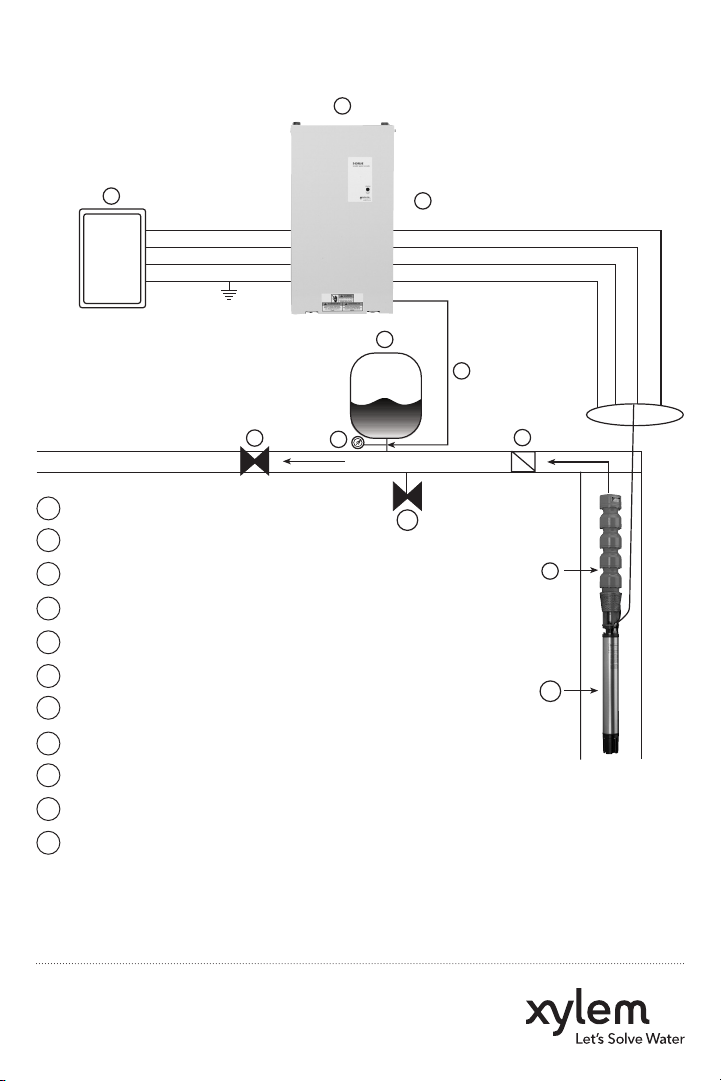
S-Drive Typical Installation
1
2
SUPPLY POWER
L1
L2
L3
GND
8
3
1 S-Drive Controller
2 Fusible Disconnect
3 Pressure Gauge
4 Air Diaphragm Tank
5 Pressure Transducer
6 3 Phase Output (Always)
7 Discharge Check Valve
8 Gate Valve (Highly Recommended)
9 Submersible Pump End
10 Submersible Motor (3 Phase)
11 Pressure Relief Valve
6
T1
T2
T3
GND
4
5
7
FLOW
11
9
10
NOTE: for single phase input, connect L1 and L3, then set motor overload switches to
50% of controller rating or lower.
Xylem Inc.
www.xyleminc.com
© 2011 Xylem Inc. IMS-SDQ-1 December 2011
Page 3

QUICK START GUIDE
IMS-SDQ-2
S-Drive Quick Start Up Guide
Refer to the status code label on the side of the controller access cover
to diagnose system errors. See the following diagram.
Red Flashes Fault Code Restart Action
Constant Replace Controller Controller will not restart. Power must be reset to
clear the fault.
2 Blinks No Water/Loss of Prime Controller will restart automatically according to
No Water Restart Time the switches (switches 3 and 4 of bank 2).
3 Blinks Sensor Fault Controller will restart automatically when the sensor
signal is within the valid operating range.
4 Blinks Pump or Motor Bound Controller will restart automatically 5 times. After 5
faults the power must be reset to clear the fault.
5 Blinks Short Circuit/ Controller will not restart. Power must be reset to
Ground Fault clear the fault.
6 Blinks Input Phase Loss Controller will restart automatically 5 times. After 5
faults the power must be reset to clear the fault.
7 Blinks Temperature Controller will restart automatically when tempera
ture is within the operating range of the controller.
8 Blinks Over Voltage Controller will restart automatically when the input
voltage is within the operating range of the controller.
9 Blinks Motor Overload Controller will restart automatically.
Page 4

S-Drive Motor Overload Settings
Motor Overload Setting
Supply Frame Model
Voltage Size Number
SPD20050F
SPD20075
SPD20100
SPD20100F
208/230
SPD20200
SPD20200F
SPD20250
SPD20300
SPD20300F
SPD40050
SPD40075
SPD40075F
SPD40100
SPD40100F
460
SPD40150F
SPD40200
SPD40200F
SPD40250
SPD40300
SPD40300F
* Only use 50% and 40% settings for 1Ø input
SPD20050
1
SPD20075F
2
SPD20150
SPD20150F
3
SPD20250F
4
SPD40050F
1
SPD40150
2
SPD40250F
3
100% 95% 90% 85% 80% 70% 50%* 40%
17.8 16.9 16.0 15.1 14.2 12.5 8.9 7.1
26.4 25.1 23.8 22.4 21.1 18.5 13.2 10.6
37.0 35.2 33.3 31.5 29.6 25.9 18.5 14.8
47.4 45.0 42.7 40.3 37.9 33.2 23.7 19.0
60.6 57.6 54.5 51.5 48.5 42.4 30.3 24.2
76.0 72.2 68.4 64.6 60.8 53.2 38.0 30.4
94.0 89.3 84.6 79.9 75.2 65.8 47.0 37.6
8.9 8.5 8.0 7.6 7.1 6.2 4.5 3.6
13.2 12.5 11.9 11.2 10.6 9.2 6.6 5.3
18.5 17.6 16.7 15.7 14.8 13.0 9.3 7.4
23.7 22.5 21.3 20.1 19.0 16.6 11.9 9.5
30.3 28.8 27.3 25.8 24.2 21.2 15.2 12.1
37.5 35.6 33.8 31.9 30.0 26.3 18.8 15.0
47.0 44.7 42.3 40.0 37.6 32.9 23.5 18.8
*
Xylem Inc.
www.xyleminc.com
© 2011 Xylem Inc. IMS-SDQ-2 December 2011
 Loading...