

Page 1

QUICK START GUIDE
IMS-ABII-1
Aquavar ABII Quick Start Guide
Installation Steps:
1. Install the Pump
• Plumb suction and discharge of pump into piping.
• Install a check valve on the suction side.
• Locate the pump as near liquid source as possible.
2. Install the Pressure Transducer
• Install the pressure transducer in the tank tee provided with the unit.
• Locate the transducer within 120” of the controller.
3. Mount the Controller
• Mount vertically in a well ventilated, shaded area with 8 inches of free air
space on every side and temperature between 34º F and 104º F.
4. Connect Input Power
• Connect the 1Ø power from a 20 amp 2-pole circuit breaker.
• Do not use GFCI protection with ABII as nuisance tripping will result.
5. Output Power Connections
• Connect the output power leads from the controller to the 3 motor leads
in the conduit box on the motor.
6. Set the motor Overload Switches (or dials, 3 and 5 HP)
• Complete systems have overloads pre-set at factory.
7. Set the Pressure - Factory pre-set is 50 PSI
• Push and Hold the Increase or Decrease Pressure Adjust Pushbutton
until the desired pressure setting is reached.
• The maximum allowable pressure setting is 85 psi.
8. Set the Application Switches (or dials, 3 and 5 HP)
• Minimum Speed of 10 Hz – the incoming pressure is within 20 PSI of the
desired pressure setting.
• Minimum Speed of 30 Hz – the incoming pressure is 20 PSI or more below
the desired pressure, if pumping from a tank or if drawing a suction lift.
• Ramp Speed – Slow - Low ow; Medium - Medium ow; Fast - High ow
Page 2
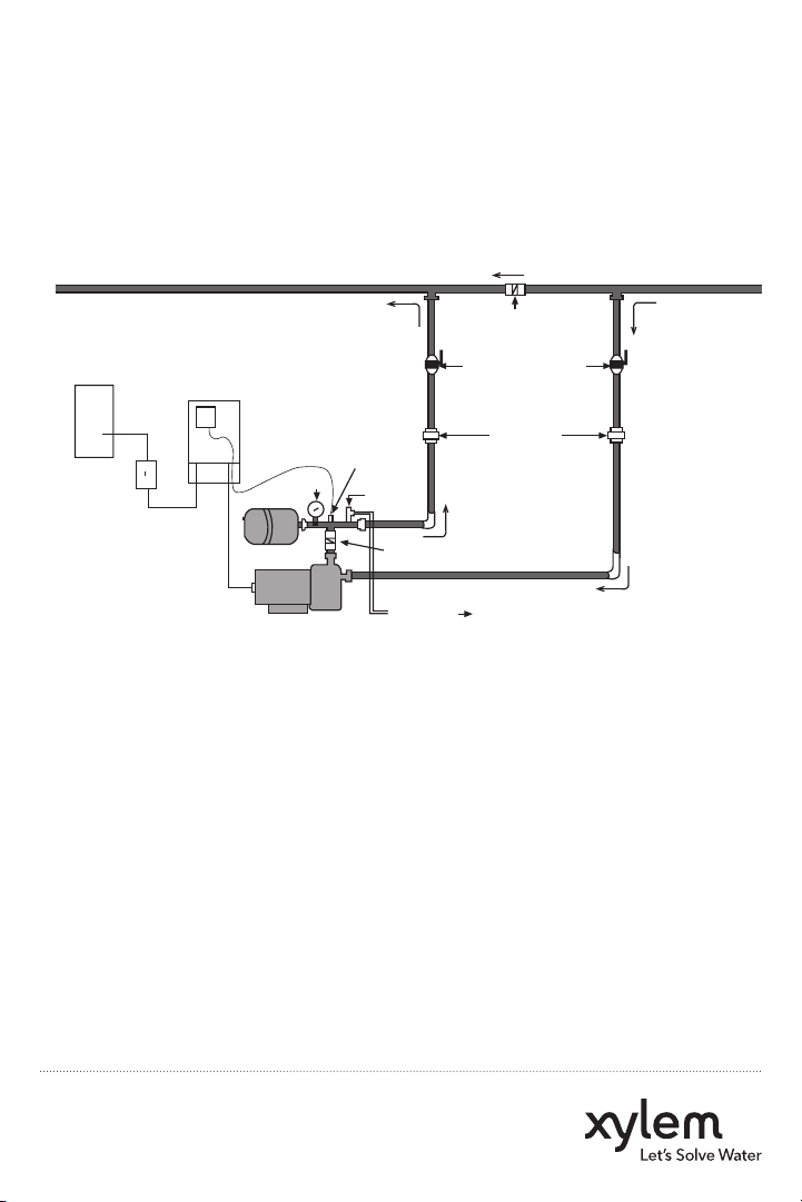
Aquavar ABII Controller
Typical Installation
This diagram shows a set-up for municipal water connection. This allows pump
maintenance without main line shut-off.
Home Supply Water Main
Check Valve
Isolation Valves
Unions
Disconnect
Circuit
Breaker
AquaBoost
Controller
Transducer
Gauge
Tank
Motor/Pump
Relief
Valve
Check Valve
To Drain
AquaBoost II Required Components:
1. Pump with Motor
2. AquaBoost II Controller with Integral Pressure Sensor Cable
3. Pressure Tank
4. Pressure Sensor
5. Mounting Kit
6. Tank Tee with Pipe Plug
7. Pressure Gauge
Xylem Inc.
www.xyleminc.com
© 2011 Xylem Inc. IMS-ABII-1 December 2011
Page 3

QUICK START GUIDE
Aquavar ABII
Quick Start Up Guide
LABELS FOUND ON THE CONTROLLER ACCESS COVER:
Fault Codes
IMS-ABII-2
Motor Overload Setting
WARNING: Disconnect Power And Wait For LED Indicator To
Turn Off Before Touching Motor Overload Setting Switches.
1 = UP 0 = DOWN
DIP Switch Setting Motor Overload Setting (Amps)
1 2 3 4 1AB2 2AB2
1 1 1 1 2.5 4.6
1 1 1 0 2.8 5.2
1 1 0 1 3.3 5.3
1 0 1 1 3.5 5.8
0 1 1 1 3.8 6.5
0 0 0 0 4.2 6.9
Motor Overload Setting Label
Use this label to choose the correct Motor Overload Switch
Setting. This label is found under the controller access cover.
Status Code Label
Use this label to diagnose any system errors. This label is
found on the side of the controller access cover.
Application Switch Setting
WARNING: Disconnect Power And Wait For LED Indicator To Turn
Off Before Touching Application Setting Switches.
DIP Switch Setting 1 = UP 0 = DOWN
1 2 3 4 Minimum Speed (Hz) Ramp Setting
1 1 1 1 * 10 Slow
1 1 1 0 * 10 Medium
1 1 0 1 * 10 Fast
1 0 1 1 30 Slow
0 1 1 1 30 Medium
0 0 0 0 30 Fast
*THESE SETTINGS ARE NOT TO BE USED WITH SUBMERSIBLE PUMPS.
Constant Standby/Low Voltage
Blinking Pump Running
Constant Replace Controller
1 Blink No Water/Loss Of Prime
2 Blinks Tank Water-Logged
3 Blinks Pressure Sensor Fault
4 Blinks Pump or Motor Bound
5 Blinks Short Circuit
6 Blinks Ground Fault
7 Blinks High Temperature
8 Blinks Over Voltage (>264V)
9 Blinks Motor Overload
Status Codes*
Green Light Codes
Red Light Codes
*No Light - No/Very Low Voltage
Application
Switch
Setting
Label
Use this label
to choose
the correct
Application
Switch Setting.
This label is
found under
the controller
access cover.
Page 4

Aquavar ABII Wiring Diagram
1 AND 2 HP
Input (Wht)
Com. (Blk)
+5V (Red)
WHITE
RED
BLACK
Input
230V
1 Phase
GNDL1L2 (N)
GREEN
BLACK
BLACK
See Manual For
Switch Settings
Motor
Applic.
Overload
Type
Setting
1 2 3 4 1 2 3 4
Output
To Motor
T1T2T3
BLUE
RED
BLACK
GND
GREEN
Pressure
Transducer
Line input power from
2-pole disconnect or
circuit breaker.
Line output to motor.
Correct motor rotation
determines order of colors.
Note: Verify controller voltage input on label. 115 volt or 230 volt.
3 AND 5 HP
* Input Power Supply
Single Phase
208-240 VAC
GROUND
Note: Use 2 pole disconnect
or circuit breaker.
Xylem Inc.
www.xyleminc.com
© 2011 Xylem Inc. IMS-ABII-2 December 2011
INPUT BLOCK
L1 L2 GND GND RED BLK YEL
GROUND
OUTPUT BLOCK
230 VOLT
THREE PHASE
MOTOR
THREE PHASE
MOTOR
OUTPUT
Pressure
Transducer
 Loading...