

Page 1
INSTRUCTION MANUAL
IM256R00
SPS83
PRIME LINE® SUCTION STRAINER
INSTALLATION, OPERATION AND MAINTENANCE INSTRUCTIONS
Page 2
DANGER
WARNING
CAUTION
TABLE OF CONTENTS
SAFETY INSTRUCTIONS
SUBJECT PAGE
Unboxing and Inspection ...............................................3
Piping and Testing ........................................................... 3
Operation..........................................................................3
Repair Parts ....................................................................... 4
OWNER’S INFORMATION
Please ll in data.
Model Number: SPS83
Dealer:
Dealer Telephone:
Purchase Date:
Installation Date:
TO AVOID SERIOUS OR FATAL PERSONAL INJURY
OR MAJOR PROPERTY DAMAGE, READ AND
FOLLOW ALL SAFETY INSTRUCTIONS IN THE
MANUAL AND ON THE PUMP.
This is a SAFETY ALERT SYMBOL.
When you see this symbol on the
pump or in the manual, look for one
of the following signal words and
be alert to the potential for personal
injury or property damage.
Warns of hazards that WILL cause
serious personal injury, death or
major property damage.
Warns of hazards that CAN cause
serious personal injury, death or
major property damage.
Warns of hazards that CAN cause
personal injury or property damage.
NOTICE: INDICATES SPECIAL INSTRUCTIONS
WHICH ARE VERY IMPORTANT AND
MUST BE FOLLOWED.
THIS MANUAL IS INTENDED TO ASSIST IN THE
INSTALLATION AND OPERATION OF THIS UNIT
AND MUST BE KEPT WITH THE UNIT.
THOROUGHLY REVIEW ALL INSTRUCTIONS
AND WARNINGS PRIOR TO PERFORMING ANY
WORK ON THIS PUMP.
MAINTAIN ALL SAFETY DECALS.
WARNING
UNIT NOT DESIGNED FOR USE
WITH HAZARDOUS LIQUIDS OR
FLAMMABLE GAS.
Hazardous fluids
can cause fire,
burns or death.
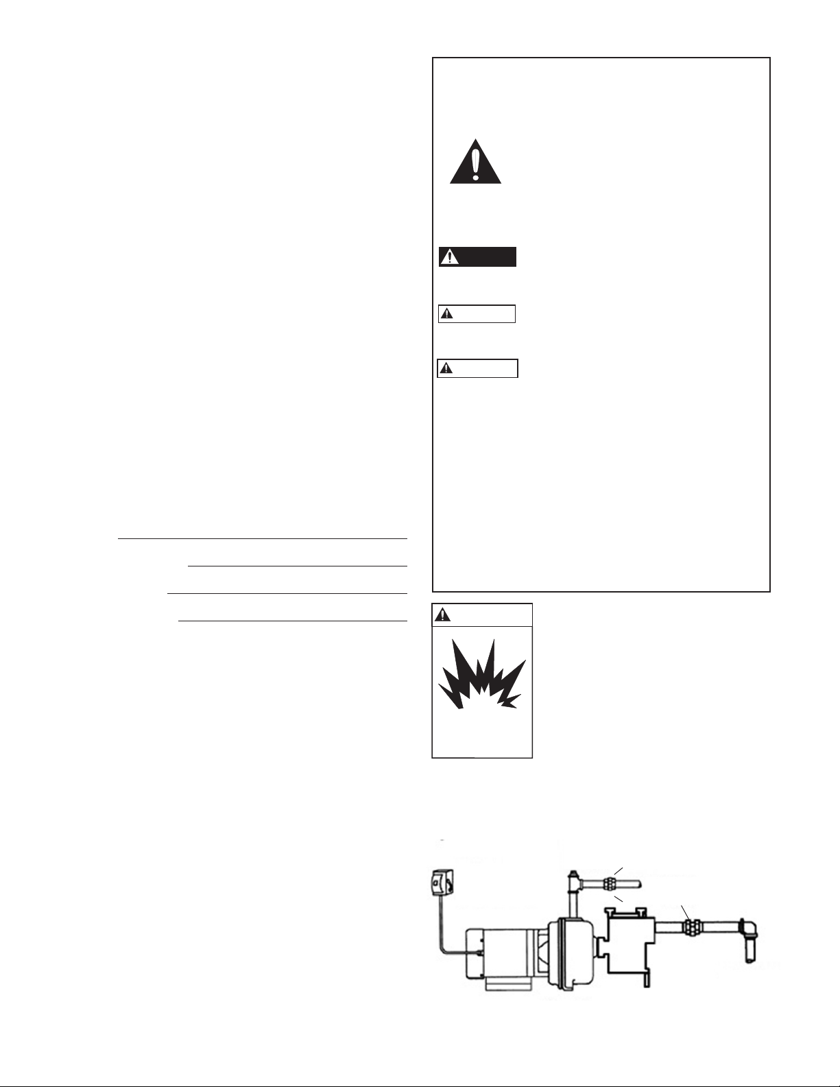
EXAMPLE PIPING LAYOUT
FUSED OR
CIRCUIT BREAKER
DISCONNECT
MEANS
PRIMING
OPENING
UNION
DISCHARGE
UNION
SUCTION
Figure 1
2
Page 3

UNBOXING AND INSPECTION
WARNING
WARNING
STRAINER TESTING AND OPERATION
Unbox and handle with care.
Inspect unit for damage and report all damage to
carrier immediately.
Hazardous suction. Can trap hair or body
parts, causing severe injury or death.
Do not block suction.
INSTALLATION
PIPING - GENERAL
• Piping MUST be installed horizontally on a solid at
surface, with discharge on top.
• Allow adequate space for servicing and ventilation
with strainer. Protect unit from weather and water
damage due to rain or ooding or freezing
temperatures.
• Piping should be no smaller than the suction and
discharge connections and kept as short as possible,
avoiding unnecessary ttings to minimize friction
losses.
• All piping MUST be independently supported and
MUST NOT place any piping loads on the pump.
• Use hex nut and bolt (Repair parts # 5 & 6) to level
strainer with pump suction during installation. DO
NOT cantilever strainer off pump suction – use hex
nut and bolt to prevent unnecessary strain on pump
suction.
NOTICE: DO NOT FORCE PIPING INTO PLACE AT
PUMP SUCTION AND DISCHARGE CONNECTIONS.
• The use of Teon™ tape, or equivalent, is
recommended for ALL piping joints.
• All pipe joints MUST be airtight.
• Total suction lift, including elevation and pipe friction
losses should not exceed 25 feet.
• For lifts longer than 10 feet, a foot valve or check
valve must be used in the suction piping.
Before removing strainer cover:
1. SHUT OFF pump before starting
2. CLOSE ALL VALVES in suction and discharge
piping.
3. RELEASE ALL PRESSURE from pump and piping
system
4. Hydrotest pump and strainer assembly to ensure
strainer was installed and attached to pump
correctly.
MAXIMUM HYDROSTATIC TEST
PRESSURE IS 20 PSI WATER PRESSURE
After hydrostatic pressure test, release all
pressure in the system before removing
strainer cover.
• To avoid damaging the pump or putting
unnecessary strain on the pump and/or strainer/
support pipe independently of the pump/strainer.
• Center the cover on the strainer body when
installing.
• When installing the cover, clean O-Ring groove in
strainer body and lubricate the following surfaces
with petroleum jelly.
1. O-ring
2. Sealing surfaces of the strainer cover and body
3. Threads and faces of wing nuts
• Lubricating these surfaces will prevent corrosion,
provide a better seal, and improve ease of
maintenance.
• Hand tighten lock handles, alternating back and
forth between handles to ensure even compression;
hand tighten only.
• Use a wrench on the handle ats if necessary to
remove cover.
NOTICE: A clogged suction strainer will impact
performance and eventually cause cavitation. Clean
and empty strainer basket on a regular schedule to
prevent clogging.
3
Page 4

REPAIR PARTS
1
Key No. Part Description Part No.
1 T- Handle 6K214
2 Lid O-ring 5K526
2
3 Strainer Basket 15K106
4
Pipe Plug ¼”
6K2
5 Hex Nut 3/8-16 13K89
6 Cap Screw 3/8-16 x 2 13K450
7 Suction Gasket 5K527
3
7
4
5
6
GOULDS WATER TECHNOLOGY LIMITED WARRANTY
This warranty applies to all water systems pumps manufactured by Goulds Water Technology.
Any part or parts found to be defective within the warranty period shall be replaced at no charge to the dealer during the warranty period. The warranty period shall exist for a
period of twelve (12) months from date of installation or eighteen (18) months from date of manufacture, whichever period is shorter.
A dealer who believes that a warranty claim exists must contact the authorized Goulds Water Technology distributor from whom the pump was purchased and furnish complete
details regarding the claim. The distributor is authorized to adjust any warranty claims utilizing the Goulds Water Technology Customer Service Department.
The warranty excludes:
(a) Labor, transportation and related costs incurred by the dealer;
(b) Reinstallation costs of repaired equipment;
(c) Reinstallation costs of replacement equipment;
(d) Consequential damages of any kind; and,
(e) Reimbursement for loss caused by interruption of service.
For purposes of this warranty, the following terms have these definitions:
(1) “Distributor” means any individual, partnership, corporation, association, or other legal relationship that stands between Goulds Water Technology and the dealer in purchases,
consignments or contracts for sale of the subject pumps.
(2) “Dealer” means any individual, partnership, corporation, association, or other legal relationship which engages in the business of selling or leasing pumps to customers.
(3) “Customer” means any entity who buys or leases the subject pumps from a dealer. The “customer” may mean an individual, partnership, corporation, limited liability company,
association or other legal entity which may engage in any type of business.
THIS WARRANTY EXTENDS TO THE DEALER ONLY.
Xylem Inc.
2881 East Bayard Street Ext., Suite A
Seneca Falls, NY 13148
Phone: (800) 453-6777 • Fax: (888) 322-5877
www.gouldswatertechnology.com
Goulds is a registered trademark of Goulds Pumps, Inc. and is used under license.
© 2014 Xylem Inc. IM256 Rev. 0 January 2014
 Loading...