

Page 1

INSTRUCTION MANUAL
IM070
Models 1GA/2GA
INSTALLATION, OPERATION AND MAINTENANCE INSTRUCTIONS
Page 2

2 1GA/2GA Installation, Operation and Maintenance Manual
Page 3

Table of Contents
Table of Contents
Introduction and Safety ........................................................................................................................2
Data Plate Interpretation ......................................................................................................................7
Product Description .............................................................................................................................. 8
General Design of a 1GA/2GA Pump .................................................................................................... 9
Installation ..........................................................................................................................................11
Electrical Connections ........................................................................................................................13
Cable Chart ........................................................................................................................................15
Transportation and Storage .................................................................................................................16
Operation ........................................................................................................................................... 17
Care and Maintenance ........................................................................................................................ 18
Oil Change .........................................................................................................................................19
Service Log ......................................................................................................................................... 21
Warranty .............................................................................................................................................24
Owners Information
Complete this information for your records.
Model number and serial number may be found
on the tag mounted to the motor adapter.
Model Number
Serial Number
___________________________________
Dealer
Dealer phone number
Date of purchase
Date of installation
1GA/2GA Installation, Operation and Maintenance Manual 1
___________________________
____________________________
______________________
__________________________
________________________
Page 4

Introduction and Safety
I. Introduction and Safety
Introduction
Description
This manual provides instructions for the Installation, Operation and Maintenance of the
Goulds 1GA/2GA pumps.
Requirement
This manual must be read and understood before installation and start-up. Goulds shall not
be liable for physical injury, damage or delays caused by a failure to observe the instructions
for installation, operation and maintenance contained in this manual.
Content
This instruction manual covers several different pump models that all have similar power
end configurations. Most assembly, disassembly and inspection procedures are the same for
all the pumps. However, where there are differences, they are called out separately within
the manual. The design, materials and workmanship incorporated in the construction of
Goulds Water Technology makes them capable of giving long, trouble free service. The
life and satisfactory service of any mechanical unit, however, is enhanced and extended
by correct application, proper installation, periodic inspection, condition monitoring
and careful maintenance. This instruction manual was prepared to assist operators in
understanding the construction and the correct methods of installing, operating and
maintaining these pumps.
Key Topics
Data Plate Interpretation
Product Description
General Design
Installation
Electrical Connections
Cable Chart
Transportation and Storage
Operation
Care and Maintenance
Oil Change
2 1GA/2GA Installation, Operation and Maintenance Manual
Page 5
Safety
It is extremely important that you read, understand, and follow the safety messages and
regulations carefully before handling a Goulds Water Technology product. They are published to help prevent
• personal accidents and health problems
• damage to the product
• product malfunction
Observe all safety messages highlighted in other sections of this manual.
A pump is a pressure-containing device with rotating parts that can be dangerous.
Caution: You must observe the instructions for installation, operation, and maintenance contained in this manual. Failure to do so could result in physical injury,
damage, or delays.
Safety message levels
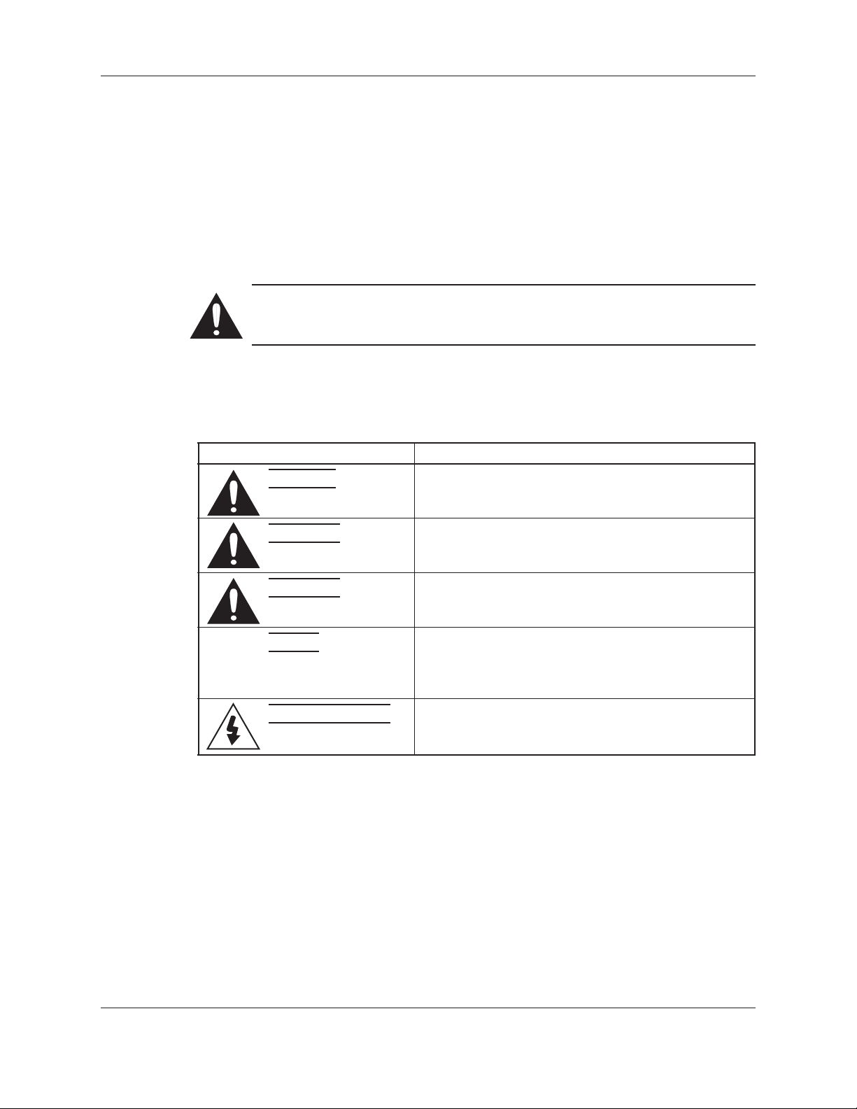
Table 1: Definitions
Safety message level Indication
Introduction and Safety (continued)
Danger: Indicates a hazardous situation which, if not
avoided, will result in death or serious injury.
Warning: Indicates a hazardous situation which, if not
avoided, could result in death or serious injury.
Caution: Indicates a hazardous situation which, if not
avoided, could result in minor or moderate injury.
Note: Indicates a potential situation which, if not avoided,
may result in undesirable results or state. Indicates a
practice not related to personal injury.
Electrical Hazard: Indicates the possibility of electrical risks if
direction are not applied in a proper manner.
Environmental safety
Preventive measures for the working area
Always keep the pump station clean to avoid and/or discover emissions.
Recycling guidelines
Always recycle according to the guidelines listed below:
1. Follow local laws and regulations regarding recycling if the unit or parts are accepted by
an authorized recycling company.
2. If the first guideline is not applicable then return the unit or parts to the nearest Goulds
Water Technology representative.
1GA/2GA Installation, Operation and Maintenance Manual 3
Page 6

Introduction and Safety (continued)
Waste and emissions
Observe these safety regulations regarding waste and emissions:
• Dispose appropriately of all waste.
• Handle and dispose of the pumpage in compliance with applicable environmental
regulations.
• Clean-up all spills in accordance with safety and environmental procedures.
• Report all environmental emissions to the appropriate authorities.
Reference for electrical installation
For electrical installation recycling requirements, consult your local electric utility.
User health and safety
Safety equipment
Use safety equipment according to the company regulations. The following safety
equipment should be used within the working area depending on the fluid being pumped:
• helmet
• safety goggles (with side shields)
• protective shoes
• protective gloves
• gas mask
• hearing protection
Note: The noise level of the product is lower than 70 dB. However, the
noise level of 70 dB may be exceeded in some installations and at certain
operating points on the performance curve. Make sure that you understand
the noise level requirements in the environment where the pump is
installed. Failure to do so may result in hearing loss or violation of local
laws.
The working area
Observe these regulations and warnings in the working area:
• Always keep the work area clean.
• Pay attention to the chemical and physical characteristics of the gas and vapors present
in hazardous areas.
• Avoid all electrical dangers. Pay attention to the risks of electric shock or arc ash
hazards.
Product and product positioning requirements
Observe these requirements for the product and the product positioning:
• Never operate a pump unless safety devices are installed.
• Three-phase motors must have a properly sized starter with properly sized heaters
to provide overload and under voltage protection. Single-phase motors have built-in
overload protectors.
• Never start a pump without the proper priming.
• Never run a pump below the minimum rated ow or with any suction or discharge
valve closed.
Electrical connections
Electrical connections must be made by authorized electricians in compliance with all
international, national, state and local rules.
4 1GA/2GA Installation, Operation and Maintenance Manual
Page 7
Observe the following regulations and warnings for electrical connections.
• Make sure that the product is isolated from the power supply and can not be
energized by mistake. This rule applies to the control circuit as well.
• Make sure that the thermal contacts are connected to a protection circuit according
to the product approvals, and that they are in use.
Observe the following regulations for grounding connections.
Table 2: Grounding
Grounding regulation Comment
All electric equipment must be grounded. This rule applies to pumps and mixers as
well as monitoring equipment.
Precautions before work
Observe the following safety precautions before working with or in connection with the
product:
• Make sure that there are no poisonous gases within the work area.
• Provide a suitable barrier around the work area, for example a guard rail.
• Make sure that all safety guards are in place and secure.
• Make sure that the equipment is properly insulated when operating at extreme
temperatures.
• Allow all system and pump components to cool before you handle them.
• Make sure that you have a clear path of retreat.
• Make sure that the product cannot roll or fall over and injure people or damage
property.
• Make sure that the lifting equipment is in good condition.
• Use a lifting harness, a safety line, and a breathing device as required.
• Make sure that the product has been thoroughly cleaned.
• Make sure that a rst-aid kit is close at hand.
• Check the explosion risk before welding or using electric hand tools.
Introduction and Safety (continued)
Precautions during work
Observe the following safety precautions when working with or in connection with the
product:
• Never work alone.
• Stay clear of suspended loads.
• Always lift the product by its lifting device.
• Beware of the risk of a sudden start if the product is used with an automatic level
control.
• Beware of the starting jerk, which can be powerful.
• Rinse the components in water after disassembling the pump.
• Do not exceed the maximum working pressure of the pump.
• Do not open any vent or drain valves or remove any plugs while the system is
pressurized. Ensure that the pump is isolated from the system and that pressure is
relieved before you disassemble the pump, remove plugs, or disconnect piping.
1GA/2GA Installation, Operation and Maintenance Manual 5
Page 8

Introduction and Safety (continued)
• Always bear in mind the risk of:
• electrical accidents
• burn injuries
Clean chemicals from the eyes
1. Forcibly hold the eyelids apart with the fingers.
2. Rinse the eyes for at least 15 minutes. Use an eyewash or running water.
3. Seek medical attention.
Clean chemicals from the body
1. Remove contaminated clothing.
2. Wash the skin with soap and water for at least 1 minute.
3. If required, seek medical attention.
Product approval standards
Regular standards
All electrical ratings and performance of the motors comply with UL, CSA and NEMA
standards.
Product warranty
Personnel requirements
All work on the product must be carried out by certified electricians and Goulds Water
Technology authorized service centers.
Goulds Water Technology disclaims all responsibility for work done by untrained and
unauthorized personnel.
Modification and spare parts
Modifications or changes to the product/installation should only be carried out after
consulting with Goulds Water Technology. Original spare parts and accessories authorized
by Goulds Water Technology are essential for compliance. The use of other parts can
invalidate any claims for warranty or compensation and explosion-proof approvals.
Warranty claim
For warranty claim, contact your Goulds Water Technology representative.
6 1GA/2GA Installation, Operation and Maintenance Manual
Page 9

II. Data Plate Interpretation
Data Plate Interpretation
General Data Plate
A
B
H
mm
N
M
Y
T/X
R/U
S/V
C
cos �
W
v
IEC 34-1 1969 cl.F
E
A
Q
Hz
%
r/min
kg
J
F
K
L
D
A Internal L Operating duty, cont./int.
B Serial number M Impeller/propeller diameter
C Shaft power N Factory code
D Rated speed Q Temperature class
E Product number R/U Rated voltage
F Weight S/V Rated current
H Curve code, first digit = number of poles T/X Stator connection
J Number of phases, type of current, frequency W Special order number
K Power factor Y Motor number
Approval Plate
This approval plate applies to an explosion-proof submersible Goulds pump. The plate is
used together with the general data plate on the pump.
FM: Factory Mutual
Class I, Division I, Group C and D
Class II and III, Division I, Group E, F and G
Maximum Operating Temperature T4
Explosion Proof for use in
FM
APPROVED
Class I, Division 1, Group C and D
Dust Ignition Proof for use in
Class II, Division 1, Group E, F and G
Suitable for use in Class III, Division 1
Hazardous Locations
104º F (40º C) Ambient Limits
CAUTION: DEENERGIZE PUMP BEFORE OPENING
1GA/2GA Installation, Operation and Maintenance Manual 7
Page 10

Product Description
III. Product Description
Introduction
Thank you for buying a submersible Goulds pump. In this Installation, Care and
Maintenance manual, you will find general information on how to install and service the
1GA or 2GA pump to give it a long and reliable life. In the Parts List you will find all the
specific technical data for your pump.
Application
This Installation, Care and Maintenance manual applies to a submersible Goulds 1GA or
2GA pump. If you have bought an explosion proof pump (please see approval plate on your
pump or Parts List) special handling instructions apply as described in this document.
The pump is intended to be used for pumping of sewage for high head application.
The pumps must not be used in highly corrosive liquids. See pH limits below.
The pump is available for permanent installation in a sump or portable installation.
For further information on applications, contact your nearest Goulds wastewater
representative.
Specific Technical Data
For specific technical data regarding your pump, please see Parts List.
General Technical Data
Liquid Temperature: Maximum 104º F (40º C). The pump can be operated at full load only
if fully submerged.
Liquid Density: Maximum 9.2 lb per US gallon (1100 kg/m3)
The pH of the Pumped Liquid: 6-13 (cast iron pumps)
Depth of Immersion: Maximum 65 ft (20 m)
Warranty Claim
The pumps are high quality products with expected reliable operation and long life.
However, should the need arise for a warranty claim, please contact your Goulds
representative.
In some installations and at certain operating points on the performance curve,
the noise level of 70 dB or the noise level specified for the actual pump may be
exceeded.
Only ex-approved pumps may be used in an explosive or flammable
environment.
8 1GA/2GA Installation, Operation and Maintenance Manual
Page 11

General Design of a 1GA/2GA Pump
IV. General Design of a 1GA/2GA Pump
Design
The pump is a submersible, electric motor-driven product.
1. Impeller
The impeller has a cutter mounted at the inlet which grinds solids.
2. Shaft Seals
The pump has two mechanical face seals - one inner and one outer, with an intermediate
oil housing.
3. Shaft
The shaft is delivered with the rotor as an integral part. Shaft material: stainless steel.
4. Bearings
The support bearing of the rotor consists of a single-row ball bearing. The main bearing
of the rotor consists of a two-row angular contact ball bearing.
5. Oil Housing
The oil lubricates and cools the seals and acts as a buffer between the pump housing and
the electric motor.
6. Motor
Squirrel-cage 1-phase or 3-phase induction motor.
The motor can be started by direct on-line or star-delta starting.
The motor can be run continuously or intermittently with a maximum of 15 evenly
spaced starts per hour.
1GA/2GA Installation, Operation and Maintenance Manual 9
Page 12

General Design of a 1GA/2GA Pump (continued)
The motors are tested in accordance with IEC 34-1, 1969.
The stator is insulated in accordance with class F (310º F, 155º C). The motor is designed
to deliver its rated output at ± 5% variation from the rated voltage. Without overheating
the motor, ± 10% variation from the rated voltage can be accepted provided that the
motor does not run continuously at full load. The motor is designed to operate at a
voltage imbalance of up to 2% between the phases.
Monitoring Equipment
The stator incorporates thermal contacts connected in series.
The pump can be equipped with sensors for sensing water in the stator housing.
10 1GA/2GA Installation, Operation and Maintenance Manual
Page 13
V. Installation
Handling Equipment
Lifting equipment is required for handling the pump.
Stay clear of suspended loads.
Always lift the pump by its lifting handle, never by the motor cable or the hose.
The minimum height between the lifting hook and the floor shall be sufficient to lift the
pump out of the sump.
The lifting equipment shall be able to hoist the pump straight up and down in the sump,
preferable without the need for resetting the lifting hook.
Oversize lifting equipment could cause damage if the pump should stick when being lifted.
Make sure that the lifting equipment is securely anchored.
General Recommendations
To ensure proper installation, please see the dimensions on the dimensional drawing in the
Parts List.
Installation
NOTE: The end of the cable must not be submerged. It must be above flood level, as water
may penetrate through the cable into the junction box or the motor.
Check that the lifting handle and chain are in good condition.
For automatic operation of the pump (level control), it is recommended that the level
regulators be used at low voltage. The data sheet delivered with the regulators gives the
permissible voltage. Local rules may specify otherwise.
Clean out all debris from the sump before the pump is lowered down and the station is
started.
Safety Precautions
In order to minimize the risk of accidents in connection with the service and installation
work, the following rules should be followed:
1. Never work alone. Use a lifting harness, safety line and a respirator as required. Do not
2. Make sure there are no poisonous gases within the work area.
Special rules apply to installation in explosive atmosphere. Intrinsically safe
circuits are normally required (Ex I) for the automatic level control system by
level regulators.
ignore the risk of drowning!
3. Check the explosion risk before welding if using electric hand tools.
4. Do not ignore health hazards. Observe strict cleanliness.
5. Bear in mind the risk of electrical accidents.
6. Make sure that the lifting equipment is in good condition.
1GA/2GA Installation, Operation and Maintenance Manual 11
Page 14

Installation (continued)
7. Provide a suitable barrier around the work area, e.g. a guard rail.
8. Make sure you have a clear path of retreat!
9. Use safety helmet, safety goggles and protective shoes.
10. All personnel who work with sewage systems must be vaccinated against diseases to
11. A first-aid kit must be close at hand.
12. Note that special rules apply to installation in explosive atmosphere.
Follow all other health and safety rules and local codes and ordinances.
which they may be exposed.
12 1GA/2GA Installation, Operation and Maintenance Manual
Page 15

VI. Electrical Connections
Before starting work on the pump, make sure that the pump and the control
panel are isolated from the power supply and cannot be energized.
If the pump is equipped with automatic level control, there is a risk of sudden
restart.
All electrical equipment must be earthed. This applies to both pump equipment
and any monitoring equipment. Failure to heed this warning may cause a lethal
accident. Make sure that the earth lead is correctly connected by testing it.
If persons are likely to come into physical contact with the pump or pumped
media (liquid), e.g. on construction sites and farms, the earthed (grounded)
socket must have an additional earth-(ground-) fault protection device (GFI)
connected.
When pumping near a lake (jetties, beaches, ponds, fountains, etc.) a safetydistance of at least 65 feet (20 m) between the person and the pump is
applicable.
The pump must never be placed directly into a swimming pool. If used in
connection with swimming pools, special safety regulations apply.
Electrical Connections
NOTE FOR EX-VERSION: Electrical connections on the explosion-proof motor
must be made by authorized personnel. Goulds Water Technology disclaims all
responsibility for work done by untrained, unauthorized personnel.
The pump may be used only in accordance with the approved motor data stated
on the pump’s plates.
Thermal contacts must be connected to protection circuit intended for that
purpose according to the approval of the product.
All electrical work shall be carried out under the super-vision of an authorized electrician.
Local codes and regulations shall be complied with.
Check on the data plate which voltage supply is valid for your pump.
Check that the main voltage and frequency agree with the specifications on the pump data
plate.
If the pump can be connected to different voltages, the connected voltage is specified by a
yellow sticker.
Connect the motor cable to the starter equipment as illustrated in the wiring diagrams.
Conductors that are not in use must be isolated.
The cable should be replaced if the outer sheath is damaged. Contact a Goulds service shop.
Make sure that the cable does not have any sharp bends and is not pinched.
Under no circumstances may the starter equipment be installed in the sump.
1GA/2GA Installation, Operation and Maintenance Manual 13
Page 16

Electrical Connections (continued)
NOTE: For safety reasons, the earth conductor should be approximately 2.0” (50 mm)
longer than the phase conductors. If the motor cable is jerked loose by mistake, the earth
conductor should be the last conductor to come loose from its terminal. This applies to both
ends of the cable.
Thermal contacts are incorporated in the stator. The thermal contacts can be connected to
maximum 250 V, breaking current maximum 4 A. Goulds Water Technology recommends
that they be connected to 24 V over separate fuses to protect the other automatic
equipment.
Make sure that the pump is correctly earthed (grounded).
When using a variable-frequency-drive (VFD) special rules have to be followed to avoid
clogging and over-heating. Contact your VFD supplier and ask for electrical limitations.
Remember that the starting current in direct online starting can be up to six times higher
than the rated current. Make sure that the fuses or circuit breakers are of the proper rating.
The Parts List gives rated current. Fuse rating and cable shall be selected in accordance with
local rules and regulations. Note that with long cables, the voltage drop in the cable must be
taken into consideration, since the motor’s rated voltage is the voltage that is measured at
the terminal board in the pump.
The overload protection (motor protection breaker) for direct online starting shall be set to
the motor rated current as given on the data plate.
Check the phase sequence in the mains with the phase sequence indicator.
If intermittent operation is prescribed (see Data Plate), the pump shall be provided with
control equipment that provides such operation.
Single Phase Operation
The single phase pumps must be equipped with a starter which has start and run capacitors.
A special designed starter is required for the operation of single phase pumps. The
connection of the motor cable to the starter is shown in the wiring diagram.
NOTE: It is not possible to change the direction of rotation of a single phase pump by
changing the cable conductors on the starter. Please contact your nearest Goulds Water
Technology representative.
Monitoring Equipment
The FLS sensor consists of a small float switch for sensing water in the stator housing. Its
design makes it suitable for pumps in vertical installations. The FLS sensor is installed in the
bottom of the stator housing.
The MiniCas II is a monitoring relay to which FLS is connected.
Check:
• signals and tripping function.
• that relays, lamps, fuses and connections are intact.
Replace defective equipment.
14 1GA/2GA Installation, Operation and Maintenance Manual
Page 17
VII. Cable Chart
Cable Chart
3-Phase, Direct Online Starting
3~
GC
L1 L2 L3 T1 T2
Single Phase
GC
SUBCAB
GC
GC
L1 L2 L3
Connection
Conductors Starter
T2
T1
Connection
Conductors Starter
123
SUBCAB
1
2
1~
T1 T2
T2
T1
3
For Canada/USA
SUBCAB xAWG/4
red L1
white L2
black L3
yellow/green ground
SUBCAB xAWG/7
red L1
white L2
black L3
yellow GC**
yellow/green ground
orange T1*
blue T2*
* Terminal for connection of thermal contacts in the motor and monitoring equipment.
** GC = Ground Check
SUBCAB is a registered trademark of ITT Flygt AB for electrical cables.
For Canada/USA
SUBCAB xAWG/4
red 1
black 2
white 3
yellow/green ground
SUBCAB xAWG/7
red 1
black 2
white 3
yellow GC**
yellow/green ground
orange T1*
blue T2*
1GA/2GA Installation, Operation and Maintenance Manual 15
Page 18

Transportation and Storage
VIII. Transportation and Storage
The pump can be transported and stored in a vertical or horizontal position.
Always lift the pump by its lifting handle, never by the motor cable or the hose.
Make sure that the pump cannot roll or fall over and injure people or damage
property.
The pump is frostproof as long as it is operating or is immersed in the liquid. If the pump is
raised when the temperature is below freezing, the impeller may freeze.
The pump shall be run for a short period after being raised in order to discharge all
remaining water.
A frozen impeller can be thawed by allowing the pump to stand immersed in the liquid for a
short period before it is started. Never use a naked flame to thaw the pump.
For longer periods of storage, the pump must be protected against moisture and heat. The
impeller should be rotated occasionally (for example every other month) to prevent the
seals from sticking together.
After a long period of storage, the pump should be inspected before it is taken into
operation. Pay special attention to the seals and the cable entry.
Follow the instructions under the heading “Before Starting”.
16 1GA/2GA Installation, Operation and Maintenance Manual
Page 19
IX. Operation
Before Starting
Before starting work on the pump, make sure that the pump is isolated from the
power supply and cannot be energized.
Make sure that the pump cannot roll or fall over and injure people or damage
property.
Check that the visible parts on the pump and installation are undamaged and in good
condition.
Check the oil level in the oil housing.
Remove the fuses or open the circuit breaker and check that the impeller can be rotated
freely.
Check that the monitoring equipment (if any) works.
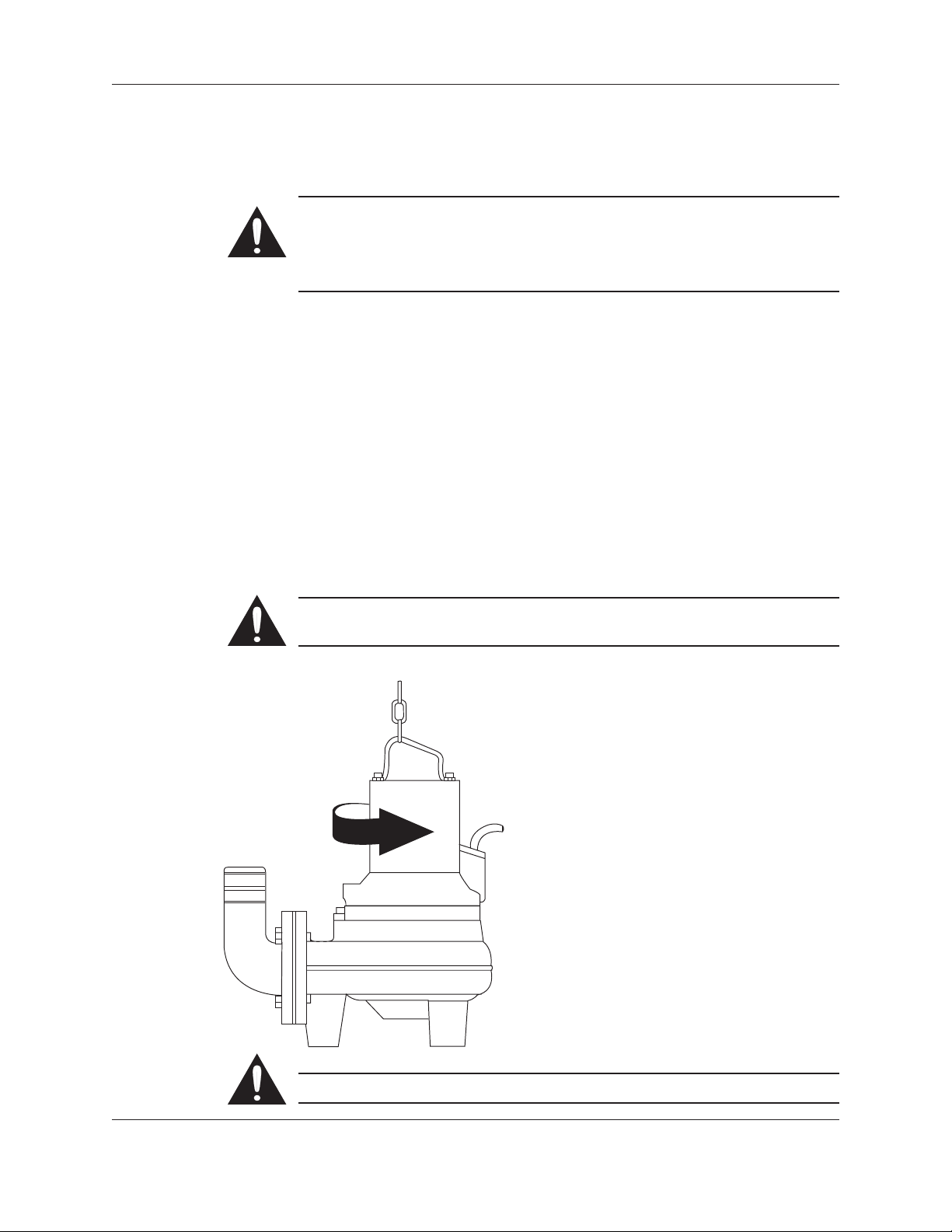
Check the direction of rotation. The impeller shall rotate clockwise, as viewed from above.
When started, the pump will jerk in the opposite direction to the direction in which the
impeller rotates. See the figure.
Operation
Starting Jerk
In the case of dry installation, check the direction of rotation through the inlet elbow access
cover.
Transpose two phase leads if the impeller rotates in the wrong direction (3~).
In some installations the pump surface and the surrounding liquid may be hot.
Bear in mind the risk of burn injuries.
Watch out for the starting jerk, which can be powerful.
1GA/2GA Installation, Operation and Maintenance Manual 17
Page 20

Care and Maintenance
X. Care and Maintenance
Before starting work on the pump, make sure that the pump is isolated from
the power supply and cannot be energized. This applies to the control circuit as
well.
NOTE FOR XP-VERSION: All work on the explosion-proof motor section must
be performed by personnel authorized by Goulds Water Technology. Goulds
Water Technology disclaims all responsibility for work done by untrained,
unauthorized personnel.
Make sure that the pump cannot roll or fall over and injure people or damage
property.
The following points are important in connection with work on the pump:
• Make sure that the pump has been thoroughly cleaned.
• Beware of the risk of infection.
• Follow local safety regulations.
The pump is designed for use in liquids which can be hazardous to health. In order to
prevent injury to the eyes and skin, observe the following points when working on the
pump:
• Always wear goggles and rubber gloves.
• Rinse the components in water after dismantling.
• The oil housing may be under pressure. Hold a rag over the oil screw (oil plug) to
prevent splatter.
Inspection
Proceed as follows if hazardous chemicals have splashed into your eyes:
• Rinse your eyes immediately in running water for 15 minutes. Hold your eyelids apart
with your fingers.
• Contact an eye specialist.
On your skin:
• Remove contaminated clothes.
• Wash your skin with soap and water.
• Seek medical attention, if required.
Regular inspection and preventive maintenance ensure more reliable operation.
The pump should be inspected at least once a year, but more frequently under sever
operating conditions.
Under normal operating conditions, the pump should have a major overhaul in a service
shop at least every third year for permanent installation and every year for portable pumps.
This requires special tools and should be done by an authorized service shop.
If the seals have been replaced an inspection of the oil is recommended after one week of
operation.
NOTE: Regular check of the condition of the lifting handle and chain is important.
18 1GA/2GA Installation, Operation and Maintenance Manual
Page 21

XI. Oil Change
A check of the condition of the oil can show whether there has been leakage. NOTE: Air/
oil mixture can be confused with water/oil mixture.
Insert a tube (or hose) into the oil hole. Cover the top end of the tube and take up a little oil
from the bottom.
Change the oil if it contains too much water, i.e. if it is heavily emulsied (cream-like), or if
the oil housing contains free water. Check again one week after changing the oil.
The oil housing may be under pressure. Hold a rag over the oil plug to prevent
splatter.
1. Lay the pump on its side on a bench or over two supports. Unscrew the oil housing screw
(oil plug) marked “oil out”. Emptying the oil must be done through the “oil out” hole.
2. Turn the pump. Unscrew the “oil in” oil hole screw/plug. In order to drain out all oil, the
pump must be raised upright for a short while during drainage.
3. Replace the o-rings under the oil housing screws (plugs) with new ones.
4. Install the “oil out” screw/plug and fill with oil through the other hole. It is important
that the oil be added through the hole marked “oil in” since the oil housing must contain some air for pressure equalization. The pump should be tilted slightly and put down
again horizontally in order to get the full amount of oil in.
Oil Change
A parafn oil with viscosity close to ISO VG15 is recommended (e.g. Mobil Whiterex
309). The pump is delivered from factory with this type of oil.
In applications where poisonous properties are of less concern, a mineral oil with viscosity up to ISO VG32 can be used.
Please see Parts List for the correct volume.
Figure 1
1GA/2GA Installation, Operation and Maintenance Manual 19
Page 22

Oil Change (continued)
Figure 2
Figure 3
20 1GA/2GA Installation, Operation and Maintenance Manual
Page 23

XII. Service Log
Service Log
Most Recent
Service Date Operation
Pump No.
Hours of
Remarks Sign.
1GA/2GA Installation, Operation and Maintenance Manual 21
Page 24

Notes
22 1GA/2GA Installation, Operation and Maintenance Manual
Page 25

Notes
1GA/2GA Installation, Operation and Maintenance Manual 23
Page 26

GOULDS WATER TECHNOLOGY LIMITED WARRANTY
This warranty applies to all wastewater pumps manufactured by Goulds Water Technology shown in this manual.
Any part or parts found to be defective within the warranty period shall be replaced at no charge to the dealer during the warranty period. The warranty
period shall exist for a period of twelve (12) months from date of installation or eighteen (18) months from date of manufacture, whichever period is
shorter.
A dealer who believes that a warranty claim exists must contact the authorized Goulds Water Technology distributor from whom the motor and control
was purchased and furnish complete details regarding the claim. The distributor is authorized to adjust any warranty claims utilizing the Goulds Water
Technology Customer Service Department.
The warranty excludes:
(a) Labor, transportation and related costs incurred by the dealer;
(b) Reinstallation costs of repaired equipment;
(c) Reinstallation costs of replacement equipment;
(d) Consequential damages of any kind; and,
(e) Reimbursement for loss caused by interruption of service.
For purposes of this warranty, the following terms have these definitions:
(1) “Distributor” means any individual, partnership, corporation, association, or other legal relationship that stands between Goulds Water Technology
and the dealer in purchases, consignments or contracts for sale of the subject motors and controls.
(2) “Dealer” means any individual, partnership, corporation, association, or other legal relationship which engages in the business of selling or leasing
motors and controls to customers.
(3) “Customer” means any entity who buys or leases the subject motors and controls from a dealer. The “customer” may mean an individual, partnership,
corporation, limited liability company, association or other legal entity which may engage in any type of business.
THIS WARRANTY EXTENDS TO THE DEALER ONLY.
Xylem, Inc.
2881 East Bayard Street Ext., Suite A
Seneca Falls, NY 13148
Phone: (866) 325-4210
Fax: (888) 322-5877
www.xyleminc.com/brands/gouldswatertechnology
Goulds is a registered trademark of Goulds Pumps, Inc. and is used under license.
© 2012 Xylem Inc. IM070 Revision Number 3 July 2012
 Loading...