

Page 1
Model
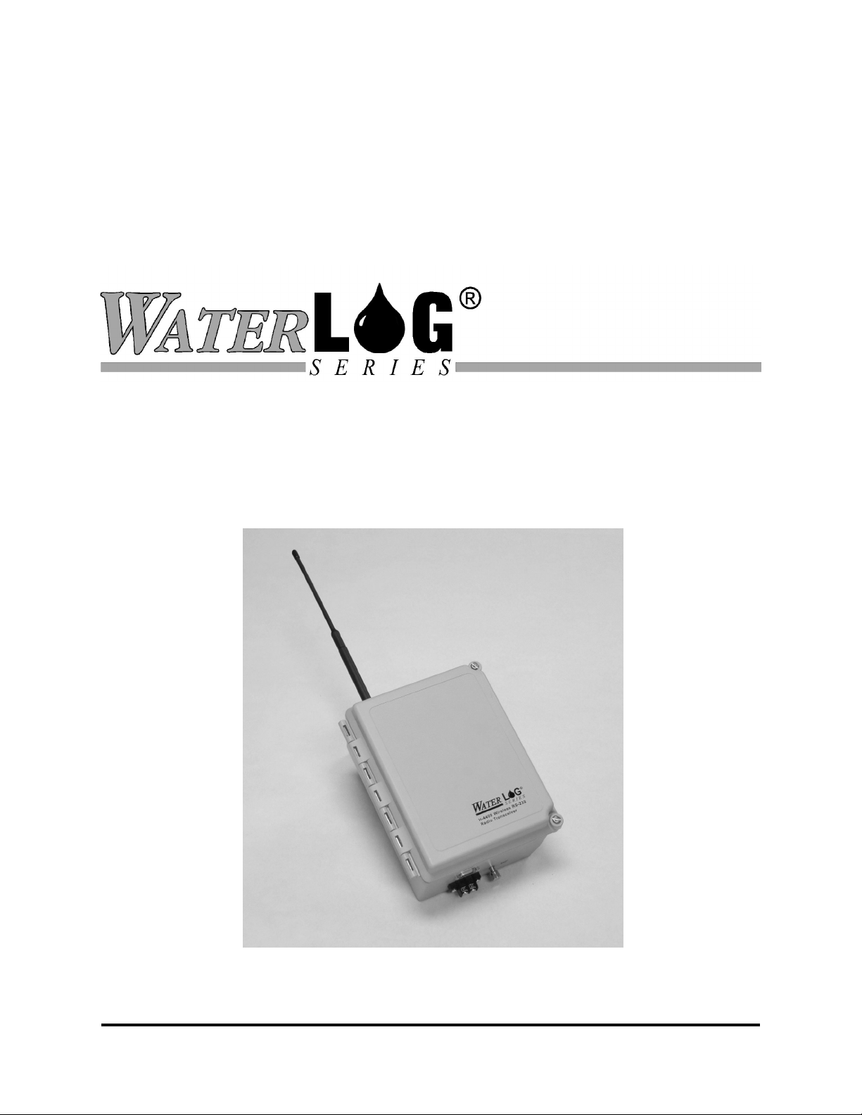
H-4400
RS-232 Data Radio
Owner's Manual
Version 1.0
75 West 100 South, Logan, Utah 84321 Phone: (435) 753-2212 Fax: (435) 753-7669 Web: http://www.waterlog.com E-mail: waterlog@waterlog.com
D E S I G N A N A L Y S I S A S S O C I A T E S , I N C .
Page 2

75 West 100 South, Logan, Utah 84321 Phone: (435) 753-2212 Fax: (435) 753-7669 Web: http://www.waterlog.com E-mail: waterlog@waterlog.com
D E S I G N A N A L Y S I S A S S O C I A T E S , I N C .
Page 3

Chapter 1
Introduction
1.0 Introduction
The W
often used to interface a data recorder with a remote “point-of-sale” display. The display allows
water level data to be displayed at a project office or other location remote from the data recorder
and water level sensing equipment.
The radio link uses modern direct sequence spread spectrum telemetry radios. Spread spectrum
technology is highly secure and has good interference immunity. The radio operates in the
license-free 900 Mhz ISM Band.
Two or more H-4400 modules are required; one connected to the data recorder (master) and one
or more located at the remote (slave) sites. The master and slave H-4400 modules are identical.
Normally the RS-232 data transfer is unidirectional - master to slave only. No device addresses
or setup is required, the master broadcasts to all slaves at the same time.
The radio internal to the H-4400 has a built-in electronic switch with controls power to the radio.
A push-on jumper on the radio selects either full power or power-save operation. When the
jumper is set to “Always On” the radio is powered continuously and draws approximately 60mA
continuous. When the jumper is set to “External (DTR)” the power is controlled by the RS-232
DSR input signal (pin-4).
ATER
LOG® H-4400 is a spread spectrum RS-232 radio bridge. The H-4400 radio link is
1.1 Operation
The H-4400 operates as a transparent 9600-baud RS–232 radio bridge. No programming or
special setup is needed. The radio in the slave station(s) must be jumpered for “Always On”. All
slave sites must be powered continuously or they will miss the data transmissions. The radio in the
master station can be jumpered for either “Always On” or “External (DTR)” depending on your
application. If the master station is connected to a data logger, the External DTR control setting
should be used to save power. If the external power control mode is selected, the data logger
must assert its DTR output before and during the transmission. Note a standard RS-232 cable
normally connects pin-4 (DTR) of a data terminal equipment (DTE) device [your data logger] to
pin-4 (DSR) of a data communications equipment (DCE) [the H-4400].
H-4400
RS-232 Data Radio 1-1
Page 4

1.2 Using the H-4400 as a Repeater
The spread spectrum radios require “line of sight” between the transmitter and receiver. For
installations where this is not practical a H-4400 can be configured to operate as a repeater.
Repeater
Master
Hill
Bubbler
The radio in the H-4400 has an internal buffer on its RS-232 input. If the RS-232 transmit and
receive signals are connected together the radio buffers, then re-transmits (echos) the RS-232
string. Bursts of up to 64 characters can be buffered. The repeater system works as follows:
1. The master station is powered up when the data recorder asserts DTR.
2. The data recorder sends a short RS-232 message string.
3. The master radio transmits the message string.
4. The repeater receives the message string.
5. The message string is routed back to the transmitter of the repeater with the loopback
connection
6. The repeater radio re-transmits the message.
7. Both the master and slave stations receive the message.
This scheme works because data transfer is only unidirectional. The echo back to the master
station is ignored by the data recorder.
Note: Depending on conditions the radio signal from the master station may sometimes be
received directly by the remote slave station. In this case the slave will receive two copies
of the RS-232 message, one from the master, the other from the repeater. When using the
radio link for a point-of-sale display, this will not cause a problem. The display will simply
update twice with the same message. This simple radio link cannot be used with more
than one repeater, the RS-232 message would bounce endlessly back and forth between
additional repeaters.
1-2 RS-232 Data Radio
H-4400
Page 5

Configure the repeater station as follows:
1. Set the power control jumper of the repeater to “Always On”. This causes the radio to be
powered continuously.
2. Install a special loopback connector on the RS-232 connector of the radio.
3. Make certain your +12V power source can provide 60mA continuous, 200mA for short
bursts.
1.3 Connecting the Antenna
The H-4400 may be used with a 50-ohm, 900 Mhz antenna providing the effective radiated power
is 6dB or less. The antenna connector is a reverse type-TNC connector which is required to
meet FCC part 15.203 regulations. A simple vertical whip antenna will work up to 2 or 3 miles.
Longer distances require a directional antenna with gain. A 6dB or 9dB YAGI will work fine, do
not use a 12dB model. At 900 MHz, RG58 type coaxial antenna feed lines have excessive loss
(1.8dB/10 feet). Consider using newer low loss RF cable such as Times Microwave LMR-400 or
similar (0.8dB/10 feet). The LMR-400 requires special RG8 connectors.
The H-44000 is packaged in a weather tight enclosure and is best mounted as close to the antenna
as possible. The H-4400 has a ground lug which should be connected to a good earth ground
with a heavy copper wire. The ground helps provides lightning protection for the radio, your
sensors and the data logger.
The H-4400 radios all operate at the same frequency. If multiple data logger sites are deployed,
make certain the radios of each separate logging site cannot “hear” each other. The radios can be
ordered with alternate frequencies, please contact the factory for further information.
Words of caution:
• Even though the master H-4400 operates in a low power mode, the transmitter
requires 200mA for short bursts. Make certain your wiring and battery is capable of
supplying sufficient current.
• Keep the lead wires as short as possible.
• Use shielded cables in noisy environments.
• Connect the ground post to a good earth ground.
H-4400
RS-232 Data Radio 1-3
Page 6

1.4 Troubleshooting
The radios can be difficult to field test when operating with a data logger due to the intermittent
short bursts of data. The radio system can be more throughly tested with the aid of a lap-top
computer or RS-232 terminal. With the following setup you can transmit ASCII messages or
other test data while adjusting or aligning the antennas. The radio link is tested by connecting a
computer terminal to one radio and connecting a loopback connector to the other. With this
setup, one person can test both up-link and down-link communication paths.
The radios have a standard RS-232C interface which operates at 9600 baud. With a straight-thru
9-pin RS-232 cable, connect one of the radios to a laptop computer or terminal. The radios have
a female DB9 connector, pin-2 is received data output and pin-3 is transmit data input. The other
radio in the link to be tested must be setup for loopback operation. Do this by installing a
loopback test connector or connecting a jumper between pins 2 & 3. Set the power control
jumpers of both radios for “Always On”.
The wireless link is best tested with a test program provided by the radio manufacturer. The test
program “X-CTU” can be downloaded from the www.maxstream.net website. X-CTU
automatically tests the wireless link and provides a success/fail display of each data packet. Make
sure your computer is set for full-duplex, 9600 Baud.
Alternatively, you can use a terminal program such as XTALK or PROCOMM to test the radio
link. Make sure your computer or terminal is set for full-duplex, 9600 Baud. Test the radio link by
typing characters and checking for the proper echoed response. As you type, the characters are
transmitted to the remote station then re-transmitted back to the local station and displayed on
your screen. Both up-link and down-link paths are tested at the same time.
1-4 RS-232 Data Radio
H-4400
Page 7

1.5 FCC Restrictions
This equipment has been tested and found to comply with the limits for a Class B digital device,
pursuant to Part 15 of the FCC Rules. These limits are designed to provide reasonable protection
against harmful interference in a residential installation. This equipment generates, uses, and can
radiate radio frequency energy and, if not installed and used in accordance with the instructions,
may cause harmful interference to radio communications. However, there is no guarantee that
interference will not occur in a particular installation. If this equipment does cause harmful
interference to radio or television reception, which can be determined by turning the equipment
off and on, the user is encouraged to try to correct the interference by one or more of the
following measures:
• Reorient or relocate the receiving antenna.
• Increase the separation between the equipment and receiver.
• Connect the equipment into an outlet on a circuit different from that to which the
receiver is connected.
• Consult the dealer or an experienced Radio/TV technician for help.
Declaration of Conformity to Part 15, subpart B
The following declaration applies:
MaxStream Inc. model 9Xstream frequency hopping spread spectrum transceiver.
This device complies with part 15 of the FCC rules. Operation is subject to the following two
conditions:
1. This device may not cause harmful interference, and.
2. This device must accept any interference received, including interference that
may cause undesired operation.
The responsible party for this declaration is:
MaxStream Inc.
1206 W. 1680 W.
Orem, UT 84058
(801)765-9885
H-4400
RS-232 Data Radio 1-5
 Loading...