

Page 1
Model
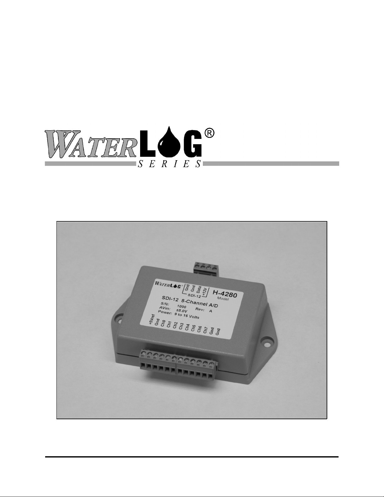
H-4280
8-Channel SDI-12 Analog Input Module
Owner's Manual
Version 1.0
75 West 100 South, Logan, Utah 84321 Phone: (435) 753-2212 Fax: (435) 753-7669 Web: http://www.waterlog.com E-mail: waterlog@waterlog.com
D E S I G N A N A L Y S I S A S S O C I A T E S , I N C .
Page 2

75 West 100 South, Logan, Utah 84321 Phone: (435) 753-2212 Fax: (435) 753-7669 Web: http://www.waterlog.com E-mail: waterlog@waterlog.com
D E S I G N A N A L Y S I S A S S O C I A T E S , I N C .
Page 3

User Agreement/
W
ATER
1. NATURE OF THE PRODUCT
This agreement accompanies an electronic sensor system comprising firmware, circuitry and other
electronic equipment in an enclosed housing, and packaged together with written instructional materials.
The packaged electronic circuitry and instructional materials herein are collectively referred to as the
“PRODUCT.” The PRODUCT is made available from DESIGN ANALYSIS ASSOCIATES, INC., of
75 West 100 South, Logan, Utah 84321 (hereinafter referred to as “DESIGN ANALYSIS”), and contains
information and embodies technology that is confidential and proprietary to DESIGN ANALYSIS, and the
availability and use of the PRODUCT is extended to you, the USER, solely on the basis of the terms of
agreement which follow.
2. ACKNOWLEDGMENTS BY USER
Opening the package which encloses the accompanying PRODUCT indicates your acceptance of the terms
and conditions of this agreement and constitutes an acknowledgment by you of the confidential and
proprietary nature of the rights of DESIGN ANALYSIS in the PRODUCT.
3. DUTIES OF YOU, THE USER
In consideration for the access to and use of the PRODUCT extended to you by DESIGN ANALYSIS and
to protect the confidential and proprietary information of DESIGN ANALYSIS, USER agrees as follows:
LOG® Warranty
(a) USER agrees that they will not remove from the exterior of the housing of the PRODUCT
any safety warnings or notices of proprietary interest placed thereon by DESIGN
ANALYSIS.
(b) USER agrees that they shall not disassemble or otherwise reverse engineer the
PRODUCT.
(c) USER agrees to treat the PRODUCT with the same degree of care as USER exercises in
relation to their own confidential and proprietary information.
4. TERM
USER may enjoy these rights only as long as their possession of the PRODUCT shall continue to be
rightful. These rights will cease if the PRODUCT is returned to DESIGN ANALYSIS under the terms of
any redemption offer, warranty, or money-back guarantee, or if USER transfers the PRODUCT to another
party on terms inconsistent with this agreement.
5. LIMITED WARRANTY
(b) What is Covered
DESIGN ANALYSIS warrants that for a period of twelve months from the time of purchase the
functions to be performed by the PRODUCT will be substantially in compliance with USER
documentation. DESIGN ANALYSIS also warrants that the PRODUCT will be free from defects
in materials and workmanship for a period of ONE YEAR from the date of purchase.
(b) What USER Must Do
If the product fails to satisfy the above warranty, USER must notify DESIGN ANALYSIS in
H-4280
User Agreement/W
ATER
LOG® Warranty W-1
Page 4

writing within the applicable period specified above and reasonably cooperate with the directions
they received from DESIGN ANALYSIS.
(c) What DESIGN ANALYSIS Will Do
DESIGN ANALYSIS will repair the PRODUCT or will endeavor to provide a replacement of
same within a reasonable period of time. In the event that DESIGN ANALYSIS is unable to make
the necessary repairs or replacement within a reasonable period of time, the original purchase price
will be refunded upon the return of the PRODUCT to DESIGN ANALYSIS.
(d) Limitations
(i) THE ENTIRE REMEDY FOR BREACH OF THIS LIMITED WARRANTY
SHALL BE LIMITED TO REPLACEMENT OF THE DEFECTIVE
PRODUCT OR REFUNDING OF THE PURCHASE PRICE, AS SET FORTH
ABOVE. IN NO EVENT WILL THE LIABILITY OF DESIGN ANALYSIS
TO USER OR TO ANY OTHER PARTY EXCEED THE ORIGINAL
PURCHASE PRICE OF THE PRODUCT, REGARDLESS OF THE FORM OF
THE CLAIM.
(ii) EXCEPT FOR THE EXPRESS WARRANTIES ABOVE, DESIGN ANALYSIS
SPECIFICALLY DISCLAIMS ALL OTHER WARRANTIES, INCLUDING,
WITHOUT LIMITATION, ALL IMPLIED WARRANTIES OF
MERCHANTABILITY AND FITNESS FOR A PARTICULAR PURPOSE.
(iii) UNDER NO CIRCUMSTANCES WILL DESIGN ANALYSIS BE LIABLE
FOR SPECIAL, INCIDENTAL, CONSEQUENTIAL, INDIRECT, OR ANY
OTHER DAMAGES OR CLAIMS ARISING FROM THE USE OF THIS
PRODUCT, THIS INCLUDES LOSS OF PROFITS OR ANY OTHER
COMMERCIAL DAMAGES, EVEN IF ADVISED OF THE POSSIBILITY OF
SUCH DAMAGES. IN NO EVENT WILL DESIGN ANALYSIS BE LIABLE
FOR ANY CLAIMS, LIABILITY, OR DAMAGES ARISING FROM
MODIFICATION MADE THEREIN, OTHER THAN BY DESIGN
ANALYSIS.
(iv) THIS LIMITED WARRANTY GIVES USER SPECIFIC LEGAL RIGHTS.
USER MAY ALSO HAVE OTHER RIGHTS WHICH VARY FROM STATE
TO STATE. SOME STATES DO NOT ALLOW LIMITATIONS ON HOW
LONG AN IMPLIED WARRANTY LASTS OR THE EXCLUSION OF
INCIDENTAL OR CONSEQUENTIAL DAMAGES, SO THOSE
LIMITATIONS OR EXCLUSIONS MAY NOT APPLY.
6. GOVERNING LAW
This Agreement and its validity and interpretation shall be governed by the laws of the State of Utah,
notwithstanding any choice of law rules of Utah or any other state or jurisdiction.
W-2 User Agreement/W
ATER
LOG® Warranty
H-4280
Page 5

Chapter 1
Introduction
1.0 Introduction
The W
ATER
LOG® Model H-4280 is a 12-bit, 8-channel, analog input module. The module is an intelligent
SDI-12 “sensor” and can provide measurement data in engineering units such as feet or meters.
The H-4280 is easy to use and works with any data recorder/logger with a SDI-12 interface. The module
is powered from the +12V wire of the 3-wire SDI-12 bus. The SDI-12 (Serial Digital Interface 1200–baud)
is ideal for data logging applications with the following requirements:
Battery powered operation with minimal current drain
Measurement data is transmitted digitally over long cable lengths without error
Multiple sensors on a simple three-wire cable
Up to 250 feet of cable between a sensor and the data recorder (Use of a H-423, SDI-12
to RS485 or H-4500 fiberoptic media converter extends the range to 1000's of feet)
The H-4280 has the following features:
Works with any SDI-12 compliant data logger
8-analog input channels
Supports unipolar (0-5V), bipolar (±5V) and differential (0-5V & ±5V) operation.
12-bit A/D makes up to 700 measurements per second
Precision 5.0V reference output for sensor excitation
Sensor warmup time (excitation) is programmable
Low power sleep operation (<100A)
Programmable data averaging
Programmable slope, offset and format settings for each of the 8-channels
Built in extended SDI-12 commands for setup and configuration.
Plug-in terminal connectors
1.1 Description
The H-4280 is primarily used to interface simple analog sensors to a SDI-12 compliant data logger. Many
sensors such as potentiometers, thermistors, and pressure sensors can be connected directly to the H-4280.
Each channel can be configured with a y=mX+b linear equation to convert the input voltage into user units
such as temperature, pressure, feet or meters. The linear equation has a slope (m) term and an offset (b)
term. At the factory the slope is set to 1.00 and the offset to 0.00, with these values the measurement will
be in units of Volts. The linear equation will work for sensors such as potentiometers, shaft encoders and
4-20mA transducers with linear outputs. The y=mX+b equation will not work with thermocouples,
thermistors and other sensors having a non-linear response. For these sensors, leave the slope = 1.0, offset
= 0.0 and perform the more complex math operations in your data logger.
1.2 Input Settings
When the data logger issues an aM! command to initiate a measurement, the H-4280 makes 8measurements, one for each channel. Each channel can be configured to make Unipolar/Bipolar and
Single/Differential measurements. The results of the 8-measurements are placed in the sensor buffer and
can be collected with aD0! and aD1! commands.
H-4280
Introduction 1-1
Page 6

Unipolar 0 to 5.0 Volts (resolution is 1.2mV)
Bipolar: ±5.0 Volts (resolution is 2.4mV)
Single Ended: Measurement is referenced to ground
Differential: Measures the difference between two adjacent input channels (0-1, 2-3, 4-5, 6-7)
The H-4280 always makes 8-measurements, even if one or more of the channels is configured for a
differential measurement. For example; if Channel 0 is configured for a differential measurement, the
Channel 0 measurement is determined by the input voltage on both Channel 0 & 1. Subsequently a
measurement is made for Channel 1, with the results determined separately by the settings of Channel 1.
Normally if Channel 0 is configured for a differential measurement, the results of the adjacent channel
measurement (Channel 1) is ignored by the data logger (and vice versa).
1.3 Single-Ended Analog Inputs
A single-ended analog measurement is one which is referenced to ground. The H-4280 can make up to eight
single-ended measurements. Both unipolar and bipolar measurements can be selected. The 12-position
input connector has 3-terminals for making ground connections. Unused inputs may be left floating,
however the measurement data from unused inputs channels is undefined and will drift.
1.4 Differential Analog Inputs
A differential analog measurement is one which measures the difference between two input terminals. The
two terminals have positive and negative input response respectively. The H-4280 can make up to 4
differential measurements. Both unipolar and bipolar measurements can be selected. If the (+) input will
always more positive than the (-) input, set the channel to “unipolar”. The unipolar setting has the best
resolution. If the (+) can be less positive than the (-) input, set the channel to “bipolar”. The bipolar setting
allows the measurement to go negative but has the shortcoming of 1-bit less resolution.
1.5 Excitation Output
The H-4280 has a precision 5.00V excitation output terminal for powering potentiometers, thermistors and
other sensors. The +5Vref terminal is internally connected to the A/D converter. Measurements made with
resistance sensors powered from the +5Vref terminal will be “ratio metric” in that errors in the absolute
value of the reference cancel out. The +5Vref output is normally turned off to save power while the
module is in its sleep mode and is switched on before a measurement is made. The “warmup time” is a
programmable delay (1 to 999 seconds) which elapses before the first measurement is made. If desired, the
excitation output can be programmed to remain active while the module is asleep. The +5Vref terminal is
for powering potentiometers, thermistors and other low current senors. Do not draw more than 50mA from
the +5Vref terminal.
1.6 Sensors With Current Output
The H-4280 measures input voltage. Sensors which output current can be connected to the H-4280 with
the aid of a shunt resistor. For example, a 4-20mA sensor can be interfaced by connecting a precision 250
ohm shunt resistor between the input and a ground terminal. When the sensor is transmitting its 20mA
maximum output the H-4280 will input 5.0Volts: ( 5.0V = .020mA x 250 Ohms).
1-2 Introduction
H-4280
Page 7

1.7 Averaging
The H-4280 can make up to 700 measurements/second (per 8-channels) The module makes multiple high
speed measurements, averages the results (simple mean) and reports one measurement per channel. The
number of samples can be programmed from 1 to 65535, the H-4280 comes from the factory configured to
make 100 samples for each channel (100 x (1/700)=0.142 seconds ). The number of samples per
measurement (1-65535) is the same for all 8-channels.
H-4280
Introduction 1-3
Page 8

1-4 Introduction
H-4280
Page 9
Installation And Setup
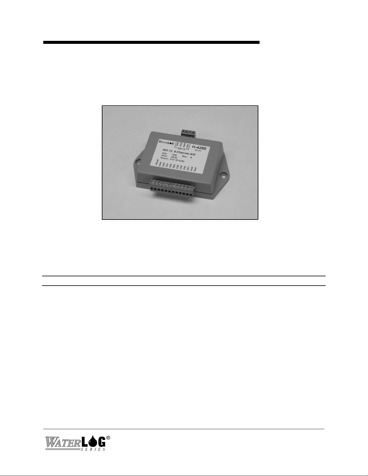
2.1 Installing The H-4280
The W
ATER
LOG® H-4280 is an 8-channel analog to digital SDI-12 “sensor”. Many sensors such as
potentiometers, thermistors, and pressure sensors can be connected directly to the H-4280
Chapter 2
2.2 General Installation Recommendations
The H-4280 housing and connectors are not weather tight. The H-4280 must be installed in a protected
location or a weather tight enclosure. The housing has a 4-terminal connector for making power and SDI12 connections and a 2-segment, 12-terminal connector for connecting the analog inputs. The connectors
can be detached while making the connections.
Caution: Remove all power from the unit before making any connections.
Before beginning the installation take a minute to plan out your station grounding and wiring scheme. Use
a single point ground system design to avoid having high current (power) flowing into or out of the ground
terminals of the analog input connector. If your sensors have separate signal and power connections,
connect only the signal and its ground reference to the input connector. Use shielded cables where possible.
Use a shielded, twisted-pair cable when making connections to a differential input. Install lightening and
other transient voltage protection if the sensors and wiring are exposed to damage. Power the sensors from
the same battery or power supply which supplies the data logger, this makes certain input voltages to the
H-4280 are not present if the H-4280 is powered off.
H-4280
Installation And Maintenance 2-1
Page 10

2.3 +5Vref Output
The H-4280 has a precision 5.00V excitation output terminal for powering potentiometers, thermistors and
other sensors. The +5Vref terminal is internally connected to the A/D converter. Measurements made with
resistance sensors powered from the +5Vref terminal will be “ratio metric” in that errors in the absolute
value of the reference cancel out. The +5Vref output is normally turned off to save power while the
module is in its sleep mode and is switched on before a measurement is made. The “warmup time” is a
programmable delay (1 to 999 seconds) which elapses before the first measurement is made If desired, the
excitation output can be programmed to remain active while the module is asleep. The +5Vref terminal is
for powering potentiometers, thermistors and other low current senors. Do not draw more than 50mA from
the +5Vref terminal.
The warmup delay is configured with the extended “aXRWT!” and “aXWWTnnn! commands. The
+5Vref power mode during sleep is configured with the extended “aXRPM!” and “aXWPMnn! commands.
See Chapter 3 for details.
2.4 Averaging
The H-4280 can make up to 700 measurements/second (per 8-channels) The module makes multiple high
speed measurements, averages the results and reports one measurement per channel. The number of
samples can be programmed from 1 to 65535, the H-4280 comes from the factory configured to make 100
samples for each channel (100 x (1/700)=0.142 seconds ). The number of samples per measurement (1-
65535) is the same for all 8-channels. This setting is configured with the extended “aXRMC!” and
“aXWMCnnn! commands. See Chapter 3 for details.
2.5 Channel Settings
Each channel can be configured to make Unipolar/Bipolar and Single/Differential measurements.
Unipolar 0 to 5.0 Volts (resolution is 1.2mV)
Bipolar: ±5.0 Volts (resolution is 2.4mV)
Single: Measurement is referenced to ground
Differential: Measures the difference between two adjacent input channels
These and other settings are configured with the extended “aXRCn!” and “aXWCn! commands. See
Chapter 3 for details.
2-2 Installation And Maintenance
H-4280
Page 11

2.6 Slope & Offset
Each channel can be configured with a y=mX+b linear equation to convert the input voltage into user units
such as pressure, feet or meters. The linear equation has a slope (m) term and an offset (b) term. At the
factory the slope is set to 1.00 and the offset to 0.00, with these settings the measurement will be in units
of Volts. The linear equation will work for sensors such as potentiometers, position sensors and 4-20mA
transducers with linear outputs. The y=mX+b equation will not work with thermocouples, thermistors and
other sensors having a non-linear response. For these sensors, leave the slope = 1.0, offset = 0.0 and
perform the more complex math operations in your data logger. The slope and offset settings are
configured with the extended “aXROn!” & “aXWOn nn!”, “aXRSn!” & “aXWSn nn!” or the “aXRCn!”
& “aXWCn! commands. See Chapter 3 for details.
2.7 Data Format
The number of digits printed past the decimal point can be configured for each channel. For example if
Digits = 2 for a particular channel the respective data will have two digits beyond the decimal point (x.xx).
At the factory all 8-channels are set for 3-digits beyond the decimal point. These settings are configured
with the extended “aXRCn!” & “aXWCn! commands. See Chapter 3 for details.
2.8 Programming Your SDI-12 Data Recorder
You must prepare your data recorder to receive and record the H-4280 data. Since data recorders differ,
refer to your data recorder manufacturer's directions. In general, program the data recorder to input 8values via the SDI-12 port. All eight parameters do not need to be actually recorded. Your data recorder
must issue an “aM!” command, then collect the data with “aD0!" and “aD1!" commands, as explained in
Chapter 3. Four parameters are returned in response to the “aD0!” command and four more with the
“aD1!” command.
The H-4280 places eight parameters in its data buffer:
a+A.AAA+BB.BBB+C.CCC+D.DDD+E.EEE+F.FFF+G.GGG+H.HHH<CR><LF>
Where: a = SDI-12 address 0-9, A-Z
A.AAA = Channel 0
B.BBB = Channel 1
C.CCC = Channel 2
D.DDD = Channel 3
E.EEE = Channel 4
F.FFF = Channel 5
G.GGG = Channel 6
H.HHH = Channel 7
H-4280
Installation And Maintenance 2-3
Page 12

2.9 Testing
For preliminary testing a simple potentiometer can be used to simulate one or more sensors. Connect one
end of the potentiometer resistor to a ground terminal and the other end to the +5Vref terminal. Connect
the potentiometer wiper to one of the input channels. Make several measurements while adjusting the
potentiometer and check for the expected results.
2.10 “XTEST”
The “XTEST” command is used for installation or production testing and requires the use of a H-4191
Sidekick interface and a PC. This command causes the H-4280 to transmit unsolicited real-time data for
testing purposes. The test mode is used to help troubleshoot the installation by providing a continuous
readout of measurement data. This is not compliant with the SDI-12 specification and is not used with data
loggers.
To activate the test mode, send the command “aXTEST!” from the PC. The H-4280 will enter the test
mode and make and print continuous measurements. The test mode is exited by sending a break or any
new command on the SDI-12 bus. For example:
0: +1.202 +3.222 +1.234 +2.345 +2.677 +3.333 +1.202 +1.202
0: +1.202 +3.222 +1.234 +2.345 +2.677 +3.333 +1.202 +1.202
0: +1.202 +3.222 +1.234 +2.345 +2.677 +3.333 +1.202 +1.202
0: +1.202 +3.222 +1.234 +2.345 +2.677 +3.333 +1.202 +1.202
2-4 Installation And Maintenance
H-4280
Page 13

Chapter 3
SDI-12 Command and Response Protocol
3.0 SDI-12 Command and Response Protocol
This is a description of the Serial Digital Interface (SDI-12) Command and Response Protocol used by the
W
ATER
LOG® Series Model H-4280 sensor. Included is a description of the commands and data format
supported by the H-4280.
Refer to the document "A SERIAL DIGITAL INTERFACE STANDARD FOR HYDROLOGIC AND
ENVIRONMENTAL SENSORS.” Version 1.2 April 12, 1996 Coordinated by the SDI-12 Support
Group, 135 East Center, Logan, Utah.
During normal communication, the data recorder sends an address together with a command to the H-4280
SDI-12 sensor. The H-4280 then replies with a "response." In the following descriptions, SDI-12
commands and responses are enclosed in quotes. The SDI-12 address and the command/response
terminators are defined as follows:
"a" Is the sensor address. The following ASCII Characters are valid addresses: "0-9",
"A-Z", "a-z", "*", "?". Sensors will be initially programmed at the factory with the
address of "0" for use in single sensor systems. Addresses "1 to 9" and "A to Z"
or "a to z" can be used for additional sensors connected to the same SDI-12 bus.
Address "*" and "?" are "wild card" addresses which select any sensor, regardless
of its actual address.
Notes:
"!" Is the last character of a command block.
"<cr><lf>" Are carriage return (0D) hex and line feed (0A) hex characters. They are the last
two characters of a response block.
• All commands/responses are upper-case printable ASCII characters.
• Commands must be terminated with a "!" character.
• Responses are terminated with <cr><lf> characters.
• The command string must be transmitted in a contiguous block with no gaps of more than
1.66 milliseconds between characters.
H-4280
SDI-12 Command and Response Protocol 3-1
Page 14

3.1 Master SDI-12 Command List
Standard SDI-12 commands
Command Description
aM! Make Measurement
aC! Make Concurrent Measurement
aD0! and aD1! Send Data
aV! Verify Sensor
aI! Send Identification
Extended SDI-12 commands unique to the H-4280
Command Description
aAn! Change sensor address
aXRCn! Read configuration of channel n
aXWCn! Write configuration of channel n
aXSCSn ddd! Set current “stage” of channel n
aXRSn! Read Slope of channel n
aXWSn ddd! Write Slope of channel n
aXROn! Read Offset of channel n
aXWOn ddd! Write Offset of channel n
aXRMC! Read Mean_Count
aXWMCnnn! Write Mean_Count
aXRPM! Read Power_Mode
aXWPMn! Write Power_Mode
aXRWT! Read Warmup_Time
aXWWTnnn! Write Warmup_Time
aXTEST! Initiate a repeating test printout
3-2 SDI-12 Command and Response Protocol
H-4280
Page 15

3.2 Measure Command
The Measure Command causes a measurement sequence to be performed. Data values generated in
response to this command are stored in the sensor's buffer for subsequent collection using "D" commands.
The data will be retained in the sensor until another "M", " C", or "V" command is executed.
Command Response Description
"aM!" "atttn<cr><lf>" Initiate measurement
Where:
a is the sensor address ("0-9", "A-Z", "a-z", "*", "?").
M is an upper-case ASCII character
ttt is a three digit integer (000-999) specifying the maximum time, in seconds, the
sensor will take to complete the command and have measurement data available in
its buffer.
n is a single digit integer (0-9) specifying the number of values that will be
placed in the data buffer. If "n" is zero (0), no data will be available using
subsequent "D" commands.
Upon completion of the measurement, a service request "a<cr><lf>" is sent to the data recorder indicating
the sensor data is ready. The data recorder may wake the sensor with a break and collect the data any time
after the service request is received or the specified processing time has elapsed.
Example of a H-4280 "aM!" command:
Command Response Time Values Description
"aM!" "a0038<cr><lf>" 3 sec 8 Make measurement
Subsequent Command Response
"aD0" a+A.AAA+B.BBB+C.CCC+D.DDD<CR><LF>
"aD1" a+E.EEE+F.FFF+G.GGG+H.HHH<CR><LF>
Where: A.AAA = Channel 0 Voltage
B.BBB = Channel 1 Voltage
C.CCC = Channel 2 Voltage
D.DDD = Channel 3 Voltage
E.EEE = Channel 4 Voltage
F.FFF = Channel 5Voltage
G.GGG = Channel 6 Voltage
H.HHH = Channel 7 Voltage
H-4280
SDI-12 Command and Response Protocol 3-3
Page 16

3.3 Concurrent Measurement Command
This is a new command for the Version 1.2 SDI-12 Specification. A concurrent measurement is
one which occurs while other SDI-12 sensors on the bus are also taking measurements. This
command is similar to the “aM!” command, however, the nn field has an extra digit and the sensor
does not issue a service request when it has completed the measurement. Communicating with
other sensors will NOT abort a concurrent measurement. Data values generated in response to
this command are stored in the sensor's buffer for subsequent collection using "D" commands. The
data will be retained in the sensor until another "M", "C", or "V" command is executed.
Command Response Description
"aC!" "atttnn<cr><lf>" Initiate measurement
Where:
a is the sensor address ("0-9", "A-Z", "a-z", "*", "?").
C is an upper-case ASCII character
ttt is a three digit integer (000-999) specifying the maximum time, in seconds, the
sensor will take to complete the command and have measurement data available in
its buffer.
nn is a two digit integer (00-99) specifying the number of values that will be
placed in the data buffer. If "n" is zero (0), no data will be available using
subsequent "D" commands.
The data recorder may wake the sensor with a break and collect the data anytime after the
specified processing time has elapsed.
3-4 SDI-12 Command and Response Protocol
H-4280
Page 17

3.4 Send Data Command
The Send Data command returns sensor data generated as the result of previous "aM!", "aC!", or
"aV!" commands. Values returned will be sent in 33 characters or less. The sensor's data buffer
will not be altered by this command.
Command Response
"aD0!" through "aD9!" "apd.d ... pd.d<cr><lf>"
Where:
a is the sensor address ("0-9", "A-Z", "a-z", "*", "?").
D0..D9 are upper-case ASCII characters.
p Is a polarity sign (+ or -)
d.d represents numeric digits before and/or after the decimal. A decimal may be
used in any position in the value after the polarity sign. If a decimal is not
used, it will be assumed to be after the last digit.
For example: +3.29 +23.5 -25.45 +300
If one or more values were specified and a "aD0!" returns no data (<CR><LF> only), it means that
the measurement was aborted and a new "M" command must be sent.
Example of a H-4280 "aM!" command:
Command Response Time Values Description
"aM!" "a0038<cr><lf>" 3 sec 8 Make measurement
Subsequent Command Response
"aD0" a+A.AAA+B.BBB+C.CCC+D.DDD<CR><LF>
"aD1" a+E.EEE+F.FFF+G.GGG+H.HHH<CR><LF>
Where:
A.AAA = Channel 0 Voltage
B.BBB = Channel 1 Voltage
C.CCC = Channel 2 Voltage
D.DDD = Channel 3 Voltage
E.EEE = Channel 4 Voltage
F.FFF = Channel 5Voltage
G.GGG = Channel 6 Voltage
H.HHH = Channel 7 Voltage
H-4280
SDI-12 Command and Response Protocol 3-5
Page 18

3.5 Continuous Measurements
This is a new command for the Version 1.2 SDI-12 Specification. Sensors that are able to continuously
monitor the phenomena to be measured, such as a cable position, do not require a start measurement
command. They can be read directly with the R commands (R0!...R9!). The R commands work exactly like
the D (D0!...D9!) commands. The only difference is that the R commands do not need to be preceded with
an M command.
The H-4280 does not support the aR0! continuous measurement commands because the measurement and
math operations require several seconds to complete..
3.5 Send Acknowledge Command
The Send Acknowledge Command returns a simple status response which includes the address of the sensor.
Any measurement data in the sensor's buffer is not disturbed.
Command Response
"a!" "a<cr><lf>"
Where: a Is the sensor address ("0-9", "A-Z", "a-z", "*", "?").
3-6 SDI-12 Command and Response Protocol
H-4280
Page 19

3.6 Initiate Verify Command
The Verify Command causes a verify sequence to be performed. The result of this command is similar to
the "aM!" command except that the values generated are fixed test data and the results of diagnostic
checksum tests. The data generated in response to this command is placed in the sensor's buffer for
subsequent collection using "D" commands. The data will be retained in the sensor until another "M", "C",
or "V" command is executed.
Command Response Description
"aV!" "atttn<cr><lf>" Initiate verify sequence
Where:
a is the sensor address ("0-9", "A-Z", "a-z", "*", "?").
V is an upper-case ASCII character.
ttt is a three digit integer (000-999) specifying the maximum time, in seconds, the sensor will
take to complete the command and have data available in its buffer.
n is a single digit integer (0-9) specifying the number of values that will be
placed in the data buffer. If "n" is zero (0), no data will be available using
subsequent "D" commands
Example of a "aV!" command:
Command Response Time Values Description
"aV!" "a0013<cr><lf>" 1 sec 3 Return fixed data and diagnostic data for testing
purposes.
Subsequent Command Response
"aD0" a+123.456+78.9+y<cr><lf>
Key Description Units
+123.456 Fixed test data
+78.9 Fixed test data
y ROM checksum test 0 = Failed, 1 = Passed
H-4280
SDI-12 Command and Response Protocol 3-7
Page 20

3.7 Send Identification Command
The Send Identification Command responds with sensor vendor, model, and version data. Any
measurement data in the sensor's buffer is not disturbed.
Command Response
"aI!" "allccccccccmmmmmmvvvxx...xx<cr><lf>"
Where:
a is the sensor address ("0-9", "A-Z", "a-z", "*", "?").
I is an upper-case ASCII character.
ll is the SDI-12 version compatibility level, e.g. version 1.2 is represented as
"12".
cccccccc is an 8 character vendor identification to be specified by the vendor and
usually in the form of a company name or its abbreviation.
mmmmmm is a 6 character field specifying the sensor model number.
vvv is a 3 character field specifying the sensor version number.
xx...xx is an optional field of up to a maximum of 13 characters to be used for
serial number or other specific sensor information not relevant to operation
of the data recorder.
Example of a "aI!" command:
"a12 DAA H-4280vvvS#nnnnnnVkkk<cr><lf>"
H-4280 implementation of the optional 13 character field:
S#nnnnnnVkkk
Where:
"nnnnnn is a six character sensor serial number
"kkk" is a three digit sensor firmware revision level
(12 bytes total)
3-8 SDI-12 Command and Response Protocol
H-4280
Page 21

3.8 Change Sensor Address Command
The Change Sensor Address Command allows the sensor address to be changed. The address is
stored in non-volatile EEPROM within the sensor. The H-4280 will not respond if the command
was invalid, the address was out of range, or the EEPROM programming operation failed.
Command Response Description
"aAn! "n<cr><lf>" Change sensor address
Where:
a is the current (old) sensor address ("0-9", "A-Z", "a-z", "*", "?"). An
ASCII "*" may be used as a "wild card" address if the current address is
unknown and only one sensor is connected to the bus.
A is an upper-case ASCII character.
n is the new sensor address to be programmed ("0-9", "A-Z").
NOTE: To verify the new address use the "Identify Command."
Example of a "Change Sensor Address" command:
Command Response Description
"aA2!" "2<cr><lf>"
Change sensor address to "2"
H-4280
SDI-12 Command and Response Protocol 3-9
Page 22

3.9 Extended Read Channel_Config and Write Channel_Config
Each of the 8-input channels can be configured to make Unipolar/Bipolar and Single/Differential
measurements. Use the “aXRC!” and “aXWC!” extended commands to monitor or change the
configuration for each input channel. The Slope, Offset and SDI_Digits for each channel can also
be configured with these commands.
The H-4280 always makes 8-measurements, even if one or more of the channels is configured for
a differential measurement. For example: if Channel 0 is configured for a differential
measurement, the Channel 0 measurement is determined by the input voltage on both Channel 0 &
1. Subsequently a measurement is made for Channel 1, with the results determined separately by
the settings of Channel 1. Normally if Channel 0 is configured for a differential measurement, the
results of the adjacent channel measurement (Channel 1) is ignored by the data logger (and vice
versa).
Differential Channel Selection
Chan 0 1 2 3 4 5 6 7
0
1
2
3
4
5
6
7
For differential measurements; if the (+) input will always more positive than the (-) input, set the
channel to “unipolar”. The unipolar setting has the best resolution. If the (+) can be less positive
than the (-) input, set the channel to “bipolar”. The bipolar setting allows the measurement to go
negative but has the shortcoming of 1-bit less resolution.
+ -
- +
+ -
- +
+ -
- +
+ -
- +
3-10 SDI-12 Command and Response Protocol
H-4280
Page 23

The extended Read Channel_Config command prints a status message showing the settings for a
selected channel. The response can be seen with most data loggers which implement a
“transparent SDI-12" mode.
Command:
Where: a is the sensor address ("0-9", "A-Z", "a-z", "*", "?").
The response is a message showing the current status of the channel settings.
Example of a H-4280 Extended "Read Channel Config" command:
Command & Response
0XRC5! Chan 5: Unipolar, Single, Digits=3, Slope=1.000, Offset=0.000
Where:
Unipolar 0 to 5.0 Volts (resolution is 1.2mV)
Bipolar ±5.0 Volts (resolution is 2.4mV)
Single Measurement is referenced to ground
Differential Measures the difference between two adjacent input channels (0-1, 2-3, 4-5, 6-7)
Digits The number of digits to the right of the decimal point to be printed when making
Slope The “m” term in the y=mX+b function for this channel
Offset The “b” term in the y=mX+b function for this channel
"aXRCn!"
XRC are upper case characters.
n channel number (0-7)
SDI-12 measurements
H-4280
SDI-12 Command and Response Protocol 3-11
Page 24

The “aXWCn!” extended command allows any (or all) of the configuration settings for a
particular channel to be changed.
Command:
"aXWCn <parameter list>!"
Where: a is the sensor address ("0-9", "A-Z", "a-z", "*", "?").
XWC are upper case characters.
n channel number (0-7)
<parameter list> is one or more setup keywords
There must be a space between the channel # and the parameter list. Enter only the parameters
you wish to change. Insert a space between each of the parameters. D=n, S=nnn, and O=nnn
arguments must be entered with no embedded spaces. Do not enter two parameters which are
mutually exclusive (such as both U and B). The following parameter keywords are recognized:
U Unipolar
B Bipolar
S Single ended
D Differential
D=n # of SDI-12 digits to the right of the decimal point (0-6)
S=nnn The slope (m) term in the y=mX+b function for this channel
(nnn = new slope value)
O=nnn The offset (b) term in the y=mX+b function for this channel
(nnn = new offset value)
The response to this command is a printout of the current settings as defined for the aXRCn!
command described above.
Example of a H-4280 Extended "Write Channel Config" command:
Command:
Response:
Chan 2: Bipolar, Differential, Digits=4, Slope=2.000, Offset=0.000
0XWC2 B D D=4 S
=2.0!
3-12 SDI-12 Command and Response Protocol
H-4280
Page 25

3.10 Extended Set_Current_Stage Command
The H-4280 processes each voltage measurement with a y=mX+b linear equation. During
installation it is often convenient to quickly set the H-4280's measurement output to a certain
value. For example, the output can be quickly set to match the current stage of a water elevation
sensor as determined by a staff gauge or other datum. The “XSCS” extended command causes
the H-4280 to make a fresh measurement and automatically update the Offset (b) term as needed
to produce the desired value.
Command
"aXSCSn ddd!"
Where: a is the sensor address ("0-9", "A-Z", "a-z", "*", "?").
XSCS are upper case characters
n is the channel number (0-7)
ddd is the new stage setting
(Note: there must be a space between the n and ddd arguments)
This command places 1 value in the data buffer. Use the “aD0" command to collect and view the
current value.
Example of a H-4280 Extended "Set Current Stage" command:
Command Response Time Values Description
"aXSCS3 2.34!" "a0031<cr><lf>"
3 sec 1 Set the Stage to 2.34
Subsequent Command Response Description
"aD0" a+12.80<cr><lf>
The new Offset for channel 3
H-4280
SDI-12 Command and Response Protocol 3-13
Page 26

3.11 Extended Read/Write Offset and Read/Write Slope
The H-4280 processes the measurement data and computes the output value with a y=mX+b
linear equateion. The Slope (m) and Offset (b) terms are programmable, allowing the user to scale
the reading into other engineering units. These commands allow the user to monitor or change
the Slope and Offset terms. The Slope is set to 1.0 and the Offset to 0.00 at the factory. With the
factory defaults the output will be in units of Volts. The new settings are stored in non-volatile
EEPROM within the sensor. Once the new Slope or Offset value is written to the EEPROM, a
copy is sent to the sensor data buffer for verification. This data can be viewed by using a
subsequent "D" command. To verify these settings any other time, use the "XRSn" or “XROn”
commands. This command takes 001 seconds to complete and places 1 value in the data buffer.
Use the “aD0" command to collect and view the new slope or offset.
Command Response Description
"aXRSn!" “a0011<cr><lf>" Read Slope
"aXROn!" “a0031<cr><lf>" Read Offset
"aXWSn ddd!" “a0031<cr><lf>" Write Slope
"aXWOn ddd!" “a0031<cr><lf>" Write Offset
Where: a is the sensor address ("0-9", "A-Z", "a-z", "*", "?").
XRS are upper case characters
XRO are upper case characters
XWS are upper case characters
XWO are upper case characters
n is the channel number (0-7)
ddd is the new slope or offset value (For example: 20.0, 195 etc)
(Note: there must be a space between the n and ddd arguments)
Example of a H-4280 Extended "Read Slope" command:
Command Response Time Values Description
"aXRS5!" "a0011<cr><lf>" 1 sec 1 Read channel 5 Slope
Subsequent Command Response Description
"aD0!" "a+1.00<cr><lf>" Slope for channel 5 is 1.00
Example of a H-4280 Extended "Write Slope" command:
Command Response Time Values Description
"aXWS5 1.234!" "a0011<cr><lf>" 1 sec 1 Write channel 5 Slope
Subsequent Command Response Description
"aD0!" "a+1.234<cr><lf>" Slope for channel 5 is 1.234
3-14 SDI-12 Command and Response Protocol
H-4280
Page 27

3.12 Extended Read Mean_Count and Write Mean_Count
The H-4280 can make up to 700 measurements/second (per 8-channels) The module makes
multiple high speed measurements, averages the results (simple mean) and reports one
measurement per channel. The number of samples (Mean_Count) can be programmed from 1 to
65535, the H-4280 comes from the factory configured to make 100 samples for each channel (100
x (1/700)=0.142 seconds ). The number of samples per measurement (1-65535) is the same for all
8-channels.
The ttt field in the SDI-12 sensor response is computed by the H-4280 and indicates how much
time the H-H4280 will require to complete the measurement sequence. The ttt field will
automatically change if Mean_Count is changed.
The default ttt field is computed internally by the H-4280 as follows:
Warmup time +1.0 sec
Raw Measurements: +.142 sec (1/700 x 100)
Math Overhead: +1.0 sec
Round Upwards +1.0
- - - - - - -
ttt 3.0 Seconds
Use the “aXRMC!” and “aXWMC!” extended commands to monitor or change the number of
samples taken for each SDI-12 measurement.
Once a new Mean_Count value is written, a copy is sent to the sensor data buffer for verification.
This data can be viewed by using a subsequent "D" command. To read or verify the value any
other time, use the "XRMC" command.
Command Response Description
"aXRMC!" “a0011<cr><lf>"
"aXWMCnnn!" “a0011<cr><lf>"
Where: a is the sensor address ("0-9", "A-Z", "a-z", "*", "?").
XRMC are upper case characters.
XWMC are upper case characters.
nnn is the number of raw measurements wanted
This command takes 001 seconds to complete and places 1 value in the data buffer. Use the
“aD0" command to collect and view the current value.
Read Mean_Count
Write Mean_Count
H-4280
SDI-12 Command and Response Protocol 3-15
Page 28

Example of a H-4280 Extended "Read Mean_Count" command:
Command Response Time Values Description
"aXRMC!" "a0011<cr><lf>"
Command Response Description
"aD0!" "a+100<cr><lf>"
Example of a H-4280 Extended "Write Mean_Count" command:
Command Response Time Values Description
"aXWMC16!" "a0011<cr><lf>"
Command Response Description
"aD0!" "a+16<cr><lf>"
1 sec 1 Read Mean_Count
Count = 100
1 sec 1 Write Mean_Count
Count = 16
3-16 SDI-12 Command and Response Protocol
H-4280
Page 29

3.13 Extended Read Power_Mode and Write Power_Mode
The H-4280 has a precision +5Vref excitation output terminal for powering potentiometers,
thermistors and other sensors. The +5Vref output is normally turned off to save power while the
module is in its sleep mode and is switched on before a measurement is made. If desired, the
excitation output can be programmed to remain active while the module is asleep. Use the
“aXRPM!” and “aXWPM!” extended commands to monitor or change the status of the excitation
output while the module is in its sleep mode.
Once a new Power_Mode value is written, a copy is sent to the sensor data buffer for verification.
This data can be viewed by using a subsequent "D" command. To read or verify the value any
other time, use the "XRPM" command.
Command Response Description
"aXRPM!" “a0011<cr><lf>"
"aXWPMn!" “a0011<cr><lf>"
Where: a is the sensor address ("0-9", "A-Z", "a-z", "*", "?").
XRPM are upper case characters.
XWPM are upper case characters.
n 0 = +5Vref is OFF during sleep
1 = +5Vref is ON during sleep
Read Power_Mode
Write Power_Mode
This command takes 001 seconds to complete and places 1 value in the data buffer. Use the
“aD0" command to collect and view the current value.
Example of a H-4280 Extended "Read Power_Mode" command:
Command Response Time Values Description
"aXRPM!" "a0011<cr><lf>"
Command Response Description
"aD0!" "a+0<cr><lf>"
Example of a H-4280 Extended "Write Power_Mode" command:
Command Response Time Values Description
"aXWPM1!" "a0011<cr><lf>"
Command Response Description
"aD0!" "a+1<cr><lf>"
1 sec 1 Read Power_Mode
+5Vref is Off during sleep
1 sec 1 Write Power_Mode
+5Vref is On during sleep
H-4280
SDI-12 Command and Response Protocol 3-17
Page 30

3.14 Extended Read Warmup_Time and Write Warmup_Time
The H-4280 has a precision +5Vref excitation output terminal for powering potentiometers,
thermistors and other sensors. The +5Vref output is normally turned off to save power while the
module is in its sleep mode and is switched on before a measurement is made. The
Warmup_Time is a programmable delay (1 to 999 seconds) which elapses before the first
measurement is made. Use the “aXRWT!” and “aXWWT!” extended commands to monitor or
change the warmup (wake up) time.
Once a new Warmup_Time value is written, a copy is sent to the sensor data buffer for
verification. This data can be viewed by using a subsequent "D" command. To read or verify the
value any other time, use the "XRWT" command. Do not set Warmup_Time to zero.
Command Response Description
"aXRWT!" “a0011<cr><lf>"
"aXWWTnnn!" “a0011<cr><lf>"
Where: a is the sensor address ("0-9", "A-Z", "a-z", "*", "?").
XRWT are upper case characters.
XWWT are upper case characters.
nnnn number of seconds
This command takes 001 seconds to complete and places 1 value in the data buffer. Use the
“aD0" command to collect and view the current value.
Read Warmup_Time
Write Warmup_Time
Example of a H-4280 Extended "Read Warmup_Time" command:
Command Response Time Values Description
"aXRWT!" "a0011<cr><lf>"
Command Response Description
"aD0!" "a+1<cr><lf>"
Example of a H-4280 Extended "Write Warmup_Time" command:
Command Response Time Values Description
"aXWWT10!" "a0011<cr><lf>"
Command Response Description
"aD0!" "a+10<cr><lf>"
1 sec 1 Read Warmup_Time
Warmup_Time is 1.0 seconds
1 sec 1 Write Warmup_Time
Warmup_Time time is 10 seconds
3-18 SDI-12 Command and Response Protocol
H-4280
Page 31

3.15 Extended “XTEST”
The “XTEST” command is used for installation or production testing and requires the use of a H4191 Sidekick interface and a PC. This command causes the H-4280 to transmit unsolicited realtime data for testing purposes. The test mode is used to help troubleshoot the installation by
providing a continuous readout of measurement data. This is not compliant with the SDI-12
specification and is not used with data loggers.
To activate the test mode, send the command “aXTEST!” from the PC. The H-4280 will enter
the test mode and make and print continuous measurements. The test mode is exited by sending
a break or any new command on the SDI-12 bus. It may take a few tries to exit if the command is
sent at the same time data is being sent from the H-4280. Removing power from the H-4280 also
causes it to exit this mode.
Example XTEST display:
0: +1.202 +3.222 +1.234 +2.345 +2.677 +3.333 +1.202 +1.202
0: +1.202 +3.222 +1.234 +2.345 +2.677 +3.333 +1.202 +1.202
0: +1.202 +3.222 +1.234 +2.345 +2.677 +3.333 +1.202 +1.202
0: +1.202 +3.222 +1.234 +2.345 +2.677 +3.333 +1.202 +1.202
etc.
H-4280
SDI-12 Command and Response Protocol 3-19
Page 32

3-20 SDI-12 Command and Response Protocol
H-4280
Page 33

Appendix A
Specifications
Analog Inputs
Input Range: ±5.0 V max
Measurement: Unipolar: 0 - 5.0V
Bipolar: ±5.0V
Differential: 4-channels max
Resolution: 12-bit,
1.2mV (Unipolar)
2.4mV (Bipolar)
Linearity Error: ±0.5 LSB
Offset Error: ±3 LSB
On channel leakage current: ±1A
Off channel leakage current: ±1A
Sensor Excitation Output (& Internal A/D Reference)
Output Voltage: 5.000V ±0.04%,
switched off during sleep
Output Current: 10mA max
Warmup Time: Programmable, 1 to 999 seconds
Data Processing
Averaging: Programmable, 1 to 65535
samples per channel
Sample Rate: 700 samples/sec (all 8-channels)
User units: y=mX+b (slope & offset)
SDI-12 Port
Baud Rate: 1200
Protocol: SDI-12, 7-bit even parity, 1 stop bit
Output Voltage Levels:
Minimum high level: 3.5 volts
Maximum low level: 0.8 volts
Environmental
Operating Temperature: -40° C to +50° C
Storage Temperature: -50° C to +70° C
Mechanical
Material: ABS plastic
Size 5.65" Long x 3.32" Wide x 1.25" Deep
Connectors:
SDI-12: 4-position plug-in terminal strip,
Phoenix Combicon™ (provided)
Inputs: 12-position plug-in terminal strip,
Phoenix Combicon™ (provided)
Warranty
The W
ATER
LOG® H-4280 is warranted against defects in
materials and workmanship for one year from date of shipment.
Notes
Specifications subject to change without prior notice due to
ongoing commitment to product testing and improvement.
Power Requirements
Voltage Input: 9 to 16.0 Volts DC
Supply Current:
Sleep Mode 85A typ
Active 12mA typ
SDI-12 surge protection: 1.5 KVA
H-4280
Specifications A-1
Page 34

3-2 SDI-12 Command and Response Protocol
H-4280
 Loading...