

Xylem Goulds CentriPro M05411, Goulds CentriPro Series, Goulds CentriPro M05412, Goulds CentriPro Franklin Series, Goulds CentriPro FM Series Service Manual
...
Well Pump Langley Service
Aldergrove, Cloverdale, Fort Langley, Glen Valley, Langley Township, Surrey, Walnut Grove, White Rock, Tsawwassen, Ladner, Delta, Richmond, and Burnaby
Phone: 1-604-670-3033
Service Manual
SUBMERSIBLE PUMPS • JET PUMPS
GSSERVICE R4

Submersibles: (Pages 1 – 61) Page
Safety Warnings .............................................................3-5
Typical Systems .............................................................. 6-7
Motor Cooling ................................................................... 8
Troubleshooting ...........................................................9-11
Amprobe Instructions ..................................................... 12
Ohmmeter Instructions .................................................. 13
Measuring Insulation Resistance ................................... 14
Coil Checkout .................................................................. 15
Relay Checkout ..........................................................16-17
Contactor Checkout ....................................................... 18
Overload Checkout ........................................................ 19
TABLE OF CONTENTS
Capacitor Checkout ........................................................ 20
Fuse Checkout .................................................................21
Voltage Checkout ......................................................22-25
Amperage Checkout .................................................26-27
Wire Diagrams............................................................28-33
Cable Checkout .........................................................34-35
Motor Insulation & Winding Resistance ..................36-39
1Ø Motor Data and Wire Sizing ...............................40-45
3Ø Motor Data and Wire Sizing ...............................46-51
Aquavar SOLO Wire Sizing .......................................52-53
3Ø 6" – 10" Motor Data .............................................54-59
Pressure Tank Checkout ............................................60-61
Jet Pumps: (Pages 62 – 99)
Typical Systems ..........................................................62-63
Jet Pumps ...................................................................64-67
Troubleshooting .........................................................68-73
Voltage Check ................................................................. 74
Amperage Checks .....................................................75-76
Ohmmeter Checks ....................................................77-86
Pressure Switch Adjustment Checkout ........................ 87
Checking Suction Lift .................................................87-89
Pressure Control Valves .................................................. 90
Rotation ............................................................................ 91
Three Phase Unbalance ............................................92-93
Transformer Sizes .......................................................94-95
Quick Start Guides .....................................................96-99
2

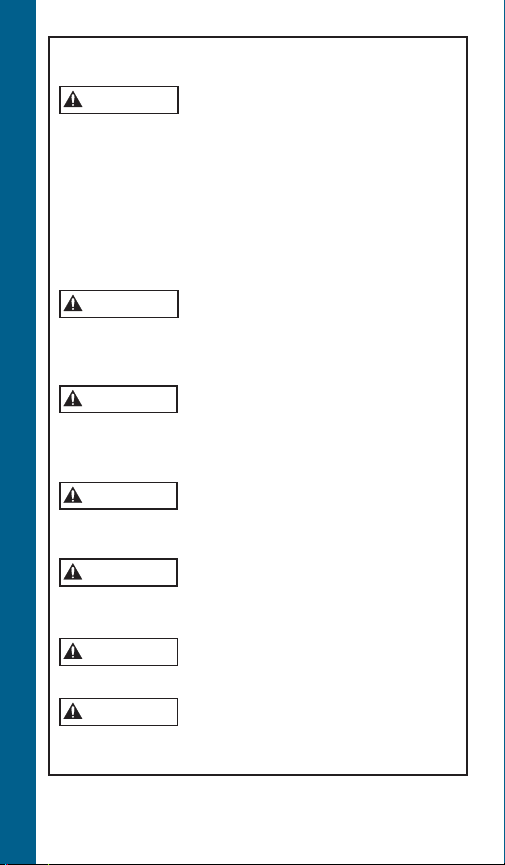
Safety Warnings
DANGER
TO AVOID SERIOUS OR FATAL PERSONAL INJURY OR
MAJOR PROPERTY DAMAGE, READ AND FOLLOW ALL
SAFETY INSTRUCTIONS IN MANUAL AND ON PUMP.
THIS MANUAL IS INTENDED TO ASSIST IN THE
INSTALLATION AND OPERATION OF THIS UNIT AND
MUST BE KEPT WITH THE PUMP.
This is a SAFETY ALERT SYMBOL.
When you see this symbol on the pump
or in the manual, look for one of the
following signal words and be alert to the
potential for personal injury or property
damage.
Warns of hazards that WILL cause
serious personal injury, death or major
property damage.
WARNING
CAUTION
NOTICE: INDICATES SPECIAL INSTRUCTIONS
WHICH ARE VERY IMPORTANT AND
MUST BE FOLLOWED.
THOROUGHLY REVIEW ALL INSTRUCTIONS AND
WARNINGS PRIOR TO PERFORMING ANY WORK
ON THIS PUMP.
MAINTAIN ALL SAFETY DECALS.
Warns of hazards that CAN cause serious
personal injury, death or major property
damage.
Warns of hazards that CAN cause personal injury or property damage.
SAFETY WARNINGS
3
WARNING
WARNING
WARNING
WARNING
WARNING
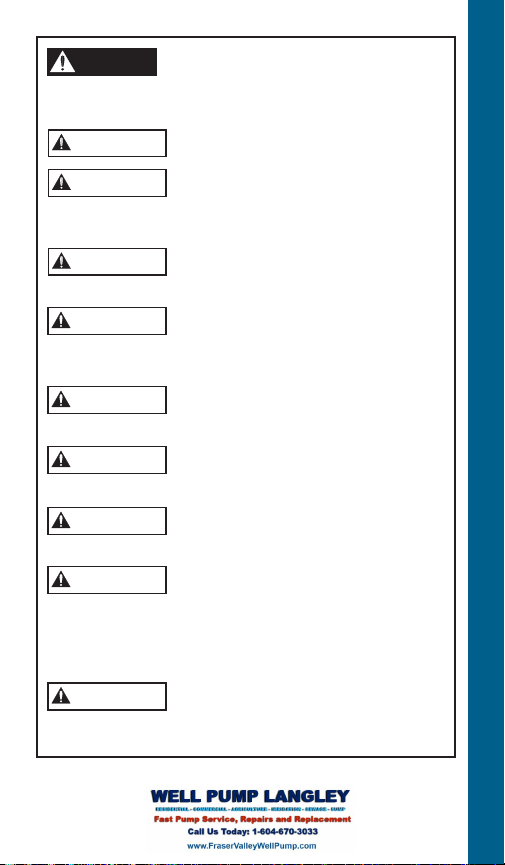
Important notice: Read safety instructions before
WARNING
WARNING
proceeding with any wiring.
All electrical work must be performed by
National Electrical Code (NEC), or the Canadian Electrical Code, as well as all local, state and provincial codes.
Code questions should be directed to your local electrical
inspector. Failure to follow electrical codes and OSHA safety
standards may result in personal injury or equipment damage. Failure to follow manufacturer’s installation instructions
may result in electrical shock, fire hazard, personal injury or
death, damaged equipment, provide unsatisfactory perfor-
SAFETY WARNINGS
mance, and may void manufacturer’s warranty.
hazardous liquids, or where flammable gases exist. Well must
be vented per local codes. See specific pump catalog bulletins
or pump nameplate for all agency Listings.
cal equipment. Many pumps are equipped with automatic
thermal overload protection which may allow an overheated
pump to restart unexpectedly.
maximum pressure rating. This will damage the tank, voids
the warranty and may create a serious hazard.
may create a hazard. See tank warning labels and IOM for
more information.
cal cables can cause shock, burns or death.
be at least as large as the power supply wires. Wires should
be color coded for ease of maintenance and troubleshooting.
a qualified technician. Always follow the
Standard units are not designed for use in
swimming pools, open bodies of water,
Disconnect and lockout electrical power
before installing or servicing any electri-
Never over pressurize the tank, piping or
system to a pressure higher than the tank's
Protect tanks from excessive moisture and
spray as it will cause the tank to rust and
Do not lift, carry or hang pump by the
electrical cables. Damage to the electri-
Use only stranded copper wire to pump/
motor and ground. The ground wire must
4
WARNING
WARNING
WARNING
WARNING
WARNING
WARNING
DANGER
WARNING
Install wire and ground according to
WARNING
WARNING
the Canadian Electrical Code, as well as all local, state and
provincial codes.
Incorrect voltage or phase can cause fire, motor and control
damage, and voids the warranty.
instructions.
location. The junction box must insure dry, safe wiring
connections.
valve operation.
power can cause shock, burns or death.
quick-trip, overload protection.
past the motor for proper motor cooling. The following are
the minimum flows in GPM per well diameter required for
cooling: 1.2 GPM/4", 7 GPM/5", 13 GPM/6", 20 GPM/7",
30 GPM/8" or 50 GPM in a 10" well.
sleeve to create the needed cooling flow or velocity past the
Well Pump Langley for Water Well Pump Service in Langley & Aldergrove.
motor.
the National Electrical Code (NEC), or
Install an all leg disconnect switch where
required by code.
The electrical supply voltage and phase
must match all equipment requirements.
All splices must be waterproof. If using
splice kits follow manufacturer’s
Select the correct type and NEMA grade
junction box for the application and
All motors require a minimum
5' submergence for proper refill check
Failure to permanently ground the pump,
motor and controls before connecting to
All three phase (3Ø) controls for submersible pumps must provide Class 10,
4" motors ≥ 2 HP require a minimum
flow rate of .25 ft/sec. or 7.62 cm/sec.
Pumps ≥ 2 HP installed in large tanks
should be installed in a flow inducer
SAFETY WARNINGS
5
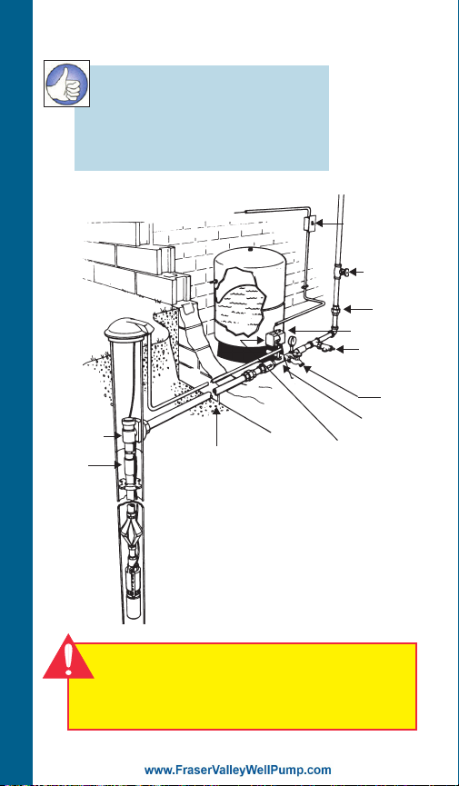
Two-Wire System Illustrated
RULE OF THUMB
1. Use same size or larger
pipe as discharge on pump.
2. Always use a check valve
for every 200 ft. of vertical pipe.
To House Piping
Protected Power Supply
TYPICAL SYSTEM
Pitless
Adapter ➀
Check
Valve ➀
Frost Level
➀ On installations with a pitless adapter
the top check valve should be below
the pitless, not at the tank, as the
discharge line should be pressurized
back to the pitless.
➁ On installations with well seals or well
pits it is allowable to locate the top
check valve near the tank.
Check Valve ➁
Disconnect
Switch
Shut-off
Valve
Union
Pressure
Switch
Pressure
Relief Valve
Drain
Tap
Tank Tee
CAUTION
All electrical equipment must be connected
to supply ground. Follow applicable code
requirements.
6
Motor Cooling, Temperature
and Time Ratings
All 4 inch CentriPro motors may be
operated continuously in water up to
86º F. Optimum service life will be
attained by maintaining a minimum
ow rate past the motor of .25 feet per
second. Use a Flow Sleeve if velocity
is below the .25'/sec, if the well is top
feeding or when the pump is used in a
large body of water or large tank.
Six (6) inch canned design motors from
5 – 40 HP will operate in water up to
95º F (35º C), without any de-rating of
horsepower, with a minimum ow rate of
.5 ft./sec. past the motor. 6" – 50 HP and
all 8" – 10" motors can operate in 77º F
(25º C) water with .5'/sec velocity past
the motor.
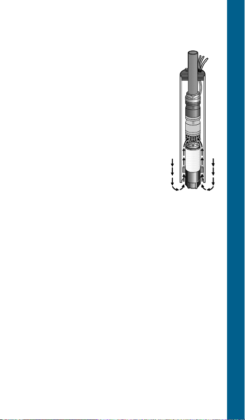
One way to make a ow sleeve is to install a well seal
above the pump discharge and slip a piece of casing
over the pump and afx it to the well seal. Drill three
holes at 120º intervals on the lower section of the casing
and insert (3) screws and nuts through the casing, just
touching the motor. Tighten the nuts out against the
casing. Insure that the screws do not protrude out too
far as you don’t want them catching on well joints.
FLOW SLEEVE
TYPICAL SYSTEM
Pump Cooling and Lubrication
In addition to motor cooling, another reason to
maintain minimum ow rates is pump lubrication. All
manufacturers’, either on curves or in selection charts,
show minimum ows. This insures that rotating pump
parts are properly lubricated to prolong service life and
reduce friction. A dead headed pump will super heat
water very quickly, and hot water has no lubricity.
7
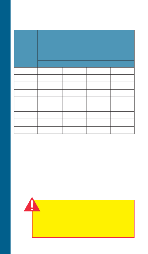
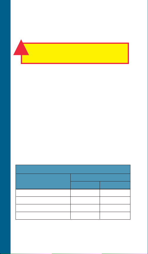
Minimum Flow Rates for
Proper Motor Cooling
3.75" Dia. CP = FE = CP =
Well or 4" CP or 5.5" Dia. 5.38" Dia. 7.52" Dia.
Sleeve FE Motor 6" CP 6" FE 8" CP
Diameter .25'/sec Motor Motor Motor
(inches) .5'/sec. .5'/sec. .5'/sec.
GPM Required
TECHNICAL DATA
4 1.2 – – –
5 7 – – –
6 13 7 9 –
7 20 23 25 –
8 30 41 45 9
10 50 85 90 53
12 80 139 140 107
14 110 198 200 170
16 150 276 280 313
Multiply gpm by .2271 for m3/Hr.
Multiply gpm by 3.785 for l/min.
IMPORTANT
This manual is intended ONLY for use by
professionals familiar with NEC (National
Electric Codes) electrical codes and
hydraulic and safety procedures of pump
installations.
8

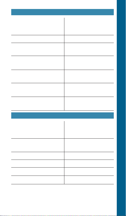
Pump Motor Not Running
Probable Cause
1. Motor thermal protector
Recommended Action
1. Allow motor to cool, ther-
tripped
a. Incorrect control box
b. Incorrect or faulty
electrical connections
a – e. Have a qualied elec-
c. Faulty thermal protector
d. Low voltage
e. Ambient temperature of
f. Pull pump, clean,
control box/starter too
high
f. Pump bound by foreign
g. Conrm adequate unit
matter
g. Inadequate submergence
2. Open circuit breaker or
2. Have a qualied electri-
blown fuse
3. Power source inadequate
3. Check supply or generator
for load
4. Power cable insulation
4 – 5. Have a qualied electri-
damage
5. Faulty power cable splice
TROUBLESHOOTING
mal protector will automatically reset
trician inspect and repair,
as required
adjust set depth
as required
submergence in
pumpage
cian inspect and repair, as
required
capacity
cian inspect and repair, as
required
RULE OF THUMB
Remember, there may be other
system problems caused by
auxiliary controls not covered in
this booklet.
9

Little or No Liquid Delivered by Pump
Probable Cause
1. Faulty or incorrectly installed
check valve
2. Pump air bound
3. Lift too high for pump
TROUBLESHOOTING
4. Pump bound by foreign
matter
5. Pump not fully submerged
6. Well contains excessive
amounts of air or gases
7. Excessive pump wear
Recommended Action
1. Inspect check valve, repair
as required
2. Successively start and
stop pump until ow is
delivered
3. Review unit performance,
check with dealer
4. Pull pump, clean, adjust set
depth as required
5. Check well recovery, lower
pump if possible
6. If successive starts and
stops does not remedy,
well contains excessive air
or gases
7. Pull pump and repair as
required
8. Incorrect motor rotation
– 3Ø only.
10
8. Reverse any two motor
electrical leads
Pump Will Not Start or Run. . .
Probable Cause
1. No power
2. Incorrect voltage
3. Defective pressure switch
4. Loose wire connections
5. Cable insulation damaged
6. Damaged or poor splice
7. Pump bound by sand or
abrasives
Pump Starts Too Frequently. . .
Probable Cause
1. Waterlogged tank
2. Check valve broken or stuck
open
3. Improper switch setting
4. Improper switch placement
5. Leaks in piping
6. Tank too small for pump
Recommended Action
1. Check for tripped circuit
breaker
2. Check with voltmeter
3. Inspect switch points and
wires
4. Check all connections and
splices
5. Perform cable check with
ohmmeter
6. Perform cable check with
ohmmeter
7. Pull pump and repair as
required
Recommended Action
1. Check tank pressure when
empty of water
2. Replace check valve
3. Adjust switch
4. Move switch closer to tank
5. Replace defective pipe
6. Install larger tank
TROUBLESHOOTING
11
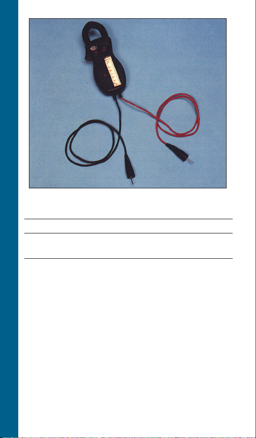
The Amprobe is a multi-range, combination
ammeter and voltmeter.
Voltmeter Scales: 150 Volts 600 Volts
Ammeter Scales: 5 Amps 40 Amps
AMPROBE/OHMMETER INSTRUCTIONS
15 Amps 100 Amps
1. When used as an ammeter, the tongs are
placed around the wire being measured
with the rotary scale on the 100 amp
range. Then rotate the scale back to the
smaller ranges until an exact reading is
indicated.
2. When used as a voltmeter, the two leads are
clipped into the bottom of the instrument
with the rotary scale on the 600 volt range.
If the reading is less than 150 volts, rotate
the scale to the 150 volt range to get a more
exact reading.
12
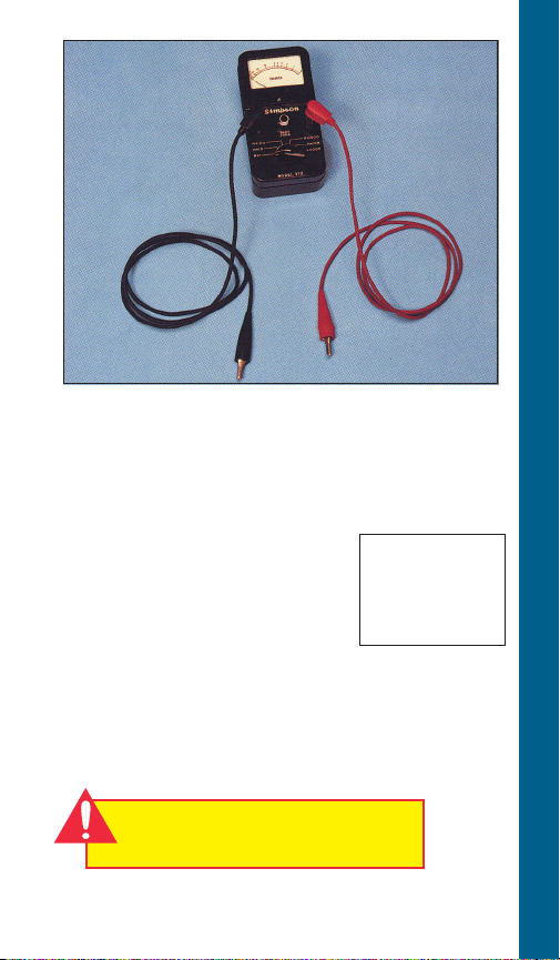
The Ohmmeter is used for measuring the
electrical resistance of a wire circuit. The unit of
measurement is called an Ohm.
1. The knob at the bottom of the Ohmmeter is
adjustable through six ranges:
RX1 = R x 1
RX10 = R x 10
RX
RX
RX
RX
= R x 100
100
= R x 1,000
1000
= R x 10,000
10K
= R x 100,000
100K
If your ohmmeter
is digital readout
type, refer to the
instructions that
came with it.
2. The round center knob is for the purpose of
adjusting the instrument to zero (0) after
clipping the two ohmmeter leads together.
This must be done every time the range
selection is changed.
AMPROBE/OHMMETER INSTRUCTIONS
CAUTION
Use Ohmmeter only with power off.
13
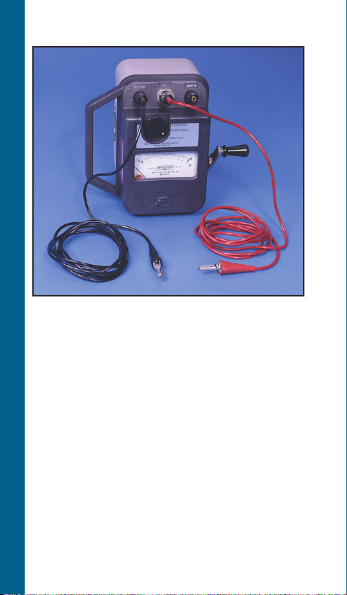
Megger
This instrument is used to measure insulation
MEASURING INSULATION RESISTANCE
resistance to ground. It consists of a crankturned magneto, on the side of the case, and
will give very close readings calibrated directly in ohms. It is cranked at a moderate rate
of speed, approximately 120 rpm, until the
pointer reaches a steady deflection.
1. If the ohm value is normal, the motor
windings are not grounded and the cable
insulation is not damaged.
2. If the ohm value is below normal, either the
windings are grounded or the cable insulation is damaged. Check the cable at the well
seal as the insulation is sometimes damaged
by being pinched.
14
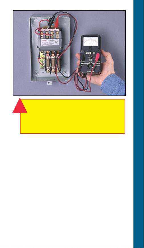
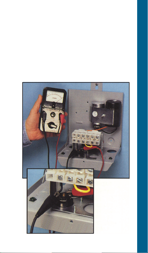
WARNING!
!
Open master breaker and disconnect all
leads from starter to avoid damage to
meter or electric shock hazard. Connect
the ohmmeter leads as shown above.
Coil with Ohmmeter
1. Set R x 1000.
2. Connect leads as shown.
3. Reading: Should register some value,
Approx. 200-1000 ohms.
COIL CHECKOUT
What It Means –
Infinity reading indicates coil is open. Zero
reading indicates coil is shorted. In either case,
the coil should be replaced.
A reading of 200-1000 ohms indicates coil is
ok.
15
Voltage Relay
CONTROL BOXES (CENTRIPRO OR F.E.)
Checking Relay with Ohmmeter
A. Voltage Relay Tests
Step 1, Coil Test
1. Meter setting: R x 1,000.
RELAY CHECKOUT
2. Connections: #2 & #5.
3. Correct meter readings:
For 115 Volt Boxes:
.7 – 1.8 (700 to 1,800 ohms).
For 230 Volt Boxes
4.5 – 7.0 (4,500 to 7,000 ohms).
16

Voltage Relay
CONTROL BOXES (CENTRIPRO OR F.E.)
Step 2, Contact Test
1. Meter setting: R x 1.
2. Connections: #1 and #2.
3. Correct meter reading:
Zero for all models.
B. F.E. Blue Relay - Solid State
1
⁄3 – 1 HP QD Control Boxes
Used from 1994 until present time:
Step 1, Triac Test
1. Meter setting: R x 1,000.
2. Connections: Cap and B terminal.
3. Correct meter reading: Innity for all
models.
Step 2, Coil Test
1. Meter setting: R x 1.
2. Connections: L1 and B.
3. Correct meter reading:
Zero ohms for all models.
RELAY CHECKOUT
17

Checkout Procedure
for Magnetic and Other
Contactors
Contactor Coil Test
(Disconnect lead from one side of coil)
1. Meter setting: R X 100
2. Connections: Coil terminals
3. Correct meter reading: 180 to
1,400 ohms
Contactor Contact Test
CONTACTOR CHECKOUT
1. Meter Setting: R X 1
2. Connections: L1 & T1 or L2 & T2
3. Manually close contacts
4. Correct meter reading: Zero ohms
Additional information on troubleshooting
and replacement parts for 1Ø Control Boxes
is available in the MAID; Motor Application
and Installation Manual. It is also available
online at www.xyleminc.com/brands/
gouldswatertechnology.
18
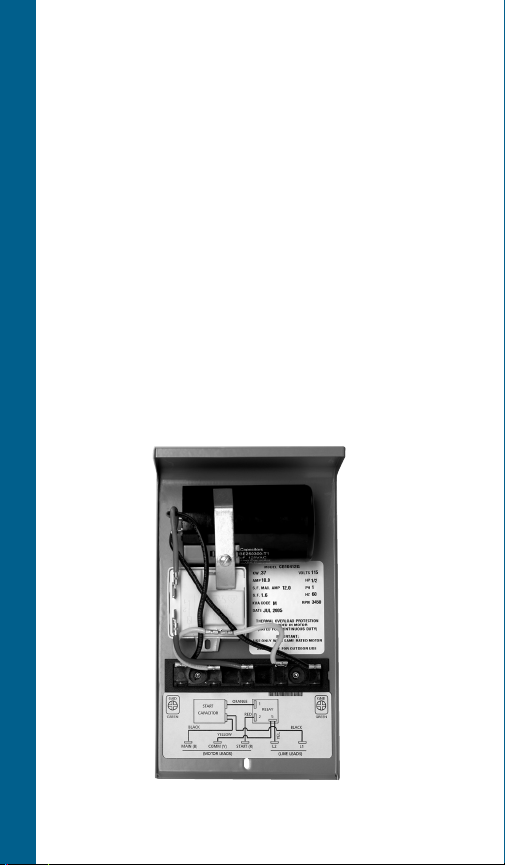
For 1½ HP (and Larger)
Control Box
1. Set Ohmmeter at “R x 1”
2. Connect the Ohmmeter leads to Terminal
#1 and #3 on each Overload Protector.
3. Reading should be not more than 0.5
Ohms maximum on the scale.
CSCR or Mag. Contactor Control Box
OVERLOAD CHECKOUT
19

Capacitor with Ohmmeter
CAPACITOR CHECKOUT
CAUTION
Discharge the capacitor before making
this check. (A screwdriver can be used
to make contact between capacitor’s
posts.)
1. Disconnect leads to capacitor post.
2. Setting: R x 1,000
3. Connect ohmmeter leads to capacitor posts.
4. Reading: Pointer should swing toward zero,
then back toward innity.
20
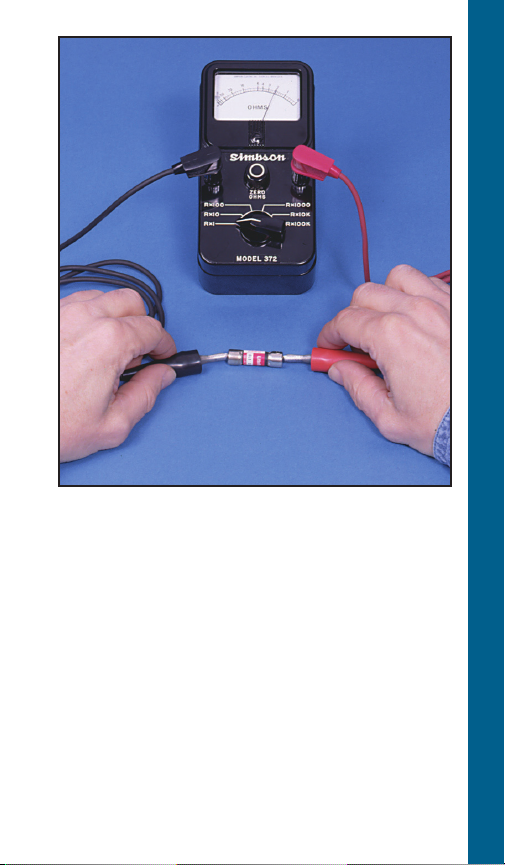
1. Set R x 1.
2. Connect leads as shown.
3. Reading: Should register zero.
What It Means –
Zero reading indicates fuse OK. Infinity (∞)
reading indicates bad fuse.
FUSE CHECKOUT
21
To Check Voltage with “Q.D.”
Type Control Box
1. Remove cover to break all motor
connections.
CAUTION
L1 and L2 are still connected to power.
2. To check VOLTAGE: Use voltmeter on L1
VOLTAGE CHECKOUT
and L2 as shown.
3. When checking voltage, all other major
electrical appliances (that could be in use at
the same time) should be running.
4. If readings are not within the limits (see
chart), call your power supplier.
Voltage Limits
Measured Volts
Nameplate ▼ Min. Max.
115V 1Ø 105 125
208V 1Ø 188 228
230V 1Ø 210 250
22
VOLTAGE CHECKOUT
23
Checking Voltage at Fused
Disconnect and Magnetic
Starter
WARNING!
!
Power is ON during voltage checking.
1. To check voltage: Use voltmeter on L1, L2
and L3 in sequence. Check should be made
at four locations.
Step 1 Checking incoming power supply.
Step 2 Checking fuses.
Step 3 Checking contact points
Step 4 Checking heaters.
2. When checking voltage, all other major
electrical appliances (that could be in use at
VOLTAGE CHECKOUT 3Ø STARTER
the same time) should be running.
3. If incoming power supply readings are not
within the limits (see chart), call your power
supplier.
NOTE: Phase to phase – full line voltage.
Voltage Limits
Name Plate ▼
208V 3Ø 188 228
230V 3Ø 207 253
460V 3Ø 414 506
575V 3Ø 518 632
Measured Volts
Minimum Maximum
Phase to neutral – ½ full line voltage.
(depending on transformer connection)
24
VOLTAGE CHECKOUT
VOLT
6
VOLT
600 -
500 -
400 -
00 -
00 -
00 -
0 -
25
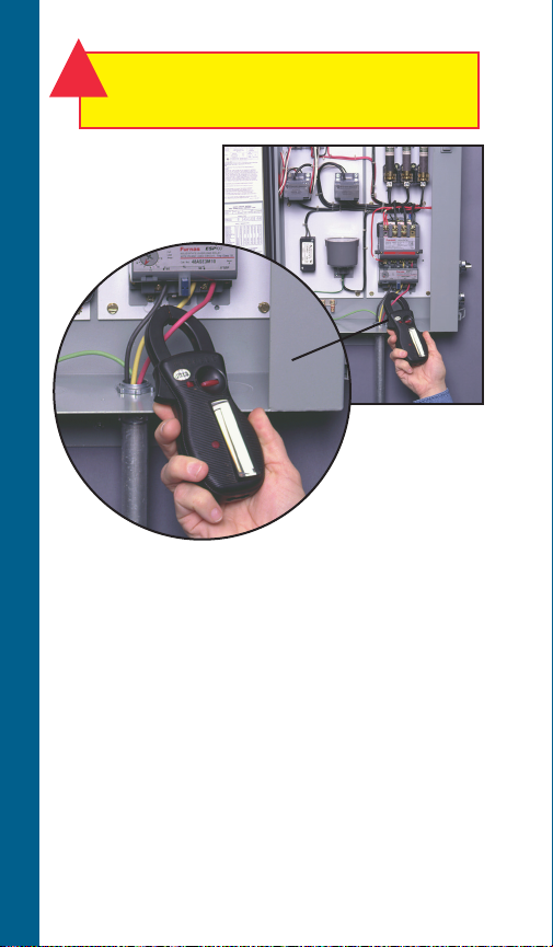
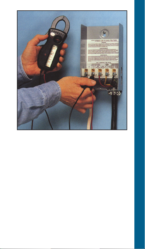
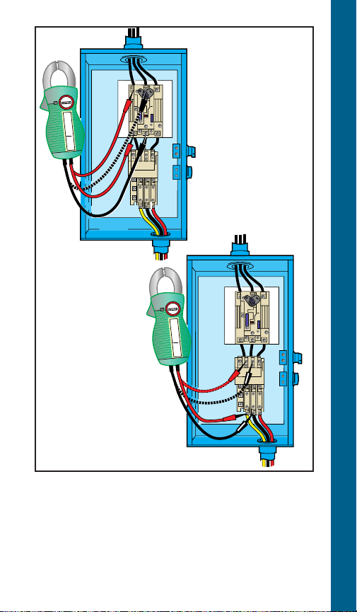
WARNING!
!
Power is ON during current checking.
CURRENT (AMPERAGE) CHECKOUT
Using Amprobe
1. Set scale to highest amp range.
2. Connect amprobe around lead as shown.
3. Rotate scale to proper range and read
value.
4. Compare value with table.
What It Means –
Currents above these values indicate system
problems.
26

Service Factor Amps with QD (½ - 1 HP) or
CSCR (1.5 HP & Larger) Control Boxes ①
4" CP F.E. CP F.E.
1Ø 3-Wire 3-Wire 2-Wire 2-Wire
HP Volts Yel Black Red Yel Black Red Black Black
½ 115 12.6 12.6 0 12.0 12.0 0 9.5 12.0
½ 6.3 6.3 0 6.0 6.0 0 4.7 6.0
¾ 8.3 8.3 0 8.0 8.0 0 6.4 8.0
1 9.7 9.7 0 9.8 9.8 0 9.1 9.8
1½ 230 11.1 11.0 1.3 11.5 11.0 1.3 11.0 13.1
2 12.2 11.7 2.6 13.2 11.9 2.6
3 16.5 13.9 5.6 17.0 12.6 6.0 N/A
5 27.0 22.0 10.0 27.5 19.1 10.8
① Generation I CentriPro data. See pages 37-41 for Generation II
data.
Service Factor Amps with Magnetic Contactor
Control Boxes
6"
1Ø 3-Wire
HP Volts Yel Black Red Yel Black Red
5 27.5 N/A N/A 27.5 17.4 10.5
7.5
10 58.0 N/A N/A 51.0 47.5 8.9
15 85.0 N/A N/A 75.0 62.5 16.9
CentriPro 3-Wire
41.0 N/A N/A 42.1 40.5 5.4
230
Franklin Electric
CURRENT (AMPERAGE) CHECKOUT
27
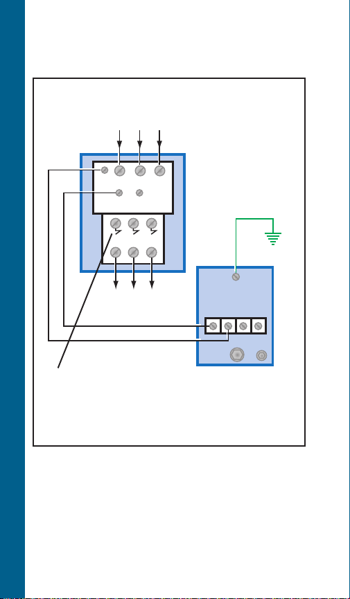
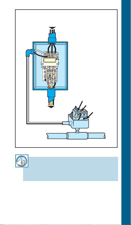
Magnetic Starter and Pressure
Switch
To Fused Disconnect
Or Circuit Breaker 3Ø
3
L
L
1
2
1
L
T1T
2
T
2
3
3 Phase Starter
L
3
Magnetic
Starter
TYPICAL WIRING DIAGRAMS
To Pump Motor
Requires class 10
quick trip “k-heaters”
(overloads), or adjustable class 10
overloads such as ESP100, ESP 200
NOTE:
Check to be sure proper selection of
pressure switch matched to system
voltage has been made... refer to
catalog data.
Check that starter has ground.
Pressure Switch
Line
Load
Ground
Line
Load
28
To Fused Disconnect
Or Circuit Breaker
3Ø
To Pump Motor
Magnetic
Starter
Line
Load
Ground
Pressure
TYPICAL WIRING DIAGRAMS
Switch
RULE OF THUMB
Check that starter has ground.
29

Magnetic Starter, Pressure
Switch and Liquid Level
Control
To Fused Disconnect
Or Circuit Breaker 3Ø
Magnetic
L
T
2
3
L
Load
3
Ground
Starter
Input Power
(As Required
By Level Control)
1
2
Level
Control
5
Lower Upper
Electrode
3
L
L
1
2
1
3 Phase Starter
T1T
2
TYPICAL WIRING DIAGRAMS
To Pump Motor
Line
Load
Line
Pressure Switch
NOTE:
Check to be sure proper selection of
pressure switch matched to system voltage
has been made... refer to catalog data.
Check that starter has ground.
36
97
Ground
30
 Loading...