

Mini F 1-2 Pump Cold Water
Booster Sets Fixed Speed
Operating and Maintenance Instructions
Declaration of conformity
Lowara pumps UK declare that the Mini F Booster set conforms to the requirements of the Machinery Safety
Directive 98/37/EEC.
Conforming to the UK Health & Safety Requirements S.I. 1992 No 3073 S.I. 1994 No 2063
Water supply (Water fittings) regulations 1999
Simple pressure vessel directive 87/404/EEC
Signed: Position: Engineering manager Date: 27-02-2012 Revision
Clive Willmott
Introduction
This leaflet contains information to enable the safe installation and operation of the products mentioned.
The following instructions must be read and understood by all persons responsible for the installation,
operation and maintenance of this product.
Warning Symbols
Safety instructions where noncompliance would affect safety.
Safety instruction where electrical hazard is involved.
Safety instruction where noncompliance could cause damage to the equipment.
Instruction for safe us
Noise Emission
This equipment operates at a noise level lower than 70dBA.
Operating limits
This product has been designed for boosting cold water in potable water installations to the
operating conditions shown.
This product should not be installed until this leaflet has been studied carefully and understood.
Handling, transportation and installation of this equipment should only take place with the proper
use of lifting equipment. This product must be stored in a frost-free dry environment.
Fluid temperature 0°C to 40°C
Ambient temperature 0°C to 40°C
Operating pressure Max 5Bar.
Protection class. Motor & Electrical panel IP55
1
Installation
The cold Water booster set is despatched mounted on a wooden pallet and covered in a protective film, it is
have damage it must be reported immediately and should not be installed. The unit should be
sited in a ventilated, dry frost free position also ensuring adequate room for general maintenance and
service. The set should be fixed in position directly to the floor, if vibration separation is required then cork
mats should be used supplied by others.
The water tank is constructed to have a weir slot as required by the water bylaws to prevent back flow
contamination, if the inlet ball valve suffered a catastrophic failure the overflow may not be able to keep up
with the inflow in which case excess water will be ejected through the weir slot and onto the plant room floor,
if this is not acceptable then consideration should be given to fitting the booster set onto a try with overflow
to drain.
Never run pumps dry
Ensure the pumps are filled with water before switching the power on.
Electrical connections
The electrical connections must be carried out by a competent electrician in accordance with local
regulations.
on the set duty plate.
Never operate this product with isolation panels removed or the control panel door in the open position.
It is essential that this equipment is earthed to the building earth system.
All metal parts must be earth bonded directly to the building earth system.
recommended that the unit be retained in the protective packaging until the product is to be
installed. The unit will arrive pre-packaged and wired ready for installation. This product has
been fully run tested at our works under simulated site conditions. The unit should be thoroughly
checked for physical damage that may have been caused during transit. If the unit is found to
The cable used for the incoming supply must be of adequate size to carry the motor full load
current of all pumps as they are able to operate at the same time. Motor ratings are shown on
the set duty plate. All non power cable should be limited to 1.5mm².
All connections must be made using the appropriate wiring drawings for the equipment being
installed; with particular attention being paid to the supply voltages. The supply voltage is shown
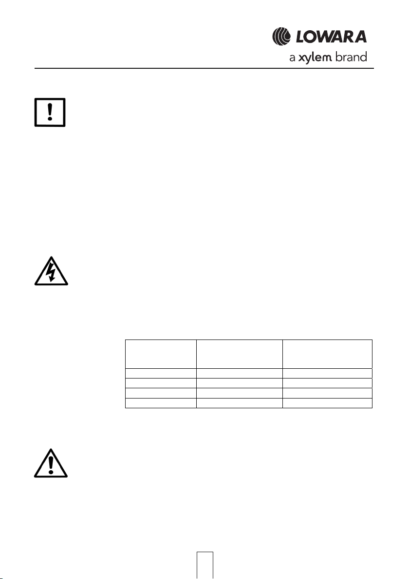
Electrical data HM sets
Nominal power
(KW) 1 pump
GMS10 single phase
Absorbed current(A)
1 x 230V
GMS20 single phase
Absorbed current(A)
1 x 230V
0.45 2.77 5.54
0.55 3.76 7.52
0.75 5.74 11.48
0.9 6.49 13.0
Water supply connections
Connect the incoming water supply to the break tank ball valve. The outlet of the tank will already be connected
It is the responsibility of the installer to ensure that the overflow is able to keep up with the incoming water
volume, if this is not the case then a pressure reducing valve should be fitted to reduce the incoming mains
water volume.
to the booster set suction manifold. The tank will include a class AB air gap (Category 5 protection)
the tank will also include a low level float switch connected to the booster set to protect against dry
running. Connect the 22mm warning pipe to a position where a discharge will cause a nuisance
and be remedied. Connect the overflow pipe to drain. When the tank has been filled check the
water level and adjust ball valve as necessary.
Ensure the tank is thoroughly flushed through before the set is put on line.
2

Discharge pipe work
On two pump sets the discharge pipe work can be connected to either end of the booster set, ensure the
blanking cap is fitted to the end not used. A flexible connector fitted between the booster discharge manifold
and the system connection pipe will help prevent the transmission of noise/vibration. On single pump units
connect to the port provided. An isolation valve should be provided between the booster discharge line and
the system to aid maintenance. The discharge pipe work should be sized to achieve a maximum velocity of
approximately 2.5m/s.
Pressure vessels
The booster set is fitted with 1 or 2 x 24lt vessels which is the minimum that should be used with fixed speed
pump sets. Larger vessel can be added if required. If stand alone vessels are added they should have an
isolation valve and drain cock fitted to allow the vessel to be isolated from the system and drained to check
the pre-charge pressure.
The vessel pre-charge should be set to approximately 0.2 bar below the pump stating pressure.
Pressure switch setting details
The booster set will be fitted with 1 pressure switch for each pump.
Pump operation is controlled by pressure switches, one for each pump. The unit will normally be
supplied with the pressure switches set to match the pumps fitted.
If pressure switch settings need altering they should be adjusted as follows. Read in conjunction
with fig A
P1s = pump 1 stop pressure which is normally set to 0.5
bar below Pmax (pump closed valve head).
P2s = pump 2 stop pressure which is normally set to 1
bar below Pmax when fitted.
P1 = pump 1 differential pressure which is normally set
at 1 bar, this will start pump one, 1 bar below P1s.
P2 = pump 2 differential pressure which is normally set
at1 bar, this will start pump two 1 bar below P2s when
fitted.
Fig A
Pump 1
Commissioning
With the main power isolated check:
1. The break tank feeding the set is filled with water and the ball valve is set to the correct height.
2. The set/system vessels have been charged with Nitrogen to the correct pressure (set point -0.2 bar).
3. Open suction line isolation valve.
9. Open discharge valve.
10. Ensure all vessel valves are open.
11. Switch the main power supply on.
12. allow water to flow and clear air through the system
13. close discharge valve and check pressure reading on pressure gauge
14. The system set point should already be set but to change refer to fig A above.
See GXS O&M for more in depth pump details.
4. Open suction and discharge pump isolation valves.
5. Close main discharge isolation valve.
6. Open the pump vents at the top of each pump.
7. Allow all air to escape until water flows freely.
8. Close pump vent valves.
3

Operation
The booster set is designed to boost the system pressure and maintain sufficient pressure to overcome the
static height and friction losses in the pipe work and provide each outlet with sufficient flow at the required
pressure.
When a demand is placed on the system, water will be supplied from any vessels that are fitted to the
system, once this supply is depleted the system pressure will start to fall, when the pressure falls to the
system set point the first pump will start and raise the pressure to maintain the set point, if demand
increases and the first pump is not able to cope the pressure will continue to fall to the second pump cut in
pressure (if fitted) The second pump will start and assist the first pump.
When demand decreases the last pump to be called in will be stopped, if demand continues to decrease
the next pump will be stopped. On two pump sets minimum run timers are fitted so once a pump has been
signalled to start it will run for a minimum of 90 seconds (default setting) even if the demand has cessed.
The next time the pressure falls the pumps will have been rotated so the opposite pump will be the first to
operate.
If a low level in the break tank occurs all pumps will be stopped until the water supply has been reinstated,
the pumps will then be automatically released to resume normal operation.
Because the pumps can run on through the timer circuit it is possible that the system pressure can sit at the
closed valve pressure of the pump.
Volt Free Contacts
Volt free contacts are not available on single pump units or on twin GXS sets.
Fig 3
Remote inhibit
Remote inhibit facilities are not available.
Alarm indicators
LEDs are provided to indicate:
Single pump sets. Pump run, pump tripped and low water level Fig 3
Twin pump sets. Pump run each pump, Power on and low water level Fig 1 & 2.
Panel
Single pump
Fig 2. Gives details of indications and switches for the GXS20 twin pump control panel.
Fig 2
4
Pump
running
LOWARA
Low
fault
level
Off
Auto
`Hand

Caution
This booster set is an automatic machine; the pumps may start up automatically without
prior warning.
The set contains pressurised water; reduce the pressure to zero before servicing.
Maintenance
5. Check that the earth connections are tight and making good contact.
6. Check that the gas pre charge is at the correct pressure, this should be done by isolating the vessel
from the system and draining water out of the vessel via the isolation valve drain point.
Once the water has been discharged, a tyre gauge can be connected to the pre charge valve to display the
vessel pre charge pressure. Recharge as necessary with Nitrogen or dry air.
Any other expansion vessels connected to the system can be checked in the same manner.
Clean any filters that may be connected to suction/discharge lines and ensure the mesh is in good condition.
General fault finding guide
Routine check (6 monthly intervals)
1. Check all pumps produce the correct pressure.
2. Check that the pump operates without undue noise or vibration.
3. Check the break tank is clean and that the correct water level has been maintained.
4. Check that all screws are tight on electrical components.
Fault Possible Cause Remedy
Power supply failure
Pump fails to start
Pump fails to stop
Pump switches on and off
quickly
Pump runs but will not make
pressure
Pump overheating Pump partially seized
Pump set frequently
starting. (pressure falls to
cut in point)
Break tank overflowing Leaking ball valve
Pump leaks water
Control panel fuse blown
MCB tripped
Low water level
Set point set too high
System pressure low due to
large leak
Air in system
Vessel pre-charge incorrect
Pump air locked
Non-return valve jammed
Passing too much water
Newly installed system with
large amount of air in pipe work
Leaks in system pipe work
Vessel pre-charge incorrect
Non-return valve letting by
Defective mechanical seal
Undue mechanical stress on
pump
Reinstate incoming power supply
Replace power supply fuse
Reset MCB
Reinstate water supply
Lower set point
Switch unit off until leak is repaired
Purge air from pumps and pipework
Check vessel pre-charge and Charge as
necessary with Nitrogen or dry air
Open pump bleed screw and vent pump
Clean/replace valve
Check system for leaks
Remove pump and check for foreign
objects
Bleed system to remove air
Repair leaks
Isolate vessel and pre-charge with
Nitrogen as appropriate
Replace ball valve seal
Replace/clean non-return valve
Replace seal
Support the pipe work
5

Disposal
Disposal of this product should be carried out in accordance of local codes and regulation pertaining to the
disposal of waste, including packaging materials.
Booster set details
Model type
Order Code
Pump type
Serial number
Installation date
System set point
Booster set notes
Lowara UK Limited
Millwey Rise Industrial Estate, Axminster, Devon EX13 5HU - UK
Tel: 01297 630230 Fax: 01297 630270
e-mail: lowaraukenquiries@xyleminc.com
http://www.lowara.co.uk http://completewatersystems.com
Lowara is a trademark of Xylem Inc. or one of its subsidiaries. © 2011 Xylem, Inc.
Lowara reserve the right to make modifications without prior notice.
cod. UKLIT0088 P05/12
6
 Loading...