

FDO
Operating manual
®
925
ba75898defs01 04/2010
Optical D.O. sensor

FDO®925
Note
The latest version of the present operating manual can be found on the
Internet under www.WTW.com.
18
Copyright © Weilheim 2010, WTW GmbH
Reprinting - even as excerpts - is only allowed with the explicit written
authorization of WTW GmbH, Weilheim.
Printed in Germany.
ba75898S01 04/2010

FDO®925 Contents
Contents
1 Overview . . . . . . . . . . . . . . . . . . . . . . . . . . . . . . . . . . . . . . 21
1.1 Structure and function . . . . . . . . . . . . . . . . . . . . . . . . . . . 21
1.2 Recommended fields of application . . . . . . . . . . . . . . . . 22
2 Measuring / Operation . . . . . . . . . . . . . . . . . . . . . . . . . . . 23
2.1 General information on the handling of the sensor cap . 23
2.2 Commissioning . . . . . . . . . . . . . . . . . . . . . . . . . . . . . . . . 23
2.3 Measuring . . . . . . . . . . . . . . . . . . . . . . . . . . . . . . . . . . . . 23
2.4 Function check and user calibration . . . . . . . . . . . . . . . . 24
2.5 Storage . . . . . . . . . . . . . . . . . . . . . . . . . . . . . . . . . . . . . . 24
3 Maintenance, cleaning, replacement . . . . . . . . . . . . . . . . 25
3.1 General maintenance instructions . . . . . . . . . . . . . . . . . . 25
3.2 Exchanging the sensor cap . . . . . . . . . . . . . . . . . . . . . . . 26
3.3 Cleaning the sensor . . . . . . . . . . . . . . . . . . . . . . . . . . . . 27
3.4 Checking the zero point of the sensor . . . . . . . . . . . . . . . 28
4 What to do if... . . . . . . . . . . . . . . . . . . . . . . . . . . . . . . . . . 29
5 Technical data . . . . . . . . . . . . . . . . . . . . . . . . . . . . . . . . . 30
6 Wear parts and accessories . . . . . . . . . . . . . . . . . . . . . . . 32
ba75898S01 04/2010
19

Contents FDO®925
20
ba75898S01 04/2010
FDO®925 Overview
12
5
7
3106984
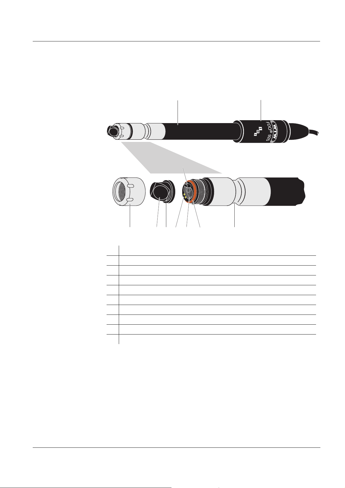
1 Overview
1.1 Structure and function
Structure
Sensor cap with
memory chip
Intelligent mem-
brane (IQMC tech-
nology)
1 Shaft
2 Connection head
3 Fixing ring
4 Sensor membrane
5 SC-FDO
®
925 sensor cap with memory chip
6 Gold-plated contacts for the memory chip of the sensor cap
7 Locking device
8 Measurement window
9 O-ring
10 Thermistor enclosure with temperature sensor
A memory chip is integrated in the sensor cap. The following data are stored
on the memory chip:
z Type designation of the sensor cap
z Series number
z Data of the factory calibration or user calibration
For each membrane, the individual calibration values are determined by a
factory calibration process and stored to the memory chip of the sensor cap,
ensuring maximum accuracy over the whole lifetime of the sensor.
ba75898s01 04/2010
21

Overview FDO®925
Automatic sensor
recognition
The data of the sensor and sensor cap is recalled by the meter when the
sensor is connected and is used for measurement and for measured value
documentation. The calibration data are stored in the sensor cap. Thus, the
calibration is automatically retained if the sensor or meter are exchanged.
The digital transmission technique guarantees the failure-free communication with the meter even with long connection cables.
Firmware update You can update the firmware of sensor via your meter.
Detailed information about firmware update is given in the operating manual
of your meter.
The latest version of the operating manual of your meter and the firmware
update file can be found on the Internet under www.WTW.com.
1.2 Recommended fields of application
Recommended
fields of applica-
tion
z On site measurements in rivers, lakes and wastewater
z Applications in water laboratories
z BOD measurements
22
ba75898s01 04/2010

FDO®925 Measuring / Operation
2 Measuring / Operation
2.1 General information on the handling of the sensor cap
Despite its exterior robustness, the sensor is a high precision optical instrument. Therefore, you should take the following precautions when dealing with
the FDO
z Please do not touch the sensor membrane with your fingers
z Avoid any great mechanical stress of the sensor membrane (pressure,
2.2 Commissioning
Scope of delivery z D.O. sensor FDO®925 with sensor cap
z Check and storage vessel, FDO
z Operating manual
®
925:
scratches).
®
Check
Preparing the sen-
sor for measure-
ment
Minimum immer-
sion depth
Indicent flow The FDO
Connect the sensor to the measuring instrument. The sensor is immediately
ready to measure.
2.3 Measuring
Observe the required minimum immersion depth (see chapter 5 TECHNICAL
DATA).
®
925 D.O. sensor enables precise measurements without any
incident flow.
However, an incident flow of the sensor membrane improves the responding
behavior of the sensor (see chapter 5 T
be provided in different ways, e. g.:
z The flow of the water to be measured is sufficient (aeration tank, water
pipe, stream)
z Slowly pull the sensor through the water by hand (lake, container), or
z Use a flow aid such as a magnetic stirrer with stirring device (see
chapter 6 W
EAR PARTS AND ACCESSORIES)
ECHNICAL DATA). The incident flow can
ba75898s01 04/2010
23

Measuring / Operation FDO®925
12
2.4 Function check and user calibration
Factory calibration The FDO®925 is factory calibrated. In the recommended application (see
page 22), the measuring characteristics of the sensor cap remain stable for
the specified service life. Thus, a user calibration is not usually required.
When does a func-
tion check or user
calibration make
sense?
Check or calibra-
tion medium
A function check or user calibration can be useful in the following special
cases:
z If the measured values appear to be implausible and it is assumed that the
service life of the sensor cap is over
z Routinely within the framework of the company quality assurance.
The check and user calibration take place in water vapor-saturated air. The
suitable conditions are easily provided with the aid of the check and calibration vessel, FDO
®
Check. For this purpose, moisten the sponge inside the
vessel. Then insert the sensor in the vessel as far as it will go. The sensor
membrane must be clean and dry for this.
Moisten the sponge:
z Remove the cap (1).
z Take out the sponge (2), wet it, then slightly squeeze it out.
z Insert the sponge again and close the calibration and storage vessel with
the lid.
After inserting the sensor, wait for the temperatures of the sensor and
calibration vessel to adjust.
Note
The steps of the check or user calibration are described in detail in the operating manual of the meter.
2.5 Storage
Always store the sensor in the check and storage vessel (FDO®Check) at a
temperature in the range 0 ... 50 °C (32 ... 122 °F).
24
ba75898s01 04/2010

FDO®925 Maintenance, cleaning, replacement
3 Maintenance, cleaning, replacement
3.1 General maintenance instructions
Handling of the
sensor cap
Despite its exterior robustness, the sensor is an optical high precision instrument. Therefore, special care should be taken when doing any maintenance
or cleaning work:
z Dirt and moisture under the sensor cap can affect the functioning and
shorten the service life of the sensor cap. Therefore, make sure the working environment is clean and dry prior to removing the sensor cap.
z Please do not touch the outer sensor membrane with your fingers. Touch
the sensor cap at the sides only (arrows in figure on the left).
z Avoid any great mechanical stress of the sensor membrane (pressure,
scratches).
z Exposure to light, particularly daylight, of the interior of the sensor cap will,
by-and-by affect the measurement characteristics and shorten the service
life of the sensor cap. Therefore, the interior of the sensor cap should not
be exposed to direct sunlight. Avoid any exposure to light that exceeds the
extent required for necessary maintenance and cleaning activities. Store
dismantled sensor caps in a light-protected environment only.
ba75898s01 04/2010
25

Maintenance, cleaning, replacement FDO®925
3.2 Exchanging the sensor cap
Note
Before removing the sensor cap, observe the general maintenance instructions in section 3.1.
To exchange the sensor cap, proceed as follows:
Removing the sen-
sor cap
Mounting the sen-
sor cap
1 Pull the sensor out of the sample.
2 Clean the outside of the sensor (see section 3.3.1).
3 Unscrew the fixing ring from the sensor by hand.
4 Thoroughly clean and dry the sensor head once again.
5 Grasp the sensor cap on the sides (arrows in figure on the left) and
remove it by pulling it away from the sensor in a straight
upward
direction.
Caution:
Do not push any tools or other sharp objects between the sealing surfaces. This would damage the sealing surfaces and sealing ring.
6 Check the front surface of the sensor for absolute cleanness and
clean it if necessary (see section 3.3.2).
7 Thoroughly clean the thread of the fixing ring.
26
8 Check the sealing ring for intactness and correct position.
The sealing ring has to be replaced if it is damaged.
9 Aim the sensor head upwards and place the new sensor cap on the
sensor. The locking device on the sensor head must be inserted into
the receptacle on the inside of the sensor cap (see figure on the left).
10 Put the fixing ring on the sensor head and screw it tight by hand as
far as it will go. A gap of approx. 0.8 mm remains between the fixing
ring and sensor.
The sensor is immediately ready to measure.
ba75898s01 04/2010

FDO®925 Maintenance, cleaning, replacement
3.3 Cleaning the sensor
3.3.1 Exterior cleaning
Dirt on the sensor can affect the measuring characteristics. Biological deposits for example, consume oxygen and can, when occurring on the sensor
membrane, impair the responding behavior and cause values that are too
low. Therefore, we recommend regular visual inspections and exterior cleaning as necessary.
Pay attention to the following points for cleaning:
z First, thoroughly rinse the sensor with tapwater to remove loosely adher-
ing dirt.
z Rough dirt on the sensor shaft can be brushed off with a soft brush. Atten-
tion: Do not use the brush in the area of the sensor membrane. Risk of
damage!
z The sensor cap including the sensor membrane should be wiped with a
soft and moist microfiber cloth.
z In the case of persisting dirt you can add some household washing-up liq-
uid to the tapwater. Attention:
Never use any alcohol for cleaning!
3.3.2 Interior cleaning of sensor cap and sensor head
If moisture or dirt have penetrated under the sensor cap, e.g. because the
sensor cap is damaged, you can make the sensor ready for operation again
as follows:
CAUTION
Only use nonabrasive, alcohol-free detergents, as otherwise the optical
surfaces could be damaged.
1 Remove the sensor cap (see section 3.2).
2 Clean the sensor head and sensor cap:
– Rinse all inner surfaces with tapwater
– Remove contamination containing fat and oil with warm water and
household washing-up liquid
– Then rinse all inner surfaces with deionized water
ba75898s01 04/2010
3 Pat dry all surfaces with a clean, lint free cloth.
4 Allow the sensor and sensor cap to dry completely at a dry location
so moisture can evaporate even from corners difficult to access.
When doing, so protect the inside of the sensor cap from light.
5 Put the sensor cap on (see section 3.2).
27

Maintenance, cleaning, replacement FDO®925
Note
If the sensor cap is visibly damaged it has to be replaced.
3.4 Checking the zero point of the sensor
There are two methods to check the zero point of the sensor:
z Measurement in a nitrogen atmosphere (recommended method)
z Measurement in a sodium sulfite solution according to DIN EN 25814/
ISO 5814.
Test criterion The sensor is OK if the measuring instrument displays < 0.5 % D.O.
saturation after 15 minutes.
28
ba75898s01 04/2010

FDO®925 What to do if...
4 What to do if...
Error symptom Cause Remedy
No temperature value or
D.O. value
Measured value too
high or too low
or
error message,
Error
Incorrect temperature
display
– No connection between meter
and D.O. sensor
– Cable defective – Return the D.O. sensor
– Coating on sensor cap – Clean the outside of the sensor
– Membrane damaged – Exchange the sensor cap
– Service life of the sensor cap
over
– Dirt inside the sensor cap and
sensor head
– Fixing ring not properly tightened
– Sensor cap untight or defective
– The temperature sensor is not
immersed deep enough in the
measuring solution
– Establish connection between
meter and D.O. sensor
(see section 3.3.1)
– Check the sensor
– Replace the sensor cap as
necessary (see section 3.2)
– Dismantle the sensor cap
– Clean the insides of the sensor
cap and sensor head (see
section 3.3.2)
– Mount the sensor cap correctly
and tighten the fixing ring as far
as it will go (see section 3.2)
– Replace a defective sensor cap
as necessary
– Observe the minimum immersion
depth
Error message,
no cap
– Temperature sensor defective – Return the D.O. sensor
– No sensor cap put on – Clean the sensor head and
sensor cap
– Sensor cap not recognized – Return the D.O. sensor
– Sensor cap defective – Replace the sensor cap
ba75898s01 04/2010
29

Technical data FDO®925
145.0
201.5
15.3
21.7
5 Technical data
General features Measuring principle Optical measurement based on photolumi-
nescence.
Temperature sensor Integrated NTC 30 (30 k:at 25 °C / 77 °F)
Dimensions
(in mm)
Weight 180 g (with 3 m cable)
Materials Shaft POM
Connection head POM
Sensor cap PVC, silicone and PMMA
Sensor head POM, PV and PMMA
Sensor head - sensor cap
Brass, gold-plated
contacts
Thermistor housing VA steel 1.4571
Fixing ring VA steel 1.4571
Seals FPM (Viton)
Connection cable Lengths 1,5 / 3 / 6 / 25 m
Diameter 4.3 mm
Smallest allowed
bend radius
Fixed installation: 20 mm
Flexible use: 60 mm
Plug type Socket, 4 pins
Pressure
resistance
Sensor with connection cable
IP 68 (2.5 x 10
5
Cable plug IP 67 (when plugged in)
Pa or 2.5 bar)
30
®
The FDO
925 meets the requirements according to article 3(3) of the
97/23/EC directive ("Pressure equipment directive").
ba75898s01 04/2010

FDO®925 Technical data
Measurement
conditions
Measuring ranges at 20 °C
(68 °F)
Temperature range 0 ... 50 °C (32 ... 122 °F)
Max. admissible overpressure
Immersion depth min. 6 cm
Operating position any
Approach flow not required
Storage conditions Recommended storing
method
Storage temperature 0 ... 50 °C (32 ... 122 °F)
Characteristic data
on delivery
Zero signal < 0.1 % of the saturation value
Response time at 20 °C
(68 °F) in stirred solution
Response time of temperature measurement
0 ... 20 mg/l D.O.
0 ... 200 % D.O
saturation
.
0 ... 400 mbar D.O. partial pressure
2.5 x 10
5
Pa (2.5 bar)
max. 25 m (depending on the cable length)
in the check and storage vessel,
®
FDO
t
t
t
t
Check
(90% of the final value display after) < 30s
90
(95% of the final value display after) < 45s
95
(99% of the final value display after) < 60s
99
(99% of the final value display after) < 60s
99
Precision of temperature
measurement
Working life of the sensor
cap
± 0.2 K
Min. 1 year with authorized use
ba75898s01 04/2010
31

Wear parts and accessories FDO®925
6 Wear parts and accessories
Wear parts and
maintenance
Description Model Order no.
Replacement sensor cap SC-FDO
®
925 201 310
equipment
Accessories Description Model Order no.
Calibration and storage vessel FDO
®
Check 201 311
Magnetic stirrer Oxi-Stirrer 300 203 810
Stirring accessory - provides a constant, de-
RZ 300 203 824
fined flow to the sensor, in conjunction with
the Oxi-Stirrer 300. For installation on the
sensor, the ADA FDO/RZ adapter is required.
Adapter for RZ 300 stirring accessory ADA FDO
Funnel set - for BOD measurements in Win-
TS 19 205 710
®
/RZ 201 312
kler bottles
Karlsruhe bottle - suitable for BOD measure-
KF 12 205 700
ment
Fixing ring, recommended for measure-
FR 19 205 712
ments in Karlsruhe bottles
Flow-through accessory - for pressure-free
D 201 203 730
D.O. measurement with flow-through quantities from 25 to 65 ml/min.
Protective armoring (synthetic material) A 925/K 903 836
Protective armoring (stainless steel) A 925/S 903 837
Note
For further accessories, refer to the WTW catalog or the Internet.
32
ba75898s01 04/2010
 Loading...