

Page 1
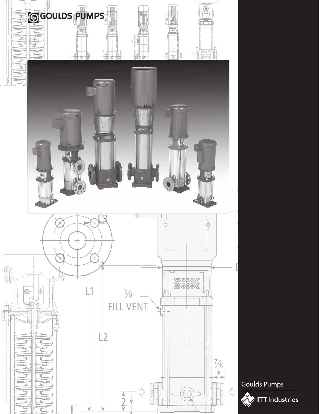
D1
D2
L3
L1
L2
2
3
⁄
8
FILL VENT
3
⁄
8
2 HOLES
M1
315⁄16
57⁄
8
1
⁄2
4 HOLES
CAPACITOR
COVER ON
SINGLE PHASE
ONLY
7
⁄
8
G&L
Series
SSV
TECHNICAL
MANUAL
SSV Series
Vertical
Multi-Stage
Pumps
300 LB. FLANGE
Page 2

Contents
Coverage Curves . . . . . . . . . . . . . . . . . . . . . . . . . . . . . . . . . . . . . . . . . . � 1
General Market Specifications . . . . . . . . . . . . . . . . . . . . . . . . . . . . . . . . . � 2
Characteristics of 1, 2, 3 and 4SV Series . . . . . . . . . . . . . . . . . . . . . . . . . � 3
Characteristics of 33, 46, 66 and 92SV Series . . . . . . . . . . . . . . . . . . . . . � 3
General Characteristics . . . . . . . . . . . . . . . . . . . . . . . . . . . . . . . . . . . . . . � 4
Typical Applications of SV Pumps . . . . . . . . . . . . . . . . . . . . . . . . . . . . . . � 5
SSV Nomenclature . . . . . . . . . . . . . . . . . . . . . . . . . . . . . . . . . . . . . . . .� 6-7
1, 2, 3 and 4SV Series Pump Cross Section and Main Components. . . . .� 8-9
33, 46, 66 and 92SV Series Pump Cross Section and Main Components. . . . . . . . . . . . . . . . . . . . . . . . . . . . . . . . . . . . . . . . . . . . . . . . . . . . . . . . . . . . . . .10-11
SV Mechanical Seals . . . . . . . . . . . . . . . . . . . . . . . . . . . . . . . . . . . . . . . � 12
Maximum Allowable Working Pressure Charts. . . . . . . . . . . . . . . . . . . . � 13
Motor Data . . . . . . . . . . . . . . . . . . . . . . . . . . . . . . . . . . . . . . . . . . .� 14-17
3500 RPM Curves, Dimensions and Weights . . . . . . . . . . . . . . . . . . .� 18-33
2900 RPM Curves, Dimensions and Weights . . . . . . . . . . . . . . . . . . .� 34-49
Round Counterflanges . . . . . . . . . . . . . . . . . . . . . . . . . . . . . . . . . . . . . � 50
Victaulic Accessories . . . . . . . . . . . . . . . . . . . . . . . . . . . . . . . . . . . . . . . � 50
Horizontal Mounting Options . . . . . . . . . . . . . . . . . . . . . . . . . . . . . .� 51-52
Table of Hydraulic Performances at 3500 RPM . . . . . . . . . . . . . . . . . .� 53-56
Table of Hydraulic Performances at 1750 RPM . . . . . . . . . . . . . . . . . .� 57-60
Technical Appendix. . . . . . . . . . . . . . . . . . . . . . . . . . . . . . . . . . . . . .� 61-63
Page 3

SSV Coverage Curve
0
1000
FEET
31 2 5 10 20 30 50 100 200
m3/h
1 2 4 15 20
GPM
METERS
200
400
600
800
1200
4 4
0 300 400 500 1000
6
8
10
30
40
60
80
100
140
50
100
150
200
250
300
350
1SV
2SV
3SV
4SV
33SV
46
SV
66
SV
92
SV
3500 RPM
0
250
FEET
31 2 5 10 20 30 50 100 200
m3/h
10 20 40 150 200 GPM
METERS
50
100
150
200
300
4 4
0
60
80
100
300
400
100
200
300
400
500
600
700
800
2900 RPM
30
0
900
1SV
2SV
3SV
4SV
33SV
46
SV
66
SV
92
SV
1
Page 4

SSV General Market Specifications
MUNICIPAL, AGRICULTURAL, LIGHT INDUSTRY, WATER TREATMENT,
HEATING AND AIR CONDITIONING
Applications
• Handling of water, free of suspended solids, in the municipal,
industrial and agricultural markets
• Pressure boosting and water supply systems
• Fire fighting jockey pumps
• Irrigation systems
• Wash systems
• Water treatment plants: reverse osmosis
• Handling of moderately aggressive liquids, demineralized water,
water and glycol, etc.
• Circulation of hot and cold water for heating, cooling and
conditioning systems
• Boiler feed
Specifications
PUMP
The SSV pump is a non-self priming vertical multistage pump coupled to
a standard motor.
The liquid end, located between the upper cover and the pump casing, is
held in place by tie rods. The pump casing is available with different
configurations and connection types.
• Delivery: up to 600 GPM
• Head: up to 1200 feet
• Temperature of pumped liquid:
-20ºF to 250ºF (-30ºC to 120ºC) standard version
• Maximum operating pressure
– with oval flanges: 230 PSI (15 bar)
– with round flanges or Victaulic: 360 PSI (25 bar)
– SV33, 46: 230, 360 or 575 PSI (16, 25 or 40 bar)*
– SV 66, 92: 230 or 360 PSI (16 or 25 bar)*
• Direction of rotation: clockwise looking at the pump from the top down
(marked with an srrow on the adapter and on the coupling).
MOTOR
• Standard NEMA TC Frame motors in open drip proof or
totally enclosed fan cooled.
• 3500 RPM nominal
• Standard voltage:
• Single phase version: 115-208/230 V, 60 Hz up to 3 HP or
208-230 V for 5 HP
• Three phase version, 2 pole: 208-230/460 V, 60 Hz up 75 HP
* Based on pump staging
2
Page 5
SSV Characteristics
1SV, 2SV, 3SV, 4SV Series
• Vertical multistage centrifugal pump. All metal parts in contact with the
pumped liquid are made of stainless steel.
• The following versions are available:
B – ANSI flanges, in-line delivery and suction ports, AISI 304
A – Oval flanges (NPT), in-line delivery and suction ports, AISI 304
C – ANSI flanges, delivery port above the suction port,
with four adjustable positions, AISI 304
D – ANSI flanges, in-line delivery and suction ports, AISI 316
VIC – Victaulic couplings, in-line delivery and suction ports, AISI 316
• Reduced axial thrusts enable the use of standard NEMA TC motors that
are easily found in the market
33SV, 46SV, 66SV, 92SV Series
• Vertical multistage centrifugal pump with impellers, diffusers and outer
sleeve made entirely of stainless steel, and with pump casing and motor
adapter made of cast iron in the standard version
• D version made entirely of AISI 316 stainless steel
• High heads and capacities four sizes: 33SV, 46SV, 66SV, 92SV
(replacing the precious models 5SV and 6SV)
• Re-designed liquid end provides improved efficiency and energy savings
• Innovative axial load compensation system on pumps with higher head.
This ensures reduced axial thrusts and enables the use of standard
NEMA TC motors that are easily found in the market.
• Balanced mechanical seal according to EN 12756 (ex DIN 24960) and
ISO 3069, which can be replaced without removing the motor from
the pump
• Seal housing chamber designed to prevent the accumulation of air in the
critical area next to the mechanical seal
• Mechanical seal according to EN 12756 (ex DIN 24960) and ISO 3069
• Versions with ANSI flanges that can be coupled to ANSI raised
face counter-flanges
• Threaded oval counter-flanges made of stainless steel are standard
supply for the A versions
• Easy maintenance. No special tools required for assembly or disassembly
• Standard version for temperatures ranging from:
-20ºF to 250ºF (30ºC to 120ºC)
• Seal housing chamber designed to prevent the accumulation of air in the
critical area next to the mechanical seal
• Standard version for temperature ranging from:
-20ºF to 250ºF (-30ºC to 120ºC)
• Pump body fitted with taps for installing pressure gauges on both
suction and delivery flanges
• In-line ports with ANSI flanges that can be coupled to counter-flanges,
in compliance with ANSI raised face.
• Mechanical sturdiness and easy maintenance. No special tools required
for assembly or disassembly.
Optional Features
• Horizontal version.
• Special voltages, 50 Hz frequency.
• Special materials for the mechanical seal, gaskets and elastomers,
• “DPS” sets consisting of two “SV” electric pumps made of AISI 316,
connected in series to obtain a total head equal to the sum of the single
heads of the two electric pumps.
• Tropicalized motors.
• Premium E and explosion proof motors.
• 1750 RPM, 4 pole motors.
3
Page 6
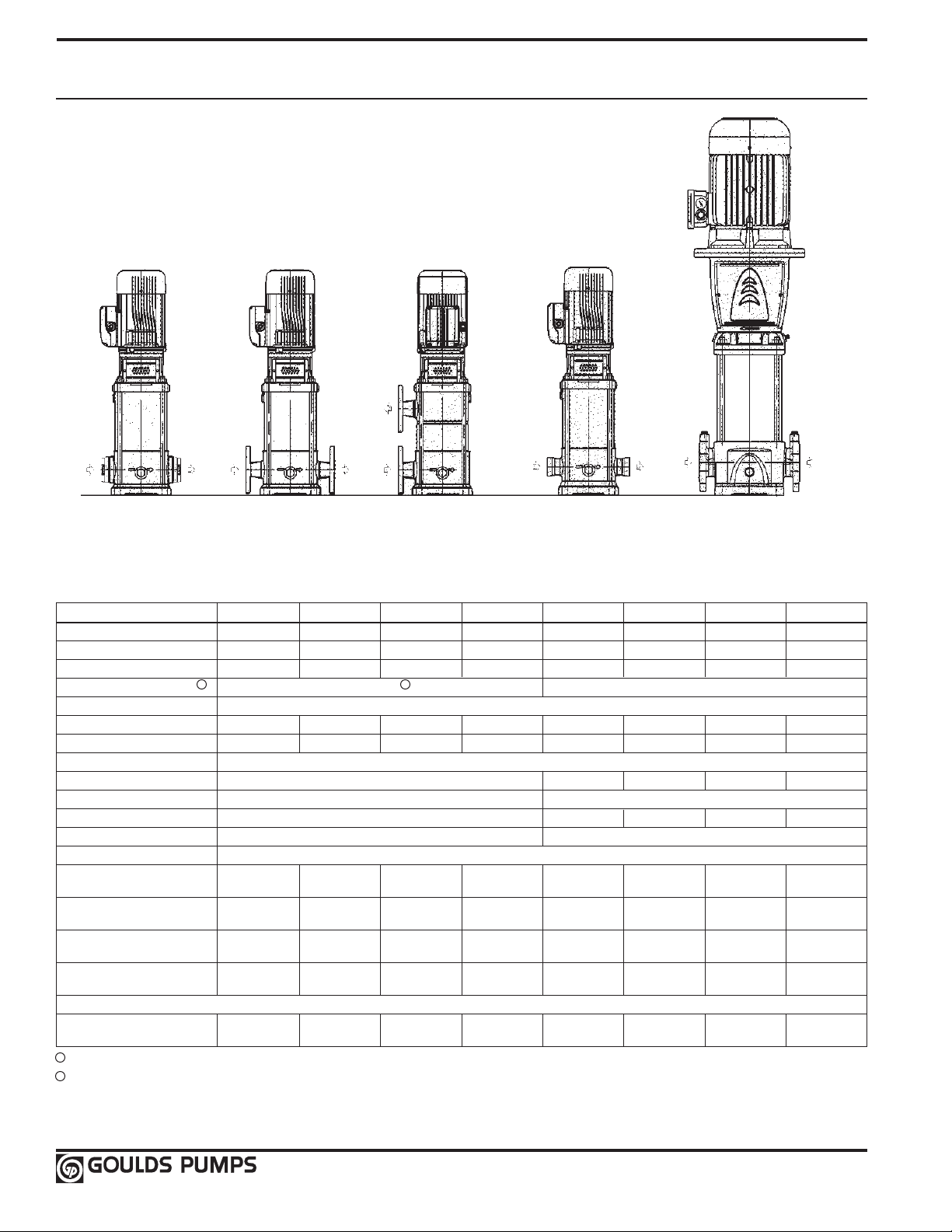
General Characteristics
2-pole
SVA
1SV, 2SV, 3SV
SSV Product Range 1SV 2SV 3SV 4SV 33SV 46SV 66SV 92SV
Nominal Flow (GPM) 15 30 60 85 150 220 350 450
Flow Range (GPM) 2 – 22 6 – 40 11 – 75 17 – 110 30 – 195 45 – 285 70 – 420 90 – 580
Max. Head (Ft) 1100 945 1005 930 1125 1210 850 715
Max. Working Pressure (PSI) 2 360 PSIG 1 360 / 580 PSIG
Temperature Range -20ºF to 250ºF (-30ºC to -121ºC)
Motor Power (HP) ½ – 5 HP ¾ – 5 HP 2 – 15 HP 5 – 20 HP 3 – 60 HP 7½ – 75 HP 10 – 75 HP 15 – 75 HP
Max. Pump Efficiency 44% 58% 64% 67% 76% 78% 78% 80%
Material of Construction
SVA AISI 304SS – – – –
SVB AISI 304SS Cast Iron / AISI 316L
SVC AISI 304SS – – – –
SVD AISI 316LSS Cast Stainless Steel / AISI 316L
Connection Sizes
SVA – Oval NPT
(female) (female) (female)
SVB – Round ANSI 1¼" 1¼" 2" 2" 2½" 3" 4" 4"
Size/Class 300# 300# 300# 300# 125/250# 1325/250# 125/250# 125/250#
SVC – Top/Bottom Round 1¼" 1¼" 2" 2"
ANSI – Size/Class 300# 300# 300# 300#
SVD – Round ANSI 1¼" 1¼" 2" 2" 2½" 3" 4" 4"
Size/Class 300# 300# 300# 300# 150/300# 150/300# 150/200# 150/300#
Optional Connections (on request)
Victaulic (PJE)
(Victaulic) (Victaulic) (Victaulic) (Victaulic)
1 Some staging may have MAWP of 580 psi (40 bar).
2 See pages 53-60 for specific details.
1" NPT 1¼" NPT 1½" NPT
1¼" 1¼" 2" 2"
SVB, SVD
1SV, 2SV, 3SV, 4SV
SVC
1SV, 2SV, 3SV, 4SV
VICTAULIC
1SV, 2SV, 3SV, 4SV
–
SVB, SVD
33SV, 46SV, 66SV, 92SV
– – – –
– – – –
– – – –
4
Page 7
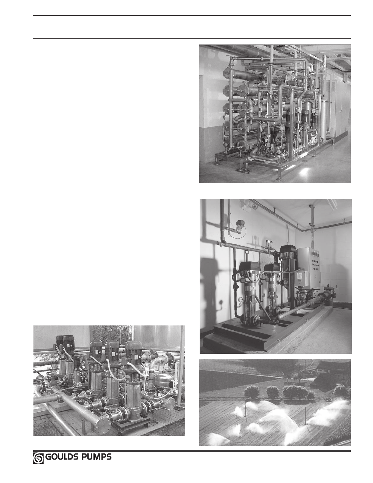
Typical Applications of SSV Series Multi-Stage Pumps
Water Supply and Pressure Boosting
• Pressure boosting in buildings, hotels, residential complexes
• Pressure booster stations, supply of water networks
• Booster packages
Water Treatment
• Ultrafiltration systems
• Reverse osmosis systems
• Water softeners and de-mineralization
• Distillation systems
• Filtration
Light Industry
• Washing and cleaning plants (washing and degreasing of mechanical
parts, car and truck wash tunnels, washing of electronic industry circuits)
• Commercial washers
• Firefighting system pumps
Irrigation and Agriculture
• Greenhouses
• Humidifiers
• Sprinkler irrigation
Heating, Ventilation and Air Conditioning (HVAC)
• Cooling towers and systems
• Temperature control systems
• Refrigerators
• Induction heating
• Heat exchangers
• Boilers
• Water recirculation and heating
5
Page 8

SSV Product Line
Numbering System for 1 – 4SV
The various versions of the SSV line are identified by a product code number on the pump label. This number is also
the catalog number for the pump. The meaning of each digit in the product code number is shown below.
Note: Not all combinations are possible. Consult your G&L distributor.
Example Product Code
2 SV A 1 D 2 B 1 H
Options: H = Horizontal mount, refer to back cover
VIC = Victaulic connections (1SVB/D – 4SVB/D only)
Mechanical Seal Options:
Code No. Rotary Stationary Elastomer Reference Application
0 High Temp. General
Carbon Silicon Viton Service
4 Silicon Carbide Carbide
Graphite Filled Graphite
6 High Temp. Filled EPR Boiler Feed
Carbon
Number of Stages:
B = 2 D = 4 F = 6 H = 8 K = 10 M = 12 P = 14 R = 16 V = 20 Z = 24
C = 3 E = 5 G = 7 J = 9 L = 11 N = 13 Q = 15 T = 18 X = 22
Driver: (50 Hz, no single phase number 0, 1, 4)
1 = 1 PH, ODP 3 = 575V, ODP 5 = 3 PH, TEFC 7 = 3 PH, XP 9 = 3 PH, TEFC with premium efficiency
2 = 3 PH, ODP 4 = 1 PH, TEFC 6 = 575V, TEFC 8 = 575V, XP 0 = 1 PH, XP
HP Rating: C = 1⁄2 E = 1 G = 2 J = 5 L = 10 N = 20
D = 3⁄4 F = 11⁄2 H = 3 K = 71⁄2 M = 15 P = 25
Hertz/RPM:
2 = 50 Hz, 2900 RPM, 190-380 V, (50 Hz motor) 4 = 50 Hz, 2900 RPM, 460 V 6 = 60 Hz, 3500 RPM, 380 V, Y-DELTA
7 = 60 Hz, 1750 RPM, 208-230, 460 V
Material and Suction/Discharge:
A = 304 stainless steel, in-line NPT threaded oval flange connections (1, 2, 3 only)
B = 304 stainless steel, in-line ANSI flange (1, 2, 3, 4SV)
C = 304 stainless steel, top/bottom ANSI flange connections
D = 316 stainless steel, in-line ANSI flange
Product Line: Stainless Vertical
Nominal Flow: 1 = 15 GPM 2 = 28 GPM 3 = 55 GPM
4 = 86 GPM
1 = 60 Hz, 3500 RPM 3 = 60 Hz, 3500 RPM, 380 V 5 = 60 Hz, 3500 RPM, 220-380 V, D.O.L.
Abrasive
Rating Plate 1, 2, 3 and 4SV
3
G&L Pumps
SSV™
CATALOG NUMBER
2
5
GPM FEET RPM
DO NOT OPERATE AT CLOSED DISCHARGE
Goulds Pumps, ITT Industries, Inc.
6
1 Goulds Catalog Number
2 Capacity Range
1
4
7
3 TDH Range
4 Rated Speed
5 Rated Horsepower
6 Maximum Operating Pressure
7 Maximum Operating Temperature
8 Pump Serial Number
8
6
Page 9

SSV Product Line
Numbering System for 33 – 92SV
The various versions of the SSV line are identified by a product code number on the pump label. This number is also
the catalog number for the pump. The meaning of each digit in the product code number is shown below.
Note: Not all combinations are possible. Consult your G&L distributor.
Example Product Code
33 SV B G 1 2 R 6 T A H
Pump Options (optional – to be listed in sequential order)
H = Horizontal mounting D = High Pressure Pump (40 Bar)
Q= 1.0 Service Factor Version (AQ) T = Alternative Motor Frame
Seal Options:
Code No. Rotary Stationary Elastomers
A
Mechanical Seal
C
D EPR
Cartridge Seal
P
– Metal parts on all seals are 316SS.
– Silicon carbide is graphite filled.
B
L
Silicon Carbide
Silicon Carbide
Graphite Filled
EPR
Silicon Carbide
Carbon Viton
Silicon Carbide EPR
Motor Enclosure:
D = ODP T = TEFC
X = Explosion Proof P = TEFC Premium Effy
Motor Voltage:
1 = 115/230 2 = 230 3 = 230/460 4 = 460
5 = 575 6 = 208-230/460 7 = 200 8 = 190/380
HP Rating:
G = 2 HP M = 15 HP S = 50 HP
H = 3 HP N = 20 HP T = 60 HP
J = 5 HP P = 25 HP U = 75 HP
K = 7½ HP Q = 30 HP
L = 10 HP R = 40 HP
Motor Hertz/Speed/Phase:
1 = 60 Hz/3500/1 2 = 60 Hz/3500/3 3 = 60 Hz/1750/1 4 = 60 Hz/1750/3
5 = 50 Hz/2900/1 6 = 50 Hz/2900/3 7 = 50 Hz/1450/1 8 = 50 Hz/1450/3
9 = 60 Hz/Variable/3
Number of Reduced Impellers (can be 0, 1, 2) *
Total Bowls/Stages:
A = 1 E = 5 J = 9
B = 2 F = 6 K = 10
C = 3 G = 7
D = 4 H = 8
Flange Orientation:
B = Cast Iron/316 stainless steel, in-line ANSI flange
D = 316 stainless steel, in-line ANSI flange
Product Line:
Stainless Vertical Vertical
Nominal Flow:
33 = 150 GPM 66 = 350 GPM
46 = 225 GPM 92 = 450 GPM
* NOTE: Indicates number of reduced diameter
impellers in the total staging.
(2 would indicate 2 reduced diameter impellers)
Viton
Carbon
Viton
①
①
Alternative motor frame will be next larger frame size than
what is standard.
7
Page 10
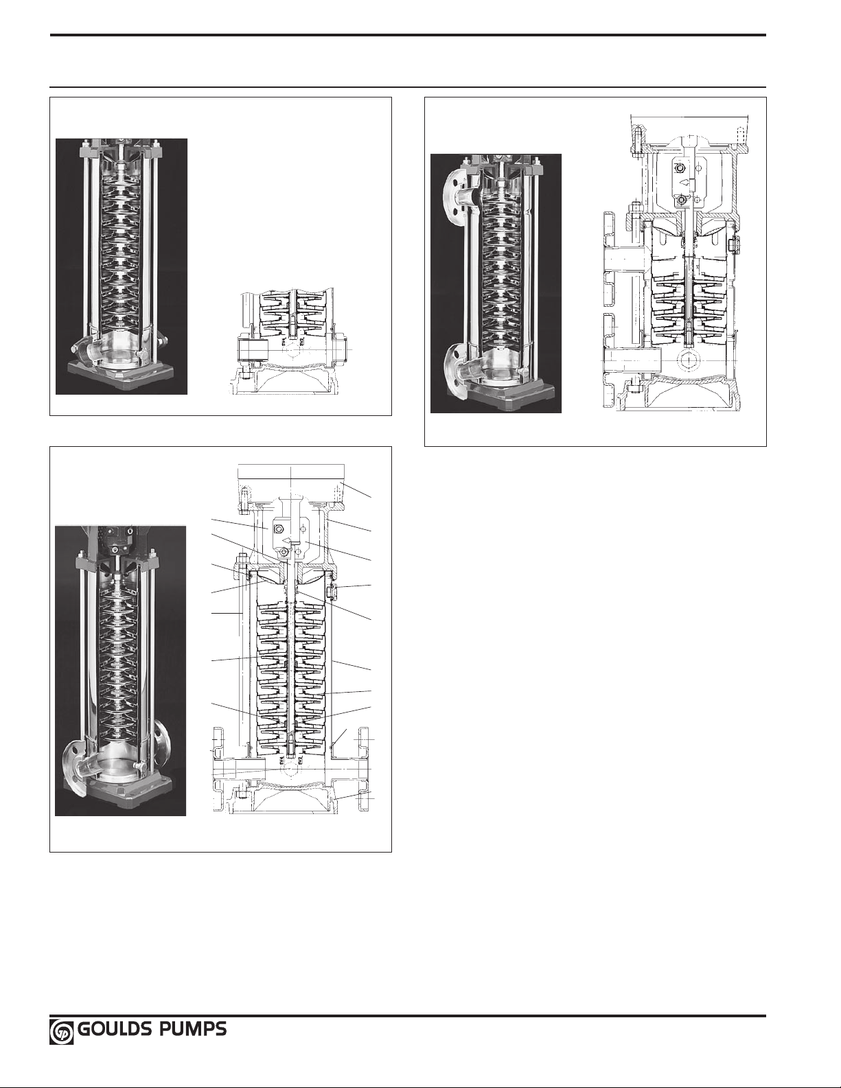
Base Models: 1SV, 2SV, 3SV
1
3
2
7
6
10
11
13
16
17
4
15
9
5
8
12
14
7
9
and 4SV Major Components
Series SVA
In-line NPT connections
Series SVB or SVD
Series SVC
Top and bottom suction/discharge design
In-line ANSI
flange connections
8
Page 11

Base Models: 1SV, 2SV, 3SV
and 4SV Major Components
SVA, SVB, SVC (1, 2, 3 and 4 SSV Sizes) SVD (1, 2, 3 and 4 SSV Sizes)
No. Description
1 NEMA Vertical Motor
2
Rigid Coupling
Cast Iron A48 Class 25 JL1030 Cast Iron A48 Class 25 JL1030
3 Motor Adapter Cast Iron A48 Class 35 JL1040 Cast Iron A48 Class 35 JL1040
4 Coupling Guard Stainless Steel A193-304 1.4301 Stainless Steel A193-304 1.4301
5 Seal Housing Stainless Steel A193-304 1.4301 Stainless Steel A193-316L 1.4404
6 Mechanical Seal See Seal Materials Chart for Complete Details See Materials Chart for Complete Details
7 Plugs, Fill and Drain Stainless Steel/O-Ring A193-316 1.4401 Stainless Steel/O-Ring A193-316 1.4401
8 Tie Rod Zinc Plated Steel B633 1.0765 Zinc Plated Steel B633 1.0765
9 O-Ring, Sleeve Viton (std) EPDM (opt) B633 Viton (std) EPDM (opt) B633
10 Sleeve (casing) Stainless Steel A193-304 1.4301 Stainless Steel A193-316L 1.4404
11 Diffuser Stainless Steel A193-316 1.4401 Stainless Steel A193-316 1.4401
12 Impeller Stainless Steel A193-316 1.4401 Stainless Steel A193-316 1.4401
13 Tungsten Carbide Sleeve Tungsten Carbide Tungsten Carbide
14 Ceramic Bushing Ceramic Ceramic
15 Shaft Stainless Steel A193-304 1.4301 Stainless Steel A193-316 1.4401
16 Pump Body Stainless Steel A193-304 1.4301 Stainless Steel A193-316L 1.4401
17 Pump Base Aluminum B85 AC46100 Aluminum B85 AC46100
Material ASTM DIN Material ASTM DIN
Aluminum B85 AC46100 Aluminum B85 AC46100
9
Page 12
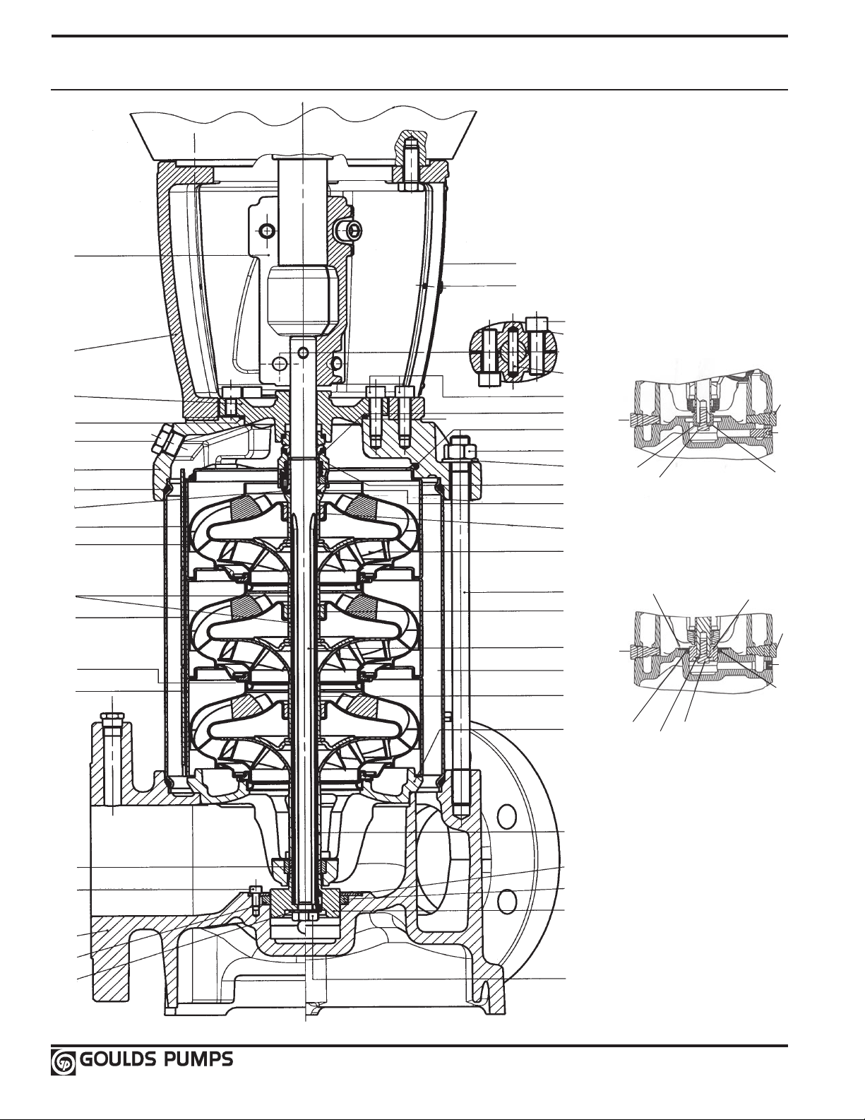
Base Model: 33SV, 46SV, 66SV and 92SV
Major Components
45
44
29
3
16
19
4
38
30
24
31
26
39
25
3
36
6
8
11
13
9
41
49
46
48
5
2
30
20
21
47
35
37
27
27A
32
18
12
18
10
28
LESS PISTON
18
15
34
23
18
14
40
22
33
35
7
42
1
12
28
40
23
10
1
12
10
WITH PISTON
10
Page 13

Base Model: 33SV, 46SV, 66SV and 92SV
Major Components
No. Description
Material ASTM DIN Material ASTM DIN
1 O-Ring, Piston Seal Viton (std) EPDM (opt) Viton (std) EPDM (opt)
2 O-Ring, Mechanical Seal Sleeve Viton (std) EPDM (opt) Viton (std) EPDM (opt)
3 O-Ring, Seal housing Viton (std) EPDM (opt) Viton (std) EPDM (opt)
4 O-Ring, Sleeve Viton (std) EPDM (opt) Viton (std) EPDM (opt)
5 Mechanical Seal
5A Cartridge Seal (not shown)
6 Screw, Guard Stainless Steel A193-304 1.4301 Stainless Steel A193-304 1.4301
7 Screw, Piston Holding Disc Stainless Steel A193-316 1.4401 Stainless Steel A193-316 1.4401
8 Screw, Coupling Zinc Plated Steel B363 Zinc Plated Steel B633
9 Screw, MA and Seal Housing Zinc Plated Steel B633 Zinc Plated Steel B633
10 Screw, Impeller Stainless Steel A193-316 1.4401 Stainless Steel A193-316 1.4401
11 Washer, Coupling Carbon Steel A108 Carbon Steel A108
12 Washer, Impeller Stainless Steel A193-316 1.4401 Stainless Steel A193-316 1.4401
13 Pin, Coupling Carbon Steel A108 Carbon Steel A108
14 Plug, with Piston Stainless Steel A193-316 1.4401 Stainless Steel A193-316 1.4401
15 Plug, without Piston Stainless Steel A193-316 1.4401 Stainless Steel A193-316 1.4401
16 Plug, Fill Stainless Steel/O-Ring A193-316 1.4401 Stainless Steel/O-Ring A193-316 1.4401
17 Plug, Vent (not shown) Stainless Steel/O-Ring A193-316 1.4401 Stainless Steel/O-Ring A193-316 1.4401
18 Plug, Drain Stainless Steel/O-Ring A193-316 1.4401 Stainless Steel/O-Ring A193-316 1.4401
19 Pump Head Cast Iron A48 Class 35 JL1030 Stainless Steel 316 CF8M 1.4408
20 Impeller, Full Diameter Stainless Steel A193-316L 1.4404 Stainless Steel A193-316L 1.4404
21 Impeller, Reduced Diameter Stainless Steel A193-316L 1.4404 Stainless Steel A193-316L 1.4404
22 Lower Bearing Assembly SS/Cast Iron A193-316L/A48 Class 35 1.4404/JL1030 Stainless Steel A193-316L/316 CF8M 1.4404/1.4408
23 Piston Dupless SS A182-F51 1.4462 Dupless SS A182-F51 1.4462
24 Diffuser, Final Stainless Steel A193-316L 1.4404 Stainless Steel A193-316L 1.4404
25 Diffuser with Carbon Bushing Stainless Steel A193-316L 1.4404 Stainless Steel A193-316L 1.4404
26 Diffuser with Tungsten Bushing Stainless Steel A193-316L 1.4404 Stainless Steel A193-316L 1.4404
27 Outer Sleeve, 25 Bar Stainless Steel A193-316L 1.4404 Stainless Steel A193-316L 1.4404
27A Outer Sleeve, 40 Bar Stanless Steel A193-316L 1.4404 Stainless Steel A193-316L 1.4404
28 Holding Disc, Piston Seal Stainless Steel A193-316L 1.4404 Stainless Steel A193-316L 1.4404
29 Seal Housing Cast Iron A48 Class 35 JL1030 Stainless Steel 316 CF8M 1.4408
30 Spacer, Impeller Final Stainless Steel A193-316 1.4401 Stainless Steel A193-316 1.4401
31 Spacer, Shaft Bushing Stainless Steel A193-316 1.4401 Stainless Steel A193-316 1.4401
32 Spacer, Impeller Stainless Steel A193-316 1.4401 Stainless Steel A193-316 1.4401
33 Spacer, Impeller Lower (66-92SV) Stainless Steel A193-316 1.4401 Stainless Steel A193-316 1.4401
34 Bushing, Non-Piston Stainless Steel A193-316 1.4401 Stainless Steel A193-316 1.4401
35 Tungsten Carbide Bushing Tungsten Carbide Tungsten Carbide
36 Coupling Guard Stainless Steel A193-304 1.4301 Stainless Steel 304 1.4301
37 Shaft Dupless SS A182-F51 1.4462 Dupless SS A183-F51 1.4462
38 Mechanical Seal Shaft Sleeve Stainless Steel A193-316 1.4401 Stainless Steel A193-316 1.4401
39 Wear Ring, Impeller PPS Glass Filled PPS Glass Filled
40 Piston Seal Impregnated Carbon Impregnated Carbon
41 Stop Ring, Impeller Stainless Steel A193-316 1.4401 Stainless Steel A193-316 1.4401
42 Pump Body Cast Iron A48 Class 35 JL1030 Stainless Steel 316 CF8M 1.4408
43 Motor Adapter Plate (not shown) Cast Iron A48 Class 25 JL1030 Cast Iron A48 Class 25 JL1030
44 Motor Adapter Cast Iron A48 Class 25 JL1030 Cast Iron A48 Class 25 JL1030
45 Coupling, Half Cast Iron A48 Class 25 JL1030 Cast Iron A48 Class 25 JL1030
46 Nut, Tie-Rod Zinc Plated Steel B633 Zinc Plated Steel B633
47 Tie-Rod Zinc Plated Steel B633 Zinc Plated Steel B633
48 Washer, Tie-Rod Zinc Plated Steel B633 Zinc Plated Steel B633
49 Spring, Final Diffuser Stainless Steel A193-316 1.4401 Stainless Steel A193-316 1.4401
SVB (33 – 92SV) SVD (33 – 92SV)
See Seal Materials Chart for Complete Detail See Seal Materials Chart for Complete Details
11
Page 14
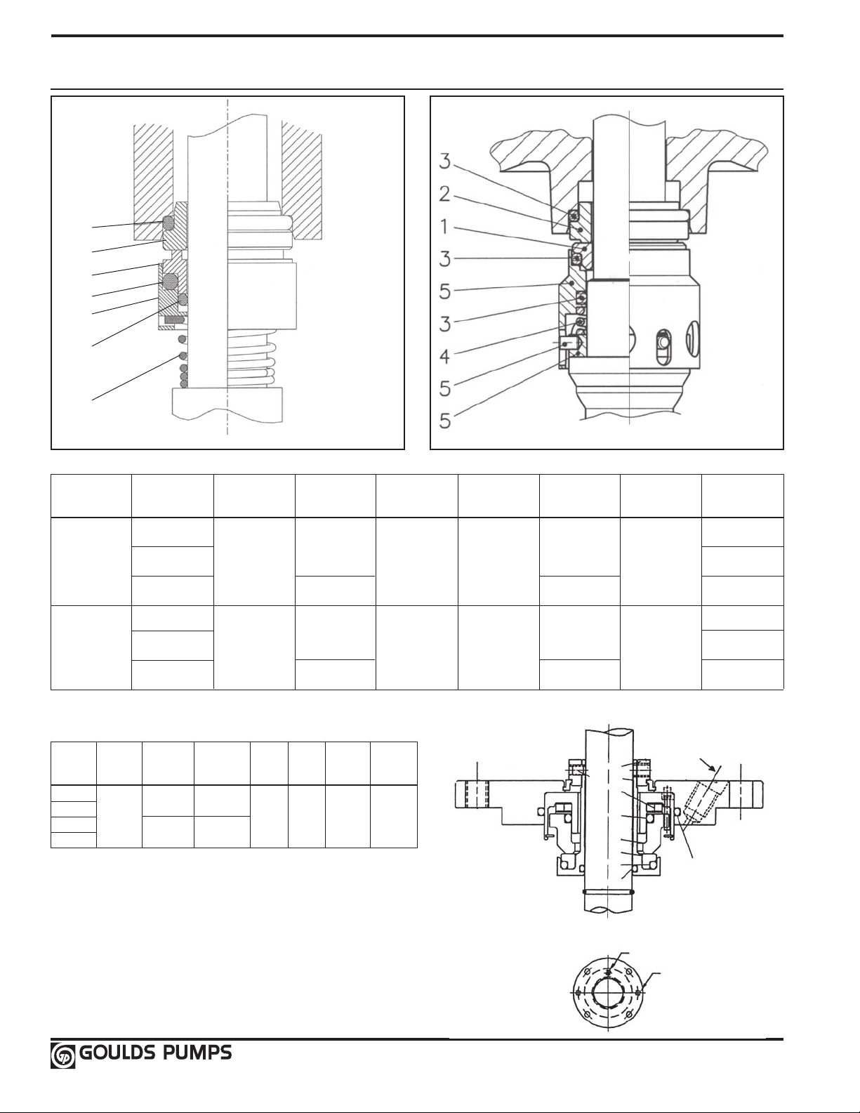
SSV Mechanical Seals
3
2
1
3
5
3
4
1 – 4SV 33 – 92SV
Pump Components Temp. Limits Working Application Use
1 2 3 4 5 ºF (ºC) Pressure
1SV
2SV
Silicon Carbide Silicon Carbide
3SV
Graphite Filled Graphite Filled (25 bar)
4SV
(-34 – 150ºC)
33SV
46SV
Silicon Carbide Silicon Carbide
66SV
Graphite Filled Graphite Filled (40 bar)
92SV
Carbon
(-30 – 120ºC)
NOTE: Pump max. temperature limit is 250ºF.
Rotating Face Stationary Face Elastomers Spring
Carbon
Carbon
Carbon
Viton
-30 – 300ºF
EPR
Viton
-22 – 250ºF
EPR
Metal Elastomer Maximum
-14 – 392ºF
(-10 – 200ºC)
316SS 316SS
316SS 316SS
363 psi
-14 – 392ºF
(-10 – 200ºC)
580 psi
General Service
Abrasive
Boiler Feed
General Service
Abrasive
Boiler Feed
OPTIONAL CARTRIDGE SEAL
Rotating Stationary
Pump Face Face
1 2 3 4 5 6
33SV
46SV
66SV
92SV
Silicon
Carbide
Carbon Viton
Silicon
Carbide
Elastomers Spring Sleeve Set Screw
316SS 316SS 300SS 316SS
EPR
Locking
Collar
6
VENT 1⁄8 NPT
7
5
4
3
2
1
3
3
CARTRIDGE SEAL
VENT 1⁄8 NPT
PULLER
HOLES
12
Page 15
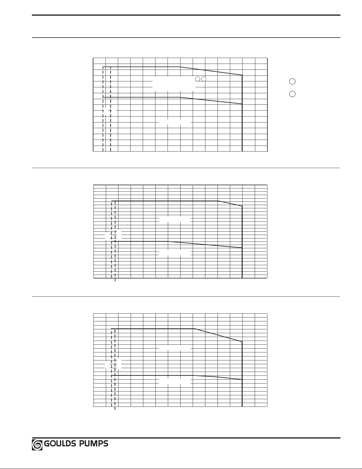
Maximum Allowable Working Pressure Charts
-50 0 50 100 150 200 250 300
0
50
100
150
200
250
300
350
400
1SVA / 2SVA / 3SVA
VITON
TEMPERATURE (F)
MAXIMUM ALLOWABLE WORKING PRESSURE (PSIG)
1SV, 2SV, 3SV, 4SV
304SS / 316SS (SVA, SVB, SVC, SVD)
-30 -14
1SVB / 2SVB / 3SVB / 4SVB
1SVC / 2SVC / 3SVC / 4SVC
1SVD / 2SVD / 3SVD / 4SVD
1 2
EPR
-50 0 50 100 150 200 250 300
0
100
400
200
500
300
600
700
VITON
TEMPERATURE (F)
MAXIMUM ALLOWABLE WORKING PRESSURE (PSIG)
33SV, 46SV, 66SV, 92SV
316SS (CF8M)
FLANGE CLASS 150
FLANGE CLASS 300
-20
-14
EPR
-50 0 50 100 150 200 250 300
0
100
400
200
500
300
600
TEMPERATURE (F)
MAXIMUM ALLOWABLE WORKING PRESSURE (PSIG)
33SV, 46SV, 66SV, 92SV
Cast Iron Class 35 (ASTM A48)
-20
-14
FLANGE CLASS 125
FLANGE CLASS 250
VITON
EPR
NOTES:
1 Pressure rating for
victaulic connections
2 Some staging may have
higher pressure rating.
See pages 55-56.
13
Page 16

Motor Data – Starts per Hour / Minimum Run Time
HP Max Starts per Hour (evenly distributed) Min. run time between starts (seconds)
1 15 75
1.5 13 76
2 12 77
3 9 80
5 8 83
7.5 7 88
10 6 92
15 5 100
20 5 110
25 5 115
30 4 120
40 4 130
50 3 145
60 3 170
75 3 180
NOTE(S)
1) Recommended motor starts per hour and minimum run time calculated based on NEMA standards MG1-12.44 in accordance to
manufacturers allowable tolerance for heat rise and insulation breakdown.
2) Applied voltage and frequency in accordance with NEMA MG1-12.44
3) Starts based on NEMA three phase design A and design B AC induction motors.
4) External load WK2 is equal to or less than the values listed in NEMA MG1-12.54
5) Applicable to all NEMA (JM, JP, T and TC frame) motors used for Goulds Pumps products.
6) Applicable to three phase motors only.
14
Page 17
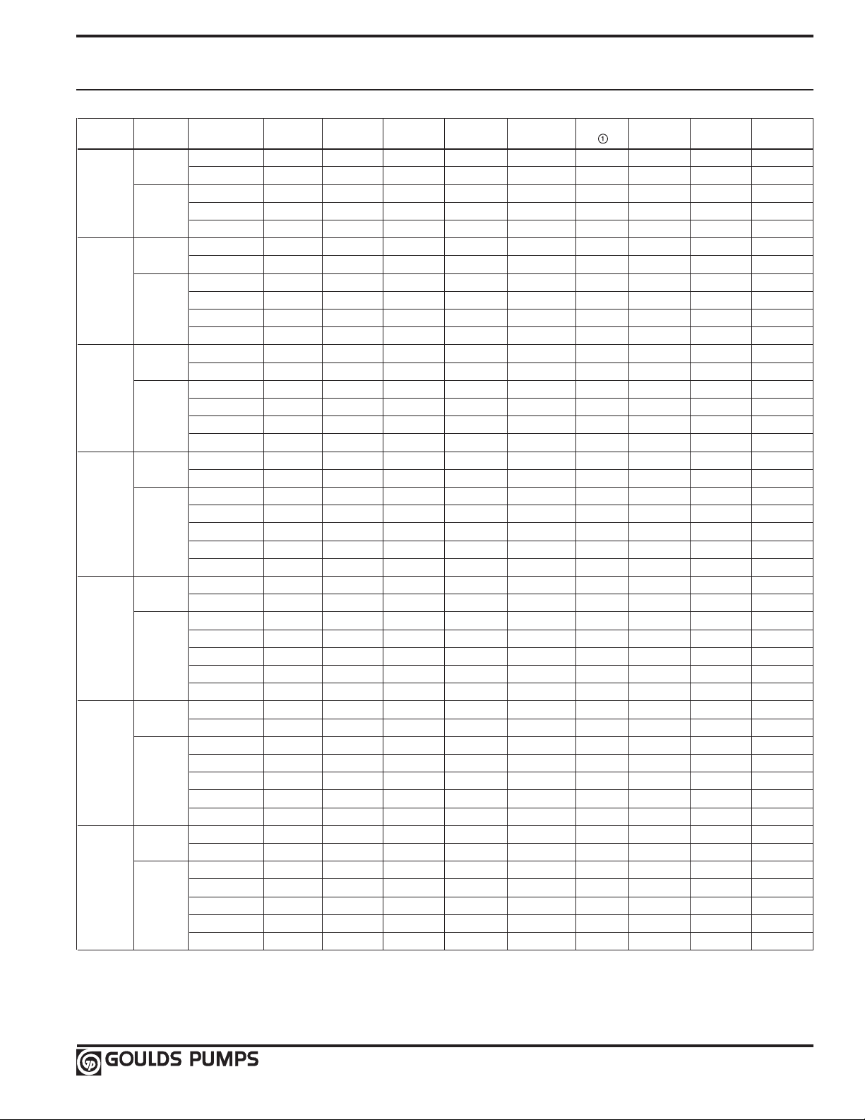
Motor Data
3500 RPM, 60Hz
HP Phase Enclosure
Voltage Frame PN ② ¹ Class
TEFC 115/230 56C V04722 7/3.6-3.5 7.9/4.06-3.95 21 1.15 66 B
½ ODP 230/460 56C V04741 2.1/2-1 2.52/2.4-1.2 6 1.25 68 B
3 TEFC 230/460 56C V04742 2.1/2-1 2.52/2.4-1.2 6 1.25 68 B
X-Proof 230/460 56C V04743 2.1/2-1 NA 6 1 68 B
TEFC 115/230 56C V05722 9.6/5-4.8 11.4/5.94-5.7 28 1.25 66 B
¾ ODP 230/460 56C V05741 2.7-2.6/1.3 3.15-3/1.5 7.6 1.25 74 B
X-Proof 230/460 56C V05743 2.7-2.6/1.4 NA 7.6 1 74 B
Prem. Eff. TEFC 230/460 56C V05742PE 2.0/1.0 2.3/1.15 7 1.15 82.5 B
TEFC 115/230 56C V06722 11/5.5 13.5/6.75 38.5 1.25 66 B
1 ODP 230/460 56C V06741 3.7-3.6/1.8 3.99-3.8/1.9 11 1.25 75.5 B
X-Proof 230/460 56C V06743 3.7-3.6/1.9 NA 11 1 75.5 B
Prem. Eff. TEFC 230/460 56C V06742PE 2.8/1.4 3.12/1.56 12.1 1.25 84.5 B
TEFC 115/230 56C V07722 16/8.4-8 18/10-9 50 1.15 70 B
ODP 230/460 56C V07741 4.9-4.6/2.3 5.3-5.1/2.54 18.4 1.15 80 B
1½ TEFC 230/460 56C V07742 4.9-4.6/2.3 5.3-5.1/2.54 18.4 1.15 80 B
3 X-Proof 230/460 56C V07743 5-4.6/2.3 NA 16 1 75.5 B
Prem. Eff. ODP 230/460 56C V07741PE 4.2/2.1 4.6/2.3 16 1.15 85.5 B
Prem. Eff. TEFC 230/460 56C V07742PE 4.0/2.0 4.5/2.25 20.1 1.15 85.5 B
1 ODP 115/230 56C V08721 24/12.6-12 28.6/14.3 80 1.15 70 B
TEFC 115/230 56C V08722 23/12-11.5 24.2/12.1 78 1.15 74 B
ODP 208-230/460 56C V08741 6.2-5.8/2.9 7.2-6.52/3.26 22 1.15 80 B
2 TEFC 208-230/460 56C V08742 6.2-5.8/2.9 7.2-6.52/3.26 22 1.15 80 B
3 X-Proof 208-230/460 56C V08743 5.4/2.7 N/A 17.5 1 78.5 B
Prem. Eff. ODP 208-230/460 56C V08741PE 5.5-5/2.5 6.2-5.6/2.8 22 1.15 86.5 B
Prem. Eff. TEFC 208-230/460 56C V08742PE 5/4.75-2.5 6.4-5.8/2.9 30 1.15 86.5 B
TEFC 115/230 56C V09722 27/13.5 33/18/16.5 11.4 1.15 80 F
ODP 208-230/460 56C V09741 8.5-8/4 10-9/4.5 30.9 1.15 80 F
3 TEFC 208-230/460 56C V09742 8.1-7.6/3.8 9.5-8.6/4.3 32.9 1.15 82.5 F
3 X-Proof 208-230/460 56C V09743 7.8-7.4/3.7 NA 27 1 82.5 F
Prem. Eff. ODP 208-230/460 56C V09741PE 7.4/3.7 9.1-8.2/4.1 29 1.15 87.5 F
Prem. Eff. TEFC 208-230/460 184TC V09742PE 6.8/3.4 8.5-7.7/3.8 32 1.15 88.5 F
TEFC 208-230 184TC V10722A 23.5 41.8-37.8 110 1.15 84 F
ODP 208-230/460 184TC V10741A 13.1-11.5/5.7 15.3-13.8/6.9 48 1.15 84 F
5 TEFC 208-230/460 184TC V10742A 13.2-12/6 15-13.6/6.8 47 1.15 85.5 F
3 X-Proof 230/460 184TC V10743A 13.2-12/6 NA 47 1 85.5 F
Prem. Eff. ODP 208-230/460 184TC V10741APE 11.2/5.6 14.4-13/6.5 55 1.15 90.2 B
Prem. Eff. TEFC 208-230/460 184TC V10742APE 11.2/5.7 14.4-13/6.5 55 1.15 90.2 F
ODP 115/230 56C V04721 7/3.6-3.5 7.9/4.06-3.95 21 1.15 66 B
1
ODP 115/230 56C V05721 9.4/4.9-4.7 10.8/5.63-5.4 26 1.25 72 B
1
TEFC 230/460 56C V05742 2.7-2.6/1.3 3.15-3/1.5 7.6 1.25 74 B
3
ODP 115/230 56C V06721 15/7.9-7.5 15.8/8.217.9 48 1.25 65 B
1
TEFC 230/460 56C V06742 3.7-3.6/1.8 3.99-3.8/1.9 11 1.25 75.5 B
3
ODP 115/230 56C V07721 12.8/7-6.4 14.5/7.9-7.3 76 1.15 80 B
1
ODP 230 56C V09721 14.4/13 16.4-14.8 108 1.15 82.5 B
1
ODP 208-230 184TC V10721A 24-23 30.1-27.2 125 1.15 75 F
1
Nameplate NEMA Goulds
FLA SFA
LRA
S.F. Efficiency
Insulation
15
Page 18
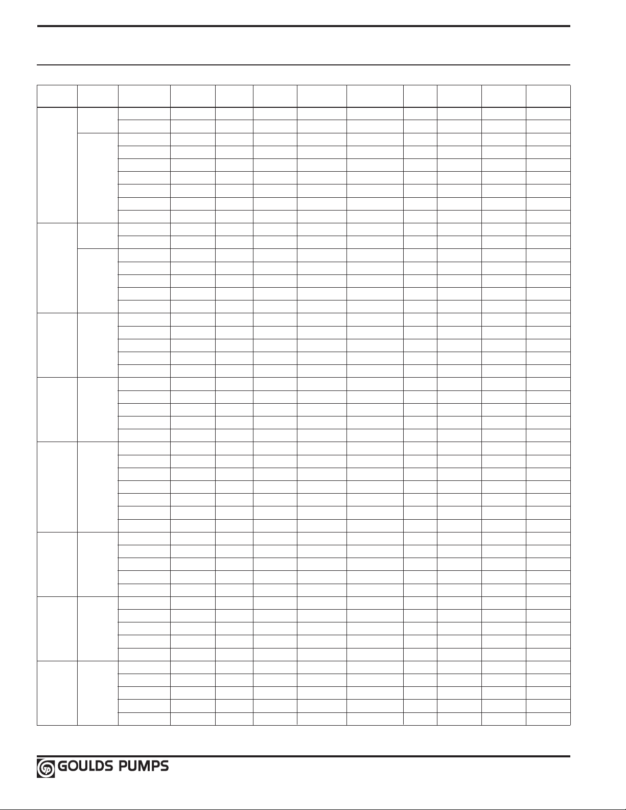
Motor Data
3500 RPM, 60Hz
HP Phase Enclosure
Voltage Frame PN ② ① Class
TEFC 230 213TC V11722 35 NA 220 1 83 F
ODP 208-230/460 184TC V11741A 19 22.3-20.2/10.1 76 1.15 88.5 F
ODP 208-230/460 184TC V11741BB 19-18/9 22.3-20.2/10.1 76 1.15 85.5 B
7.5 TEFC 208-230/460 184TC V11742BB 18.3-17.4/8.7 21.7-19.7/9.8 99 1.15 88.5 F
3 TEFC 208-230/460 184TC V11742A 18.5/17.4 21.7-19.6/9.8 94 1.15 88.5 F
X-Proof 230/460 184TC V11743A 17.6/8.8 N/A 76 1.15 87.5 B
Prem. Eff. ODP 208-230/460 184TC V11741APE 16.8/8.4 21.2-19.2/9.6 87 1.15 90.2 F
Prem. Eff. TEFC 230/460 213TC V11742APE 17.8/8.9 20.2/10.1 75 1.15 90.2 F
TEFC 230 213TC V12722 40 NA 284 1 82 F
ODP 208-230/460 213TC V12741 25.6-23.2/11.6 29.9-27/13.5 67 1.15 88.5 F
10 TEFC 208-230/460 215TC V12742 25-24/12 30.5-27.6/13.8 105 1.15 85.5 F
3 X-PROOF 230/460 215TC V12743 23.2/11.6 35.2/17.6 99.2 1.15 89.5 F
Prem. Eff. ODP 208-230/460 213TC V12741PE 23/11.5 29.2-26.4/13.2 98 1.15 91.7 F
Prem. Eff. TEFC 230/460 215TC V12742PE 23.8/11.9 27.6/13.8 112 1.15 89.5 F
ODP 208-230/460 215TC V13741 35/17.5 43.8-39.6/19.8 124 1.15 89.5 F
TEFC 208-230/460 254TC V13742 35/17.5 43-39/19.5 165 1.15 86.5 F
15 3 X-Proof 230/460 254TC V13743 35.6/16.8 38.8/19.4 108 1.15 90.2 F
Prem. Eff. ODP 208-230/460 215TC V13741PE 34/17 43.8-39.6/19.8 143 1.15 91.7 F
Prem. Eff. TEFC 208-230/460 254TC V13742PE 34.4/17.2 43.8-39.6/19.8 112 1.15 91.7 F
ODP 230/460 254TC V14741 46/23 51.4/25.7 175 1.15 87.5 F
TEFC 208-230/460 256TC V14742 46/23 59.3-53.6/26.8 160 1.15 89.5 F
20 3 X-Proof 230/460 256TC V14743 46/23 51.6/25.8 153 1.15 90.2 F
Prem. Eff. ODP 208-230/460 254TC V14741PE 45/22.5 57.5-52/26 144.8 1.15 92.4 F
Prem. Eff. TEFC 208-230/460 256TC V14742PE 46/23 57.5-52/26 201 1.15 92.4 F
ODP 208-230/460 256TC V15741 60/30 75.9-68.6/34.3 160 1.15 88.5 F
TEFC 208-230/460 284TC V15742 59/29.5 74.8-67.6/33.8 182 1.15 88.5 F
ODP 208-230/460 256TC V15741BB 65-60/30 75.9-68.6/34.3 160 1.15 88.5 B
25 3 TEFC 208-230/460 256TC V15742BB 62-56/28 72.3-65.4/32.7 184 1.15 90.2 F
X-Proof 230/460 284TC V15743 57/28.5 66/33 204 1.15 91 F
Prem. Eff. ODP 230/460 256TC V15741PE 58/29 66.8/33.4 204 1.15 92.4 F
Prem. Eff. TEFC 230/460 284TC V15742PE 56/28 69.9-63.2/31.6 236 1.15 93 F
ODP 208-230/460 284TC V16741 70/35 80.6/40.3 190 1.15 91 F
TEFC 208-230/460 284TC V16742 68/34 86.7-78.4/39.2 225 1.15 91 F
30 3 X-Proof 230/460 286TC V16743 70/35 80.5/40.25 248 1.15 91 F
Prem. Eff. ODP 230/460 284TC V16741PE 68/34 77.4/38.7 234 1.15 93.6 F
Prem. Eff. TEFC 230/460 286TC V16742PE 66/33 83.8-75.8/37.9 281 1.15 93 F
ODP 230/460 284TC V17741 96/48 108.4/54.2 271 1.15 91 F
TEFC 230/460 284TC V17742 90/45 103.2/51.6 322 1.15 90.2 F
40 3 X-Proof 230/460 324TSC V17743 90/45 104.2/52.1 285 1.15 91.7 F
Prem. Eff. ODP 230/460 286TC V17741PE 110/55 127.4/63.7 408 1.15 94.1 F
Prem. Eff. TEFC 230/460 324TSC V17742PE 90/45 102.2/51.1 286 1.15 93.6 F
ODP 230/460 326TSC V18741S 118/59 137/68.5 320 1.15 89.5 F
TEFC 230/460 326TSC V18742S 112/56 141.8-128.2/64.1 430 1.15 92.4 F
50 3 X-Proof 230/460 326TSC V18743S 112.00/56 129/64.5 407 1.15 92.4 F
Prem. Eff. ODP 230/460 324TSC V18741SPE 110/55 127.4/63.7 408 1.15 94.1 F
Prem. Eff. TEFC 230/460 326TSC V18742SPE 108/54 124.8/62.4 422 1.15 94.1 F
ODP 230 213TC V11721 29 35 185 1.15 84 F
1
ODP 230 213TC V12721 48-46 51.6 280 1.15 83 F
1
Nameplate NEMA Goulds
FLA SFA
LRA
S.F. Efficiency
Insulation
16
Page 19

Motor Data
HP Phase Enclosure
Voltage Frame PN ② ¹ Class
ODP 230/460 326TSC V19741S 136/68 157.4/78.7 472 1.15 93 F
TEFC 230/460 364TSC V19742S 138/69 173.6-157/78.5 422 1.15 90.2 F
60 3 X-Proof 230/460 364TSC V19743S 134/67 154.4/77.2 448 1.15 93 F
Prem. Eff. ODP 230/460 326TSC V19741SPE 130/65 149.4/74.7 493 1.15 94.5 F
Prem. Eff. TEFC 230/460 364TSC V19742SPE 134/67 150.8/75.4 580 1.15 94.1 F
ODP 230/460 365TSC V20741S 168/84 213-193/96.5 639 1.15 93 F
TEFC 230/460 365TSC V20742S 168/84 213-192.8/96.4 650 1.15 91 F
75 3 X-Proof 230/460 365TSC V20743S 164/82 189/94.5 618 1.15 93 F
Prem. Eff. ODP 230/460 364TSC V20741SPE 164/82 188.8/94.4 557 1.15 94.5 F
Prem. Eff. TEFC 230/460 365TSC V20742SPE 166/83 188.8/94.4 740 1.15 94.5 F
NOTES:
① Locked rotor amps are for high voltage only.
② Vertical footless motor PN.
• Motors are suitable for AQUAVAR® Variable Speed Drive.
Above data is for Baldor® TC and TSC frame motors. Specifications subject to change without notice.
Nameplate NEMA Goulds
FLA SFA
LRA
S.F. Efficiency
Insulation
17
Page 20
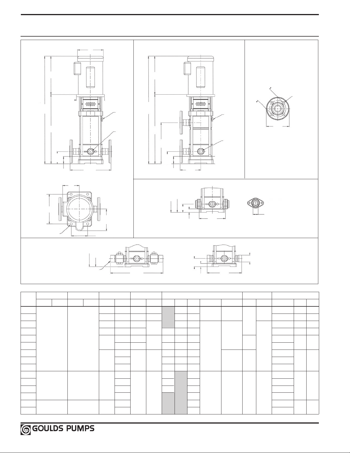
Dimensions and Weights
SVC
FLANGE
SVA
SVB
SVD
1SV Series 3500 RPM
D1
L2
L1 +
L2
L1
2.95
(75)
1.77
(45)
M1
REF
7.09 (180)
Ø .51 (13)
All dimensions are in inches (mm).
9.84
(250)
L5 + L2
(overall)
1¼" NPT
M2
REF
3.94 (100)
L5 (liquid
end)
FILL
3/8 BSP
DRAIN
3/8 BSP
12.60
(320)
L1 +
L2
L2
L1
L3
2.95
(75)
L4 + L2
(overall)
1.77
(45)
L4 (liquid
end)
1.97
(50)
1.97 (50)
4.92
(125)
.79
(20)
6.30
(160)
8.27
(210)
FILL
3/8 BSP
DRAIN
3/8 BSP
Ø 3.94 B.C.
(100)
1.64 (41.7)
Ø .71 (18)
4 HOLES
5.51
(140)
1¼" CLASS 300
1 NPT
VICTAULIC
Frame (1-Phase) Frame (3-Phase) L2 D1 (max.) Weights (lb)
Stage
ODP TEFC ODP TEFC HP L1 ODP TEFC L3 L4 L5 M1 (ref.) M2 (ref.) ODP TEFC Liquid End ODP TEFC
2 ½ 12.69 9.16 9.29 11.69 11.69
3 ¾ 13.63 10.79 9.91 12.69 12.69
4 1 14.63 10.66
5 1½ 15.63 10.67 8.88 14.63 14.63
6 56C 56C
7 17.56 11.19 10.81 16.63 16.63 5.73 7.19 28
8 18.56 11.81 17.56 17.56 29
9 3 19.56 11.57 13.44 12.81 18.56 18.56 5.50 7.16 30 51 56
11 20.50 14.75 20.50 20.50 33
13 23.50 16.75 22.50 35
15
16 26.44
18 28.44 27.50 41
20
22 32.44 31.50 46
182-4TC 182-4TC 5
213TC 213TC 7½
16.63 11.19
2
25.44 18.69 24.44 37
13.93 15.43
30.44 29.50 44
13.63 13.63 23 32 40
11.19
9.88 15.63 15.63
12.06
19.69 25.81
5.06 5.19
6.87 6.62 8.50 8.50
6.19
25 40 43
5.55
7.19
21 22 22
6.19
22 24 28
27
39
43 51
75 85
101 124
18
Page 21

1SV Curve 3500 RPM
0
100
200
300
400
500
600
700
0 10 15 25 US GPM
FEET
TOTAL DYNAMIC HEAD
CAPACITY
30
40
50
EFF %
1100
1SV 60 Hz
3500 RPM
0
0.5
HP/STAGE
0 5
m
3
/h
0
50
100
150
200
250
300
350
METERS
1000
800
900
0
8
12
20
4321
10
6
kW/STAGE
0
.30
.20
.10
5
4
2
0.25
NPSHr
0
2
3
1
(m)
(ft)
2 – 16 STAGES
18 – 22 STAGES*
* For vertical shaft installation only.
22 STAGE
20 STAGE
18 STAGE
16 STAGE
13 STAGE
11 STAGE
9 STAGE
8 STAGE
7 STAGE
6 STAGE
5 STAGE
4 STAGE
3 STAGE
2 STAGE
Eff.
BHP
15 STAGE
19
Page 22

Dimensions and Weights
SVC
FLANGE
SVA
SVB
SVD
2SV Series 3500 RPM
D1
L2
L1 +
L2
L1
2.95
(75)
1.77
(45)
M1
REF
7.09 (180)
Ø .51 (13)
1¼" NPT
All dimensions are in inches (mm).
9.84
(250)
L5 + L2
(overall)
M2
REF
3.94 (100)
L5 (liquid
end)
FILL
3/8 BSP
DRAIN
3/8 BSP
12.60
(320)
L1 +
L2
L2
L1
L3
2.95
(75)
L4 + L2
(overall)
1.77
(45)
L4 (liquid
end)
1.97
(50)
1.97 (50)
4.92
(125)
.79
(20)
6.30
(160)
8.27
(210)
FILL
3/8 BSP
DRAIN
3/8 BSP
Ø 3.94 B.C.
(100)
1.64 (41.7)
Ø .71 (18)
4 HOLES
5.51
(140)
1¼" CLASS 300
1¼ NPT
VICTAULIC
Frame (1-Phase) Frame (3-Phase) L2 D1 (max.) Weights (lb)
Stage
ODP TEFC ODP TEFC HP L1 ODP TEFC L3 L4 L5 M1 (ref.) M2 (ref.) ODP TEFC Liquid End ODP TEFC
2 ¾ 12.69 10.75 9.94 11.69 11.69 5.06 5.19 6.19 21 24 28
3 1 13.63 10.63
4 1½ 14.63 10.69 13.63 13.63
5
6 16.63 9.88 15.63 15.63 5.56 7.19 26
7 17.56 10.81 16.63 16.63 7.19 28
8 3 18.56 11.56 13.88 11.81 17.56 17.56 5.50 30 51 56
9 19.56 12.81 18.56 18.56 31
11 21.50 14.75 20.56 20.56 33
13
15 25.44 18.69 24.44 39
16 26.44 13.94 15.44 26.44 6.88 6.63 8.50 8.50 40
18 28.44 28.44 42
20 184TC 184TC 7½ 30.44 30.44 44 101 124
22 32.44 32.44 46
56C 56C
182-4TC 182-4TC 5
15.63
2
23.50 16.75 22.50 35
11.19 12.06
12.69 12.69 6.19 22 32 40
11.19
8.88 14.63 14.63 25
24 40 43
5.75
43 51
75 85
20
Page 23

2SV Curve 3500 RPM
0
100
200
300
400
500
600
700
0 10 15 45 US GPM
FEET
TOTAL DYNAMIC HEAD
CAPACITY
40
50
60
EFF %
2SV 60 Hz
3500 RPM
0
0.5
HP/STAGE
0 5
m
3
/h
0
50
100
150
200
250
300
METERS
800
900
0
8
14
30
4321
10
6
kW/STAGE
0
.30
.20
.10
5
4
2
0.25
403525
20
12
275
225
125
175
75
25
NPSHr
0
2
4
1
3
(m)
(ft)
* For vertical shaft installation only.
16 – 22 STAGES*
2 – 15 STAGES
22 STAGE
20 STAGE
18 STAGE
13 STAGE
11 STAGE
9 STAGE
8 STAGE
6 STAGE
5 STAGE
4 STAGE
3 STAGE
2 STAGE
7 STAGE
Eff.
BHP
16 STAGE
15 STAGE
21
Page 24

Dimensions and Weights
SVC
FLANGE
SVA
SVB
SVD
3SV Series 3500 RPM
D1
L2
L2
L1 +
L2
L1
3.45
(90)
1.77
(45)
M1
REF
8.47 (215)
Ø .51 (13)
All dimensions are in inches (mm).
11.81
(300)
M2
REF
5.12 (130)
FILL
3/8 BSP
DRAIN
3/8 BSP
L1 +
L5 + L2
2" NPT
L2
L1
L4 + L2
L5
Ø 5.00 B.C.
(127)
Ø .71 (18)
8 HOLES
FILL
3/8 BSP
6.50
L3
3.45
(90)
3.15
(80)
1.38
(35)
5.91
(150)
7.87
(200)
1.77
(45)
L4
DRAIN
3/8 BSP
(165)
2" CLASS 300
1½ NPT
VICTAULIC
2.35 (59.7)
3.15 (80)
14.88
(378)
1.38 (35)
10.28
(261)
Frame (1-Phase) Frame (3-Phase) L2 D1 (max.) Weights (lb)
Stage
ODP TEFC ODP TEFC HP L1 ODP TEFC L3 L4 L5 M1 (ref.) M2 (ref.) ODP TEFC Liquid End ODP TEFC
2
3 3 17.25 11.56 13.88 16.81 16.81 5.50 35 51 56
4
5 20.25 12.69 19.81 19.81 40
6
7 213TC 182-4TC 7½ 45 101 124
8 24.69 17.19 24.25 24.25 45
9
10 213TC 213TC 215TC 10 15.50 8.06 8.77 10.25 53 130 151
11 30.38 21.69 29.94 62
12
13 215TC 254TC 15
14 34.50 34.19 68
16 254TC 256TC 20 35.88 37.19 72 220 280
56C 56C
182-4TC 182-4TC 5
2 15.75 11.19 12.06 15.31 15.31
18.75 11.81 18.31 18.31 37
13.94 15.44
23.25
28.88
15.56
33.38
15.69 22.81 22.81
20.19
24.63
16.56
28.44
32.94
5.56
5.75
6.88 6.63 8.50 8.50 44
47
10.19 64
9.25
7.19 7.19
33 43 51
66 128 250
10.83
75 85
22
Page 25

3SV Curve 3500 RPM
0
100
200
300
400
500
600
700
0 20 40 80 US GPM
FEET
TOTAL DYNAMIC HEAD
CAPACITY
40
50
70
EFF %
3SV 60 Hz
3500 RPM
0
1.5
HP/STAGE
0 18
m
3
/h
0
50
100
150
200
250
300
METERS
1000
800
900
0
8
18
60
8642
10
6
kW/STAGE
0
1.0
.6
.2
4
2
0.5
12
14
16
60
1
.4
.8
10 12 14 16
NPSHr
0
2
5
1
3
4
(m)
(ft)
* For vertical shaft installation only.
2 – 13 STAGES
14 – 16 STAGES*
16 STAGE
14 STAGE
13 STAGE
12 STAGE
11 STAGE
10 STAGE
9 STAGE
8 STAGE
7 STAGE
6 STAGE
5 STAGE
4 STAGE
3 STAGE
2 STAGE
Eff.
BHP
23
Page 26

Dimensions and Weights
SVC
FLANGE
SVB
SVD
4SV Series 3500 RPM
D1
L2
L1 +
L2
L1
8.47 (215)
L2
3.45
(90)
1.77
(45)
M1
REF
11.81
(300)
M2
REF
FILL
3/8 BSP
DRAIN
3/8 BSP
L1 +
L5 + L2
2" NPT
Ø 5.00 B.C.
(127)
Ø .71 (18)
8 HOLES
L2
L1
L3
3.45
(90)
1.77
(45)
5.91
(150)
FILL
3/8 BSP
DRAIN
3/8 BSP
6.50
(165)
2" CLASS 300
VICTAULIC
L5
14.88
(378)
3.15 (80)
1.38 (35)
10.28
(261)
2.35 (59.7)
Ø .51 (13)
All dimensions are in inches (mm).
Frame (1-Phase) Frame (3-Phase) L2 D1 (max.) Weights (lb)
Stage
ODP TEFC ODP TEFC HP L1 ODP TEFC L3 L5 M1 (ref.) M2 (ref.) ODP TEFC Liquid End ODP TEFC
2 182-4TC 5 15.75 15.75 33 75 85
3 182-4TC
4 213TC 18.75 11.19 18.75 39
5 213TC 215TC 10 21.44 15.50 12.69 21.44 8.06 8.77 10.25 48 130 151
6
7 215TC 254TC 15
8 25.94 15.56
9
10 75
12 256TC 25 31.88 31.88 11.63 79 240 300
254TC 256TC 20 28.88
5.12 (130)
7½
17.25 13.94 15.44 17.25 6.88 6.63 8.50 8.50 35
24.44
15.69 24.44
17.19 25.94
16.56
20.19 28.88
50
52 128 250
9.25
65
10.19
55
10.31
101 124
220 280
24
Page 27

4SV Curve
0
100
200
300
400
500
600
700
0 125 US GPM
FEET
TOTAL DYNAMIC HEAD
CAPACITY
40
50
70
EFF %
4SV 60 Hz
3500 RPM
0
2.5
HP/STAGE
0 25
m
3
/h
0
50
100
150
200
250
300
METERS
800
900
0
8
18
25
5
10
6
kW/STAGE
0
2.0
1.5
1.0
4
2
1.5
75
50
12
275
225
125
175
75
25
14
16
100
60
2
1
0.5
0.5
2015
10
NPSHr
0
2
5
1
3
4
(m)
(ft)
* For vertical shaft installation only.
2 – 10 STAGES
12 STAGE
10 STAGE
12 STAGES*
Eff.
BHP
9 STAGE
8 STAGE
6 STAGE
5 STAGE
7 STAGE
4 STAGE
3 STAGE
2 STAGE
25
Page 28

Dimensions and Weights
33SV Series 3500 RPM
Ø 5.50 B.C.
M
REF
Ø P
REF
8.66
(220)
6.69
(170)
11.42
9.45
(290)
(240)
Ø .6 (15)
4 HOLES
All dimensions are in inches (mm).
Frame (1-Phase) Frame (3-Phase) L2 D1 Weights (lb)
Stage
ODP TEFC ODP TEFC HP L1 ODP TEFC M (ref.) ODP TEFC Liquid End ODP TEFC
1/1
1 182-4TC 13.94 15.44 6.88 8.50 8.50
2/2 7½ 101 124
2/1 213TC
2
3/2
3/1 215TC 254TC 15 26.54
3
4/2
4/1 254TC 256TC 20 29.50 161 220 280
4
5/2
5/1 256TC 284TC 25 32.44
5 186
6/2
6/1 30 35.40 194
6
7/2
7/1 284TC 38.35
7
8/2
8/1 41.30
8
9/2
9/1 44.25
9
10/2
10/1
10
182-4TC
VENT
1/2 BSP
3/8
NPT
4.13
(105)
1.18
(30)
213TC 215TC
326TSC
DRAIN 1/2 BSP
12.60
(320)
5 20.62
10
23.58
40
50
47.20
L2
FILL
1/2 BSP
L1
3/8
NPT
(139.7)
7.50
(190.5)
Cast Iron
2½" Class 125 R.F.
(1 – 4 Stages)
Ø 5.88 B.C.
(149.3)
4.94
(125.5)
7.50 (190.5)
Cast Iron
2½" Class 250 R.F.
(5 – 10 Stages)
15.50 8.06
15.56
16.56 9.25
18
20.12
23.38 13.12
238
22.5
204
249
10.19
11.63
13.25
Ø .75 (19)
4 HOLES
Ø .87 (22)
8 HOLES
Ø 5.50 B.C.
(139.7)
4.11
(104.5)
7.50 (190.5)
316SS
2½" Class 150 R.F.
(1 – 4 Stages)
Ø 5.88 B.C.
(149.3)
4.11
(104.5)
7.50 (190.5)
316SS
2½" Class 300 R.F.
(5 – 10 Stages)
132 75 85
143
10.25
152 128 250
10.31
15.30
221
172 240 420
229
Ø .75 (19)
4 HOLES
Ø .87 (22)
8 HOLES
130 151
325 445
328 448
382
592
26
Page 29

33SV Curve 3500 RPM
0
100
200
300
400
500
600
700
0 25 50 250 US GPM
FEET
TOTAL DYNAMIC HEAD
CAPACITY
50
60
80
EFF %
1100
33SV 60 Hz
3500 RPM
0
3
4
5
6
HP/STAGE
0 50
m
3
/h
0
50
100
150
200
250
300
350
METERS
1000
800
900
0
20
40
NPSHr
22520017515075 125100
40302010
70
30
10
2
1
kW/STAGE
0
3
4
2
1
10
10/1
10/2
9
9/1
9/2
8
8/1
8/2
7
7/1
7/2
6
6/1
6/2
5
5/1
5/2
4
4/1
4/2
3
3/1
3/2
2
2/1
2/2
1
1/1
TOTAL STAGES/REDUCED STAGES
0
8
10
6
4
2
(m)
(ft)
FULL DIA.
REDUCED DIA.
Eff.
27
Page 30

Dimensions and Weights
46SV Series 3500 RPM
Ø 6.00 B.C.
(152.4)
M
REF
D1
9.45
(240)
7.48
(190)
12.40
10.43
(315)
(265)
Ø .6 (15)
4 HOLES
All dimensions are in inches (mm).
Frame (1-Phase) Frame (3-Phase) L2 D1 Weights (lb)
Stage
ODP TEFC ODP TEFC HP L1 ODP TEFC M (ref.) ODP TEFC Liquid End ODP TEFC
1/1
1 213TC 215TC 10 15.5 8.06 10.25 130 151
2/2
2/1 215TC 254TC 15 25.19
2 16.56 9.25 10.31
3/2 254TC 256TC 20 28.12
3/1
3 256TC 284TC 25 29.63 18 11.63 183 240 420
4/2
4/1 30 32.63 192 325 445
4
5/2 284TC 20.12
5/1
5
6/2 38.5 13.25 208
6/1
6
7/2
7/1 40.94
7
8/2
8/1 43.94 242
8
9/2
9/1
9
10/2 49.81 264
182-4TC 7½
213TC
VENT
1/2 BSP
3/8
NPT
5.5
(140)
1.77
(45)
326TSC
326TSC 364TSC 60
365TSC
DRAIN 1/2 BSP
14.4
(365)
35.56
40
50
46.88
75
L2
FILL
1/2 BSP
Ø 6.62 B.C.
L1
3/8
NPT
13.94 15.44 6.88 8.5 8.5
22.19
15.56
38
22.5
24.12
(168.2)
233
8.25
(209.5)
Cast Iron
3" Class 125 R.F.
(1 – 3 Stages)
5.69
(144.5)
8.25 (209.5)
Cast Iron
3" Class 250 R.F.
(4 – 10 Stages)
23.38 13.12
27.22 14.96
Ø .75 (19)
4 HOLES
Ø .87 (22)
8 HOLES
10.19
15.12
Ø 6.00 B.C.
(152.4)
5.00 (127)
8.25 (209.5)
316SS
3" Class 150 R.F.
(1 – 3 Stages)
Ø 6.62 B.C.
(168.2) Ø .87 (22)
5.00 (127)
8.25 (209.5)
316SS
3" Class 300 R.F.
(4 – 10 Stages)
101 124
147
158 128 250
169 220 280
199
15.31
216
19
253
Ø .75 (19)
4 HOLES
8 HOLES
328 448
382 592
474 736
500 762
28
Page 31

46SV Curve 3500 RPM
0
100
200
300
400
500
600
700
0 50 350 US GPM
FEET
TOTAL DYNAMIC HEAD
CAPACITY
50
60
80
EFF %
1100
46SV 60 Hz
3500 RPM
4
7
8
HP/STAGE
0 80
m
3
/h
0
50
100
150
200
250
300
350
METERS
1000
800
900
4
12
20
300250200150100
40
302010
70
6
5
kW/STAGE
3
5
6
4
706050
16
8
1200
NPSHr
2
5
6
4
3
(m)
(ft)
FULL DIA.
REDUCED DIA.
TOTAL STAGES/REDUCED STAGES
10/2
9
9/1
9/2
8
8/1
8/2
7
7/1
7/2
6
6/1
6/2
5
5/1
5/2
4
4/1
4/2
3
3/1
3/2
2
2/1
2/2
1
1/1
Eff.
29
Page 32

Dimensions and Weights
66SV Series 3500 RPM
9.45
(240)
7.48
Ø .6 (15)
4 HOLES
M
REF
(190)
D1
10.43
(265)
12.40
(315)
Ø 7.50 B.C.
(190.5)
Ø .75 (19)
8 HOLES
Ø 7.50 B.C.
(190.5)
Ø .87 (22)
8 HOLES
10.00
(254)
L2
Ø 7.78 B.C.
VENT
1/2 BSP
3/8
NPT
5.5
(140)
1.77
(45)
All dimensions are in inches (mm).
Frame (1-Phase) Frame (3-Phase) L2 D1 Weights (lb)
Stage
ODP TEFC ODP TEFC HP L1 ODP TEFC M (ref.) ODP TEFC Liquid End ODP TEFC
1/1 213TC 213TC 215TC 10
1 215TC 254TC 15
2/2
2/1
2 256TC 284TC 25 28.31 18 11.63 210 240 420
3/2
3/1
3
4/2 35.38 234
4/1
4 326TSC 50 382 592
5/2 22.5
5/1
5
6/2 27.22 14.96 19
6/1 365TSC 75 41.94 24.12 15.12 266 500 762
6
DRAIN 1/2 BSP
14.4
(365)
FILL
1/2 BSP
L1
3/8
NPT
23.19
254TC 256TC 20 26.75
31.81
284TC
326TSC 364TSC 60
30
40
34.88
38.44 252
Cast Iron
4" Class 125 R.F.
(1 – 3 Stages)
(200.1)
Ø .87 (22)
8 HOLES
6.94
(176.3)
10.00 (254)
Cast Iron
4" Class 250 R.F.
(4 – 6 Stages)
15.5 8.06 10.25
15.56
16.56 9.25 10.31
223
20.12
23.38 13.12
13.25
Ø 7.88 B.C.
128 250
10.19
4" Class 150 R.F.
(1 – 3 Stages)
(200.1)
4" Class 300 R.F.
(4 – 6 Stages)
15.31
6.18 (157)
10.00 (254)
316SS
6.18 (157)
10.00 (254)
316SS
130 151
185
196 220 280
325 445
328 448
242
474 736
Ø .87 (22)
8 HOLES
30
Page 33

66SV Curve 3500 RPM
0
100
200
300
400
500
600
700
0 500 US GPM
FEET
TOTAL DYNAMIC HEAD
CAPACITY
50
60
80
EFF %
66SV 60 Hz
3500 RPM
6
14
HP/STAGE
0 100
m
3
/h
0
50
100
150
200
250
METERS
800
0
NPSHr
300 350200 400100
4020
70
8
kW/STAGE
6
8
10
7
8060
45025015050
12
10
9
20
40
30
10
0
2
12
4
6
8
10
(m)
(ft)
TOTAL STAGES/REDUCED STAGES
FULL DIA.
REDUCED DIA.
6
6/1
6/2
5
5/1
5/2
4
4/1
4/2
3
3/1
3/2
2
2/1
2/2
1
1/1
Eff.
31
Page 34

Dimensions and Weights
92SV Series 3500 RPM
9.45
(240)
7.48
Ø .6 (15)
4 HOLES
M
REF
(190)
D1
10.43
(265)
12.40
(315)
Ø 7.50 B.C.
(190.5)
Ø .75 (19)
8 HOLES
Ø 7.50 B.C.
(190.5)
Ø .87 (22)
8 HOLES
VENT
1/2 BSP
3/8
NPT
5.5
(140)
1.77
(45)
All dimensions are in inches (mm).
DRAIN 1/2 BSP
14.4
(365)
FILL
1/2 BSP
3/8
NPT
10.00
(254)
L2
Ø 7.78 B.C.
L1
Cast Iron
4" Class 125 R.F.
(1 – 3 Stages)
(200.1)
10.00 (254)
Cast Iron
4" Class 250 R.F.
(4 – 6 Stages)
Ø 7.88 B.C.
Ø .87 (22)
8 HOLES
6.94
(176.3)
6.18 (157)
10.00 (254)
316SS
4" Class 150 R.F.
(1 – 3 Stages)
(200.1)
Ø .87 (22)
8 HOLES
6.18 (157)
10.00 (254)
316SS
4" Class 300 R.F.
(4 – 6 Stages)
Frame (1-Phase) Frame (3-Phase) L2 D1 Weights (lb)
Stage
ODP TEFC ODP TEFC HP L1 ODP TEFC M (ref.) ODP TEFC Liquid End ODP TEFC
1/1
1
2/2 256TC 284TC 25 18 11.63 240 420
2/1
2
3/2
3/1 13.12
3 326TSC 50 31.28 231 382 592
4/2
4/1 326TSC 364TSC 60 34.88 242 474 736
4 27.22 19
5/2
5/1
215TC 254TC 15 23.19 15.56 16.56 9.25 10.19 10.31 185 128 250
28.31 210
284TC
365TSC
30
40
31.81
75 38.44 24.12
20.12 23.38
22.5
13.25
14.96 15.12
15.31
223 328 448
252 500 762
325 445
32
Page 35

92SV Curve 3500 RPM
0
100
200
300
400
500
600
700
0 700 US GPM
FEET
TOTAL DYNAMIC HEAD
CAPACITY
50
60
85
EFF %
92SV 60 Hz
3500 RPM
6
20
HP/STAGE
0 160
m
3
/h
0
80
100
140
200
220
METERS
0
50
NPSHr
300 400200 500100
4020
70
8
kW/STAGE
6
10
14
8
8060
600
12
10
12
20
40
30
10
0
2
14
4
6
8
10
160
180
120
60
40
20
12
55
65
75
80
140120100
14
16
18
(m)
(ft)
FULL DIA.
REDUCED DIA.
TOTAL STAGES/REDUCED STAGES
5/1
5/2
4
4/1
4/2
3
3/1
3/2
2
2/1
2/2
1
1/1
Eff.
33
Page 36

Dimensions and Weights
SVC
FLANGE
SVA
SVB
SVD
1SV Series 2900 RPM
D1
L2
L1 +
L2
L1
2.95
(75)
1.77
(45)
M1
REF
7.09 (180)
Ø .51 (13)
All dimensions are in inches (mm).
9.84
(250)
L5 + L2
(overall)
1¼" NPT
M2
REF
3.94 (100)
L5 (liquid
end)
FILL
3/8 BSP
DRAIN
3/8 BSP
12.60
(320)
L1 +
L2
L2
L1
L3
2.95
(75)
L4 + L2
(overall)
1.77
(45)
L4 (liquid
4.92
(125)
end)
1.97
(50)
.79
(20)
1.97 (50)
6.30
(160)
8.27
(210)
FILL
3/8 BSP
DRAIN
3/8 BSP
Ø 3.94 B.C.
(100)
1.64 (41.7)
Ø .71 (18)
4 HOLES
5.51
(140)
1¼" CLASS 300
1 NPT
VICTAULIC
Frame (1-Phase) Frame (3-Phase) L2 D1 (max.) Weights (lb)
Stage
ODP TEFC ODP TEFC HP L1 ODP TEFC L3 L4 L5 M1 (ref.) M2 (ref.) ODP TEFC Liquid End ODP TEFC
2 12.69 11.69 11.69 21
3 ½ 13.63 10.75 9.94 12.69 12.69 5.06 5.19 6.19 22 24 28
4 14.63 13.63 13.63
5
6 16.63 10.63 11.19 9.88 15.63 15.63 27
7 56C 56C 1 17.63 10.81 16.63 16.63 28 40 43
8 18.56 11.81 17.56 17.56
9 1½ 19.56 11.19 12.06
11 20.50 20.50 20.50 7.19 33
12
14 23.50 17.18 23.50 23.50 36
16 26.44 25.50 39
18 28.44 27.50 41
20 182-4TC 182-4TC 3 30.44 13.94 15.44 29.50 6.88 6.63 8.50 8.50 44 75 85
22 32.44 31.50 46
24 34.44 33.50 48
15.63 8.88 14.63 14.63 25 32 40
¾
5.75 5.56
21.50
2
11.56 13.44
18.56 18.56 30 43 51
12.81
14.75 21.50 21.50 34
6.19
23
29
7.19
51 56
34
Page 37

1SV Curve 2900 RPM
0
80
120
200
220
240
0 2 3 4 5
US GPM
H
(ft)
CAPACITY
0
40
60
kW/Stage
260
1SV 50 Hz
2900 RPM
2
3
4
NPSH
0 10 20 40 60 70
Q (m
3
/h)
0
10
0
20
0
30
0
40
0
50
0
60
0
700
80
0
H
(m
)
180
160
140
100
60
40
20
20
1
5030 Q (l/min)
.30
.20
.15
.10
.05
0
0 10 15 20
0 5 10 15
5
IMP GPM
24 Stage
11 Stage
22 Stage
20 Stage
18 Stage
16 Stage
14 Stage
12 Stage
9 Stage
7 Stage
6 Stage
5 Stage
4 Stage
2 Stag
e
3 Stage
8 Stage
call for availablity on 50 Hz only staging
TOTAL DYNAMIC HEAD
BHP
6
10
13
NPSH
(ft)(m)
EFF %
Eff.
35
Page 38

Dimensions and Weights
SVC
FLANGE
SVA
SVB
SVD
2SV Series 2900 RPM
D1
L2
L1 +
L2
L1
2.95
(75)
1.77
(45)
M1
REF
7.09 (180)
Ø .51 (13)
All dimensions are in inches (mm).
9.84
(250)
L5 + L2
(overall)
1¼" NPT
M2
REF
3.94 (100)
L5 (liquid
end)
FILL
3/8 BSP
DRAIN
3/8 BSP
12.60
(320)
L1 +
L2
L2
L1
L3
2.95
(75)
L4 + L2
(overall)
1.77
(45)
L4 (liquid
4.92
(125)
end)
1.97
(50)
.79
(20)
1.97 (50)
6.30
(160)
8.27
(210)
FILL
3/8 BSP
DRAIN
3/8 BSP
Ø 3.94 B.C.
(100)
1.64 (41.7)
Ø .71 (18)
4 HOLES
5.51
(140)
1¼" CLASS 300
1 NPT
VICTAULIC
Frame (1-Phase) Frame (3-Phase) L2 D1 (max.) Weights (lb)
Stage
ODP TEFC ODP TEFC HP L1 ODP TEFC L3 L4 L5 M1 (ref.) M2 (ref.) ODP TEFC Liquid End ODP TEFC
2
3 13.63 12.69 12.69 22
4 ¾ 14.63 13.63 13.63 6.19 24 32 40
5
6 56C 56C 16.63 9.88 15.63 15.63 26
7
8 18.56 11.81 17.56 17.56
9
11 21.50 14.75 20.56 20.56 33
13 23.50 16.75 22.50 22.50 35
14
16 26.44 25.50 25.50 40
18 182-4TC 28.44 13.94 15.44 27.50 6.88 6.63 8.50 8.50 42
20 30.44 29.50 44
22 213TC 5 32.44 31.50 46 101 124
24 34.44 33.50 50
182-4TC
12.69
½
15.63 10.63 11.19 8.88 14.63 14.63 25
1
17.56
1½
19.56
2
24.50 23.50 23.50 37
3
10.75 9.94
11.19 12.06
11.56 13.44
11.69 11.69
10.81 16.63 16.63 5.75 5.56 7.19 28
12.81 18.56 18.56 31
5.06 5.19
7.19
21
6.19
30
24 28
40 43
43 51
51 56
75 85
36
Page 39

2SV Curve 2900 RPM
kW/Stage
0
80
120
200
220
240
0 2 4 6 8
US GPM
H
(ft)
CAPACITY
0
40
80
260
2SV 50 Hz
2900 RPM
1
3
4
NPSH
0 25 75
125 150
Q (m3/h)
0
100
200
300
400
500
600
700
800
H
(m)
180
160
140
100
60
40
20
20
100
50 Q (l/min)
.24
.20
.16
.12
.08
0 20 30
0 10 20 30
10
IMP GPM
24 Stage
8 Stage
22 Stage
20 Stage
18 Stage
16 Stage
14 Stage
13 Stage
7 Stage
6 Stage
4 Stage
2 Stag
e
3 Stage
NPSH
60
2
9 Stage
5 Stage
11 Stage
call for availablity on 50 Hz only staging
TOTAL DYNAMIC HEAD
BHP
3
10
6
13
(m) (ft)
EFF %
Eff.
37
Page 40

Dimensions and Weights
SVC
FLANGE
SVA
SVB
SVD
3SV Series 2900 RPM
D1
L2
L2
L1 +
L2
L1
3.45
(90)
1.77
(45)
M1
REF
8.47 (215)
Ø .51 (13)
All dimensions are in inches (mm).
11.81
(300)
M2
REF
5.12 (130)
FILL
3/8 BSP
DRAIN
3/8 BSP
L1 +
L5 + L2
2" NPT
L2
L1
L4 + L2
L5
Ø 5.00 B.C.
(127)
Ø .71 (18)
8 HOLES
FILL
3/8 BSP
6.50
L3
3.45
(90)
3.15
(80)
1.38
(35)
5.91
(150)
7.87
(200)
1.77
(45)
L4
DRAIN
3/8 BSP
(165)
2" CLASS 300
1½ NPT
VICTAULIC
2.35 (59.7)
3.15 (80)
14.88
(378)
1.38 (35)
10.28
(261)
Frame (1-Phase) Frame (3-Phase) L2 D1 (max.) Weights (lb)
Stage
ODP TEFC ODP TEFC HP L1 ODP TEFC L3 L4 L5 M1 (ref.) M2 (ref.) ODP TEFC Liquid End ODP TEFC
2
3 56C 56C 16.81 16.81 16.81 5.75 5.56 7.19 7.19 35
4 2 18.31 11.56 13.44 18.31 18.31 37 51 56
5 184TC 184TC 3 19.81 12.69 19.81 19.81 40 75 85
6 22.81
8 213TC 184TC 5 24.25 17.19 24.25 24.25 45 101 124
9 25.38 20.19 25.38 25.38 47
11
12 29.88
14
16 35.88 35.88 72
213TC 213TC 215TC 7½
215TC 254TC 10
15.31
1½
28.38
32.88
11.19 12.06
13.94 15.44
15.56
15.31 15.31 33
15.69 22.81 22.81
21.69 28.38 28.38
15.50
24.63 29.38
32.88
16.56
6.88 6.63 8.50 8.50
8.06 8.77
9.25
10.19
44
62
10.25
64
68
10.31
43 51
130 151
128 250
38
Page 41

3SV Curve 2900 RPM
0
80
120
200
220
0 2 4 10 14
US
GPM
H
(ft)
CAPACITY
0
40
80
240
3SV 50 Hz
2900 RPM
0 50
150 250
Q (m3/h)
0
100
200
300
400
500
600
700
H
(m)
180
160
140
100
60
40
20
20
200100
Q (l/min)
.8
.6
.4
.2
0
0 20 70
0 10 20 50
10
IMP GPM
16 Stag
e
60
1286
60504030
4030
14 Stage
12 Stage
11 Stage
9 Stage
8 Stage
2 Stage
3 Stage
6 Stage
5 Stage
4 Stage
call for availablity on 50 Hz only staging
TOTAL DYNAMIC HEAD
0
3
5
NPSH
NPSH
2
4
1
BHP
6
6
13
10
16
3
(m) (ft)
kW/Stage
EFF %
Eff.
39
Page 42

Dimensions and Weights
SVC
FLANGE
SVB
SVD
4SV Series 2900 RPM
D1
L2
L1 +
L2
L1
8.47 (215)
L2
3.45
(90)
1.77
(45)
M1
REF
11.81
(300)
M2
REF
FILL
3/8 BSP
DRAIN
3/8 BSP
L1 +
L5 + L2
2" NPT
Ø 5.00 B.C.
(127)
Ø .71 (18)
8 HOLES
L2
L1
L3
3.45
(90)
1.77
(45)
5.91
(150)
FILL
3/8 BSP
DRAIN
3/8 BSP
6.50
(165)
2" CLASS 300
VICTAULIC
L5
14.88
(378)
3.15 (80)
1.38 (35)
10.28
(261)
2.35 (59.7)
Ø .51 (13)
All dimensions are in inches (mm).
Frame (1-Phase) Frame (3-Phase) L2 D1 (max.) Weights (lb)
Stage
ODP TEFC ODP TEFC HP L1 ODP TEFC L3 L5 M1 (ref.) M2 (ref.) ODP TEFC Liquid End ODP TEFC
3
4 5 18.75 11.19 18.75 39 101 124
5 21.44 12.69 21.44 48
6 213TC 213TC 215TC 7½
7
8 215TC 254TC 10 25.94 15.56 17.19 25.94 55 128 250
10 28.88
12 254TC 256TC 15 31.88 31.88 10.31 79 220 280
14 34.88 34.88
15 256TC 284TC 20 36.75 18.00 23.38 36.75 86 240 420
182-4TC
5.12 (130)
3 17.25
182-4TC
13.94 15.44
15.50
24.44
17.25
15.69 24.44
20.19 28.88 9.25 75
16.56
6.88 6.63 8.50 8.50
8.06 8.77 10.25 50 130 151
10.19
13.13
11.63
35 75 85
52
84
40
Page 43

4SV Curve 2900 RPM
0
80
120
200
220
0 15 25
US GPM
H
(ft)
CAPACITY
30
50
70
260
4SV 50 Hz
2900 RPM
0
3
5
NPSH
0
200 400
Q (m
3
/h)
0
100
200
300
400
500
600
800
H
(m)
180
160
140
100
60
40
20
40
300
100
Q (l/min)
1.2
1
.8
.6
.4
0 20
100
0 20 80 IMP GPM
15 Stage
60
2
20
105
4
1
80
6040
60
40
14 Stage
7 Stage
6 Stage
8 Stage
4 Stage
240
700
12 Stage
10 Stage
5 Stage
3 Stage
2 Stage
call for availablity on 50 Hz only staging
TOTAL DYNAMIC HEAD
NPSH
BHP
(m) (ft)
10
16
6
13
3
0
kW/Stage
EFF %
Eff.
41
Page 44

Dimensions and Weights
33SV Series 2900 RPM
Ø 5.50 B.C.
M
REF
Ø P
REF
8.66
(220)
6.69
(170)
11.42
9.45
(290)
(240)
Ø .6 (15)
4 HOLES
All dimensions are in inches (mm).
Frame (1-Phase) Frame (3-Phase) L2 D1 Weights (lb)
Stage
ODP TEFC ODP TEFC HP L1 ODP TEFC M (ref.) ODP TEFC Liquid End ODP TEFC
1/1 2
1
2/2
2/1 23.58 143
2
3/2 213TC 213TC 215TC 7½ 15.5 8.06 10.25 130 151
3/1 26.54 152
3
4/2 215TC 254TC 10 128 250
4/1 29.50 15.56 10.19 161
4
5/2
5/1 254TC 256TC 15 32.44 172 220 280
5
6/2
6/1 35.40 194
6
7/2
7/1 38.35 204
7
8/2
8/1
8
9/2 25 325 445
9/1
9
10/2
10/1 30 47.20 249 382 592
10
182-4TC 182-4TC
VENT
1/2 BSP
3/8
NPT
4.13
(105)
1.18
(30)
256TC 20 18 11.63 240 420
284TC
44.25
284TC
DRAIN 1/2 BSP
12.60
(320)
3
5
41.30
L2
FILL
1/2 BSP
L1
3/8
NPT
20.62
(139.7)
7.50
(190.5)
Cast Iron
2½" Class 125 R.F.
(1 – 4 Stages)
Ø 5.88 B.C.
(149.3)
4.94
(125.5)
7.50 (190.5)
Cast Iron
2½" Class 250 R.F.
(5 – 10 Stages)
13.94 15.44 6.88 8.5 8.5
16.56 9.25
23.38 13.12
20.12
Ø .75 (19)
4 HOLES
Ø .87 (22)
8 HOLES
13.25
Ø 5.50 B.C.
(139.7)
4.11
(104.5)
7.50 (190.5)
316SS
2½" Class 150 R.F.
(1 – 4 Stages)
Ø 5.88 B.C.
(149.3)
4.11
(104.5)
7.50 (190.5)
316SS
2½" Class 300 R.F.
(5 – 10 Stages)
132
10.31
221
15.31
230
Ø .75 (19)
4 HOLES
Ø .87 (22)
8 HOLES
75 85
101 124
42
Page 45

0
50
100
150
0 10 20 50 Q (m3/h)
FEET
TOTAL DYNAMIC HEAD
CAPACITY
50
60
80
EFF %
33SV 50 Hz
2900 RPM
0
2
3
kW/STAGE
0 800
Q (l/min)
0
100
400
500
600
700
800
METERS
200
0
4
8
NPSHr
30 40
70
6
2
1
HP/STAGE
0
3
4
2
1
0
20
24
16
12
8
4
300
200
(m)
(ft)
700600500400
300200100
0 200
GPM
18016014012080604020 100
FULL DIA.
REDUCED DIA.
TOTAL STAGES/REDUCED STAGES
10
10/1
10/2
9
9/1
9/2
8
8/1
8/2
7
7/1
7/2
6
6/1
6/2
5
5/1
5/2
4
4/1
4/2
3
3/1
3/2
2
2/1
2/2
1
1/1
Eff.
33SV Curve 2900 RPM
43
Page 46

Dimensions and Weights
46SV Series 2900 RPM
Ø 6.00 B.C.
(152.4)
M
REF
D1
9.45
(240)
7.48
(190)
12.40
10.43
(315)
(265)
Ø .6 (15)
4 HOLES
All dimensions are in inches (mm).
Frame (1-Phase) Frame (3-Phase) L2 D1 Weights (lb)
Stage
ODP TEFC ODP TEFC HP L1 ODP TEFC M (ref.) ODP TEFC Liquid End ODP TEFC
1/1
1 182-4TC 182-4TC 5 13.94 15.44 6.88 8.5 8.5 101 124
2/2
2/1 213TC 213TC 215TC 7½ 25.19 15.5 8.06 10.25 158 130 151
2
3/2
3/1 28.12 15.56
3
4/2
4/1 32.63 185
4
5/2
5/1 35.56 199
5
6/2
6/1
6
7/2
7/1 40.94 225
7
8/2
8/1 43.94 13.25 234
8
9/2
9/1 46.88 253
9 326TSC 40 22.5 382 592
10/2
10/1 49.81 264
10
VENT
1/2 BSP
3/8
NPT
5.5
(140)
284TC
DRAIN 1/2 BSP
14.4
(365)
1.77
(45)
215TC 254TC 10
254TC 256TC 15
256TC
284TC
20
38.5 208
25
23.38 13.12 15.31
30
L2
FILL
1/2 BSP
Ø 6.62 B.C.
L1
3/8
NPT
Cast Iron
3" Class 250 R.F.
(4 – 10 Stages)
22.19
20.12
(168.2)
18
8.25
(209.5)
Cast Iron
3" Class 125 R.F.
(1 – 3 Stages)
5.69
(144.5)
8.25 (209.5)
16.56 9.25
Ø .75 (19)
4 HOLES
Ø .87 (22)
8 HOLES
10.19
11.63
Ø 6.00 B.C.
(152.4)
Ø 6.62 B.C.
(168.2) Ø .87 (22)
316SS
3" Class 300 R.F.
(4 – 10 Stages)
147
169
10.31
Ø .75 (19)
4 HOLES
5.00 (127)
8.25 (209.5)
316SS
3" Class 150 R.F.
(1 – 3 Stages)
8 HOLES
5.00 (127)
8.25 (209.5)
128 250
220 280
240 420
325 445
328 448
44
Page 47

0
50
100
150
200
0 10 70 Q (m3/h)
FEET
TOTAL DYNAMIC HEAD
50
60
80
EFF %
46SV 50 Hz
2900 RPM
1.0
4.0
kW/STAGE
0 1000
Q (l/min)
0
100
500
600
700
800
900
METERS
250
0
6
70
HP/STAGE
2
4
5
3
4
2
NPSHr
0
12
16
8
4
20 30 40 50 60
900800700600
500400300200100
1.5
2.0
2.5
3.0
3.5
400
300
200
(m)
(ft)
CAPACITY
0 280
GPM
2402001601208040 100
FULL DIA.
REDUCED DIA.
TOTAL STAGES/REDUCED STAGES
10/2
9
9/1
9/2
8
8/1
8/2
7
7/1
7/2
6
6/1
6/2
5
5/1
5/2
4
4/1
4/2
3
3/1
3/2
2
2/1
2/2
1
1/1
10/1
10
Eff.
46SV Curve 2900 RPM
45
Page 48

Dimensions and Weights
66SV Series 2900 RPM
9.45
(240)
7.48
Ø .6 (15)
4 HOLES
M
REF
(190)
D1
10.43
(265)
12.40
(315)
Ø 7.50 B.C.
(190.5)
Ø .75 (19)
8 HOLES
Ø 7.50 B.C.
(190.5)
Ø .87 (22)
8 HOLES
10.00
(254)
L2
Ø 7.78 B.C.
VENT
1/2 BSP
3/8
NPT
5.5
(140)
1.77
(45)
All dimensions are in inches (mm).
Frame (1-Phase) Frame (3-Phase) L2 D1 Weights (lb)
Stage
ODP TEFC ODP TEFC HP L1 ODP TEFC M (ref.) ODP TEFC Liquid End ODP TEFC
1/1 182-84TC 182-84TC 5
1 213TC 213TC 215TC 7.5 15.5 8.06 10.25 130 151
2/2 215TC 254TC 10 128 250
2/1 26.75 15.6
2 254TC 256TC 15 220 280
3/2
3/1
3
4/2
4/1 25 35.38 234 325 445
4
5/2
5/1 30 39.44 244 328 448
5
6/2
6/1 326TSC 40 41.94 22.5 266 382 592
6
DRAIN 1/2 BSP
14.4
(365)
FILL
1/2 BSP
L1
3/8
NPT
256TC 284TC
284TC
31.81
20
23.19
Cast Iron
4" Class 125 R.F.
(1 – 3 Stages)
(200.1)
Ø .87 (22)
8 HOLES
6.94
(176.3)
10.00 (254)
Cast Iron
4" Class 250 R.F.
(4 – 6 Stages)
13.94 15.44 6.88 8.5 8.5
16.56 9.25
18
23.38 13.12
20.12
10.19 10.31 196
Ø 7.88 B.C.
223
11.63
15.31
13.25
4" Class 150 R.F.
(1 – 3 Stages)
(200.1)
4" Class 300 R.F.
(4 – 6 Stages)
6.18 (157)
10.00 (254)
316SS
6.18 (157)
10.00 (254)
316SS
101 124
185
Ø .87 (22)
8 HOLES
240 420
46
Page 49

0
40
100
120
0 10 100
FEET
TOTAL DYNAMIC HEAD
50
60
80
EFF %
66SV 50 Hz
2900 RPM
1
kW/STAGE
0 1600
0
100
500
600
METERS
0
10
70
HP/STAGE
5
8
4
6
2
NPSHr
0
20
30
10
20 30 40 50 90
800600400200
3
4
5
6
400
300
200
807060
8
4
140012001000
2
180
160
140
80
60
20
Q (m3/h)
Q (l/min)
(m)
(ft)
CAPACITY
0 400
GPM
35030025020010050 150
3
6
7
FULL DIA.
REDUCED DIA.
TOTAL STAGES/REDUCED STAGES
6
6/1
6/2
5
5/1
5/2
4
4/1
4/2
3
3/1
3/2
2
2/1
2/2
1
1/1
Eff.
66SV Curve 2900 RPM
47
Page 50

Dimensions and Weights
92SV Series 2900 RPM
9.45
(240)
7.48
Ø .6 (15)
4 HOLES
M
REF
(190)
D1
10.43
(265)
12.40
(315)
Ø 7.50 B.C.
(190.5)
Ø .75 (19)
8 HOLES
Ø 7.50 B.C.
(190.5)
Ø .87 (22)
8 HOLES
10.00
(254)
L2
Ø 7.78 B.C.
VENT
1/2 BSP
3/8
NPT
5.5
(140)
1.77
(45)
All dimensions are in inches (mm).
Frame (1-Phase) Frame (3-Phase) L2 D1 Weights (lb)
Stage
ODP TEFC ODP TEFC HP L1 ODP TEFC M (ref.) ODP TEFC Liquid End ODP TEFC
1/1 213TC 213TC 7.5
1 215TC 254TC 10
2/2
2/1 26.75 210
2
3/2
3/1
3
4/2
4/1 34.88 242
4 13.12
5/2
5/1 38.44 252
5 22.5
6/2
6/1 326TSC 364TSC 50 41.94 27.22 19 266 500 762
6
DRAIN 1/2 BSP
14.4
(365)
FILL
1/2 BSP
L1
3/8
NPT
254TC 256TC 15
256TC 284TC
284TC
326TSC 40
23.19
16.56 9.25 10.31
20
31.81 223
25
30
13.25
Cast Iron
4" Class 125 R.F.
(1 – 3 Stages)
(200.1)
Ø .87 (22)
8 HOLES
6.94
(176.3)
10.00 (254)
Cast Iron
4" Class 250 R.F.
(4 – 6 Stages)
15.5 8.06 10.25
15.6
18
20.12
23.38
Ø 7.88 B.C.
128 250
10.19
11.63
4" Class 150 R.F.
(1 – 3 Stages)
(200.1)
4" Class 300 R.F.
(4 – 6 Stages)
15.31
6.18 (157)
10.00 (254)
316SS
6.18 (157)
10.00 (254)
316SS
130 151
185
Ø .87 (22)
8 HOLES
220 280
240 420
325 445
328 448
382 592
48
Page 51
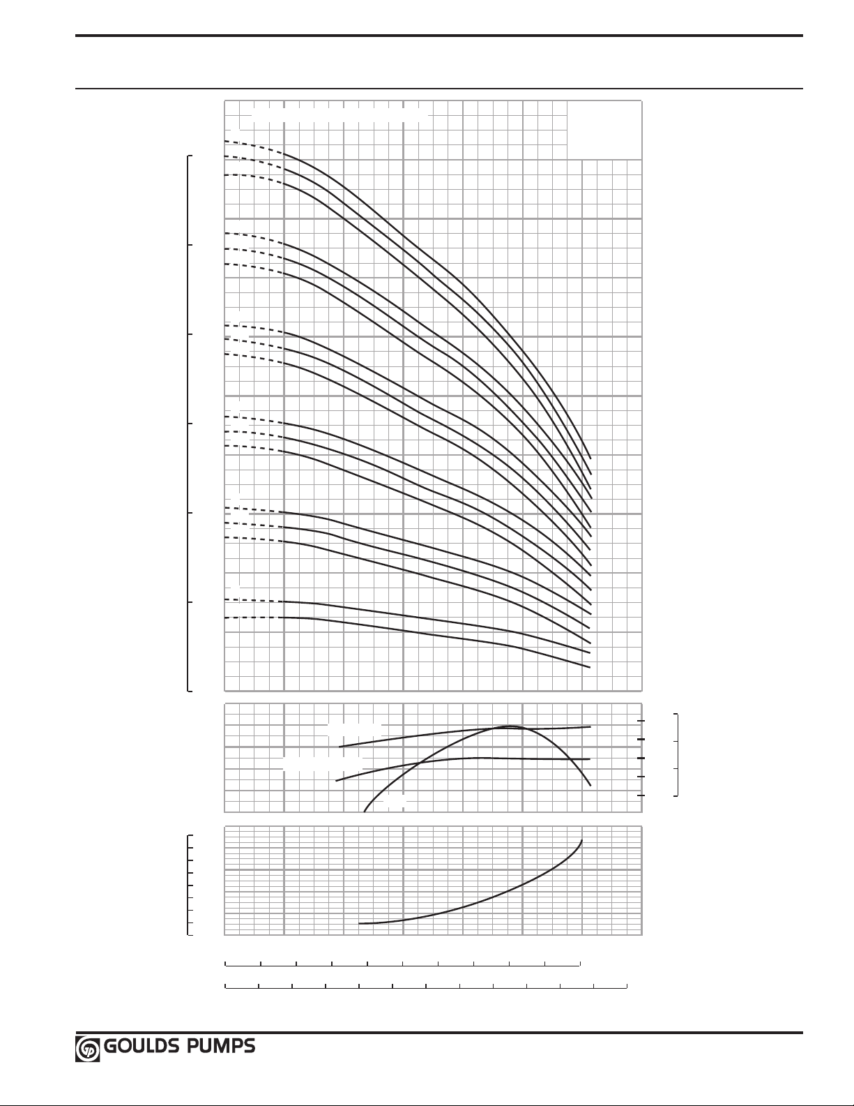
0
40
100
120
0 140
FEET
TOTAL DYNAMIC HEAD
60
65
85
EFF %
92SV 50 Hz
2900 RPM
kW/STAGE
0 2000
0
100
500
600
METERS
2
12
75
HP/STAGE
4
8
10
6
6
NPSHr
6
14
38
10
20 40
800600400200
3
4
5
6
7
400
300
200
8060
8
4
180016001400
180
160
140
80
60
20
120100
10
18
22
26
30
34
80
70
12001000
Q (m
3
/h)
Q (l/min)
(m)
(ft)
CAPACITY
0 400300200100
GPM
600500
TOTAL STAGES/REDUCED STAGES
6
6/1
6/2
5
5/1
5/2
4
4/1
4/2
3
3/1
3/2
2
2/1
2/2
1
1/1
FULL DIA.
REDUCED DIA.
Eff.
92SV Curve 2900 RPM
49
Page 52

Round Mating Flanges
Standard supply (included with pump)
• 1SV, 2SV and 3SV (SVA);
On request
• 1SV, 2SV and 3SV (versions SVB, SVC, SVD) oval flanges, threaded: kit containing 2 threaded mating flanges made of AISI 316 stainless steel
plus hardware and gaskets.
• SV33, 46, 66, 92 (SVB version): kit containing mating flanges (class 150 and class 300) threaded made of carbon steel.
Each kit contains 2 mating flanges plus hardware and gaskets.
• SV33, 46, 66, 92 (SVD versions): kit containing mating flanges (class 150 and class 300) threaded made of AISI 316 stainless steel.
Each kit contains 2 mating flanges plus hardware and gaskets.
Victaulic® Accessories (on request)
• 1, 2, 3 and 4SV version: kit containing 1 Victaulic® coupling with
AISI 316L stainless steel weld-on or threaded sleeve, plus EPDM or
viton o-ring gasket.
50
Page 53

Horizontal Mounting Option
F
E+L
1
D
C
B
A
FE+L
1
D
2 – 5⁄8" HOLES
2 – 5⁄8" HOLES
G
H
C
B
A
G
H
4 holes per chart
Flanges can be rotated 90º left or right.
4 holes per chart
Drain plug
Fill/vent plug
Discharge
Suction
A
• Available for all SSV sizes and all of their configurations.
• Consists of SSV pump with base mounting foot and footed motor for horizontal installations.
• Unit depicted may not show actual pump configuration. Use for mounting location only.
Not available
less motor.
Frame Hole Diameter
56
140
180
210
250
280
NOTE
Dimensions H and G are motor
foot dimensions.
Dimensions B and C are pump
foot dimensions.
11
⁄32
11
⁄32
13
⁄32
13
⁄32
17
⁄32
17
⁄32
Motor Pump
Series A B C D E F G H Shim Shim
Thickness Thickness
1SVA 56C 41⁄2 7 9 3⁄8 1 3 69⁄16 47⁄8 1 –
56C 41⁄2 7 9 13⁄8 1 3 69⁄16 47⁄8 1 –
1SVB/1SVD
184TC 41⁄2 7 9 13⁄8 1 51⁄2 85⁄8 71⁄2 – –
56C 41⁄2 101⁄2 12 13⁄8 1 3 69⁄16 47⁄8 1 –
1SVC
184TC 41⁄2 101⁄2 12 13⁄8 1 51⁄2 85⁄8 71⁄2 – –
56C 41⁄2 7 9 3⁄8 1 3 69⁄16 47⁄8 1 –
2SVA
184TC 41⁄2 7 9 3⁄8 1 51⁄2 85⁄8 71⁄2 – –
56C 41⁄2 7 9 13⁄8 1 3 69⁄16 47⁄8 1 –
2SVB/2SVD
184TC 41⁄2 7 9 13⁄8 1 51⁄2 85⁄8 71⁄2 – –
56C 41⁄2 101⁄2 12 13⁄8 1 3 69⁄16 47⁄8 1 –
2SVC
184TC 41⁄2 101⁄2 12 13⁄8 1 51⁄2 85⁄8 71⁄2 – –
56C 31⁄2 91⁄8 101⁄2 15⁄8 11⁄16 3 69⁄16 47⁄8 – –
3SVA
184TC 41⁄2 91⁄8 101⁄2 15⁄8 11⁄16 51⁄2 85⁄8 71⁄2 – –
56C 61⁄4 91⁄8 101⁄2 2 11⁄16 3 69⁄16 47⁄8 23⁄4 –
184TC 61⁄4 91⁄8 101⁄2 2 11⁄16 51⁄2 85⁄8 71⁄2 13⁄4 –
3SVB/3SVD 213TC 61⁄4 91⁄8 101⁄2 2 27⁄16 51⁄2 91⁄2 81⁄2 1 –
215TC 61⁄4 91⁄8 101⁄2 2 27⁄16 7 91⁄2 81⁄2 1 –
254TC 61⁄4 91⁄8 101⁄2 2 215⁄16 81⁄4 111⁄4 10 – –
184TCH 61⁄4 117⁄8 131⁄4 2 11⁄16 51⁄2 85⁄8 71⁄2 13⁄4 –
213TC 61⁄4 117⁄8 131⁄4 2 27⁄16 51⁄2 91⁄2 81⁄2 1 –
3SVC
215TC 61⁄4 117⁄8 131⁄4 2 27⁄16 7 91⁄2 81⁄2 1 –
254TC 61⁄4 117⁄8 131⁄4 2 215⁄16 81⁄4 111⁄4 10 – –
184TCH 61⁄4 91⁄8 101⁄2 2 11⁄16 51⁄2 85⁄8 71⁄2 13⁄4 –
213TC 61⁄4 91⁄8 101⁄2 2 27⁄16 51⁄2 91⁄2 81⁄2 1 –
4SVB/4SVD 215TC 61⁄4 91⁄8 101⁄2 2 27⁄16 7 91⁄2 81⁄2 1 –
254TC 61⁄4 91⁄8 101⁄2 2 215⁄16 81⁄4 111⁄4 10 – –
256TC 61⁄4 91⁄8 101⁄2 2 215⁄16 10 111⁄4 10 – –
184TCH 61⁄4 117⁄8 131⁄4 2 17⁄16 51⁄2 85⁄8 71⁄2 13⁄4 –
213TC 61⁄4 117⁄8 131⁄4 2 27⁄16 51⁄2 91⁄2 81⁄2 1 –
4SVC 215TC 61⁄4 117⁄8 131⁄4 2 27⁄16 7 91⁄2 81⁄2 1 –
254TC 61⁄4 117⁄8 131⁄4 2 215⁄16 81⁄4 111⁄4 10 – –
256TC 61⁄4 117⁄8 131⁄4 2 215⁄16 10 111⁄4 10 – –
Motor
Frame
For all other dimensions see dimensions and weights table.
All dimensions are in inches.
NOTE: L1 dimensions located on vertical version drawings.
51
Page 54

33SV – 92SV Horizontal Mounting Option
• Consists of SSV pump with base mounting foot and footed motor for horizontal installations.
• Unit depicted may not show actual pump configuration. Use for mounting location only.
16.50
(419)
9.13
(232)
5.00
(127)
7.25
(184)
6.25
(159)
Ø 5/8 (16)
3 HOLES
A & L1
F F
Ø H
11.00
(279)
8.00
(203)
Pump Frame A B E F G (ref.) H - Dia.
182TC
184TC 2.75
213TC
215TC 3.50
254TC
33SVB 256TC 1.75
33SVD 284TC 5.50 4.75
286TC 5.50
324TSC
326TSC 6.00
364TSC
365TSC 6.12
182TC
184TC 2.75
213TC
46SVB 215TC 3.50
46SVD 254TC
66SVB 256TC
66SVD 284TC
92SVB 286TC 5.50
92SVD 324TSC
326TSC 6.00
364TSC
365TSC 6.12
0.50 3.50
1.25 4.25
5.00
1.13
2.25 6.25
2.88 7.00
0.50 3.70
1.25 4.25
1.75
2.25 6.25
2.88 7.00
5.00
2.50
2.25
2.75
4.12
5.00
5.25
5.63
2.25
2.75
4.12
5.00
4.75
5.50
5.25
5.63
8.63
9.50
11.25
12.25
16.00
18.00
8.63
9.50
11.25
13.50
15.25
17.00
E
G
REF.
E
13/32
17/32
21/32
13/32
17/32
21/32
52
Page 55

Technical Data – Pump Hydraulics / Motor Sizing
1SV 3500 RPM
Number of Maximum Motor HP for use Motor HP for use Shutoff Shutoff
Stages HP With 1.15 SF With AQUAVAR TDH TDH MAWP Motor Rotation
Draw Motor (1.0 SF) (Feet) (Bar)
22 6.7 7.5 7.5 1100 32.8
20 6.1 7.5 7.5 1005 30.0 580 PSI (40 Bar) CCW
18 5.4 5 7.5 905 27.0
16 4.8 5 5 795 23.7
15 4.6 5 5 742 22.2
13 4 5 5 642 19.2
11 3.4 3 5 550 16.4
9 2.7 3 3 445 13.3
8 2.4 3 3 398 11.9 362 PSI (25 Bar) CW
7 2 2 2 350 10.4
6 1.8 2 2 300 9.0
5 1.5 1.5 1.5 250 7.5
4 1.1 1 1.5 200 6.0
3 0.9 3/4 1 142 4.2
2 0.6 1/2 3/4 100 3.0
2SV 3500 RPM
Number of Maximum Motor HP for use Motor HP for use Shutoff Shutoff
Stages HP With 1.15 SF With AQUAVAR TDH TDH MAWP Motor Rotation
Draw Motor (1.0 SF) (Feet) (Bar)
22 7.7 7.5 NA 950 28.4
20 6.8 7.5 7.5 860 25.7 580 PSI (40 Bar) CCW
18 6.2 7.5 7.5 760 22.7
16 5.3 5 7.5 726 21.7
15 4.9 5 5 680 20.3
13 4.6 5 5 595 17.8
11 4 5 5 500 14.9
9 3.3 3 5 407 12.2
8 2.9 3 3 360 10.7
7 2.4 3 3 315 9.4 362 PSI (25 Bar) CW
6 2.1 2 3 270 8.1
5 1.8 2 2 222 6.6
4 1.5 1.5 1.5 175 5.2
3 1.1 1 1.5 137 4.1
2 0.7 3/4 1 92 2.7
3SV 3500 RPM
Number of Maximum Motor HP for use Motor HP for use Shutoff Shutoff
Stages HP With 1.15 SF With AQUAVAR TDH TDH MAWP Motor Rotation
Draw Motor (1.0 SF) (Feet) (Bar)
16 17.6 20 20 1010 30.2
14 15 15 15 894 26.7
13 14 15 15 830 24.8
12 12.8 15 15 760 22.7
11 11.5 10 15 700 20.9
10 10.7 10 15 640 19.1
9 9.7 10 10 575 17.2
8 8.5 7.5 10 505 15.1
7 7.5 7.5 7.5 450 13.4
6 6.5 7.5 7.5 380 11.3
5 5.4 5 7.5 320 9.6
4 4.3 5 5 250 7.5
3 3.3 3 5 190 5.7
2 2.2 2 3 128 3.8
580 PSI (40 Bar) CCW
362 PSI (25 Bar) CW
53
Page 56

Technical Data – Pump Hydraulics / Motor Sizing
4SV 3500 RPM
Number of Maximum Motor HP for use Motor HP for use Shutoff Shutoff
Stages HP With 1.15 SF With AQUAVAR TDH TDH MAWP Motor Rotation
Draw Motor (1.0 SF) (Feet) (Bar)
12 26.4 25 NA 930 27.8 580 PSI (40 Bar) CCW
10 21.6 20 25 780 23.3
9 19.2 20 20 700 20.9
8 16.9 15 20 620 18.5
7 14.9 15 15 540 16.1
6 12.9 15 15 460 13.7 362 PSI (25 Bar) CW
5 10.7 10 15 390 11.6
4 8.6 7.5 10 305 9.1
3 6.3 7.5 7.5 228 6.8
2 4.3 5 5 150 4.5
33SV 3500 RPM
# of Impellers / Maximum HP Motor HP for use Motor HP for use Shutoff TDH Shutoff TDH Casing / Sleeve Stages requiring Pump Flange
# reduced Draw with 1.15 SF with Aquavar (Feet) (Bar) Pressure rating Thrust Balancing Rating
Diameter Motor (1.0 SF) (Standard Assy.) Piston
10 54.3 1125 34
10/2 52.8 60 1096 33
10/1 51.3
9 48.8 1012 30
9/1 47.4 983 29
9/2 45.9
8 43.4 900 27
8/1 41/9 871 26 Thrust Piston
8/2 40.5
7 38 787 23
7/1 36.5 758 23
7/2 35 40 729 22
6 32.6 576 20
6/1 31.1 30 646 19
6/2 29.6 617 18
5 27.1 30 562 17
5/1 25.7 25 533 16
5/2 24.2
4 21.7 450 13
4/1 20.2 20 421 13
4/2 18.8 20 392 12 25 Bar (362 PSI)
3 16.3 337 10 1
3/1 14.7 15 310 9
3/2 13.2 15 281 8 Class 125 / 150
2 10.9
2/1 9.4
2/2 7.9 7.5 167 5
1 5.4
1/1 4 5 84 3
1 Pump assembly may be modified for 40 bar (580 psi) application – contact factory.
1066 32
50
954 28
50
842 25 Required
40
504 15
25
225 7
10
7.5 113 3
5
196 6
10
40 Bar (580 PSI)
Class 250 / 300
54
Page 57

Technical Data – Pump Hydraulics / Motor Sizing
46SV 3500 RPM
# of Impellers / Maximum HP Motor HP for use Motor HP for use Shutoff TDH Shutoff TDH Casing / Sleeve Stages requiring Pump Flange
# reduced Draw with 1.15 SF with Aquavar (Feet) (Bar) Pressure rating Thrust Balancing Rating
Diameter Motor (1.0 SF) (Standard Assy.) Piston
10/2 77.8 1210 36.1
9 73.2
9/1 71.5 1111 33.2
9/2 69.7
8 65 1010 30.2
8/1 63.3
8/2 61.6 959 28.6 40 Bar (580 PSI)
7 56.9 884 26.4
7/1 55.2 60 858 25.6
7/2 53.4
6 48.8 758 22.6 Required
6/1 47.1 50 732 21.9
6/2 45.3 706 21.1
5 40.7
5/1 38.9
5/2 37.2 580 17.3
4 32.5 505 15.1
4/1 30.8 30
4/2 29 453 13.5
3 24.4 25 379 11.3
3/1 22.7
3/2 20.9 327 9.8
2 16.3 20 253 7.6
2/1 14/5 15
2/2 12.8 200 6.0
1 8.5 10 10 127 3.8
1/1 6.7 7.5 7.5 102 3.0
1137 33.9
75
1085 32.4
75
984 29.4
60
832 24.8 Thrust Piston Class 250 / 300
50
632 18.9
40
25 353 10.5
20
605 18.1
40
479 14.3
30
226 6.7
15
25 Bar (362 PSI)
1
Class 125 / 150
66SV 3500 RPM
# of Impellers / Maximum HP Motor HP for use Motor HP for use Shutoff TDH Shutoff TDH Casing / Sleeve Stages requiring Pump Flange
# reduced Draw with 1.15 SF with Aquavar (Feet) (Bar) Pressure rating Thrust Balancing Rating
Diameter Motor (1.0 SF) (Standard Assy.) Piston
6 73.2 850 25.4
6/1 70.2 75
6/2 67.2 796 23.8
5 61
5/1 58
5/2 55 655 19.6 Required
4 48.8 50 566 16.9
4/1 45.8 50 540 16.1
4/2 42.8
3 36.6
3/1 33.6
3/2 30.6 30 372 11.1
2 24.4 25
2/1 21.4
2/2 18.4 20 230 6.9
1 12.2 15 15 142 4.2
1/1 9.2 10 10 115 3.4
1 Pump assembly may be modified for 40 bar (580 psi) application – contact factory.
707 21.1
60
513 15.3
40
398 11.9
30
257 7.7
20
822 24.5 40 Bar (580 PSI)
75
681 20.3 Thrust Piston Class 250 / 300
60
424 12.7
40
283 8.4
25
25 Bar (362 PSI)
1
Class 125 / 150
55
Page 58

Technical Data – Pump Hydraulics / Motor Sizing
92SV 3500 RPM
# of Impellers / Maximum HP Motor HP for use Motor HP for use Shutoff TDH Shutoff TDH Casing / Sleeve Stages requiring Pump Flange
# reduced Draw with 1.15 SF with Aquavar (Feet) (Bar) Pressure rating Thrust Balancing Rating
Diameter Motor (1.0 SF) (Standard Assy.) Piston
5/1 73.8
5/2 70.3 75 707 21.1
4 61.9 605 18.1 Thrust Piston Class 250 / 300
4/1 58.3 60
4/2 54.8 556 16.6
3 46.5 50
3/1 42.9
3/2 39.4
2 31
2/1 27.4 30 278 8.3
2/2 23.4 25 25 253 7.6
1 15.5
1/1 12 15 127 3.8
1 Pump assembly may be modified for 40 bar (580 psi) application – contact factory.
732 21.9
75
580 17.3 Required
60
454 13.6
429 12.8 25 Bar (362 PSI)
40
305 9.1
30
20 151 4.5
15
50
405 12.1 1
40
Class 125 / 150
56
Page 59

Technical Data – Pump Hydraulics / Motor Sizing
1SV 2900 RPM
Number of Stages
Draw (Meters) (Bar)
24 3.72 5 258 25.0
22 3.41 237 23.2
20 3.10
18 2.79 194 19.0
16 2.48 172 16.8
14 2.17
12 1.86 130 12.7
11 1.71 118 11.6
9 1.40 1½ 97 9.5
8 1.24 87 8.5
7 1.09 1 75 7.3
6 0.93
5 0.78 54 5.3
4 0.62 43 4.2
3 0.47 ½ 33 3.2
2 0.31 23 2.3
2SV 2900 RPM
Number of Stages
Draw (Meters) (Bar)
24 4.80 242 23.7
22 4.40 5 222 21.7
20 4.00 202 19.8
18 3.60 182 17.8
16 3.20
14 2.80 142 13.9
13 2.60 132 12.9
11 2.20
9 1.80 92 9.0
8 1.60
7 1.40 72 7.1
6 1.20
5 1.00 52 5.1
4 0.80 ¾ 42 4.1
3 0.60
2 0.40 20 2.0
Maximum HP
Maximum HP
Motor HP
Motor HP
Shutoff TDH Shutoff TDH
217 21.3
3
152 14.9
2
65 6.4
¾
Shutoff TDH Shutoff TDH
162 15.9
3
112 11.0 362 PSI (25 Bar) CW
2
82 8.0
1½
62 6.1
1
32 3.1
½
MAWP Motor Rotation
362 PSI (25 Bar) CW
MAWP Motor Rotation
3SV 2900 RPM
Number of Stages
Draw (Meters) (Bar)
16 9.6 10 220 21.6
14 8.4 192 18.8
12 7.2 7½ 164 16.1
11 6.6 150 14.7
9 5.4 124 12.1
8 4.8 5 110 10.8 362 PSI (25 Bar) CW
6 3.6 82 8.0
5 3 3 68 6.7
4 2.4 2 55 5.4
3 1.8
2 1.2 28 2.7
NOTES:
½ – 1 HP = 1.25 S.F. @ 50 Hz.
1½ – 75 HP = 1.15 S.F. @ 50 Hz.
Maximum HP
Motor HP
Shutoff TDH Shutoff TDH
41 4.0
1½
MAWP Motor Rotation
57
Page 60

Technical Data – Pump Hydraulics / Motor Sizing
4SV 2900 RPM
Number of Stages
Draw (Meters) (Bar)
15 18 20 258 25.0
14 16.8 242 23.7
12 14.4 15 208 20.4
10 12 173 16.9
8 9.6 10 138 13.5
7 8.4 122 12.0 362 PSI (25 Bar) CW
6 7.2 7½ 104 10.2
5 6 86 8.4
4 4.8 5 68 6.7
3 3.6 3 53 5.2
2 2.3 2 35 3.4
33SV 2900 RPM
# of Impellers / Maximum HP Motor HP for use Shutoff TDH Shutoff TDH Casing / Sleeve Stages requiring Pump Flange
# reduced Draw with 1.15 SF (Feet) (Bar) Pressure rating Thrust Balancing Rating
Diameter Motor (@ 50 Hz) (Standard Assy.) Piston
10 32 750 22.4
10/1 30.5 30 731 21.8
10/2 29 712 21.3
9 28.8 675 20.2
9/1 27.3 656 19.6 Thrust Piston
9/2 25.8 25 637 19 Required Class 250 / 300
8 25.6 600 17.9
8/1 24.1 582 17.4
8/2 22.6 562 16.8
7 22.4 525 15.7
7/1 20.9
7/2 19.4 487 14.5
6 19.2 450 13.4
6/1 17.7 431 12.9
6/2 16.2 412 12.3 25 Bar (362 PSI)
5 16 376 11.2 1
5/1 14.5 15 356 10.6
5/2 13 337 10.1
4 12.8 300 9
4/1 11.3 281 8.4
4/2 9.8 10 262 7.8
3 9.6 225 6.7
3/1 8.1 206 6.2
3/2 6.6 7.5 187 5.6
2 6.4 150 4.5
2/1 4.9
2/2 3.5 111 3.3
1 3.2 3 75 2.2
1/1 1.7 2 56 1.7
1 Pump assembly may be modified for 40 bar (580 psi) application – contact factory.
Maximum HP
Motor HP
506 15.1
20
131 3.9
5
Shutoff TDH Shutoff TDH
MAWP Motor Rotation
Class 125 / 150
58
Page 61

Technical Data – Pump Hydraulics / Motor Sizing
46SV 2900 RPM
# of Impellers / Maximum HP Motor HP for use Shutoff TDH Shutoff TDH Casing / Sleeve Stages requiring Pump Flange
# reduced Draw with 1.15 SF (Feet) (Bar) Pressure rating Thrust Balancing Rating
Diameter Motor (@ 50 Hz) (Standard Assy.) Piston
10 45.9 256 7.6
10/1 44.1 251 7.5
10/2 42.4 246 7.3
9 41.3 40 231 6.9
9/1 39.6 225 6.7
9/2 37.8 220 6.6
8 36.7 205 6.1
8/1 35.0 200 6.0
8/2 33.3
7 32.0 180 5.4
7/1 30.3 174 5.2
7/2 28.6 169 5.0
6 27.5
6/1 25.7 148 4.4
6/2 24.0 143 4.3 25 Bar (362 PSI) Class 125 / 150
5 22.9 128 3.8 1
5/1 21.2
5/2 19.4 117 3.5
4 18.4 103 3.1
4/1 16.6 97 2.9
4/2 14.9
3 13.8 77 2.3
3/1 12.1 72 2.1
3/2 10.3
2 9.1 51 1.5
2/1 7.5 7.5 46 1.4
2/2 5.6 41 1.2
1 4.6 5 26 0.8
1/1 3.8 23 0.7
1 Pump assembly may be modified for 40 bar (580 psi) application – contact factory.
194 5.8
30
154 4.6
25
123 3.7
20
92 2.7
15
66 2.0
10
59
Page 62

Technical Data – Pump Hydraulics / Motor Sizing
66SV 2900 RPM
# of Impellers / Maximum HP Motor HP for use Shutoff TDH Shutoff TDH Casing / Sleeve Stages requiring Pump Flange
# reduced Draw with 1.15 SF (Feet) (Bar) Pressure rating Thrust Balancing Rating
Diameter Motor (@ 50 Hz) (Standard Assy.) Piston
6 41 564 16.8
6/1 39.1 40 545 16.3
6/2 37.3 528 15.8 Thrust Piston Class 250 / 300
5 34 469 14.0 Required
5/1 32.3 30 452 13.5
5/2 30.5 434 13.0
4 27.1 376 11.2
4/1 25.3 25 358 10.7
4/2 23.7 340 10.2 25 Bar (362 PSI)
3 20.5
3/1 18.7 264 7.9
3/2 16.9 246 7.3
2 13.6 15 188 5.6
2/1 11.9 170 5.1
2/2 10.1 10 152 4.5
1 6.8 7.5 94 2.8
1/1 5.1 5 76 2.3
92SV 2900 RPM
# of Impellers / Maximum HP Motor HP for use Shutoff TDH Shutoff TDH Casing / Sleeve Stages requiring Pump Flange
# reduced Draw with 1.15 SF (Feet) (Bar) Pressure rating Thrust Balancing Rating
Diameter Motor (@ 50 Hz) (Standard Assy.) Piston
6 53.3 610 18.21
6/1 51 50 594 17.73
6/2 48.7 577 17.23 Thrust Piston Class 250 / 300
5 44.4 509 15.20 Required
5/1 42.1
5/2 40 475 14.18
4 35.5 407 12.15
4/1 33.2
4/2 31 374 11.17 25 Bar (362 PSI)
3 26.6
3/1 24.3 289 8.63
3/2 22
2 17.8 204 6.09
2/1 15.5
2/2 13.1 171 5.11
1 9 10 102 3.05
1/1 6.8 7.5 85 2.54
1 Pump assembly may be modified for 40 bar (580 psi) application – contact factory.
282 8.4 1
20
492 14.69
40
390 11.64
30
305 9.11 1
25
272 8.12
20
187 5.58
15
Class 125 / 150
Class 125 / 150
Maximum Inlet Pressure
The following table shows the maximum permissible inlet
pressure. However, the actual inlet pressure + pressure
against a closed valve must always be lower than the
maximum permissible operating pressure.
(Refer to pressure/temperature curves on page 13 to verify
MAWP of pump)
Pump Number of Stages Max. Inlet Pressure
17-22 Stages
16-22 Stages
14-16 Stages
11-12 Stages
33SV 1-10 Stages
46SV 1-10 Stages
66SV 1-6 Stages
92SV 1-6 Stages
2-16 Stages
1SV
2-25 Stages
2SV
2-13 Stages
3SV
2-10 Stages
4SV
250 psi (17 bar)
60
Page 63

Technical Data – Water Property Chart
Temp ºF Temp ºC
(Cubic ft/lb) @ 39.2ºF @ 60ºF @ 68ºF (lb/cubic ft) (psi Abs)
32 0.0 0.01602 1.000 1.001 1.002 62.42 0.088
35 1.7 0.01602 1.000 1.001 1.002 62.42 0.100
40 4.4 0.01602 1.000 1.001 1.002 62.42 0.122
50 10.0 0.01603 0.999 1.001 1.002 62.38 0.178
60 15.6 0.01604 0.999 1.000 1.001 62.34 0.256
70 21.1 0.01606 0.998 0.999 1.000 62.27 0.363
80 26.7 0.01608 0.996 0.998 0.999 62.19 0.507
90 32.2 0.0161 0.995 0.996 0.997 62.11 0.698
100 37.8 0.01613 0.993 0.994 0.995 62.00 0.949
120 48.9 0.0162 0.989 0.990 0.991 61.73 1.692
140 60.0 0.01629 0.983 0.985 0.986 61.39 2.889
160 71.1 0.01639 0.977 0.979 0.979 61.01 4.741
180 82.2 0.01651 0.970 0.972 0.973 60.57 7.510
200 93.3 0.01663 0.963 0.964 0.966 60.13 11.526
212 100.0 0.01672 0.958 0.959 0.960 59.81 14.696
220 104.4 0.01677 0.955 0.956 0.957 59.63 17.186
240 115.6 0.01692 0.947 0.948 0.949 59.10 24.97
260 126.7 0.01709 0.938 0.939 0.940 58.51 35.43
280 137.8 0.01726 0.928 0.929 0.930 58.00 49.20
300 148.9 0.01745 0.918 0.919 0.920 57.31 67.01
320 160.0 0.01756 0.908 0.909 0.910 56.66 89.66
340 171.1 0.01787 0.896 0.898 0.899 55.96 118.01
360 182.2 0.01811 0.885 0.886 0.887 55.22 153.04
380 193.3 0.01836 0.873 0.874 0.875 54.47 195.77
400 204.4 0.01864 0.859 0.860 0.862 53.65 247.31
420 215.6 0.01894 0.846 0.847 0.848 52.80 308.83
440 226.7 0.01926 0.832 0.833 0.834 51.92 381.59
460 237.8 0.0196 0.817 0.818 0.819 51.02 466.9
480 248.9 0.02 0.801 0.802 0.803 50.00 566.1
500 260.0 0.0204 0.785 0.786 0.787 49.02 680.8
520 271.1 0.0209 0.765 0.766 0.767 47.85 812.4
540 282.2 0.0215 0.746 0.747 0.748 46.51 962.5
560 293.3 0.0221 0.726 0.727 0.728 45.30 1133.1
580 304.4 0.0228 0.703 0.704 0.704 43.90 1325.8
600 315.6 0.0236 0.678 0.679 0.680 42.30 1542.9
620 326.7 0.0247 0.649 0.650 0.650 40.50 1786.6
640 337.8 0.026 0.617 0.618 0.618 38.50 2059.7
660 348.9 0.0278 0.577 0.577 0.578 36.00 2365.4
680 360.0 0.0305 0.525 0.526 0.527 32.80 2708.1
700 371.1 0.0369 0.434 0.435 0.435 27.10 3093.7
Specific Volume Specific Gravity Weight Vapor Pressure
61
Page 64

Technical Data – NPSH
NPSH
The minimum operating values that can be reached at the pump
suction end are limited by the onset of cavitation.
Cavitation is the formation of vapor-filled cavities within liquids
where the pressure is locally reduced to a critical value, or where
the local pressure is equal to, or just below the vapor pressure of
the liquid.
The vapor-filled cavities flow with the current and when they
reach a higher pressure ares the vapor contained in the cavities
condenses. The cavities collide, generating pressure waves that
are transmitted to the walls. These, being subjected to stress
cycles, gradually become deformed and yield due to fatigue. This
phenomenon, characterized by a metallic noise produced by the
hammering on the pipe walls, is called incipient cavitation.
The damage caused by cavitation may be magnified by electrochemical corrosion and a local rise in temperature due to the plastic deformation of the walls. The materials that offer the highest
resistance to heat and corrosion are alloy steels, especially austenitic steel. The conditions that trigger cavitation may be assessed
by calculating the total net suction head, referred to in technical
literature with the acronym NPSH (Net Positive Suction Head).
The NPSH represents the total energy (expressed in feet) of the
liquid measured at suction under conditions of incipient cavitation, excluding the vapor pressure (expressed in feet) that the
liquid has at the pump inlet.
The maximum possible suction head for installation depends on
the value of the atmospheric pressure (i.e. the elevation above
sea level at which the pump is installed) and the temperature of
the liquid.
To help the user, with reference to water temperature (40ºF) and
to the elevation above sea level, the following tables show the
drop in hydraulic pressure head in relation to the elevation above
sea level, and the suction loss in relation to temperature.
Water Temperature (ºF) 68 104 140 176 194 230 248
Suction Loss (ft) -.7 2.3 6.6 16.4 24.3 50.5 70.5
Elevation Above Sea Level (ft) 1600 3300 4900 6500 8200 9800
Suction Loss (ft) 1.8 3.6 5.4 7.2 9.0 10.8
To reduce it to a minimum, especially in cases of high suction
head (over 13 – 16 feet) or within the operating limits with high
flow rates, we recommend using a suction line having a larger
diameter than that of the pump’s suction port. It is always a good
idea to position the pump as close as possible to the liquid to be
pumped.
To find the static height (hz) at which to install the machine under
safe conditions, the following formula must be verified:
hp + hz ≥ (NPSHr + 2 ft) + hf + hpv
where:
hp is the absolute pressure applied to the free liquid surface in
the suction tank, expressed in feet of liquid; hp is the
quotient between the barometric pressure and the specific
weight of the liquid.
hz is the suction lift between the pump axis and the free liquid
surface in the suction tank, expressed in feet; hz is negative
when the liquid level is lower than the pump axis.
hf is the flow resistance in the suction line and its accessories,
such as: fittings, foot valve, gate valve, elbows, etc.
hpv is the vapor pressure of the liquid at the operating
temperature, expressed in feet of the liquid. hpv is the
quotient between the Pv vapor pressure and the liquid‘s
specific weight.
0.5 is the safety factor.
62
Page 65

Technical Data – Compatability Chart for Materials
in Contact with Most Commonly Used Liquids
(%) Min/Max ºF Weight (lb/in3) 304 316 CI/316 316 Seal
Water 100 23/248 • • • • Q1BEGG E
Deionized, demineralized
or distilled water
Water and oil emulsion any 23/194 • • • • Q1BVGG V
Acetic acid (•) 80 14/158 .038 • • • • Q1BEGG E
Citric acid 5 14/158 .056 • • • • Q1BEGG E
Hydrochloric acid 2 23/77 .043 • • Q1Q1VGG V
Phosphoric acid 10 23/86 .048 • • Q1BEGG E
Nitric acid (•) 50 23/86 .053 • • • • Q1Q1VGG V
Sulphuric acid (•) 2 14/77 .066 • • Q1BVGG V
Tannic acid 20 32/122 • • Q1BEGG E
Tartaric acid 50 14/77 .063 • • • • Q1Q1VGG V
Uric acid 80 14/176 .068 • • • • Q1BEGG E
Benzoic acid 70 32/158 .047 • • • • Q1BVGG V
Boric acid Saturated 14/194 .052 • • • • Q1Q1VGG V
Formic acid (•) 5 5/77 .044 • • • • Q1BEGG E
Ethyl alcohol (•) 100 23/104 .029 • • • • Q1BEGG E
Methyl alcohol (•) 100 23/104 .029 • • • • Q1BEGG E
Propyl alcohol (•) 100 23/176 .029 • • • • Q1BEGG E
Butyl alcohol 100 23/176 .030 • • • • Q1BVGG V
Denatured alcohol (•) 100 23/158 .030 • • • • Q1BEGG E
Ammonia in water (•) 25 -4/122 .038 • • • • Q1BEGG E
Chloroform 14/86 .053 • • • • Q1BVGG V
Caustic soda 25 32/158 .077 • • • • Q1Q1EGG E
Water, detergents, mineral
oils mixture
Cleaning products 23/212 • • • • Q1Q1VGG V
Diesel oil (•) 100 32/176 .033 • • • • Q1BVGG V
Kerosene (•) 100 32/176 • • • • Q1BVGG V
Fuel oil (•) 32/194 .027 • • • • Q1BVGG V
Glycerine 100 68/194 .046 • • • • Q1BEGG E
Sodium Hypochlorite 1 14/77 • • Q1Q1VGG V
Phosphates/polyphosphates 23/194 • • Q1Q1VGG V
Sodium nitrate Saturated 14/176 .081 • • • • Q1BEGG E
Cutting fluid 100 23/230 .033 • • • • Q1BVGG V
Peanut oil (•) 100 23/230 .034 • • • • Q1BEGG E
Colza oil (•) 100 23/230 .034 • • • • Q1BEGG E
Linseed oil (•) 100 23/230 .034 • • • • Q1BEGG E
Coconut oil (•) 100 -4/194 .033 • • • • Q1BEGG E
Soybean oil (•) 100 32/194 • • • • Q1BEGG E
Diathermic oil 100 23/230 .033 • • • • Q1BVGG V
Hydraulic oil 100 23/230 • • • • Q1BVGG V
Mineral oil 100 23/230 .034 • • • • Q1BVGG V
Sodium sulfate 15 14/104 .094 • • • • Q1Q1EGG E
Aluminum sulfate 30 23/122 .097 • • Q1Q1EGG E
Ammonium sulfate 10 14/140 .064 • • Q1Q1EGG E
Iron sulfate 10 23/86 .076 • • Q1BEGG E
Copper sulfate 20 32/86 .082 • • Q1Q1VGG V
Trichloroethylene 14/104 .053 • • • • Q1BVGG V
Perchlorethylene 14/86 .057 • • • • Q1BVGG V
Legend
Q1 = Silicon carbide
B = Impregnated carbon
E = EPDM
V = Viton
G = AISI 316 (spring, metal components)
(•) A special version may be necessary for this fluid. For additional information, please contact our sales network.
Concentration Temperature Specific SV 2, 4, 8, 16 SV 33, 46, 66, 92 Recommended Elastomers
Liquid
100 -13/230 • • • • Q1BEGG E
23/176
• • • • Q1Q1VGG V
63
Page 66

NOTES65NOTES
64
Page 67

Page 68

Goulds Pumps is a brand of ITT Water Technology, Inc. –
a subsidiary of ITT Industries, Inc.
Goulds Pumps, G&L Pumps, Aquavar and the
ITT Engineered Blocks Symbol are registered
trademarks and tradenames of ITT Industries.
© 2005 ITT Water Technology, Inc.
Printed in USA
GLSSV2
Goulds Pumps
1 Goulds Drive
Auburn, NY 13021
 Loading...