


WFAU
Whirlpool WFAU, WFLU, WFAR, WFLR, WFAT Installation Instructions Manual
...
80% GAS FURNACE INSTALLATION INSTRUCTIONS
Table of Contents
GAS FURNACE SAFETY................................................................1
INSTALLATION REQUIREMENTS................................................3
Tools and Parts ............................................................................3
Location Requirements................................................................3
Installation Configurations ...........................................................4
Duct Work Requirements.............................................................6
Electrical Requirements ...............................................................6
Gas Supply Requirements...........................................................6
Venting Requirements..................................................................6
INSTALLATION INSTRUCTIONS..................................................8
Inspect Shipment......................................................................... 8
Plan Vent System.........................................................................8
Connect Venting.........................................................................11
Install Duct Work ........................................................................11
Filter Specifications....................................................................11
Make Electrical Connections .....................................................12
Make Gas Connections..............................................................13
Check the Furnace Input Rate ...................................................13
Adjust the Furnace Input Rate ...................................................14
Complete Installation..................................................................15
Sequence of Operation ..............................................................16
Controls ......................................................................................16
TROUBLESHOOTING ..................................................................17
ASSISTANCE OR SERVICE.........................................................20
Accessories ................................................................................20
GAS FURNACE SAFETY
Your safety and the safety of others are very important.
We have provided many important safety messages in this manual and on your appliance. Always read and obey all
safety messages.
This is the safety alert symbol.
This symbol alerts you to potential hazards that can kill or hurt you and others.
All safety messages will follow the safety alert symbol and either the word “DANGER” or
“WARNING.” These words mean:
You can be killed or seriously injured if you don't
immediately follow instructions.
can be killed or seriously injured if you don't
You
follow instructions.
All safety messages will tell you what the potential hazard is, tell you how to reduce the chance of injury, and tell you
what can
Models WFAU, WFAR, WFAT
46924D003
happen if the instructions are not followed.
WFLU, WFLR, WFLT
Whirlpool® Home Cooling and Heating
7901 S.W. 6th Court
Plantation, Florida 33324

IMPORTANT SAFETY INSTRUCTIONS
■ Use only with type of gas approved for this furnace.
Refer to the furnace rating plate.
■ Install this furnace only in a location and position as
specified in the Location Requirements section of
these instructions.
■ Provide adequate combustion and ventilation air to the
furnace space as specified in the “Venting
Requirements” section of these instructions.
■ Combustion products must be discharged outdoors.
Connect this furnace to an approved vent system
only, as specified in the “Venting Requirements”
section of these instructions.
■ Never test for gas leaks with an open flame. Use a
commercially available soap solution made
specifically for the detection of leaks to check all
connections, as specified in the “Make Gas
Connections” section of these instructions.
■ Always install furnace to operate within the furnace’s
intended temperature-rise range with a duct system
which has an external static pressure within the
allowable range, as specified in the “Complete
Installation” section of these instructions. See furnace
rating plate.
SAVE THESE INSTRUCTIONS
■ When a furnace is installed so that supply ducts carry
air circulated by the furnace to areas outside the
space containing the furnace, the return air shall also
be handled by duct(s) sealed to the furnace casing
and terminating outside the space containing the
furnace.
■ A gas-fired furnace for installation in a residential
garage must be installed as specified in the “Location
Requirements” section of these instructions.
■ The furnace is not to be used for temporary heating of
buildings or structures under construction.
■ The furnace shall be installed so the electrical
components are protected from water.
■ Furnaces for indoor installation on combustible
flooring shall not be installed directly on carpeting, tile
or other combustible material other than wood
flooring.
The California Safe Drinking Water and Toxic Enforcement Act requires the Governor of California to publish a list
of substances known to the State of California to cause cancer, birth defects, or other reproductive harm, and
requires businesses to warn of potential exposure to such substances.
WARNING: This product contains a chemical known to the State of California to cause cancer, birth defects, or
other reproductive harm.
This appliance can cause low-level exposure to some of the substances listed, including benzene, formaldehyde,
carbon monoxide, toluene, and soot.
ADDITIONAL SAFETY INFORMATION
In the State of Massachusetts, the following installation instructions apply:
■
Installations and repairs must be performed by a qualified or licensed contractor, plumber, or gasfitter qualified or
licensed by the State of Massachusetts.
■
If using a ball valve, it shall be a T-handle type.
■
A flexible gas connector, when used, must not exceed 3 feet.
2
INSTALLATION
REQUIREMENTS
These instructions are intended as a general guide only for use by
qualified persons and do not supersede any national or local
codes in any way. Compliance with all local, state, or national
codes pertaining to this type of equipment should be determined
prior to installation.
Read this entire instruction manual, as well as the instructions
supplied in separate equipment, before starting the installation.
The installation of the furnace, wiring, warm air ducts, venting,
etc. must conform to the requirements of the National Fire
Protection Association; the National Fuel Gas Code, ANSI
Z223.1/NFPA No. 54 (latest edition) and the National Electrical
Code, ANSI/NFPA No. 70 (latest edition) in the United States, and
any state laws, local ordinances (including plumbing or
wastewater codes), or local gas utility requirements. Local
authorities having jurisdiction should be consulted before
installation is made. Such applicable regulations or requirements
take precedence over the general instructions in this manual.
This furnace is design certified by CSA International as a
Category I furnace using air from inside the structure for
combustion. The combustion system is fan-assisted, which
means it is equipped with an integral mechanical means to draw
products of combustion through the heat exchanger.
Location Requirements
Explosion Hazard
Keep flammable materials and vapors, such as
gasoline, away from furnace.
Place furnace so that burners are at least 18 inches
(46 cm) above the floor for a garage installation.
Failure to follow these instructions can result in death,
explosion, or fire.
Tools and Parts
Assemble the required tools before starting installation. Read and
follow the instructions provided with any tools listed here.
Tools Needed:
■ Pipe wrench
■ Screwdriver
■ Tape measure
■ Thread sealant
Parts Needed:
Check local codes and with gas supplier. Check existing gas
supply, electrical supply, and venting, and read “Duct Work
Requirements,” “Electrical Requirements,” “Gas Supply
Requirements” and “Venting Requirements” before purchasing
parts.
■ Non-corrosive leak check solution
■ Test g a uge wi t h ¹⁄₈ in. NPT
connection
(for measuring gas supply pressure)
Explosion Hazard
Do not install this furnace in a mobile home.
Doing so can result in death, explosion, fire, or
carbon monoxide poisoning.
IMPORTANT: Do not use the furnace as a heater in a building
under construction. The furnace can be severely damaged due to
the abnormal environment caused by construction. Chlorides
from sources such as paint, stain, or varnish; tile and counter
cements; adhesives; and foam insulation are abundant in a
structure under construction and can be highly corrosive. Low
return air temperature can cause condensation in the furnace and
other damage that can shorten the life of the furnace.
■ The furnace is suitable for installation in buildings
constructed on site. The furnace should be centralized in
respect to the heat distribution system as much as
practicable.
■ All models are suitable for closet or utility room installation.
Utility room installation requires:
A door opening large enough for the widest part of the
furnace.
A door opening large enough to remove/replace any other
appliance located in the utility room, such as a water heater.
Any other appliances arranged so that each appliance can be
removed/replaced without disturbing the furnace.
3
■ In a residential garage, a gas-fired furnace must be installed
so the burner(s) and the ignition source are located not less
than 18 in. above the floor. The furnace is to be located or
protected to avoid physical damage by vehicles.
■ WFAR, WFLR, WFAT, and WFLT models may be installed as
suspended units in the horizontal position. These furnaces
are not designed for direct attachment of suspension rods to
the furnace casing. See the “Installation Configurations”
section.
■ If the furnace is to be installed in an attic or other insulated
space, it must be kept free and clear of insulating materials.
Installation Clearances
■ A 2 in. minimum clearance is required in front for air openings
into the combustion chamber.
■ All servicing and cleaning of the furnace can be performed
from the front. If installed in a closet or utility room, provide 24
in. clearance in front for service if the door to the room is not
in line with the front of the furnace. Where servicing
clearances are greater than clearances to combustibles,
servicing clearances take precedence.
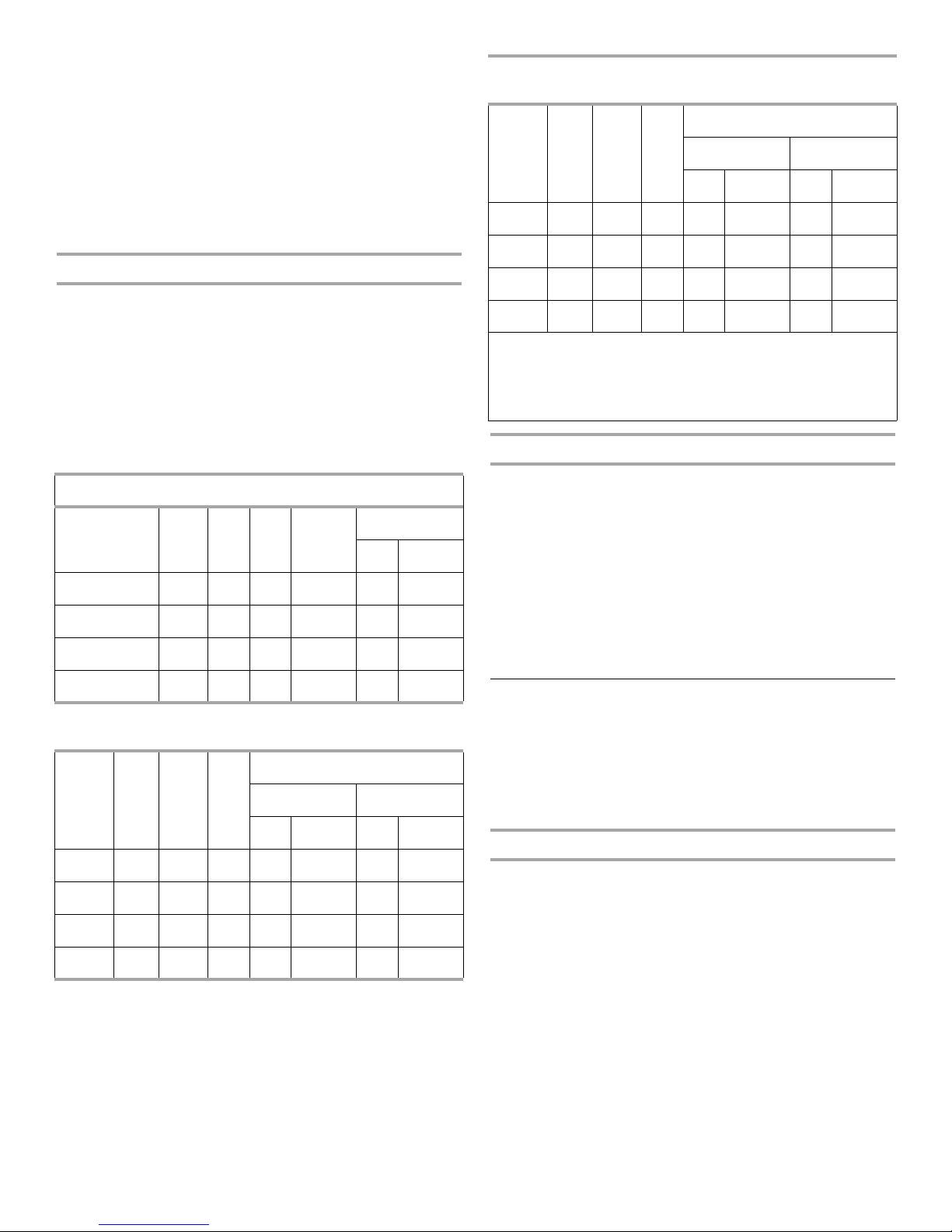
Minimum Clearance to Combustibles Chart
(all measurements in inches)
Upflow and Counterflow Installations
Cabinet
Width
14.5 4
17.5 4
21.0 4
24.5 4
Front Back Top Vent
1
01 623
1
01 622
1
01 6200
1
01 6200
Horizontal Installations
(Models WFAT and WFLT only)
Cabinet
Width Front Back Vent
14.5 4
17.5 4
21.0 4
24.5 4
1
0623
1
0622
1
0621010
1
0621010
Airflow
R to L L to R
Top Bottom Top Bottom
2
2
013
012
Sides
Left Right
3
3
0
0
2
2
Horizontal Installations
(Models WFAR and WFLR only)
Airflow
Cabinet
Width Front Back Vent
R to L L to R
Top Bottom Top Bottom
14.5 4
17.5 4
21.0 4
24.5 4
1
May be 2" when Type B-1 vent pipe is used.
2
May be 1" when Type B-1 vent pipe is used.
3
Where values greater than 0 are shown, may be 0" when Type
1
0621313
1
0621222
1
0621010
1
0621010
1
2
0
0
B-1 vent pipe is used.
High Altitude Installations
■ This furnace is approved for operation at altitudes from 0 to
4,500 feet above sea level without any required modifications.
■ From 4,500 to 7,500 ft, the gas manifold pressure needs to be
adjusted according to the information shown in the Manifold
Pressure vs. Altitude charts.
IMPORTANT:
For installations above 7,500 ft, the furnace input rate is to be
reduced per the requirements of the National Fuel Gas Code
(ANSI Z223.1/NFPA 54, latest edition), at the rate of 4 percent for
each 1,000 feet above sea level.
The furnace is not recommended for installation above 10,000 ft.
Installation Configurations
Models WFAU and WFLU must be installed only as an upflow
furnace. Models WFAT and WFLT may be installed as an upflow
or horizontal furnace. Models WFAR and WFLR may be installed
as either a counterflow or a horizontal furnace.
Models WFAR, WFLR, WFAT and WFLT furnaces can be
horizontally installed for airflow right to left or left to right.
Upflow Installations
WFAU, WFLU, WFAT and WFLT model furnaces can be installed
with either a side or bottom air return. For bottom air return the
bottom air return knockout plate must be removed. For units that
do not include a side or bottom return filter rack, kit no.
AFILT524-1 (side return) or kit no. AFILT529-1 (bottom return) can
be used.
To provide sufficient filter area for installations requiring more
than 1600 CFM nominal air delivery, return air will have to be
brought through both sides of the furnace, or through one side
and the bottom, or an optional filter rack WAFILTHA7 may be
used.
4
Horizontal Installations
WFAR, WFLR, WFAT and WFLT model furnaces can be
horizontally installed for airflow right to left or left to right. To
ensure access to parts for servicing, install upflow and
counterflow furnaces so that the burner and blower access
panels are readily accessible.
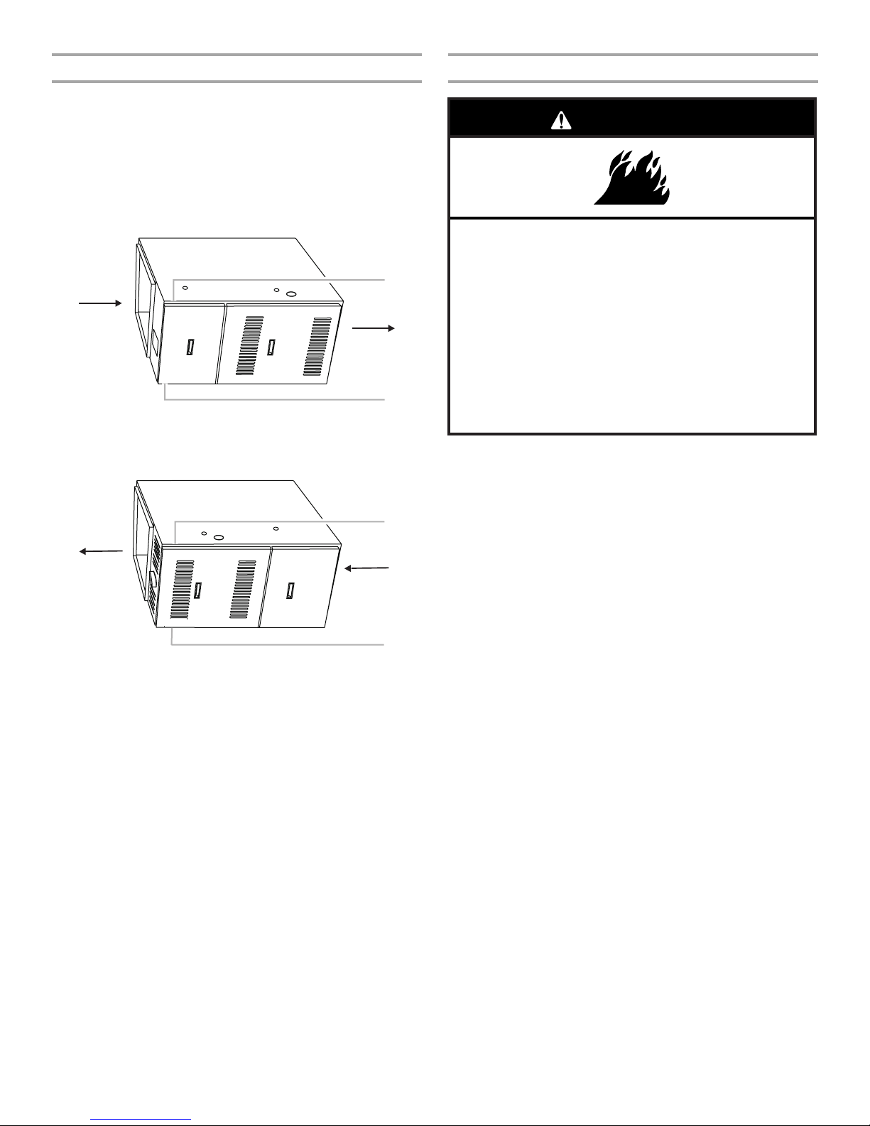
NOTE: When installed horizontally, the installer must install a
sheet metal screw to retain the upper door as shown following, in
either Position 1 or 2, depending on installation configuration.
Horizontal Installation (WFAR and WFLR models)
Return
1
Supply
Installation for Counterflow (Downflow) Models
WARNING
Fire Hazard
Before installing counterflow (downflow) furnace on
combustible surface, such as wood, install one of the
following kits:
WABASE 511 (14.5" cabinets)
WABASE 512 (17.5" cabinets)
WABASE 568 (21" cabinets)
WABASE 569 (24.5" cabinets)
2
1. Screw placement for Left to Right airflow
2. Screw placement for Right to Left airflow
Horizontal Installation (WFAT and WFLT models)
1
Supply
Return
2
1. Screw placement for Right to Left airflow
2. Screw placement for Left to Right airflow
Horizontal Installation - Suspended
WFAR, WFLR, WFAT and WFLT model furnaces may be installed
as suspended units in the horizontal position. These furnaces are
not designed for direct attachment of suspension rods to the
furnace casing.
■ The suspending means must be field fabricated, and should
consist of two “cradles” made by attaching two rods to a
length of angle iron or suitable gauge steel.
■ Locate the cradles so that they are as close as possible to the
ends of the furnace (this will provide access for removal of
major components such as the blower assembly).
■ Provide enough clearance between the suspension rods and
the furnace to allow removal of access panels.
Contact your local dealer.
Failure to do so can result in death or fire.
IMPORTANT:
■ The furnace may be installed directly on the supply plenum or
coil cabinet if the furnace is installed on a non-combustible
floor.
■ For installations on combustible flooring, a special base must
be ordered and used. See the “Accessories” section.
1. Cut, size and frame opening in floor to fit the Combustible
floor base and provide a minimum 1in. clearance between the
Supply Duct and combustible materials. The 4 legs on the
base assembly should recess into the floor, and the base
should rest on all 4 outside flanges.
2. Construct duct connections with 1in. to 1³⁄₄ in. right angle
flanges, and long enough to extend below the floor joists.
3. Drop the duct connections through the top of the base
assembly with the right angle flanges in good contact with
the glass tape on top of the base assembly.
4. Carefully position the furnace over the right angle duct
flanges.
5

Combustible Floor Installation (Counterflow Models only)
1
2
3
4
5
6
■ In all instances, other than wiring for the thermostat, the
wiring to be done and any replacement of wire shall conform
with the temperature limitation for Type T wire – 63°F (35°C)
rise.
■ The line voltage supply should be routed through a readily
accessible disconnect located within sight of the furnace. A
junction box on the furnace side panel is provided for line
voltage connections. See the furnace wiring diagram for
specific connection information.
■ Proper polarity of the supply connections (“HOT” and
“NEUTRAL”) must be observed to ensure that safety controls
provide the protection intended.
Gas Supply Requirements
This furnace is equipped for use with natural gas. A conversion
kit is required for use with propane. To order the correct
conversion kit, see “Accessories.”
■ Gas supply piping should be installed in accordance with
local codes and the regulations of the utility. Piping must be
of adequate size to prevent undue pressure drop. Consult the
local utility or gas supplier for complete details on special
requirements for sizing gas piping.
■ If local codes allow the use of a flexible gas appliance
connector, always use a new listed connector. Do not use a
connector which has previously serviced another gas
appliance.
1. Furnace
2. Woven glass tape (between
flanges of outlet duct and
base assembly)
3. Base assembly
4. Combustible flooring
5. Leg
6. Supply plenum or coil cabinet
(not provided - accessory)
Duct Work Requirements
Install the conditioned air plenum, ducts and air filters (if not
provided on the furnace) in accordance with NFPA 90B Standard
for the Installation of Warm Air Heating and Air-Conditioning
Systems (latest edition).
The furnace is provided with flanges for the connection of the
plenum and ducts.
All air filters must be listed as Class 2 furnace air filters.
Electrical Requirements
WARNING
Venting Requirements
Adequate provisions for combustion air and ventilation of furnace
must be made. Refer to Section 5.3, “Air for Combustion and
Ventilation,” of the National Fuel Gas Code, ANSI Z223.1/NFPA54
(latest edition), or applicable provisions of the local building
codes. For Category 1 furnaces, vent installations shall be in
accordance with parts 7 and 11 of the National Fuel Gas Code,
ANSI Z223.1/NFPA 54, the local building codes, and the furnace
and vent manufacturer’s instructions.
Unconfined Space
An unconfined space is defined as “a space whose volume is
more than 50 cu ft per 1000 BTU per hour of the combined input
rating of all appliances installed in that space.”
When a furnace is installed in an unconfined space in a building,
it can be assumed that the infiltration will be sufficient to supply
the required air.
If the furnace is installed in a ventilated attic or crawl space, it is
assumed that the air infiltration is sufficient to supply the required
combustion air. However, in a building of unusually tight
construction, additional outdoor air should be provided.
Confined Space
A confined space is defined as “a space whose volume is less
than 50 cu ft per 1000 BTU per hour of the combined input rating
of all appliances installed in that space.”
Confined Space Installation/Air from Inside Structure
Electrical Shock Hazard
Electrically ground furnace.
Connect ground wire to green ground screw.
Failure to do so can result in death or electrical shock.
■ The furnace must be grounded and wired in accordance with
local codes or, in the absence of local codes, with the
National Electrical Code ANSI/NFPA No. 70 (latest edition).
6
If the furnace is installed in a confined space within the building
and combustion air is taken from a heated space, the
combustion air and ventilating air must enter and leave the space
through two permanent openings of equal area. One opening
shall be located within 12 in. of the ceiling and the other within 12
in. of the floor.
NOTE: Each opening must have a free area of at least 1 square
inch per 1000 BTU/HR of total input rating of all equipment in the
enclosure, and not less than 100 square inches each.
 Loading...