

Page 1
Watson-Marlow Bredel E-Manuals
Search manual for ...
Go
WATSON-MARLOW BREDEL E-MANUALS
PB0275GB03
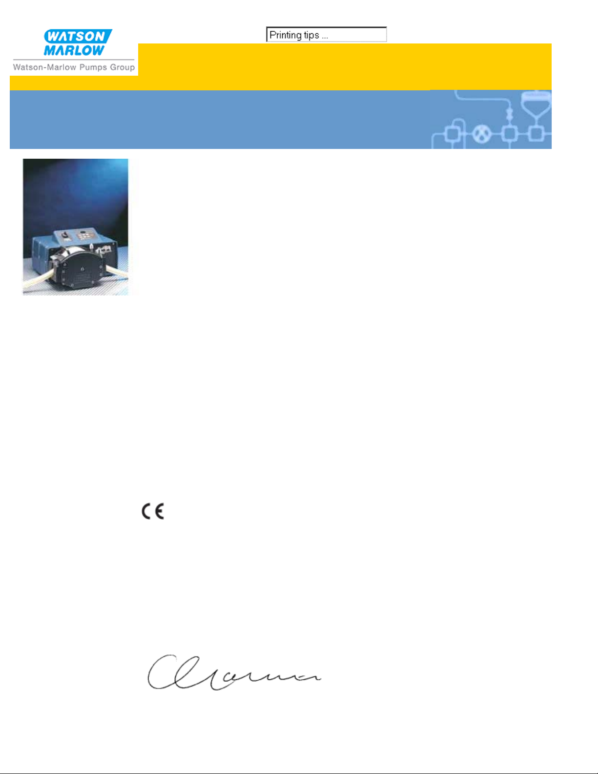
Watson-Marlow 704U, 704S
Clickable index
Contents
1. Declaration of conformity
2. Declaration of incorporation
3. Warranty
4. Information for returning pumps
5. Safety
6. Recommended operating
procedures
7. Installation
8. Troubleshooting
9. 704S and 704U Manual
operation
10. 704U Automatic operation
11. 704U Calibration procedure
12. Remote auto-manual switch and
TTL option
13. Guard safety warnings
14. Error messages
15. Care and maintenance
16. Specification
Double clicking anywhere in the manual will take you back to this index.
17. 701R, 701RX, 701RG, 701RE, 701REX
Pumphead installation
18. Tube loading
19. Fitting an extension pumphead
20. Pumphead spares: continuous tubing
21. Pumphead spares: tubing elements
22. Pumphead spares: rotor
23. Drive spares
24. Flow rates
25. 701R product codes
26. Flow, pressure and suction
27. Maximum peak working pressure ratings
28. Outline Dimensions
29. Trademarks and disclaimer
30. Warning not to use pumps in patientconnected applications
31. Publication history
32. Decontamination certificate
1 Declaration of conformity
When this pump unit is used as a stand alone pump it complies with: Machinery
Directive 98/37/EC EN60204-1, Low Voltage Directive 73/23/EEC EN61010-1, EMC
Directive 89/336/EEC, EN50081-1/EN50082-1.
2 Declaration of incorporation
When this pump unit is to be installed into a machine or is to be assembled with other
machines for installations, it must not be put into service until the relevant machinery has
been declared in conformity with the Machinery Directive 98/37/EC EN60204-1.
Responsible person: Christopher Gadsden, Managing Director, Watson-Marlow Limited,
Falmouth, Cornwall TR11 4RU, England. Telephone +44 (0) 1326 370370 Fax +44 (0)
1326 376009.
3 Two year warranty
http://www.watson-marlow.it/pdfs-global/m-704su-gb-03.htm[10/07/2012 14:21:14]
Page 2

Watson-Marlow Bredel E-Manuals
Watson-Marlow Limited warrants, subject to the conditions below, through either Watson-
Marlow Limited, its subsidiaries, or its authorised distributors, to repair or replace free of
charge, including labour, any part of this product which fails within two years of delivery of
the product to the end user. Such failure must have occurred because of defect in material
or workmanship and not as a result of operation of the product other than in accordance
with the instructions given in this manual.
Conditions of and specific exceptions to the above warranty are
Consumable items such as tubing and rollers are excluded.
Products must be returned by pre-arrangement carriage paid to Watson-Marlow Limited,
its subsidiaries, or its authorised distributor.
All repairs or modifications must have been made by Watson-Marlow Limited, its
subsidiaries, or its authorised distributors or with the express permission of WatsonMarlow Limited, its subsidiaries, or its authorised distributors.
Products which have been abused, misused, or subjected to malicious or accidental
damage or electrical surge are excluded.
Warranties purporting to be on behalf of Watson-Marlow Limited made by any person,
including representatives of Watson-Marlow Limited, its subsidiaries, or its distributors,
which do not accord with the terms of this warranty shall not be binding upon WatsonMarlow Limited unless expressly approved in writing by a Director or Manager of WatsonMarlow Limited.
4 Information for returning pumps
Equipment which has been contaminated with, or exposed to, body fluids, toxic chemicals
or any other substance hazardous to health must be decontaminated before it is returned
to Watson-Marlow or its distributor. A certificate included at the rear of these operating
instructions, or signed statement, must be attached to the outside of the shipping carton.
This certificate is required even if the pump is unused. If the pump has been used, the
fluids that have been in contact with the pump and the cleaning procedure must be
specified along with a statement that the equipment has been decontaminated.
5 Safety
In the interests of safety, this pump and the tubing selected should only be used by
competent, suitably trained personnel after they have read and understood this manual,
and considered any hazard involved. Any person who is involved in the installation or
maintenance of this equipment should be fully competent to carry out the work. In the UK
this person should also be familiar with the Health and Safety at Work Act 1974.
There are dangerous voltages (at mains potential) inside the
pump. If access is required, isolate the pump from the mains
before removing the cover. All Molex connections should be
checked before the case top is replaced.
6 Recommended operating procedures
On variable speed models please note that the mechanical speed variator must not be
adjusted when the motor is not running.
Do site the fluid reservoir above the pump wherever possible.
Do keep delivery and suction lines as short and direct as possible.
Do use gradual sweeping bends in installation pipe work with minimum radius equal to five
times the tubing diameter. Avoid tight pipeline bends, pipe reducers and excessive lengths
of smaller bore tubing than that in the pumphead, particularly in pipelines on the suction
side.
Do ensure that there is always a minimum of one metre of smooth bore flexible tubing
connected to the discharge port of the pumphead. This will help minimise any impulse
losses and pulsation in the pipeline. This is especially important with viscous fluids and
http://www.watson-marlow.it/pdfs-global/m-704su-gb-03.htm[10/07/2012 14:21:14]
Page 3
Watson-Marlow Bredel E-Manuals
rigid pipework.
Do use suction and delivery pipelines with a bore equal to or larger than the bore of the
tube fitted in the pumphead. When pumping viscous fluids, the losses caused by increased
friction can be overcome by using pipe runs with a cross sectional area several times
greater than the pumping element.
Do fit an over-length pump tube in the system to allow its position to be varied relative to
the rotor. This will extend tube life and minimise the downtime of the pumping circuit.
Do ensure that connecting pipe work and fittings are suitably rated to handle the predicted
pipeline pressure.
If rigid pipe work comes in close proximity to the pumphead, a drop out section of pipe
work will simplify tube replacement.
Do keep the pumphead rollers and track clean.
If unsure of an installation please contact your local Watson-Marlow Technical Support
Office for further assistance.
The self-priming nature of peristaltic pumps means valves are not required. Any valves
fitted must cause no restriction to flow in the pumping circuit.
Tube selection. The chemical compatibility list published in the Watson-Marlow catalogue is
only a guide. If in doubt about the compatibility of a tube material and the duty fluid,
request a tube sample card for immersion trials.
7 Installation
The 704S and 704U are suitable for single-phase mains electricity supplies only.
The pump should be positioned to allow a free flow of air around it.
Remove the small transparent plate on the rear panel to gain access to the voltage
selector and terminal block.
Set the voltage selector to either 120V for 100-120V 50/60Hz single-phase AC supplies,
or 240V for 220-240V 50/60Hz single-phase AC supplies.
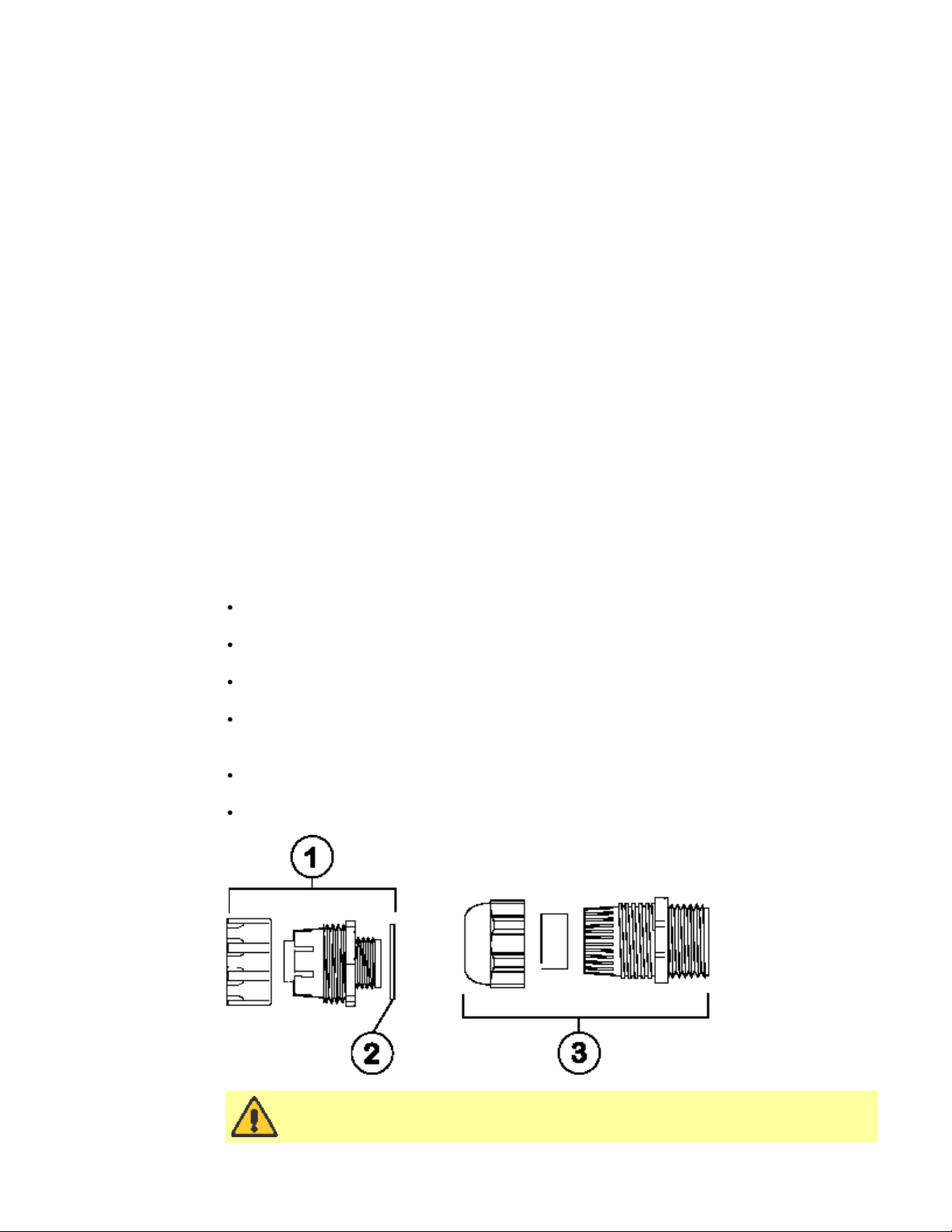
Route the mains supply cable through the entry point to the right of the recess, and
couple the cable to the terminal block. Check rear panel for this information.
The 704S and 704U accept three-core 1.0 square millimetre PVC-sheathed mains cable
(via the screwed adapter supplied) so that a flying lead can be used. The 704S and
704U both accept 20mm rigid or flexible conduit.
Ensure that the mains lead is securely retained in the strain relief gland so that IP55
ingress protection is maintained.
Securely replace the transparent plate and the gasket over the recess.
1. Conduit adaptor
gland GR0018
2. Washer GR0019
3. Cable strain
relief gland
GR0031
Ingress protection standard will be compromised if the transparent plate
is not replaced.
http://www.watson-marlow.it/pdfs-global/m-704su-gb-03.htm[10/07/2012 14:21:14]
Page 4

Watson-Marlow Bredel E-Manuals
8 Troubleshooting
Should the pump fail to operate, make the following checks to determine whether or not
servicing is required.
Check that the power switch is on.
Check the mains supply is available at the pump.
Check the voltage selector switch is in the correct position.
Check the fuse in the mains socket.
Check that the pump is not stalled by incorrect fitting of tubing.
9 704S and 704U Manual operation
Switch on mains power by turning the rotary switch on top of the drive to "I".
Change the set speed by pressing the or key. The 704S and 704U speed control
ratio is better than 50:1. This will give a minimum rotor speed of 7rpm on the 360rpm
drive.
Change direction by pressing the CW/CCW key.
Select the maximum speed: press the key and the Max key together.
Select the minimum speed: press the key and the Max key together.
The keypad has a locking facility to avoid resetting or tampering. If the pump is
stopped, press Stop until the padlock symbol illuminates. If the pump is running, press
Start until the padlock symbol illuminates. All keys will be disabled except for Start and
Stop. Press either of these keys until the padlock symbol extinguishes to unlock the
keypad.
The pump can be set to automatically restart in its operating state set prior to power
interruption, or set so that after power is reconnected the pump will remain stopped. To
invoke the auto-restart facility switch off power to the pump at the mains supply. Press
the Start key while the mains supply is switched back on until the ! symbol illuminates.
Now press Start to start the pump. This facility can be cancelled by turning the mains
supply off and then pressing the Stop key while turning the mains supply back on. The
! symbol will not be illuminated.
Press Start to start the pump. Press Stop to stop the pump.
10 704U Automatic operation
Ensure the Man/Aut keypad switch on the front panel is switched to the auto position so
that the Aut symbol illuminates.
The pump will accept external control signals through the 25 pin cage clamp connector on
the back panel. The auto control cable glands mounting thread size is PG7, accepting 3.0-
5.0mm cable. Remove the cover plate ensuring that the gasket is not damaged.
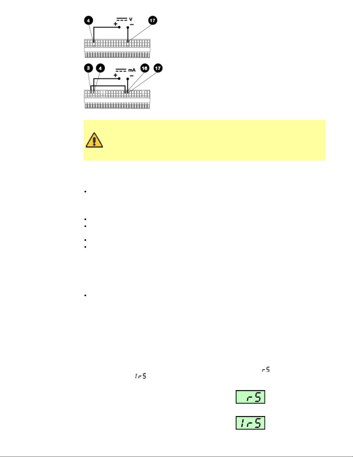
The pump is controllable by an analogue process signal of up to 30V or 32mA. The pump
will provide an increasing flow rate for rising control signal (non-inverted response) or an
increasing flow rate for falling control signal (inverted response).
Signal offset is the process signal level which has to be reached in order for the pump
rotor to start rotating.
Signal range is the change in process signal level necessary to produce the required
change in pump rotor speed.
For example, when using a 4mA to 20mA process signal:
Pump response Signal offset Signal range
Non-inverted 4mA 16mA
Inverted 20mA 16mA
For voltage modes a stable, variable DC voltage source can
http://www.watson-marlow.it/pdfs-global/m-704su-gb-03.htm[10/07/2012 14:21:14]
Page 5
Watson-Marlow Bredel E-Manuals
be used in conjunction with a DC voltmeter, (max 30V DC).
(Refer to the 25 pin terminal strip wiring detail as an
example of control circuitry.) Circuit impedance 100kOhms.
Polarity set for non-inverted response. Reverse polarity for
inverted response.
For current modes the same DC source can be used in
conjunction with a DC milliampere meter, (maximum
32mA). (See 25 pin terminal strip detail.) Circuit
impedance 250Ohms. Polarity set for non-inverted
response. Reverse polarity for inverted response.
Never apply mains voltage across any pins on the 25-pin cage clamp
connector. Up to 30V may be applied across pins 4 and 17, and 5V TTL
on pins 7 and 5, but no voltage should be applied across other pins.
Permanent damage not covered by warranty may result. Do not use the
mains power switch to control the 704U pump for a high repetition of
stop/starts. The auto-control facility should be used.
11 704U Calibration procedure
Turn the signal offset potentiometer (20 turn potentiometer) clockwise until the slider
traverse limit is reached and is signified by a clicking noise. Now turn the potentiometer
10 turns counter-clockwise. Repeat for the signal range potentiometer. This ensures
correct potentiometer set-up for calibration.
Set the process signal offset.
Turn the signal offset potentiometer clockwise to set the pump shaft speed to the
desired minimum.
Set the process signal at its upper range limit (not exceeding 30V or 32mA).
Turn the signal range potentiometer (marked "Range" on back panel) clockwise to set
the drive shaft speed to the desired maximum.
If the process signal or pump speed are set above their designated maximums the pump
will be overloaded which is signified by the signal overload indicator illuminating. The Aut
symbol will flash on the keypad. This is an indication of the limiting control and speed
levels of the drive. Reset to operate within these levels.
Repeat the procedure until pump response coincides exactly with the process signal.
12 Remote auto-manual switch and TTL option
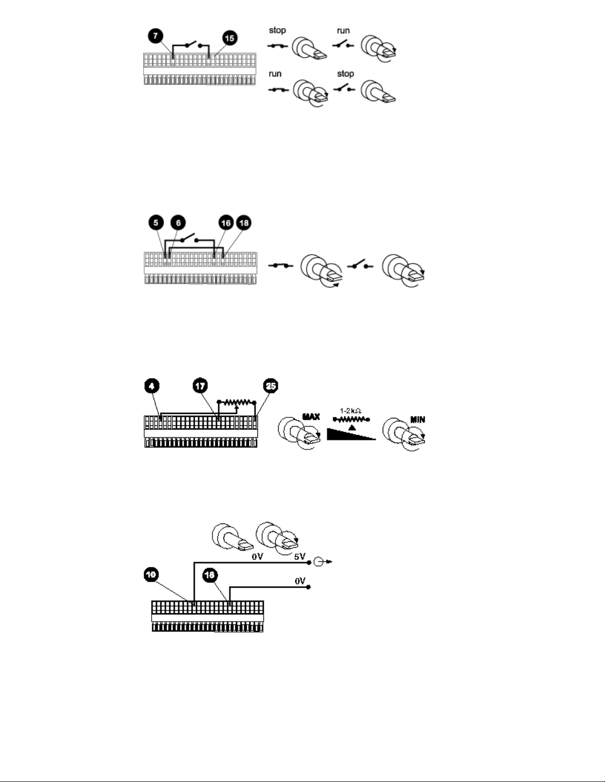
Stop/Start
Connect remote switch between pins 7 and 15 of the 25-pin cage clamp connector.
Alternatively a TTL compatible logic input (Low 0V, High 5V) may be applied to pin 7. Low
input stops the pump, high input runs the pump. With no connection, the pump will default
to running. To invoke either remote stop or inverted remote stop, when switching power to
the pump using the pump on/off switch, press Stop and CW/CCW keys simultaneously.
The pump will indicate its current mode of switching for 2 seconds.
remoted switching, indicates inverted remote switching.
indicates standard
http://www.watson-marlow.it/pdfs-global/m-704su-gb-03.htm[10/07/2012 14:21:14]
Page 6
Watson-Marlow Bredel E-Manuals
Direction
Connect remote switch between pins 5 and 16 and disable the front panel reversing control
by linking pins 6 and 18 of the 25-pin cage clamp connector. Open switch for clockwise
rotation, close for counter-clockwise. Alternatively a TTL compatible logic input (Low 0V,
High 5V) may be applied to pin 5. Low input will run the pump in a counter-clockwise
direction, high input in a clockwise rotation. No connection: the pump will default to
clockwise rotation.
Speed
A remote potentiometer with a nominal value of between 1kW and 2kW with a minimum
power of 0.25W should be wired as shown. When using a remote potentiometer, do not
apply a voltage/current control input signal at the same time. The speed control signal will
require calibration relative to the minimum and maximum settings of the potentiometer.
Use the offset and range potentiometers as described under Calibration, above.
Strobe
The start / stop state of the pump may be monitored by utilising a 5V Hi Lo strobe line
available at the 25-pin cage clamp connector on the pump rear panel. The strobe line will
change state as soon as the motor starts or stops.
Tachometer
This facility can be used to indicate motor speed or total the number of motor revolutions.
When using the square wave, the output is: 360rpm = 4603Hz.
http://www.watson-marlow.it/pdfs-global/m-704su-gb-03.htm[10/07/2012 14:21:14]
Page 7

Watson-Marlow Bredel E-Manuals
13 Guard safety warnings
If the track is lifted while running in each
operating mode the pump will stop and this
warning will be displayed:
When the track has been correctly re-positioned on the pumphead, press any key on the
keypad, then press Start on the keypad and the pump will continue to operate.
14 Error messages
Tachometer fault
Over temperature error
EEPROM error
EEPROM read error
EEPROM write error
EEPROM exhausted error. There is a maximum number
of times the EEPROM can be written to. If is
displayed, the EEPROM must be replaced.
RAM corruption error
15 Care and maintenance
The only scheduled maintenance required for the 704S/R and the 704U/R is inspection of
the motor brushes and their replacement before their length is less than 10mm. The life of
the brushes will depend on the duty of the pump, but is expected to be a minimum of
2,000 hours at maximum speed.
If the pump requires cleaning, use a mild solution of detergent in water after removing the
pumphead. Do not use strong solvents. The sun gear of the gearbox in the 701R, 701RE,
701RX and 701REX pumpheads should be lightly greased with a quality gear grease every
one thousand hours and after cleaning. If harmful liquids are spilled on to the pump, the
case and pumphead should be thoroughly cleaned with detergent and water. Strong
solvents should not be used. The sun gear of the gearbox in the pumphead should be
lightly greased with a good gear grease after the pumphead has been cleaned.
16 Specification
Maximum rotor speed 360rpm
Voltage/frequency 100-120/220-240V 50/60Hz
Control range 50:1
Power consumption 704S, 704U 515VA
Fuse rating Type T (anti-surge) 8A
Operating temperature range 5°C to 40°C
Storage temperature range -40°C to 70°C
http://www.watson-marlow.it/pdfs-global/m-704su-gb-03.htm[10/07/2012 14:21:14]
Page 8

Watson-Marlow Bredel E-Manuals
Weight 31kg
Noise 85dBA at 1m
Standards EN60529 (IP55)
EMC Directive: 89/336/EEC EN50081-1/EN50082-1
Specific drive performance details such as loaded drive speed variation against mains
supply voltage fluctuation and drive stability from a cold start to normal operating
temperature are available on request. For further information please contact WatsonMarlow Technical Support.
Machinery Directive: 98/37/EC EN60204-1
Low Voltage Directive: 73/23/EEC EN61010-1
17 701R, 701RX, 701RG, 701RE, 701REX
Pumphead installation
A correctly engineered installation will promote the best possible tube life, so please ensure
that the following guidelines are followed:
On variable speed models please note that the mechanical speed variator must not be
adjusted when the motor is not running.
Do site the fluid reservoir above the pump wherever possible.
Do keep delivery and suction lines as short and direct as possible.
Do use gradual sweeping bends in installation pipe work with minimum radius equal to five
times the tubing diameter. Avoid tight pipeline bends, pipe reducers and excessive lengths
of smaller bore tubing than that in the pumphead, particularly in pipelines on the suction
side.
Do ensure that there is always a minimum of one metre of smooth bore flexible tubing
connected to the discharge port of the pumphead. This will help minimise any impulse
losses and pulsation in the pipeline. This is especially important with viscous fluids and
rigid pipework.
Do use suction and delivery pipelines with a bore equal to or larger than the bore of the
tube fitted in the pumphead. When pumping viscous fluids, the losses caused by increased
friction can be overcome by using pipe runs with a cross sectional area several times
greater than the pumping element.
Do fit an over-length pump tube in the system to allow its position to be varied relative to
the rotor. This will extend tube life and minimise the downtime of the pumping circuit.
Do ensure that connecting pipe work and fittings are suitably rated to handle the predicted
pipeline pressure.
If rigid pipe work comes in close proximity to the pumphead, a drop out section of pipe
work will simplify tube replacement.
Do keep the pumphead rollers and track clean.
If unsure of an installation please contact your local Watson-Marlow Technical Support
Office for further assistance.
All performance figures in this operating instruction relate to peak pipeline pressures. Peak
pressure is not always accurately shown by oil-filled analogue pressure gauges as damping
of the gauge needle occurs. The pressure being recorded using an analogue gauge may
only be 75% of true peak pressure. For accurate peak pressure measurement a digital
pressure transducer should be used.
18 Tube loading
T704U and 704S pumps can be operated with a 701R continuous tubing pumphead or with
a 701RE pumphead fitted with Watson-Marlow LoadSure tube elements. For both
pumphead types, extension "X" pumphead options are available.
http://www.watson-marlow.it/pdfs-global/m-704su-gb-03.htm[10/07/2012 14:21:14]
Page 9

Watson-Marlow Bredel E-Manuals
701R, 701RX and 701RG continuous tube loading
Loosen the track compression spring knobs using a 10mm A/F spanner, turning them
anticlockwise six (6) times.
Unscrew the track securing bolt and withdraw the bolt fully. Lift the track by its handle
and slide out from under the springs.
Release the tube clamps by pulling on the release levers and lift out both clamps.
Lay the tubing across the pumphead. Secure the suction side by sliding in the first tube
clamp while pulling the release lever.
Fit the delivery clamp loosely to allow any excess tubing to work its way through the
pumphead. (See Re-tensioning the tubing, below).
Slip the right hand end of the track under the springs and position the left hand end so
the track securing bolt can be inserted.
Tighten the track securing bolt with the 6mm Allen key provided.
Tighten both the track compression spring knobs to a torque of 3Nm (2.2 lb-ft) using a
10mm A/F spanner.
Note: If two pumpheads are fitted each with 25.4mm bore tubing, the maximum allowable
output pressure is 1bar (14.5 psig) per channel.
Re-tensioning the tubing
Start the pump with the guard in place, allowing any
excess tubing to work through the pumphead, then press
down the delivery end clamp firmly. Check the tube for
movement when the pump is running. If tubing moves
through the pumphead, the tube should be more firmly
clamped at the suction end. The delivery end should be
unclamped to release any excess tubing, pulled tight and
then firmly re-clamped again. Repeat as necessary.
When using Marprene continuous tubing, after the first 30
minutes of running, re-tension the tube in the pumphead by releasing the tube clamp on
the delivery side a little and pulling the tube tight. This is necessary to counteract the
normal stretching that occurs with Marprene which can go unnoticed and result in poor
http://www.watson-marlow.it/pdfs-global/m-704su-gb-03.htm[10/07/2012 14:21:14]
Page 10

Watson-Marlow Bredel E-Manuals
tube life.
701RE and 701REX LoadSure tube element loading
700 series LoadSure tube elements:
remove the chance of premature tube failure caused by incorrect tube loading;
avoid over-clamping of tubing;
remove the need to re-tension the tubing;
extend tube life;
reduce maintenance time for tube changeover and cleaning;
offer standard industrial tube connections.
Loosen the track-compression spring knobs using a 10mm A/F spanner, turning them
anticlockwise six (6) times.
Unscrew the track-securing bolt and withdraw the bolt fully. Lift the track by its handle
and slide it out from under the springs.
Locate the D-shaped flange fitted to the end of the tube element into the delivery (righthand) sliding tube clamp. (The D flange ensures that the element can only be loaded
correctly.)
Slip the right-hand end of the track under the springs.
Locate the second D-shaped flange into the suction (left-hand) sliding tube clamp.
(Lifting the sliding tube clamp will aid the tube-loading.)
Position the left-hand end of the track so that the track-securing bolt can be inserted.
Tighten the track-securing bolt with the 6mm Allen key provided.
Tighten both the track-compression spring knobs to a torque of 3Nm (2.2 lb-ft) using a
10mm A/F spanner.
Connect both ends of the element to the rest of the system using industrial-standard
cam and groove connectors.
19 Fitting an extension pumphead
The procedure for fitting an extension pumphead is the same for 701R and 701RE first
pumpheads. The 701R procedure is pictured below.
http://www.watson-marlow.it/pdfs-global/m-704su-gb-03.htm[10/07/2012 14:21:14]
Page 11

Watson-Marlow Bredel E-Manuals
From the first pumphead remove:
the plug from the tapped hole in the top right hand corner;
the track securing bolt and the track;
the plug from the slot in the centre shaft;
the M8 x 16 socket head cap screw from the bottom left of the first pumphead.
Grease the drive shaft dog of the extension pumphead with the grease supplied.
Apply thread locking compound to the M8 x 16 socket head cap screw in the top right
hand corner of the backplate of the extension pumphead.
Align the drive shaft dog of the extension pumphead with the slot in the drive shaft of
the first pumphead.
Fit the extension pumphead to the first pumphead.
Ensure the backplate of the extension pumphead is flat
against the frontplate of the first pumphead.
Lightly tighten the socket head cap screw with the
modified 6mm Allen key provided.
Apply thread locking compound to the M8 x 170 socket
head cap screw in the bottom left of the extension
pumphead frontplate, and tighten it in sequence with
the M8 cap screw in the backplate.
20 Pumphead spares: continuous tubing
Models 701RB, 701RBX, 701RBG
1 MRA0027A Pivot pin assembly
1 MRA0034A Pivot pin assembly
2 MRA0021A Rotor assembly
2 MRA0036A Rotor assembly ~
3 701RB, 701RBX:
MRA0104A
701RBG:
MRA0295A
3 MRA0103A Knob assembly ~
4 701RB, 701RBX:
SG0005
701RBG: SG0019
4.8mm wall tubing
3.2mm wall tubing
~701RX
701RX
Knob assembly ~
Spring
http://www.watson-marlow.it/pdfs-global/m-704su-gb-03.htm[10/07/2012 14:21:14]
5 701RB, 701RBX:
MR0674T
701RBG:
MR0977T
501RL Spring retaining
washer
Page 12

Watson-Marlow Bredel E-Manuals
6 MR0880C Tube clamp
7 MR0662T Stud ~ Set to 61mm
8 MRA0154A Track assembly
9 MR0882M Eccentric bush
21 Pumphead spares: tubing elements
Models 701RBE, 701RBEX
1 MRA0027A Pivot pin assembly
1 MRA0034A Pivot pin assembly ~701RX
2 MRA0021A Rotor assembly
2 MRA0036A Rotor assembly ~ 701RX
3 MRA0104A Knob assembly ~ 4.8mm wall
tubing
3 MRA0103A Knob assembly ~ 3.2mm wall
4 SG0005 Spring
5 MR0674T Spring retaining washer
6 MR0662T Stud ~ Set to 61mm
7 MR1118T Sliding clamp
8 MRA0154A Track assembly
9 MR0882M Eccentric bush
22 Pumphead spares: rotor
All models
tubing
1 MR0667T Spacer
2 FN0420 Screw M5x16 socket
countersunk
3 FN0722 Washer
4 MRA0020A Roller assembly
5 MRA0039A Shaft with sun gear
~701R
http://www.watson-marlow.it/pdfs-global/m-704su-gb-03.htm[10/07/2012 14:21:14]
5 MRA0040A Shaft with sun gear
~701RX
6 MR0879C Rotor flange
7 BB0018 Bearing
Page 13

Watson-Marlow Bredel E-Manuals
23 Drive spares
All models
1 SW0086 Voltage selector
switch
2 FS0061 Mains fuse T type
8.0A
3 MR0669S Terminal inspection
window
4 MR0771S Terminal window
gasket
5 MRA0214A Transformer
6 MRA0222A Control PCB
assembly Mk2
7 MRA0201A Analogue PCB
assembly ~704U
8 MN1086S Remote connection
inspection cover
~704U
All models
9 MN1087S Remote connection
inspection cover
gasket ~704U
10 MO0093 Motor
11 MR0690S Vertical gasket: 4
per pump
12 MR0691S Horizontal gasket:
2 per pump
13 MRA0203A Tacho PCB
assembly
14 MR1081H Tacho sensor
15 OS0020 Drive belt
16 BM0008 Bush and holder: 2
per pump
17 MR1084H Magnetic guard
switch
18 FS0043 Control PCB fuse
5.0A T Type
ceramic 20mm
http://www.watson-marlow.it/pdfs-global/m-704su-gb-03.htm[10/07/2012 14:21:14]
21 SW0129 Switch contact
block: 2 per pump
22 SW0127 Switch mechanism
23 MRA0224A IC ROM 704S/U
24 MR1064B Keypad ~704S
24 MR1053B Keypad ~704U
25 MRA0205A CPU/display PCB
assembly
26 MR0690S Vertical gasket: 4
per pump
Page 14

Watson-Marlow Bredel E-Manuals
mm inch # STA-PURE
24 Flow rates
Flow rates were obtained using silicone tubing with the pumphead rotating clockwise,
pumping water at 20°C with zero suction and delivery pressures. For critical applications
determine flow rates under operating conditions.
Tube bore Tube number - # rpm Pressure (+) Suction (-)
Flow rates: 701R Flow rates: 701RE
mm 9.6 12.7 15.9 19.0 25.4 12.7 15.9 19.0
inch 3/8 1/2 5/8 3/4 1 1/2 5/8 3/4
# 193 88 189 191 92 88 189 191
360 420 780 1080 1500 2000 780 1080 1500
25 701R product codes
mm inch # Marprene
9.6 3/8 193 902.0096.048 903.0096.048 913.A096.048
12.7 1/2 88 902.0127.048 902.0127.PPC 903.0127.048 913.A127.048
15.9 5/8 189 902.0159.048 902.0159.PPC 903.0159.048 913.A159.048
19.0 3/4 191 902.0190.048 902.0190.PPC 903.0190.048 913.A190.048
25.4 1 92 902.0254.048 903.0254.048 913.A254.048
mm inch # Neoprene
Marprene
LoadSure
Neoprene
LoadSure
Bioprene
Butyl Fluorel
Platinum
silicone
9.6 3/8 193 920.0096.048
12.7 1/2 88 920.0127.048 920.0127.PPC
15.9 5/8 189 920.0159.048 920.0159.PPC
19.0 3/4 191 920.0190.048 920.0190.PPC 930.0190.048 970.A190.048
25.4 1 92 920.0254.048 930.0254.048
http://www.watson-marlow.it/pdfs-global/m-704su-gb-03.htm[10/07/2012 14:21:14]
Page 15

Watson-Marlow Bredel E-Manuals
9.6 3/8 193 960.0096.048
12.7 1/2 88 960.0127.048
15.9 5/8 189 960.0159.048
19.0 3/4 191 960.0190.048
25.4 1 92 960.0254.048
26 Flow, pressure and suction
27 Maximum peak working pressure ratings
701RB 701RBX 701RBG 701RBE 701RBEX
2bar 2bar 2bar 2bar 2bar
28 Outline dimensions
Measurements are given in millimetres.
29 Trademarks and disclaimer
http://www.watson-marlow.it/pdfs-global/m-704su-gb-03.htm[10/07/2012 14:21:14]
Page 16

Watson-Marlow Bredel E-Manuals
Watson-Marlow, Bioprene, LoadSure and Marprene are trademarks of Watson-Marlow
Limited.
Fluorel is a trademark of 3M.
Sta-Pure is a trademark of W.L.Gore & Associates.
Disclaimer The information contained in this document is believed to be correct but
Watson-Marlow Limited accepts no liability for any errors it contains, and reserves the right
to alter specifications without notice.
30 Warning not to use pumps in patientconnected applications
Warning These products are not designed for use in, and should not be used for patient
connected applications.
31 Publication history
Watson-Marlow 704U, 704S
14 06 02: First published in html. m-704su-gb-02.htm. PB0275GB02
19 06 02: Dimension update. m-704su-gb-03.htm. PB0275GB03
32 Decontamination certificate
In compliance with the UK Health and Safety at Work Act and the Control of Substances
Hazardous to Health Regulations, you are required to declare the substances which have
been in contact with product(s) you return to Watson-Marlow or its subsidiaries or
distributors. Failure to do so will cause delays. Please ensure that you fax us this form and
receive an RGA (Returned Goods Authorisation) before you despatch the product(s). A
copy of this form must be attached to the outside of the packaging containing the
product(s). Please complete a separate decontamination certificate for each product.
Your name Company
Address
Postcode/zip Country
Telephone Fax
Product type Serial number
To speed the repair, please
describe all known faults
The product has ...
Names of chemicals
handled with product(s)
You are responsible for cleaning and decontaminating the product(s) before return.
Been used Not been used
If the product has been used, please complete all the following sections. If the product has
not been used, please just sign this form.
Precautions to be taken in
handling these chemicals
http://www.watson-marlow.it/pdfs-global/m-704su-gb-03.htm[10/07/2012 14:21:14]
Page 17

Watson-Marlow Bredel E-Manuals
Action to be taken in the
event of human contact
I understand that the personal data collected will be kept confidentially in accordance with
the UK Data Protection Act 1998.
RGA number
Signature
Your position
Date
Please print out, sign and fax to Watson-Marlow Pumps at +44 1326 376009.
http://www.watson-marlow.it/pdfs-global/m-704su-gb-03.htm[10/07/2012 14:21:14]
 Loading...