

Page 1

701S/R
Drive/s: Issue 4
EPROM: N/A
Pumphead/s: Issue1
Watson-Marlow manual control high flow pump
Installation and operating instructions
Publication PB 0142
Issue 2
Page 2
Contents
Declarations .................................................... Page 2
Two-year warranty .................................................... Page 3
Safety .................................................... Page 3
Information for returning pumps .................................................... Page 3
Recommended operating procedures ............................................. Page 4
Part 1: 701S/R Drive
Siting .................................................... Page 5
Installation .................................................... Page 5
Part 2: Operation
Overview .................................................... Page 6
Part 3: Maintenance
Fitting a second pumphead .................................................... Page 7
Tube loading .................................................... Page 8
Part 4: Appendices
Flow rates .................................................. Page 10
Declaration of
conformity
Tubing range .................................................. Page 10
Specification .................................................. Page 11
Care and maintenance .................................................. Page 11
Pumphead spares .................................................. Page 12
Drive spares .................................................. Page 14
Outline drawing .................................................. Page 15
Decontamination certificate .................................................. Page 16
Declarations
When the 701S/R pump unit is used as stand alone pump it complies with:
Machinery Directive 89/392EEC and EN60204-1
Low Voltage Directive 73/23/EEC and EN61010-1
EMC Directive 89/336/EEC and EN50081-1/EN50082-1
Responsible person: Dr R Woods, Managing Director, Watson-Marlow
Limited, Falmouth, Cornwall TR11 4RU, England.
Telephone 01326 370370 Fax 01326 376009
Declaration of
incorporation
When the 701S/R pump is to be installed into a machine or is to be
assembled with other machines for installations, it must not be put into
service until the relevant machinery has been declared in conformity with the
provisions of the Machinery Directive 89/392/EEC and EN60204-1.
Responsible person: Dr R Woods, Managing Director, Watson-Marlow
Limited, Falmouth, Cornwall TR11 4RU, England.
Telephone 01326 370370 Fax 01326 376009
Page 2
Page 3
Two-year warranty
Watson-Marlow Limited warrants, subject to the conditions below, through
either Watson-Marlow Limited, its subsidiaries, or its authorised distributors,
to repair or replace free of charge, including labour, any part of this product
which fails within two years of delivery of the product to the end user. Such
failure must have occurred because of defect in material or workmanship and
not as a result of operation of the product other than in accordance with the
instructions given in this manual.
Conditions of and specific exceptions to the above warranty are:
· Consumable items such as tubing and glands are excluded.
· Products must be returned by pre-arrangement carriage paid to Watson-
Marlow Limited, its subsidiaries, or its authorised distributor.
· All repairs or modifications must have been made by Watson-Marlow
Limited, its subsidiaries, or its authorised distributors or with the express
permission of Watson-Marlow Limited, its subsidiaries, or its authorised
distributors.
· Products which have been abused, misused, or subjected to malicious or
accidental damage or electrical surge are excluded.
Warranties purporting to be on behalf of Watson-Marlow Limited made by any
person, including representatives of Watson-Marlow Limited, its subsidiaries,
or its distributors, which do not accord with the terms of this warranty shall not
be binding upon Watson-Marlow limited unless expressly approved in writing
by a Director or Manager of Watson-Marlow Limited.
Safety
In the interests of safety, this pump and the tubing selected should only be
used by competent, suitably trained personnel after they have read and
understood this manual, and considered any hazard involved.
Any person who is involved in the installation or maintenance of this
equipment should be fully competent to carry out the work. In the UK this
person should also be familiar with the Health and Safety at Work Act 1974.
Ensure the drive is inoperative before opening the track cover
There are dangerous voltages (at mains potential) inside the unit. If access is
required, isolate the pump from the mains before removing the cover.
Information for returning pumps
In the current situation of heightened concern over the handling of hazardous
materials, any equipment which has been contaminated with, or exposed to,
body fluids, toxic chemicals or any other substance hazardous to health must
be decontaminated before it is returned to Watson-Marlow or its distributor.
A certificate (a suitable blank form is included at the rear of these operating
instructions), or signed statement, must be attached to the outside of the
shipping carton.
This certificate is required even if the pump is unused. If the pump has been
used, the fluids that have been in contact with the pump and the cleaning
procedure must be specified along with a statement that the equipment has
been decontaminated.
Page 3
Page 4

Recommended operating procedures
DO keep delivery and suction lines as short as possible.
DO use the minimum number of bends in rigid pipe runs. If there must be a
bend, use a swept bend and not a tight elbow
DO use suction and delivery pipelines with a bore equal to or larger than the
bore of the tube fitted in the pumphead. When pumping viscous fluids, the
losses caused by increased friction can be overcome by using pipe runs with
a cross sectional area several times greater than the pumping element.
DO use the largest possible bore tube running at slow speed for the longest
tube life.
DO fit an extra length of pump tube in the system so that you can move the
tube through the pumphead occasionally, without needing to break the
pumping circuit. This is particularly useful for extending tube life in long
running sterile applications.
DO keep the track and rollers clean, and ensure that the rollers are free.
DO NOT fit valves in the suction or delivery line without considering that
peristaltic pumps are self priming and will hold their prime up to several
metres, so there may be no need for non-return or foot valves, nor for the
loading valves required on many other kinds of pumps.
Any valves fitted must cause no restriction. If electrically actuated valves are
fitted, they should be interlocked so that the pump will only run when the
valves are open. Fit an automatic by-pass if manual valves are installed.
When using Marprene or Bioprene tubing, after the first 30 minutes of
running, re-tension the tube in the pumphead by releasing the tube clamp on
the delivery side a little and pulling the tube tight. This is to counteract the
normal stretching that occurs with Marprene and Bioprene, which can go
unnoticed and result in poor tube life.
Tube selection The chemical compatibility list published in the WatsonMarlow catalogue is only a guide. If in doubt about the compatibility of a tube
material and the duty fluid, request a tube sample card for immersion trials.
Remember the sample will be fully immersed, but the fluid when in use will
only be in contact with the inside of the tube. If the material swells but does
not lose its strength it may be worth considering.
Viscous dispensing To overcome the common problems of reduced
accuracy and dripping delivery pipes, the suction and delivery lines should be
kept as short as possible. Use larger bore transmission tubing than that in the
pumphead to keep the friction losses to a minimum. Improved accuracy will
be noticed if rigid or semi-rigid pipe is used on the delivery side. The rigid tube
is effective in reducing over-run because it does not expand during pumping.
Page 4
Page 5
Part 1: 701S/R Drive
Siting
The 701S/R can be operated at ambient temperatures from 5C to 40C.
Storage temperatures from -40C to 70C are permissible, but allow time for
acclimatisation before use. The pump should be positioned to allow a free
flow of air around it.
Should the pump fail to operate, check that mains electricity is available at the
unit, that the fuses are intact and that the pump is not stalled by incorrect
fitting of tubing.
A drain hole (tapped 1/4" BSP) is provided at the left hand side of the
pumphead base which is plugged during assembly. If required, the plug can
be removed and a drain hose connected.
Installation
The 701S/R is suitable for single phase mains electricity only. Ensure that the
supply voltage and frequency correspond with those marked with a white dot
on the rear panel, (220V 50/60Hz, 120V 50/60Hz or 100V 50/60Hz).
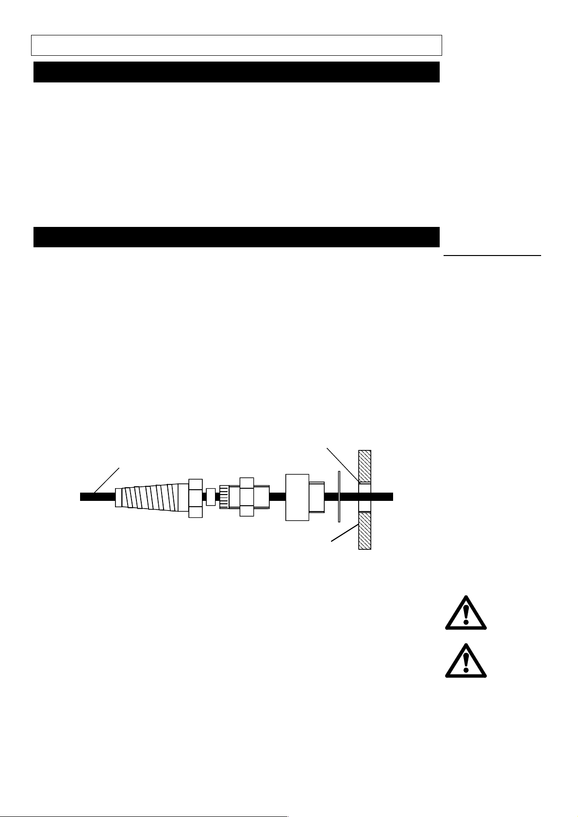
Remove the small plate on the rear panel to gain access to the terminal block.
Route the mains cable through the entry point to the right of the recess and
couple the cable to the terminal block in accordance with the instructions
printed on the rear panel. Two alternative connectors are supplied to screw
into the entry point gland. One accepts 20mm rigid or flexible conduit, and the
other accepts a three core 0.75 square mm PVC sheathed mains cable (via
the screwed adaptor provided) so that a flying lead can be used. Securely
replace the transparent plate and gasket over the recess.
Power cable
5 to 8mm outside diameter
M20 for direct conduit connection
Supplies
Back panel
Ingress protection standard will be compromised if transparent plate is
not properly replaced.
There are dangerous voltages (at mains potential) inside the motor. If
access is required, isolate the pump from the mains before removing
the cover.
Page 5
Page 6

Part 2: Operation
Overview
Select the direction of rotation with the forward/off/reverse switch on the left
hand side of the control panel and start the pump using the green start
button. The preferred direction of rotation is clockwise (giving a flow direction
of left to right when facing the pump), which will ensure the longest tube life.
To stop the pump, turn the forward/off/reverse switch to its central off
position. To change direction of flow, turn the forward/off/reverse switch
through its central off position to the other direction and restart the pump with
the green start button.
If at any time the pump fails to start, it is likely that the inbuilt protection
circuitry is operating. Turn the forward/off/reverse switch to its central off
position (you should hear the contactor drop out), and then to the required
direction of rotation again. Wait 10 seconds and press the green start button.
The speed control range of the 701S/R is from 2% to 100% of the rated
maximum speed (360rpm at the rotor). The speed setting dial has a locking
knob to prevent accidental speed changes.
If the pump is to be used at low speed settings under manual control, and
there is a risk that damage could be caused to the process if the pump is
taken to higher speeds, then the speed limiting potentiometer in the rear
panel recess can be brought into use. First, remove the panel covering the
rear panel recess and turn the speed limiting potentiometer fully anticlockwise. Next, turn the front panel speed potentiometer fully clockwise.
Start the pump (which will run very slowly - if at all) and turn the rear panel
speed limiting potentiometer clockwise until the pump reaches the desired
maximum speed. Securely replace the panel with an intact gasket over the
rear panel recess. It will now be found that the pump speed can be varied
over a limited range from the front panel potentiometer.
Note that as the maximum speed is reduced using the speed limiting
potentiometer, the speed control ratio is also reduced. The minimum speed at
which the 701S/R will run is about 7rpm. If the speed limiting potentiometer is
set to reduce the maximum speed to, say, 35rpm, then the speed control ratio
will be 7rpm to 35rpm, which is a speed control ratio of 5:1.
Page 6
Page 7

Part 3: Maintenance
Fitting a second pumphead
701S/R pump may be fitted with one 701RX extension pumphead to give two
channels of flow. There is no restriction on the size of tube which can be used
in each pumphead when two pumpheads are fitted, but if two tubes of
25.4mm bore are fitted, the maximum output pressure against which the
pump can operate is 1.5 bar (22 psig).
1. Remove the plug from the slot in the centre shaft of the first pumphead,
and remove the plug from the tapped hole on the top right hand corner of
the first pumphead.
2. Remove the track securing bolt and the track from the first pumphead.
Remove the M8 x 16 socket head cap screw from the bottom left (just
above the left hand foot) of the first pumphead.
3. Remove the track securing bolt and the track from the extension
pumphead.
Grease the drive shaft tongue of the extension pumphead with the grease
supplied. Turn the centre shaft of the extension pumphead until its drive shaft
tongue is aligned with the slot in the drive shaft of the first pumphead.
Apply thread locking compound to the M8 x 16 socket head cap screw in the
top right hand corner of the backplate of the extension pumphead. Fit the
701RX extension pumphead to the first pumphead, ensuring that the
backplate of the extension pumphead is flat against the frontplate of the first
pumphead.
Tubing
considerations
Important
4. Tighten the socket head cap screw in the top right hand corner of the
extension pumphead with the modified Allen key supplied.
5. Apply thread locking compound to the M8 x 170 socket head cap screw in
the bottom left of the extension pumphead frontplate, and tighten it with
the Allen key supplied.
Follow the tube loading instructions in the next section for each pumphead,
using the double length bolt to secure both tracks.
6. Tighten the track securing bolt with the Allen key provided to prevent
removal by hand.
Page 7
Page 8

Tube loading
1. If the pump is running, stop it by turning the forward/off/reverse switch to
its central position. The track acts as a guard to the rotor, and should not
be removed until the pump has been stopped.
2. Turn the track compression spring knobs anti-clockwise about six turns.
This raises the springs and aids both track removal and replacement.
3. Release the track by unscrewing the track securing bolt on the left hand
side of the pumphead and withdrawing the bolt fully. Lift the track by its
handle and slide out the right hand side of the track from under the
springs.
4. Release in turn the two tube clamps by pulling on the release levers on
either side of the front plate of the pumphead, and lift out both clamps.
5. Lay the tubing across the pumphead and secure the suction side by
sliding in the first tube clamp (with its lip pointing outwards) and pressing it
down firmly. Loosely fit the second tube clamp.
6. Slip the right hand end of the track under the springs and position the left
hand end so that the track securing bolt can be inserted.
7. Tighten the track securing bolt with the Allen key provided to prevent
removal by hand. The Allen key size is 6mm. Spare Allen keys are
available from Watson-Marlow Limited or its distributors.
When the track has been fitted, screw down both the spring adjuster nuts
fully.
Page 8
Page 9

Start the pump, allow any excess tubing to work through the pumphead, and
press the delivery end clamp down firmly. Check the tube for movement when
the pump is running.
If there is any sign of the tube working its way through the pumphead, the
tube should be more firmly clamped at its suction end, the delivery end
unclamped to release any excess tubing, pulled tight and then firmly
reclamped again.
When using Marprene tubing, it is advised that the above procedure is
carried out after approximately 30 minutes running time following initial
tube loading. If the direction of flow is reversed, the tube should again
be checked for movement.
Retensioning
the tubing
Page 9
Page 10

Part 4: Appendices
Flow rates
These flow rates were obtained using Marprene tubing pumping water at 20C
with zero suction and delivery pressures (unless otherwise stated). Where an
application is critical, the flow rate should be determined under operating
conditions. The important factors are suction and delivery pressures,
temperature, fluid viscosity and tube material.
Flow rates 701S/R (litres/hr) Minimum flows 2% of rates given
Tube # 193 88 189 191 92
Tube bore 9.6mm 12.7mm15.9mm 19.0mm25.4m
m
3/8" 1/2" 5/8" 3/4" 1"
360rpm 420 780 1080 1500 2000
Tubing range
Pump performance depends upon the accuracy and consistency of the
tubing. Watson-Marlow tubing is specially formulated for peristaltic pumping
and it is manufactured and quality controlled to our own specifications. We
recommend Marprene tubing whenever it is chemically suitable.
701S/R Tubing range product codes
Bore Tube # Marprene Silicone
9.6 mm 3/8" 193 902.0096.048 910.0096.048
12.7mm 1/2” 88 902.0127.048 910.0127.048
15.9mm 5/8” 189 902.0159.048 910.0159.048
19.0mm 3/4” 191 902.0190.048 910.0190.048
25.4mm 1” 92 902.0254.048 910.0254.048
Bore Tube # Neoprene Bioprene
9.6mm 3/8" 193 920.0096.048 903.0096.048
12.7mm 1/2” 88 920.0127.048 903.0127.048
15.9mm 5/8” 189 920.0159.048 903.0159,048
19.0mm 3/4” 191 920.0190.048 903.0190.048
25.4mm 1” 92 920.0254.048 903.0254.048
Bore Tube # Butyl* Viton
19.0mm 3/4” 191 930.0190.048 970.0190.048
25.4mm 1” 92 930.0254.048
* Butyl tubing should not be used at pumphead speeds greater than 200rpm.
Page 10
Page 11

Specification
Nominal maximum rotor speed 360rpm
Speed control ratio 50:1
Maximum power consumption 750VA
Operating temperature range 5C to 40C
Storage temperature range -40C to 70C
Weight 26kg
Noise ( one pumphead ) <78dBA at 1m
Standards IEC 335-1, EN60529 (IP55)
Machinery Directive: 89/392EEC
and EN602041
Low Voltage Directive: 73/23/EEC
and EN61010-1
EMC Directive: 89/336/EEC
and EN50081-1/EN50082-1
Care and maintenance
The 701S/R uses a permanent magnet direct current motor with a pulsewidth-modulated speed controller which provides black commutation. The
only scheduled maintenance required for the 701S/R is inspection of the
motor brushes and their replacement before their length is less than 10mm.
The life of the brushes will depend on the duty of the pump, but is expected to
be at least 2000 hours at maximum speed.
The sun gear of the gearbox in the 701R and 701RX pumpheads should be
lightly greased with a quality gear grease every one thousand hours. If
harmful liquids are spilled on to the pump, the case and pumphead should be
thoroughly cleaned with detergent and water. Strong solvents should not be
used. The sun gear of the gearbox in the pumphead should be lightly greased
with a quality gear grease after the pumphead has been cleaned.
Page 11
Page 12

Pumphead spares
Page 12
Page 13

Page 13
Page 14

Drive spares
Page 14
Page 15

Outline drawing
Page 15
Page 16

Decontamination certificate
.
g
g
g
Watson-Marlow Limited Health and Safety Declaration
1.0
This procedure is a legal requirement in the UK
and
be used when returning pumps and to Watson-Marlow (or its distributor) to
must
equipment for service at Watson-Marlow (or its that we have the information
3.0
Either fax this form or send by first class post
receipt of the
before
ensure
distributor). equipment.
2.0
Pumps returned for service must be cleaned.
You are responsible for their decontamination. outside
A further copy must be attached to the
of the shipping case.
Failure to complete the form or comply with the procedure will cause delays in servicing the equipment.
4.0
Company .......................................................................................................................................................
Address .......................................................................................................................................................
......................................................... Post Code........................................................
Telephone ......................................................... Fax number.....................................................
5.0
Please complete
the following sections
all
5.4
If substances are not hazardous nor toxic,
please complete section 5.4.1.
If substances are hazardous or toxic,
5.1
Pump Type....................................................... please complete section 5.4.2.
5.2
Serial number...................................................
5.4.1
I hereby confirm that the equipment specified
has not pumped nor come into contact with
any toxic or hazardous substances.
5.3
Details of substances pumped
Si
ned.............................................................
5.3.1
Chemical names: Name...............................................................
(a) ................................................................... Position...........................................................
(b) ................................................................... Date.................................................................
(c) ...................................................................
(d) ...................................................................
5.4.2
I hereby confirm that the only toxic or
hazardous substance(s) that the equipment
5.3.2
Precautions to be taken in handling these specified has pumped or come into contact
substances: with are those named, and that the
(a) ................................................................... information given is correct and the carrier
(b) ................................................................... has been informed if the consignment is of
(c) ................................................................... a hazardous nature.
(d) ...................................................................
Si
ned.............................................................
5.3.3
Action to be taken in the event of human Name..............................................................
contact: Position...........................................................
(a) ................................................................... Date................................................................
(b) ...................................................................
(c) ...................................................................
5.5
Carrier to be used
(d) ................................................................... ........................................................................
Delivery date
5.3.4
Cleaning fluid to be used if residue of ........................................................................
chemicals is found during servicing:
(a) ...................................................................
5.6
Fault description or any other information
(b) ................................................................... ........................................................................
(c) ................................................................... ........................................................................
(d) ................................................................... ........................................................................
........................................................................
........................................................................
IMPORTANT
Before returning any product for service, this form
be completed and sent to
must
Watson-Marlow, or its subsidiary, or its official distributor undertaking the service
Watson-Marlow Limited, Falmouth, Cornwall TR11 4RU, En
land. Tel 01326 370370, Fax 01326 376009
Page 16
 Loading...