

Page 1

WATSON-MARLOW BREDEL E-MANUALS
p
PB0230GB02
Page 1 of 25Watson-Marlow Bredel E-Manuals
Watson-Marlow 701 baseplate
umps
Contents
1. Declaration of conformity
2. Declaration of incorporation
3. Warranty
4. Information for returning pumps
5. Safety
6. Recommended operating
procedures
7. Installation
8. Troubleshooting
9. AC Motor maintenance
10. Gearbox maintenance
11. 701PB air motors
12. 701PB air motors:
troubleshooting
13. Pump specification
14. 701RB pumphead: key safety
information
15. 701R safe-guarding
16. 701RB, 701RBX, 701RBG, 701RBE, 701RBEX
Pump installation
17. Tube loading
18. Fitting an extension pumphead
19. Pumphead spares: continuous tubing
20. Pumphead spares: tubing elements
21. Pumphead spares: rotor
22. Flow rates
23. 701RB, 701RBX, 701RBG, 701RBE, 701RBEX
product codes
24. Flow, pressure and suction
25. Maximum peak working pressure ratings
26. Outline dimensions
27. Trademarks and disclaimer
28. Warning not to use pumps in patient-connected
applications
29. Decontamination certificate
14/12/2009file://M:\staging\pdfs-global\m-701baseplate-gb-02.htm
Page 2
Page 2 of 25Watson-Marlow Bredel E-Manuals
14/12/2009file://M:\staging\pdfs-global\m-701baseplate-gb-02.htm
Page 3
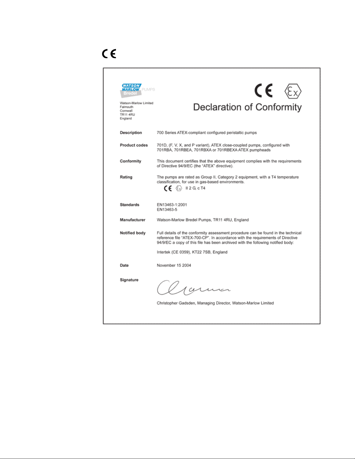
1 Declaration of conformity
When this pump unit is used as a stand alone pump it complies with: Machinery
Directive 2006/42/EC, EMC Directive 2004/108/EC.
Page 3 of 25Watson-Marlow Bredel E-Manuals
14/12/2009file://M:\staging\pdfs-global\m-701baseplate-gb-02.htm
Page 4

Page 4 of 25Watson-Marlow Bredel E-Manuals
2 Declaration of incorporation
When this pump unit is to be installed into a machine or is to be assembled with other
machines for installations, it must not be put into service until the relevant machinery has
been declared in conformity with the Machinery Directive 2006/42/EC.
Responsible person: Christopher Gadsden, Managing Director, Watson-Marlow Limited,
Falmouth, Cornwall TR11 4RU, England. Telephone +44 (0) 1326 370370 Fax +44 (0) 1326
376009.
14/12/2009file://M:\staging\pdfs-global\m-701baseplate-gb-02.htm
Page 5

R
Page 5 of 25Watson-Marlow Bredel E-Manuals
3 One year warranty - 701PB/
Watson-Marlow Limited warrants, subject to the conditions below, through either WatsonMarlow Limited, its subsidiaries, or its authorised distributors, to repair or replace free of
charge, including labour, any part of this product which fails within one year of delivery of
the product to the end user. Such failure must have occurred because of defect in material
or workmanship and not as a result of operation of the product other than in accordance
with the instructions given in this manual.
Two year warranty - 701FB/R, 701DVB/R,
701DFB/R, 701IB/R
Watson-Marlow Limited warrants, subject to the conditions below, through either WatsonMarlow Limited, its subsidiaries, or its authorised distributors, to repair or replace free of
charge, including labour, any part of this product which fails within two years of delivery of
the product to the end user. Such failure must have occurred because of defect in material
or workmanship and not as a result of operation of the product other than in accordance
with the instructions given in this manual.
Conditions of and specific exceptions to the above warranty are
Consumable items such as tubing and rollers are excluded.
Products must be returned by pre-arrangement carriage paid to Watson-Marlow Limited,
its subsidiaries, or its authorised distributor.
All repairs or modifications must have been made by Watson-Marlow Limited, its
subsidiaries, or its authorised distributors or with the express permission of WatsonMarlow Limited, its subsidiaries, or its authorised distributors.
Products which have been abused, misused, or subjected to malicious or accidental
damage or electrical surge are excluded.
Warranties purporting to be on behalf of Watson-Marlow Limited made by any person,
including representatives of Watson-Marlow Limited, its subsidiaries, or its distributors,
which do not accord with the terms of this warranty shall not be binding upon WatsonMarlow Limited unless expressly approved in writing by a Director or Manager of WatsonMarlow Limited.
4 Information for returning pumps
Equipment which has been contaminated with, or exposed to, body fluids, toxic chemicals
or any other substance hazardous to health must be decontaminated before it is returned to
Watson-Marlow or its distributor. A certificate included at the rear of these operating
instructions, or signed statement, must be attached to the outside of the shipping carton.
This certificate is required even if the pump is unused. If the pump has been used, the
fluids that have been in contact with the pump and the cleaning procedure must be
specified along with a statement that the equipment has been decontaminated.
14/12/2009file://M:\staging\pdfs-global\m-701baseplate-gb-02.htm
Page 6

Page 6 of 25Watson-Marlow Bredel E-Manuals
5 Safety
In the interests of safety, this pump and the tubing selected should only be used by
competent, suitably trained personnel after they have read and understood this manual,
and considered any hazard involved. Any person who is involved in the installation or
maintenance of this equipment should be fully competent to carry out the work. In the UK
this person should also be familiar with the Health and Safety at Work Act 1974.
This symbol, used on the pump and in this manual, means: Caution, risk
of electric shock.
This symbol, used on the pump and in this manual, means: Caution, refer
to accompanying documents.
This symbol, used on the pump and in this manual, means: Do not allow
fingers to contact moving parts.
14/12/2009file://M:\staging\pdfs-global\m-701baseplate-gb-02.htm
Page 7

Page 7 of 25Watson-Marlow Bredel E-Manuals
Fundamental work with regard to lifting, transportation,
installation, starting-up, maintenance and repair should be
performed by qualified pers onnel only. Make absolutely sure
that no voltage is applied at all while work is being carried
out on the geared motor. The motor must be secured against
accidental start up.
6 Recommended operating procedures
On variable speed models please note that the mechanical speed variator must not be
adjusted when the motor is not running.
Do site the fluid reservoir above the pump wherever possible.
Do keep delivery and suction lines as short and direct as possible.
Do use gradual sweeping bends in installation pipe work with minimum radius equal to five
times the tubing diameter. Avoid tight pipeline bends, pipe reducers and excessive lengths
of smaller bore tubing than that in the pumphead, particularly in pipelines on the suction
side.
Do ensure that there is always a minimum of one metre of smooth bore flexible tubing
connected to the discharge port of the pumphead. This will help minimise any impulse
losses and pulsation in the pipeline. This is especially important with viscous fluids and rigid
pipework.
Do use suction and delivery pipelines with a bore equal to or larger than the bore of the
tube fitted in the pumphead. When pumping viscous fluids, the losses caused by increased
friction can be overcome by using pipe runs with a cross sectional area several times
greater than the pumping element.
Do fit an over-length pump tube in the system to allow its position to be varied relative to
the rotor. This will extend tube life and minimise the downtime of the pumping circuit.
Do ensure that connecting pipe work and fittings are suitably rated to handle the predicted
pipeline pressure.
If rigid pipe work comes in close proximity to the pumphead, a drop out section of pipe
work will simplify tube replacement.
Do keep the pumphead rollers and track clean.
If unsure of an installation please contact your local Watson-Marlow Technical Support
Office for further assistance.
The self-priming nature of peristaltic pumps me ans valves are not required. Any valves
fitted must cause no restriction to flow in the pumping circuit.
Tube selection. The chemical compatibility list published in the Watson-Marlow catalogue is
only a guide. If in doubt about the compatibility of a tube material and the duty fluid,
request a tube sample card for immersion trials.
14/12/2009file://M:\staging\pdfs-global\m-701baseplate-gb-02.htm
Page 8
Page 8 of 25Watson-Marlow Bredel E-Manuals
7 Installation
Pump
Site the pump on a flat , horizontal, vibrat i on-proof surface allowing a free flow of air around
it. Ensure there is 1m of relatively straight flexible tubing before the pumphead inlet and
after the pumphead outlets. Two 15mm-diameter holes are provided for bolting the
baseplate to the mounting surface, if required.
AC Motor
Ensure that mains voltage/frequency are in accordance with motor nameplate
information.
Secure protective conductor connections.
If a three-phase motor is running in the wrong direction, interchange any two phases.
Close unused cable entrance holes and the terminal box itself in a dust and watertight
manner.
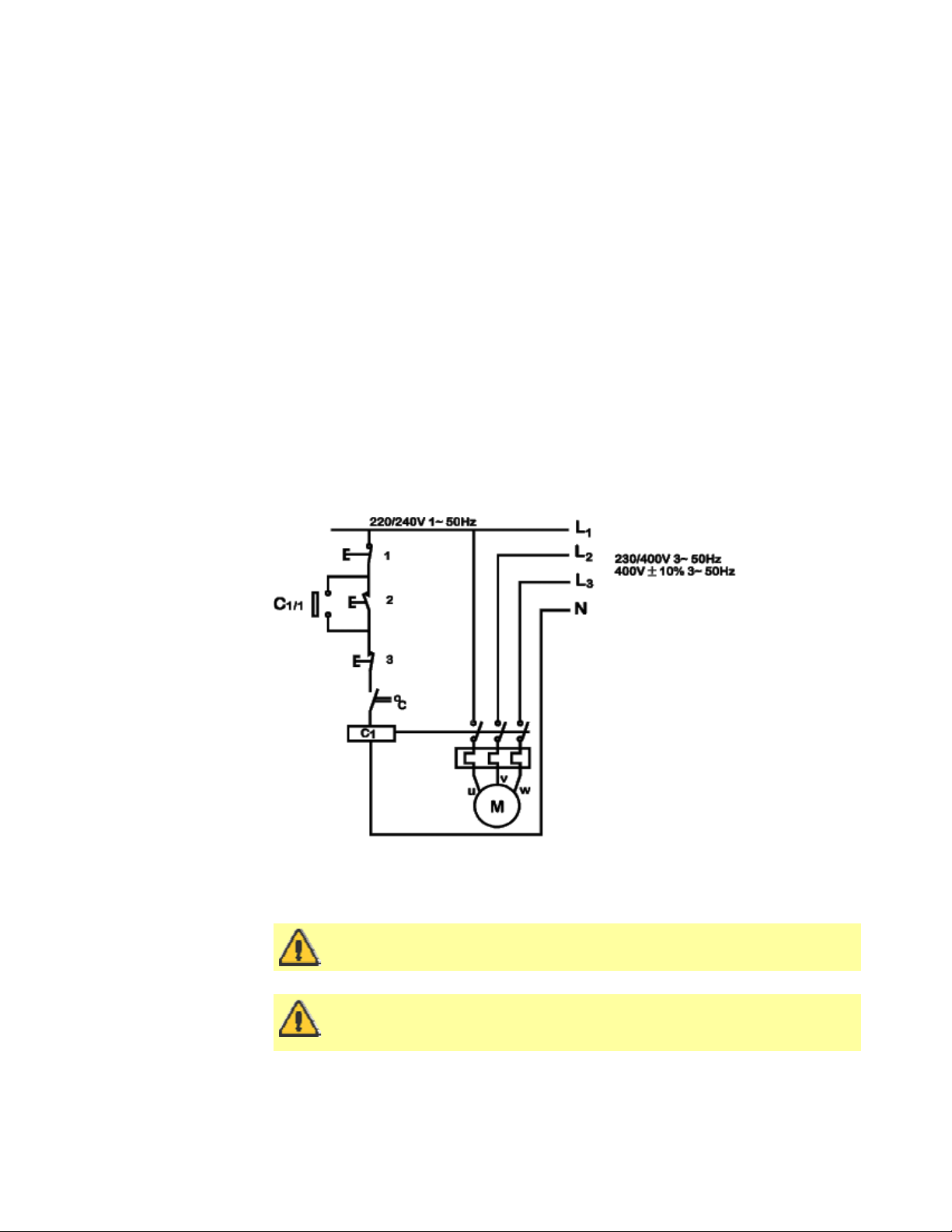
A current overload relay should be fitted to a contact breaker. Connect the motor in
accordance with the wiring diagram that is in the motor terminal box.
When a thermal protection switch is fitted in the motor, the leads will be found in the
motor terminal box. They should be connected to stop the pump if the switch operates.
The switch will open circuit at an over temperature condition. See below for the
connection of the drive motor showing possible ancillary switches and protections.
1. Emergency
stop
2. Start
3. Stop
The ancillary switches are rated to 220/240V 1ph 50Hz. The Start contact should
have a sprung return which will disengage following energisation of the coils C1
and C1/1.
Ensure that an emergency stop switch is fitted within reach of the pump.
The 701R pumphead range has electrostatic earth straps which are
connected to the baseplate. Please ensure that the baseplate is
electrostatically earthed to ground before operation.
14/12/2009file://M:\staging\pdfs-global\m-701baseplate-gb-02.htm
Page 9

Page 9 of 25Watson-Marlow Bredel E-Manuals
Do not under any circumstances wire switches directly across any of the
phases of a 3-phase supply. If in doubt disconnect the pump
immediately!
Do not connect ancillary switches to the terminal box of a flameproof
motor unless the switch has a suitable Ex rating for the zone area in
which it is to be mounted.
8 Troubleshooting
Should the pump fail to operate, make the following checks to determine whether or not
servicing is required.
Check the mains supply is available at the pump.
Check that the pump is not stalled by incorrect fitting of tubing.
Always check to ensure that an EEx-d motor gearbox is suitably rated for
the hazardous zone area in which it is to be mounted. EEx-d motors
should only be installed by EEx-d qualified personnel.
Any deviation from normal operating conditions (increased
power consumption, temperature, vibrations, noise) or
warning signals by monitoring equipment suggest
malfunction. Inform the responsible maintenance personnel
at once to prevent the trouble from worsening. If in doubt
disconnect the pump immediately.
9 AC Motor maintenance
Remove any dust deposits from the fan cover to avoid overheating.
Ensure that the bearing cage is packed to about 1/3 with evenly distributed lubricating
grease.
Suitable lubricant: Mobilux 2 (-30°C-60°C) or similar.
10 Gearbox maintenance
Change lubricant every 10,000 working hours or after 2 years.
Combine a lubricant change with a thorough cleaning of the gear unit.
Extreme working conditions (high air humidity, aggressive media and large temperature
variations) will reduce the interval between lubricant changing intervals.
Suitable lubricant: Mobil XMP 220 (mineral -5°C-40°C) or similar.
Belt variator maintenance
Pulleys are supplied with permanent grease packing. No refill is necessary. The variator
should occasionally be run over its full range to apply a grease coating to the full track.
The control spindle should be cleaned and greased occasionally.
14/12/2009file://M:\staging\pdfs-global\m-701baseplate-gb-02.htm
Page 10

Page 10 of 25Watson-Marlow Bredel E-Manuals
Replacing the V-belt
Unscrew the socket head screws and remove the cover with the entire speed control
mechanism.
Remove the V-belt.
Wrap the new V-belt around the open adjustable pulley and let it slip over the spring
loaded pulley. The V-belt can be easily attached if the adjustable pulley is opened.
Ensure that the adjustable pulley is opened carefully.
Replace the removed cover with the complete speed control mechanism and re-
assemble.
When positioning the top (adjustable pulley closed) speed limiting lock nut, ensure that
the adjustable pulley has a gap of 0.5-1.0mm to prevent damage to the pulley and motor
bearings.
The V-belt should not be in contact with the bottom of the adjustable pulley.
11 701PB Air motors
The air motor is designed for air only. Do not allow corrosive, flammable
or explosive gases or particulate material to enter the motor. Water
vapour, oil-based contaminants, or other liquids must be filtered out. The
recommended air pressure should not exceed 7 bar (100 PSIG)
maximum. Always disconnect the air supply before servicing.
Ensure that the air motor is correctly installed and lubricated in
accordance with the guidelines in this operating instruction. Each air
motor is fitted with an outlet port restrictor to stop the motor running
faster than the maximum designated speed. Failure to observe correct
installation and lubrication procedures with air motors will cause damage
that will invalidate your warranty.
Installation
A silencer is installed on the air motor’s exhaust port. Install a moisture trap and filter in
the air line ahead of the motor. If condensates need to be flushed out of the motor, use
clean, dry air at low pressure. For efficiency of output and speed control, use air lines of the
same size or next pipe size larger than the intake port of the motor. A 4-way valve which
can be connected by piping to both air ports of the motor will make reversing possible. Use
a pressure regulator or a simple shut off valve to obtain desired power and conserve air to
regulate speed and torque.
14/12/2009file://M:\staging\pdfs-global\m-701baseplate-gb-02.htm
Page 11

Page 11 of 25Watson-Marlow Bredel E-Manuals
Lubrication
Use a detergent SAE#10 automotive engine oil. Lubrication is necessary for all moving
parts and rust prevention. We recommend that an automatic air lubricator be installed in
the air line just ahead of the motor.
Automatic lubrication (recommended) - An In-line oiler should be adjusted to feed one
drop per minute for high speed or continuous duty use. Do not overfeed oil as
contamination of the exhaust air may occur.
Manual lubrication - Add 10-20 drops of oil every eight hours of operation through the
inlet port while the pump is shut down.
12 701PB Air motors: troubleshooting
Reason
Dirt, foreign material
Internal rust
Misalignment
Insufficient air pressure
Air line too small
Restricted exhaust
Poor lubrication
Jammed machine
Compressor too small
Compressor too far from
unit
Low
torque
Low
speed
Won't
run
Runs
hot
Runs well
then
slows
14/12/2009file://M:\staging\pdfs-global\m-701baseplate-gb-02.htm
Page 12

Page 12 of 25Watson-Marlow Bredel E-Manuals
13 Pump specification
Control range See pump specification label
Voltage/frequency See pump specification label
Power consumption See pump specification label
Operating temperature range 5°C to 40°C
Storage temperature range -40°C to 70°C
Noise <85dBA at 1m
Standards EN60529 (IP55)
Machinery Directive: 2006/42/EC
EMC Directive: 2004/108/EC
14 701RB Pumphead: key safety information
Before opening the pumphead guard please ensure that these
safety directions are followed.
Ensure that the pump is isolated from mains voltage.
Ensure that there is no pressure in the pipeline.
If a tube failure has occurred, ensure that any product in the pumphead has been
allowed to drain from the pumphead to a suitable drain.
Ensure that protective clothing and eye protection is worn if hazardous products are
being pumped.
15 701R Safe-guarding
Primary safety on 701R electrical and air powered baseplate pumps is provided by the toollockable pumphead guard.
Guard switch
The pumphead has been fitted with two guard switches. When the track is removed, the
pump stops. The pump can be restarted only if the track is returned to its correct position.
14/12/2009file://M:\staging\pdfs-global\m-701baseplate-gb-02.htm
Page 13

Page 13 of 25Watson-Marlow Bredel E-Manuals
16 701RB, 701RBX, 701RBG, 701RBE, 701RBEX
Pump installation
A correctly engineered installation will promote the best possible tube life, so please ensure
that the following guidelines are followed:
On variable speed models please note that the mechanical speed variator must not be
adjusted when the motor is not running.
Do site the fluid reservoir above the pump wherever possible.
Do keep delivery and suction lines as short and direct as possible.
Do use gradual sweeping bends in installation pipe work with minimum radius equal to five
times the tubing diameter. Avoid tight pipeline bends, pipe reducers and excessive lengths
of smaller bore tubing than that in the pumphead, particularly in pipelines on the suction
side.
Do ensure that there is always a minimum of one metre of smooth bore flexible tubing
connected to the discharge port of the pumphead. This will help minimise any impulse
losses and pulsation in the pipeline. This is especially important with viscous fluids and rigid
pipework.
Do use suction and delivery pipelines with a bore equal to or larger than the bore of the
tube fitted in the pumphead. When pumping viscous fluids, the losses caused by increased
friction can be overcome by using pipe runs with a cross sectional area several times
greater than the pumping element.
Do fit an over-length pump tube in the system to allow its position to be varied relative to
the rotor. This will extend tube life and minimise the downtime of the pumping circuit.
Do ensure that connecting pipe work and fittings are suitably rated to handle the predicted
pipeline pressure.
If rigid pipe work comes in close proximity to the pumphead, a drop out section of pipe
work will simplify tube replacement.
Do keep the pumphead rollers and track clean.
If unsure of an installation please contact your local Watson-Marlow Technical Support
Office for further assistance.
All performance figures in this operating instruction relate to peak pipeline pressures. Peak
pressure is not always accurately shown by oil-filled analogue pressure gauges as damping
of the gauge needle occurs. The pressure being recorded using an analogue gauge may
only be 75% of true peak pressure. For accurate peak pressure measurement a digital
pressure transducer should be used.
14/12/2009file://M:\staging\pdfs-global\m-701baseplate-gb-02.htm
Page 14

g
Page 14 of 25Watson-Marlow Bredel E-Manuals
17 Tube loadin
701 baseplate pumps can be operated with a 701RB continuous tubing pumphead or with a
701RBE pumphead fitted with Watson-Marlow LoadSure tube elements. For both pumphead
types, extension "X" pumphead options are available.
701R, 701RB and 701RBX continuous tube loading
Loosen the track compression spring knobs using a 10mm A/F spanner, turning them
anticlockwise six (6) times.
Unscrew the track securing bolt and withdraw the bolt fully. Lift the track by its handle
and slide it out from under the springs.
Release the tube clamps by pulling on the release levers and lift out both clamps.
Lay the tubing across the pumphead. Secure the suction side by sliding in the first tube
clamp while pulling the release lever.
14/12/2009file://M:\staging\pdfs-global\m-701baseplate-gb-02.htm
Page 15

Page 15 of 25Watson-Marlow Bredel E-Manuals
Fit the delivery clamp loosely to allow any excess tubing to work its way through the
pumphead. (See Re-tensioning the tubing, below)
Position the track over the pumphead cradle and locate the track securing bolt. Tighten
the track-securing bolt using the 6mm Allen key provided.
Tighten both the track compression spring knobs to a torque of 3Nm (2.2 lb-ft) using a
10mm A/F spanner.
701RB, 701RBX and 701RBG: Re-tensioning the tubing
Start the pump, allowing any excess tubing to work through the pumphead, then press
down the delivery end clamp firmly. Check the tube for movement when the pump is
running. If tubing moves through the pumphead, the tube should be more firmly clamped
at the suction end. The delivery end should be unclamped to release any excess tubing,
pulled tight and then firmly re-clamped again.
When using Marprene continuous tubing, after the first 30 minutes of running, re-tension
the tube in the pumphead by releasing the tube clamp on the delivery side a little and
pulling the tube tight. This is to counteract the normal stretching that occurs with Marprene
which can go unnoticed and result in poor tube life.
14/12/2009file://M:\staging\pdfs-global\m-701baseplate-gb-02.htm
Page 16

Page 16 of 25Watson-Marlow Bredel E-Manuals
701RBE and 701RBEX LoadSure tube element loading
700 series LoadSure tube elements:
remove the chance of premature tube failure caused by incorrect tube loading;
avoid over-clamping of tubing;
remove the need to re-t ension the tubing;
extend tube life;
reduce maintenance time for tube changeover and cleaning;
offer standard industrial tube connections.
Please note: the pictures below show LoadSure tube element loading into a 701RBE
pumphead fitted to a 701 baseplate pump.
Loosen the track-compression spring knobs using a 10mm A/F spanner, turning them
anticlockwise six (6) times.
Unscrew the track-securing bolt and withdraw the bolt fully. Lift the track by its handle
and slide it out from under the springs.
Locate the D-shaped flange fitt ed to the end of the tube element into the delivery (rig h t-
hand) sliding tube clamp. (The D flange ensures that the element can only be loaded
correctly.)
Slip the right-hand end of the track under the springs.
Locate the second “D”-shaped flange into the suction (left-hand) sliding tube clamp.
(Lifting the sliding tube clamp will aid the tube-loading.)
14/12/2009file://M:\staging\pdfs-global\m-701baseplate-gb-02.htm
Page 17

Page 17 of 25Watson-Marlow Bredel E-Manuals
Position the left-hand end of the t rac k so t hat the track-securing bolt can be inserted.
Tighten the track-securing bolt with the 6mm Allen key provided.
Tighten both the track-compression spring knobs to a torque of 3Nm (2.2 lb-ft) using a
10mm A/F spanner.
Connect both ends of the tubing element to the fluid line using 3/4in female cam and
groove connectors.
18 Fitting an extension
pumphead
From the first pumphead remove:
the plug from the tapped hole in the top right
hand corner of the pumphead frontplate (1);
the track securing bolt and the track (2);
the plug from the slot in the centre shaft (3);
the M8 x 16 socket head cap screw from the
bottom left of the first pumphead (4).
Grease the drive shaft dog of the extension pumphead with the grease supplied.
Apply thread locking compound to the M8 x 16 socket head cap screw in the top right
hand corner of the backplate of the extension pumphead.
Align the drive shaft dog of the extension pumphead with the slot in the drive shaft of
the first pumphead.
Fit the extension pumphead to the first pumphead. Ensure the backplate of the extension
pumphead is flat against the frontplate of the first pumphead.
Lightly tighten the socket head cap screw with the modified 6mm Allen key provided.
Apply thread locking compound to the M8 x 170 socket head cap screw in the bottom left
of the extension pumphead frontplate, and tighten it in sequence with the M8 cap scre w
in the backplate.
14/12/2009file://M:\staging\pdfs-global\m-701baseplate-gb-02.htm
Page 18

19 Pumphead spares: continuous tubing
1
2
Models 701RB, 701RBX, 701RBG
1 MRA0027A Pivot pin assembly
Page 18 of 25Watson-Marlow Bredel E-Manuals
MRA0034A Pivot pin assembly
2 MRA0021A Rotor assembly
MRA0036A Rotor assembly ~
701RB, 701RBX:
3
MRA0104A
701RBG:
MRA0295A
3
MRA0103A Knob assembly ~
4
701RB, 701RBX:
SG0005
701RBG: SG0019
5
701RB, 701RBX:
MR0674T
701RBG: MR0977T
6
MR0880C Tube clamp
7
MR0662T Stud ~ Set to 61mm
8
MRA0154A Track assembly
9
MR0882M Eccentric bush
Knob assembly ~
4.8mm wall tubing
3.2mm wall tubing
501RL Spring retaining
~701RX
701RX
Spring
washer
14/12/2009file://M:\staging\pdfs-global\m-701baseplate-gb-02.htm
Page 19

20 Pumphead spares: tubing elements
1
2
2
2
3
5
6
Models 701RBE, 701RBEX
1 MRA0027A
Page 19 of 25Watson-Marlow Bredel E-Manuals
Pivot pin assembly
MRA0034A
MRA0021A
MRA0036A
3
MRA0104A Knob assembly ~ 4.8mm wall
3
MRA0103A Knob assembly ~ 3.2mm wall
4
SG0005 Spring
5
MR0674T Spring retaining washer
6
MR0662T Stud ~ Set to 61mm
7
MR1118T Sliding clamp
8
MRA0154A
9
MR0882M Eccentric bush
21 Pumphead spares: rotor
All models
Pivot pin assembly ~701RX
Rotor assembly
Rotor assembly ~ 701RX
tubing
tubing
Track assembly
1 MR0667T Spacer
FN0420 Screw M5x16 socket
FN0722 Washer
4 MRA0020A Roller assembly
5 MRA0039A Shaft with sun gear
MRA0040A Shaft with sun gear
MR0879C Rotor flange
7 BB0018 Bearing
countersunk
~701R
~701RX
14/12/2009file://M:\staging\pdfs-global\m-701baseplate-gb-02.htm
Page 20

Page 20 of 25Watson-Marlow Bredel E-Manuals
22 Flow rates
Flow rates were obtained using silicone tubing with the pumphead rotating clockwise,
pumping water at 20°C with zero suction and delivery pressures. For critical applications
determine flow rates under operating conditions.
Tube bore Tube number - # rpm Pressure (+) Suction (-)
Flow rates: 701RB Flow rates: 701RBE
mm 9.6 12.7 15.9 19.0 25.4 12.7 15.9 19.0
inch 3/8 1/2 5/8 3/4 1 1/2 5/8 3/4
# 193 88 189 191 92 88 189 191
45
134
232
348
175
265
316
53 98 135 188 250 98 135 188
156 290 402 558 745 290 402 558
271 503 696 967 1290 503 696 967
406 754 1044 1450 1935 754 1044 1450
204 379 525 729 973 379 525 729
309 574 795 1104 1473 574 795 1104
369 685 948 1317 1757 685 948 1317
14/12/2009file://M:\staging\pdfs-global\m-701baseplate-gb-02.htm
Page 21

Page 21 of 25Watson-Marlow Bredel E-Manuals
23 701RB, 701RBX, 701RBG, 701RBE, 701RBEX
product codes
mm inch # Marprene
9.6 3/8 193
12.7 1/2 88
15.9 5/8 189
19.0 3/4 191 902.0190.048 902.0190.PPC 903.0190.048 913.A190.048
25.4 1 92
mm inch # Neoprene
9.6 3/8 193
12.7 1/2 88
15.9 5/8 189
19.0 3/4 191
25.4 1 92
mm inch # STA-PURE
9.6 3/8 193 960.0096.048
12.7 1/2 88
15.9 5/8 189
19.0 3/4 191
25.4 1 92
902.0096.048 903.0096.048 913.A096.048
902.0127.048 902.0127.PPC 903.0127.048 913.A127.048
902.0159.048 902.0159.PPC 903.0159.048 913.A159.048
902.0254.048 903.0254.048 913.A254.048
920.0096.048
920.0127.048 920.0127.PPC
920.0159.048 920.0159.PPC
920.0190.048 920.0190.PPC 930.0190.048 970.A190.048
920.0254.048 930.0254.048
960.0127.048
960.0159.048
960.0190.048
960.0254.048
Marprene
LoadSure
Neoprene
LoadSure
Bioprene
Butyl Fluorel
Platinum
silicone
14/12/2009file://M:\staging\pdfs-global\m-701baseplate-gb-02.htm
Page 22

24 Flow, pressure and suction
Page 22 of 25Watson-Marlow Bredel E-Manuals
25 Maximum peak working pressure ratings
701RB 701RBX 701RBG 701RBE 701RBEX
2bar 2bar 4bar 2bar 2bar
14/12/2009file://M:\staging\pdfs-global\m-701baseplate-gb-02.htm
Page 23

26 Outline dimensions
Page 23 of 25Watson-Marlow Bredel E-Manuals
14/12/2009file://M:\staging\pdfs-global\m-701baseplate-gb-02.htm
Page 24

Page 24 of 25Watson-Marlow Bredel E-Manuals
27 Trademarks and disclaimer
Watson-Marlow, Bioprene, LoadSure and Marprene are trademarks of Watson-Marlow
Limited.
Fluorel is a trademark of 3M.
Sta-Pure is a trademark of W.L.Gore & Associates.
Disclaimer The information contained in this document is believed to be correct but
Watson-Marlow Limited accepts no liability for any errors it contains, and reserves the right
to alter specifications without notice.
28 Warning not to use pumps in patientconnected applications
Warning These products are not designed for use in, and should not be used for patient
connected applications.
14/12/2009file://M:\staging\pdfs-global\m-701baseplate-gb-02.htm
Page 25

Page 25 of 25Watson-Marlow Bredel E-Manuals
29 Decontamination certificate
In compliance with the UK Health and Safety at Work Act and the Control of Substances
Hazardous to Health Regulations, you are required to declare the substances which have
been in contact with product(s) you return to Watson-Marlow or its subsidiaries or
distributors. Failure to do so will cause delays. Please ensure that you fax us this form and
receive an RGA (Returned Goods Authorisation) before you despatch the product(s). A copy
of this form must be attached to the outside of the packaging containing the product(s).
Please complete a separate decontamination certificate for each product.
You are responsible for cleaning and decontaminating the product(s) before return.
Your name
Address
Postcode/zip
Telephone
Product type
To speed the repair, please
describe all known faults
The product has ...
Names of chemicals handled
with product(s)
Precautions to be taken in
handling these chemicals
Company
Country
Fax
Serial number
Been used Not been used
If the product has been used, please complete all the following sections. If the product has
not been used, please just sign this form.
Action to be taken in the
event of human contact
Signature
I understand that the personal data collected will be kept confidentially in accordance with
the UK Data Protection Act 1998.
RGA number
Your position
Date
Please print out, sign and fax to Watson-Marlow Pumps at +44 1326 376009.
14/12/2009file://M:\staging\pdfs-global\m-701baseplate-gb-02.htm
 Loading...